

Page 1
INSTALLATION
& OPERATION
MANUAL
LED Duo Beam
Introduction ................................................................... 2
Unpacking & Pre-Installation ........................................ 2
Installation & Mounting ................................................. 3
Wiring Instructions ........................................................4
Maintenance .................................................................4
Options & Specifcations.............................................5-6
Flash Pattern Selection ................................................6
Warranty .......................................................................8
Read all instructions and warnings before installing and using.
IMPORTANT:
This manual must be delivered to the end user of this equipment.
INSTALLER:
1
TM
Page 2

Introduction
The LED-Duo BeamTM uses state of the art LEDs and optics to provide a superior optical output. The rugged
design and long life capabilities make it virtually maintenance free. When properly congured, the Duo-Beam
will provide 360 degree coverage and will exceed SAE Class 1 and California Title 13 requirements.
The use of this or any warning device does not ensure that all drivers can or will observe or
react to an emergency warning signal. Never take the right-of-way for granted. It is your
responsibility to be sure you can proceed safely before entering an intersection, driving
against trafc, responding at a high rate of speed, or walking on or around trafc lanes.
The effectiveness of this warning device is highly dependent upon correct mounting and
wiring. Read and follow the manufacturer’s instructions before installing or using this
!
WARNINg!
device. The vehicle operator should insure daily that all features of the device operate cor-
rectly. In use, the vehicle operator should insure the projection of the warning signal is not
blocked by vehicle components (i.e.: open trunks or compartment doors), people, vehicles,
or other obstructions.
This equipment is intended for use by authorized personnel only. It is the user’s responsibility to understand and obey all laws regarding emergency warning devices. The user
should check all applicable city, state and federal laws and regulations.
Code 3, Inc., assumes no liability for any loss resulting from the use of this warning device.
Proper installation is vital to the performance of this warning device and the safe operation
of the emergency vehicle. It is important to recognize that the operator of the emergency
vehicle is under psychological and physiological stress caused by the emergency situation.
The warning device should be installed in such a manner as to: A) Not reduce the output
performance of the system, B) Place the controls within convenient reach of the operator
so that he can operate the system without losing eye contact with the roadway.
Emergency warning devices often require high electrical voltages and/or currents. Properly protect and use caution around live electrical connections. Grounding or shorting of
electrical connections can cause high current arcing, which can cause personal injury and/
or severe vehicle damage, including re.
PROPER INSTALLATION COMBINED WITH OPERATOR TRAINING IN THE PROPER
USE OF EMERGENCY WARNING DEVICES IS ESSENTIAL TO INSURE THE SAFETY
OF EMERGENCY PERSONNEL AND THE PUBLIC.
Unpacking & Pre-installation
Carefully remove the light bar and place it on a at surface, taking care not to scratch the lenses or damage
the cable coming out of the bottom. Examine the unit for transit damage, broken lamps, etc. Report any
damage to the carrier and keep the shipping carton.
The LED Duo BeamTM is built to operate on 12 volt D.C. negative ground (earth) vehicles. If you have an
electrical system other than 12 volt D.C. negative ground (earth) contact the factory.
2
Page 3
Installation & Mounting
In all cases, mount the lightbar so that the rubber edging that ts between the lens and the alu-
minum base faces to the front or the side of the vehicle.
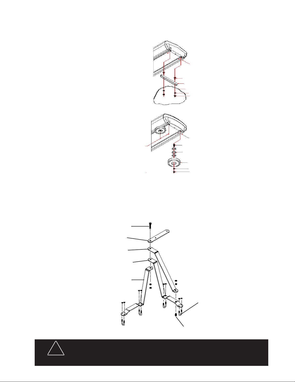
FLUSH MOUNT
Slide bolts through track in
bottom of beacon. Place spacer
over bolts as shown in FIGURE 1.
Align bolts with pre drilled holes in
vehicle's surface. Place lock washer
and nut on bolt then tighten until snug.
NOTE: Spacer must be used to prevent water from entering the bar.
BOTTOM END VIEW OF BEACON
5/16-18 X 1 1/2" CARRIAGE BOLT (PN 240)
MOUNTING SPACER (S50179)
VEHICLE MOUNTING SURFACE
5/16" SPLIT LOCK WASHER (PN 245)
5/16-18 SS HEX NUT (PN 244)
MAGNETIC MOUNT
Slide bolts through track in bottom of ..
beacon approximately 2.25 inches from
end. Place molded shims over bolts as
shown. Attach magnetic base over bolts.
Place lock washer and nut on bolt then
tighten until snug.
MIRROR MOUNT BRACKET
1. Assemble the brackets, tighten the 3/8 bolt but leave the 7/16 bolt nger tight at this time.
2. Position bracket assembly on top mirror supports, bracket A on rear support and bracket B on front sup-
port. Note: some mirror designs require reversing bracket A and B. Rotate bracket A as necessary to get
the best t. Some additional bending of brackets may be necessary in some cases to achieve a satisfactory t.
3. Attach bracket assembly to mirror supports with U-bolts, position bracket assembly as desired and tighten
U-bolts. The Duo Beam mounting bracket should be parallel to the ground.
5/16-18 X 1 1/2" CARRIAGE BOLT (PN 240)
MOLDED SHIM (PN 1064)
RB 80 MAGNETIC BASE (PN 499)
5/16" SPLIT WASHER (PN 245)
5/16-18 SS HEX NUT (PN 244)
!
WARNINg!
7/16 BOLT
DuO BEAM MOuNTINg
BRACKET
BRACE
BRACKET B
BRACKET A
Utilizing non-factory supplied screws and/or mounting brackets and/or the
improper number of screws may result in loss of warranty coverage on the
equipment.
fIguRE 1
u-BOLT
3/8 BOLT
3
Page 4

Lightbar Wiring Instructions
Larger wires and tight connections will provide longer service life for components. For
high current wires it is highly recommended that terminal blocks or soldered connections
be used with shrink tubing to protect the connections. Do not use insulation displace-
!
WARNINg!
ment connectors (e.g. 3M® Scotchlock type connectors). Route wiring using grommets
and sealant when passing through compartment walls. Minimize the number of splices
to reduce voltage drop. High ambient temperatures (e.g. underhood) will signicantly
reduce the current carrying capacity of wires, fuses, and circuit breakers. Use "SXL"
type wire in engine compartment. All wiring should conform to the minimum wire size
and other recommendations of the manufacturer and be protected from moving parts
and hot surfaces. Looms, grommets, cable ties, and similar installation hardware
should be used to anchor and protect all wiring. Fuses or circuit breakers should be
located as close to the power takeoff points as possible and properly sized to protect
the wiring and devices. Particular attention should be paid to the location and method
of making electrical connections and splices to protect these points from corrosion and
loss of conductivity. Ground terminations should only be made to substantial chassis
components, preferably directly to the vehicle battery. The user should install a fuse
sized to approximately 125% of the maximum Amp capacity in the supply line to protect
against short circuits. For example, a 30 Amp fuse should carry a maximum of 24 Amps.
DO NOT USE 1/4" DIAMETER GLASS FUSES AS THEY ARE NOT SUITABLE FOR
CONTINUOUS DUTY IN SIZES ABOVE 15 AMPS. Circuit breakers are very sensitive
to high temperatures and will "false trip" when mounted in hot environments or operated
close to their capacity.
Route the wiring cables into the engine or passenger compartment, taking care to use grommets and to
apply sealant around openings to keep water out. It is advisable to leave an extra loop of cable when
installing the light bar to allow for future changes or reinstallations. Connect the black lead to a solid
frame ground (earth), preferably, the (-) or ground (earth) side of the battery, and the red power wire to
the +12V terminal of the battery through an appropriately rated fuse ( see the fusing considerations sec-
tion for fuse selection ) or breaker. If there is a white wire in the cable, it is not used.
!
This Product contains high intensity LED devices. To prevent eye damage,
DO NOT stare into light beam at close range.
WARNINg!
LED Fusing Considerations
Although the average current draw per LED module is very low, the instantaneous peak current to a module can be higher during low voltage conditions. To avoid prematurely blowing of ATO style fuses or tripping
breakers it is recommended the following rule-of-thumb be used to size fuses or breakers. This is especially important in light bars with many LED modules running off a single fused source.
Minimum fuse size calculation:
1.5 x (number of modules being fused)
Example:
LED Duo Beam TM Light bar with 4 LED modules .
Minimum fuse requirement for single fuse - 1.5 (4) = 6A minimum
Maintenance
Lens Cleaning
Use plain water and a soft cloth, or Code 3 lens polish and a very soft paper towel or facial tissue. Because
plastic scratches easily, cleaning is recommended only when necessary (about every six months). Do not
subject the lenses to car washes that use brushes, as these will scratch the lenses.
4
Page 5

Dim Operation
Lightbar LED modules are equipped with a low power "Dimming" mode. Dimming will be controlled by applying +12V by way of the
appropriate wire(color) in the wire harness/wire list. When DIM is engaged the LED's will operate in a reduced power mode. For
safety purposes, the corner modules in lightbars are not connected to the dimming circuit. This ensures that when corner modules
are turned on, full 360 degree coverage and compliance with SAE warning light standards is provided. The DIM control wires(two
white wires) located on each of the modules are connected from one module to the next. To disable the dimming function on a
particular module, disconnect the white wires. Then reconnect the white wire to the white wire on another module that has dimming
enabled.
The Dim setting reduces the light output of emergency warning lights reducing the effectiveness of
them especially in brightly lit areas. Failure to use adequate light for the circumstances can cause
motorists to fail to see the emergency vehicle and lead to serious personal injury or death. Never
use the DIM setting in a brightly lit area. Use of the DIM setting may cause emergency lights to not
WARNINg!
comply with applicable emergency warning light standards. Use caution when using the DIM setting to
assure that motorists can clearly see the emergency vehicle.
Code 3® PriZm II™ LED Reector 360° Corner Modules
The RX 2700 Lightbar is equipped with new Code 3® PriZm II™ LED Reector 360° corner LED modules that provide a full
360° of warning. The lighthead has been designed to exceed all applicable requirements for 360° warning devices in Red,
Blue, Amber and White.
Operating Specications for 360° module:
Operating Voltage: 10-16 VDC, Reverse Polarity Protection
Current Draw : Red/Amber - .5A avg @ 12.8 Volts
Blue/White - .8A avg @ 12.8 Volts
Available Colors - Red, Blue, Amber and White
Master/Slave Operation (See Directional Modules section below if so equipped)
Some 360 degree corner modules consist of a "master" and a "slave" driver circuit board and LED light engines with a single
integrated heatsink bracket. The "master" circuit board (rear position) must always be powered for the "slave"(front position)
to ash. The "master" is always located in the rear position of the module. The lightbar is wired to allow running only the rear
facing LED on each module by removing power to the front facing "slave" module. This gives a "front-cutoff" function. The
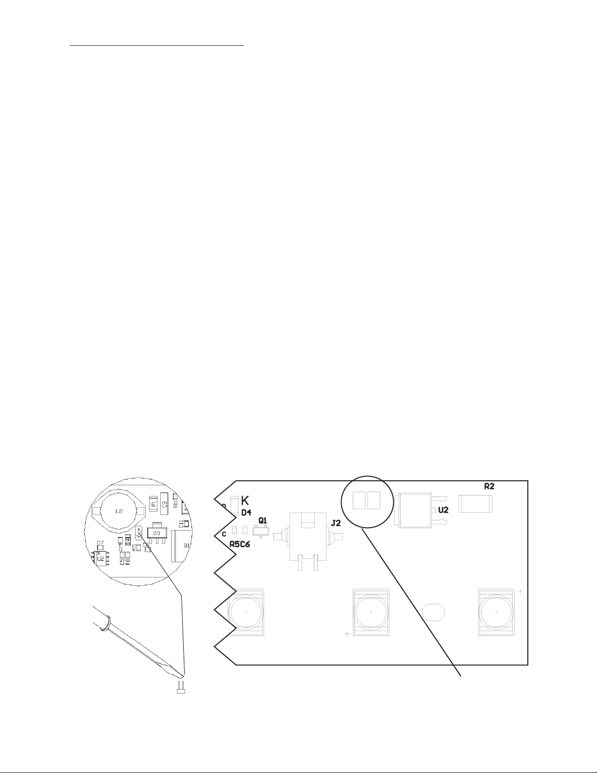
ash pattern for each corner pair can be selected by shorting together the 2-pin header J1, on the "master" momentarily and
releasing. The module is set-up for "Cycle Flash" as a standard. Holding down the 2-pin header for 5 seconds, or longer, and
releasing will return the pattern to Cycle Flash. The following chart describes the available patterns and order (Both heads will
be in the mode selected. Both heads will ash together unless in Front Cut-off mode):
360 Degree Module Flash Pattern - Table 1 (If so equipped)
See Figure 1, for 2-pin header location.
Flash Pattern
Cycle Flash (default)
Quad Flash70
Mode Flash
NFPA Quad Flash75
Five Flash70
Triple Flash70
Quad Pop Flash70
LED DIRECTIONAL MODuLES
In addition to the 360 warning modules the lightbar may be equipped with a number of single head front-rear warning LED mod-
ules. These modules are available in either the, PriZm II LED REFLECTOR Module, 3-LED REFLECTOR, 3-LED OLP OPTIX
(dual stack 3-LED lightheads) in steady-burn and ashing versions. The steady-burn versions can be ashed by connecting the
module(s) to any asher that does not require ground through the load (example: Code 3® 900 series asher). The ashing
modules will have "Cycle Flash" as the standard pattern. The ash pattern can be changed by shorting the 2-pin header, J1 as
shown in Figure 1, momentarily then releasing. Table 1 shows the available patterns and the order when stepping through pat-
terns. The module can be reset to "Cycle Flash" by shorting the header for greater than 5 seconds and releasing.
See next page for operating specications and available colors for front-rear modules.
5
Page 6
LED DIRECTIONAL MODULES (CONT)
Operating Specications for front-rear module:
Operating Voltage: 10-16 VDC, Reverse Polarity Protection
Current Draw: Flashing Module:
Red/Amber - .25A avg @ 12.8 Volts
Blue/White - .40A avg @ 12.8 Volts
Steady Burn Module:
Red/Amber - .5A avg @ 12.8 Volts
Blue/White - .8A avg @ 12.8 Volts
Available Colors: Red , Blue, Amber, and White
Flash Pattern Selection
Directional module Flash Pattern - Table 1
Flash Pattern Description
1. Cycle Flash (DEFAULT)-------------Cycles through various patterns @ 70 fpm
2. NFPA Quad Flash 80 FPM----------Four Pulses per ash @ 80 fpm
3. Steadyburn------------------------------Steady-Burn
4. Five Flash 150 FPM------------------Five Pulses per ash @ 150 fpm
5. Quad Flash 150 FPM-----------------Four Pulses per ash @ 150 fpm
6. Triple Flash 150 FPM ----------------Three Pulses per ash @ 150 fpm
7. Double Flash 150 FPM---------------Two Pulses per ash @ 150 fpm
8. Single Flash 150 FPM----------------One Pulse per ash @ 150 fpm
9. Single Flash 250 FPM----------------One Pulse per ash @ 250 fpm
10. Single Flash 375 FPM---------------One Pulse per ash @ 375 fpm
11. Triple Pop Flash 75 FPM------------Three Pulses per ash ( 2 equal, 1 extended) @ 75 fpm
12. Quad Pop Flash 75 FPM------------Four Pulses per ash ( 3 equal, 1 extended) @ 75 fpm
13. Single Flash 75 FPM------------------One Pulse per ash @ 75 fpm
14. Double Flash 75 FPM-----------------Two Pulses per ash @ 75 fpm
15. Triple Flash 70 FPM ------------------Three Pulses per ash @ 70 fpm
16. Quad Flash 70 FPM ------------------Four Pulses per ash @ 70 fpm
Located on rear of
PCB
17. Five Flash 70 FPM --------------------Five Pulses per ash @ 70 fpm
18. Mod Flash
19. Action Flash
PCB (Color - Green)
J1
fOR APPLICATIONS uSINg
SEPARATE PCB & LIgHT
ENgINES
Located on front of
Integrated PCB/
Light Engine
PCB
Reector removed
for clarity
PCB (Color - Black)
fOR APPLICATIONS uSINg
INTEgRATED PCB/LIgHT ENgINE
(ONE-PIECE)
6
Momentarily short
and release to
change patterns
Page 7

Notes
7
Page 8

WARRANTY
Code 3, ®Inc.'s emergency devices are tested and found to be operational at the time
of manufacture. Provided they are installed and operated in accordance with manufacturer's
recommendations, Code 3, Inc. guarantees all parts and components except the lamps to a period
of 1 year, LED Lighthead modules to a period of 5 years (unless otherwise expressed) from the
date of purchase or delivery, whichever is later. Units demonstrated to be defective within the
warranty period will be repaired or replaced at the factory service center at no cost.
Use of lamp or other electrical load of a wattage higher than installed or recommended by
the factory, or use of inappropriate or inadequate wiring or circuit protection causes this warranty
to become void. Failure or destruction of the product resulting from abuse or unusual use and/
or accidents is not covered by this warranty. Code 3, Inc. shall in no way be liable for other
damages including consequential, indirect or special damages whether loss is due to negligence
or breach of warranty.
CODE 3, INC. MAKES NO OTHER ExPRESS OR IMPLIED WARRANTY INCLUDING, WITHOUT LIMITATION, WARRANTIES OF FITNESS OR MERCHANTABILITY, WITH
RESPECT TO THIS PRODUCT.
PRODUCT RETURNS
If a product must be returned for repair or replacement*, please contact our factory to
obtain a Return Goods Authorization Number (RGA number) before you ship the product to
Code 3, Inc. Write the RGA number clearly on the package near the mailing label. Be sure
you use sufcient packing materials to avoid damage to the product being returned while in
transit.
*Code 3, Inc. reserves the right to repair or replace at its discretion. Code 3, Inc. assumes no responsibility or liability for expenses incurred
for the removal and /or reinstallation of products requiring service and/or repair.; nor for the packaging, handling, and shipping: nor for the handling of
products return to sender after the service has been rendered.
PROBLEMS OR QUESTIONS? CALL OUR TECHNICAL ASSISTANCE HOTLINE (314) 996-2800
WWW.CODE3PSE.COM
Code 3® is a registered trademark of Code 3, Inc., a subsidiary of Public Safety Equipment, Inc.
8
Code 3®, Inc.
St. Louis, Missouri 63114-2029—USA
Ph. (314) 426-2700 Fax (314) 426-1337
10986 N. Warson Road
Part No. T07594 Rev. 2 8/2009
©2009 Code 3, Inc
 Loading...