

Page 1
INSTALLATION &
OPERATION
MANUAL
HIDE-A-WAY
STROBE LIGHT HEADS
HIDE-A-WAY STROBE LIGHT HEADS
Contents:
Introduction ......................................................... 2
Unpacking & Pre-Installation .............................. 2
Installation ........................................................ 3-4
Parts & Exploded View ....................................... 5
Maintenance ....................................................... 6
Options ............................................................... 6
Notes .................................................................. 7
Warranty ............................................................. 8
IMPORTANT:
Read all instructions and warnings before installing and using.
INSTALLER: This manual must be delivered to the end user of this equipment.
Page 2

Introduction
The Hide-A-Way Strobe Light Heads are designed as auxiliary lights for the emergency vehicle market. The
light heads can be used with either the
by using the optional cable assemblies. Use of any other power supply may cause shortened service life of
the strobe tube.
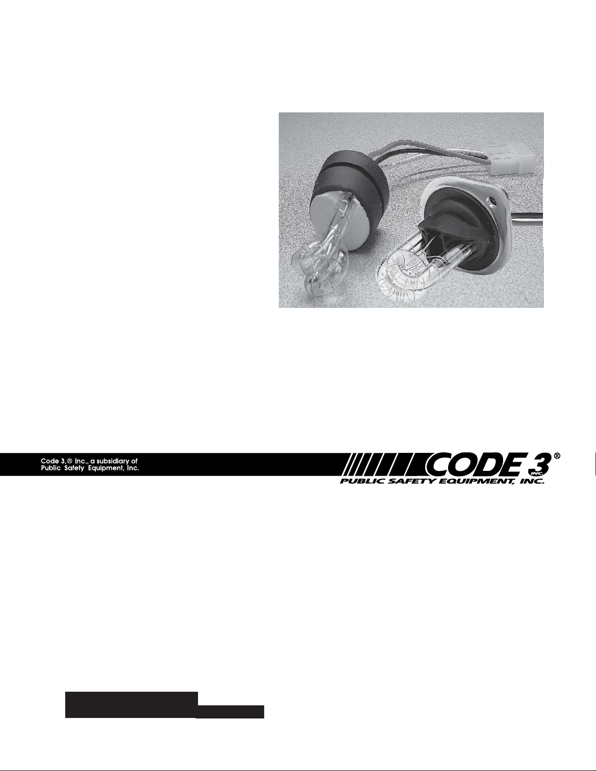
Consisting only of a clear or colored strobe tube assembly, flange bracket, mounting fasteners and a gasket,
the Hide-A-Way Strobe is easy to install. The design allows the user to customize the lighting system without
changing the vehicles appearance. For installations or replacements after 1/1/2005, the new grommet stlye
tube is supplied. This eliminates the need of the flange and gasket.
The use of this or any warning device does not insure that all drivers can or will observe or
react to an emergency warning signal. Never take the right-of-way for granted. It is your
responsibility to be sure you can proceed safely before entering an intersection, driving
against traffic, responding at a high rate of speed, or walking on or around traffic lanes.
The effectiveness of this warning device is highly dependent upon correct mounting and
!
WARNING!
wiring. Read and follow the manufacturer’s instructions before installing or using this
device. The vehicle operator should insure daily that all features of the device operate
correctly. In use, the vehicle operator should insure the projection of the warning signal is
not blocked by vehicle components (i.e.: open trunks or compartment doors), people,
vehicles, or other obstructions.
This equipment is intended for use by authorized personnel only. It is the user’s responsibility to understand and obey all laws regarding emergency warning devices. The user
should check all applicable city, state and federal laws and regulations.
Public Safety Equipment, Inc., assumes no liability for any loss resulting from the use of
this warning device.
Proper installation is vital to the performance of this warning device and the safe operation
of the emergency vehicle. It is important to recognize that the operator of the emergency
vehicle is under psychological and physiological stress caused by the emergency situation.
The warning device should be installed in such a manner as to: A) Not reduce the output
performance of the system, B) Place the controls within convenient reach of the operator
so that he can operate the system without losing eye contact with the roadway.
Emergency warning devices often require high electrical voltages and/or currents. Properly
protect and use caution around live electrical connections. Grounding or shorting of
electrical connections can cause high current arcing, which can cause personal injury and/
or severe vehicle damage, including fire. Do not touch the strobe light tubes, the strobe
light head assemblies or the strobe power supply while the system is in operation. Wait 10
minutes after turning off the power from system before touching any internal components.
PROPER INSTALLATION COMBINED WITH OPERATOR TRAINING IN THE PROPER
USE OF EMERGENCY WARNING DEVICES IS ESSENTIAL TO INSURE THE SAFETY
OF EMERGENCY PERSONNEL AND THE PUBLIC.
CODE 3
®
or
PSE Amber
TM
, 2 head or 4 head Strobe Power Supplies
The inherent variability of where the user mounts the strobe lamp unit in the reflector
!
WARNING!
assembly and the resultant non-optimal use of the reflector optics preclude certification to
the requirements of Ca. Title XIII, SAE, AAMVA, GSA, KKK, 1822C or may invalidate DOT/
SAE certification of OEM lighting. The units are intended for SECONDARY warning only
and are intended for USE IN CONJUNCTION with an approved PRIMARY warning light
system.
Unpacking And Pre-Installation
Carefully remove the light head from its protective packaging. Inspect the unit for transit damage (broken
strobe tube, etc). Report any damage to the carrier and keep the shipping carton. Verify that two #6 x 1/2”
screws per lighthead are included (flange mount tubes only). The optional three wire cable comes in a 15, 20
or 25 foot length. Both ends of the cable have Amp #60619-0 sockets attached to each wire. The cable comes
with a parts bag consisting of 2 AMP #1-480303-0 Mate-N-Lok socket housings and 1 #8 noninsulated ring
terminal. Verify that these items are also included.
2
Page 3
Installation
1. Select the desired mounting for the Hide-A-Way strobe light assembly, keeping in mind that the strobe light
will share the same reflector as the headlight, brake light or turn signal lighting. Make sure that the Hide-AWay Strobe Light does not interfere with the proper operation of these lights see Figure 2.
2. Remove the reflector assembly from the vehicle. Choose a surface in the rear or bottom of the housing
which is as flat as possible and as close to the reflector focal point as possible see Figure 2. Using a one
inch diameter hole saw, cut a clearance hole for the Hide-Away strobe light in the housing as shown in Figure
3 (figure 3 may be used as a template). If installing the flange style tube, mark the location of the holes for
the two mounting screws, then with a .078 inch bit, drill both holes. Remove the backing from the flange
gasket to expose the adhesive. Carefully stick the gasket to the reflector assembly ensuring that it is properly
aligned with the three predrilled holes. Place the strobe light head flange onto the strobe tube assembly,
Twist clockwise until it stops.
3. Install the strobe tube assembly into the reflector as shown in Figure 5. Weather seal around the grommet
with a bead of silicone.
4. With the cable end located at the light head mounting location, route the three wire cable to the strobe
power supply. Allow three inches minimum slack at the light head to facilitate strobe tube assembly replacement. Route the cable to the strobe power supply securing the cable along the way as necessary.
5. At the light head and power supply ends of the cable, insert the 3 AMP sockets into the AMP socket
housing as shown in Figure 4.
AT THE LIGHT HEAD END ONLY
, Cut the shield wire flush with the jacket.
6. At the power supply end of the cable, determine if the cable length is acceptable. If a shorter length is
required, bundle the excess cable and secure it with a wire-tie. Crimp the #8 ring terminal to the shield wire
and attach to the nearest chassis grounded structure.
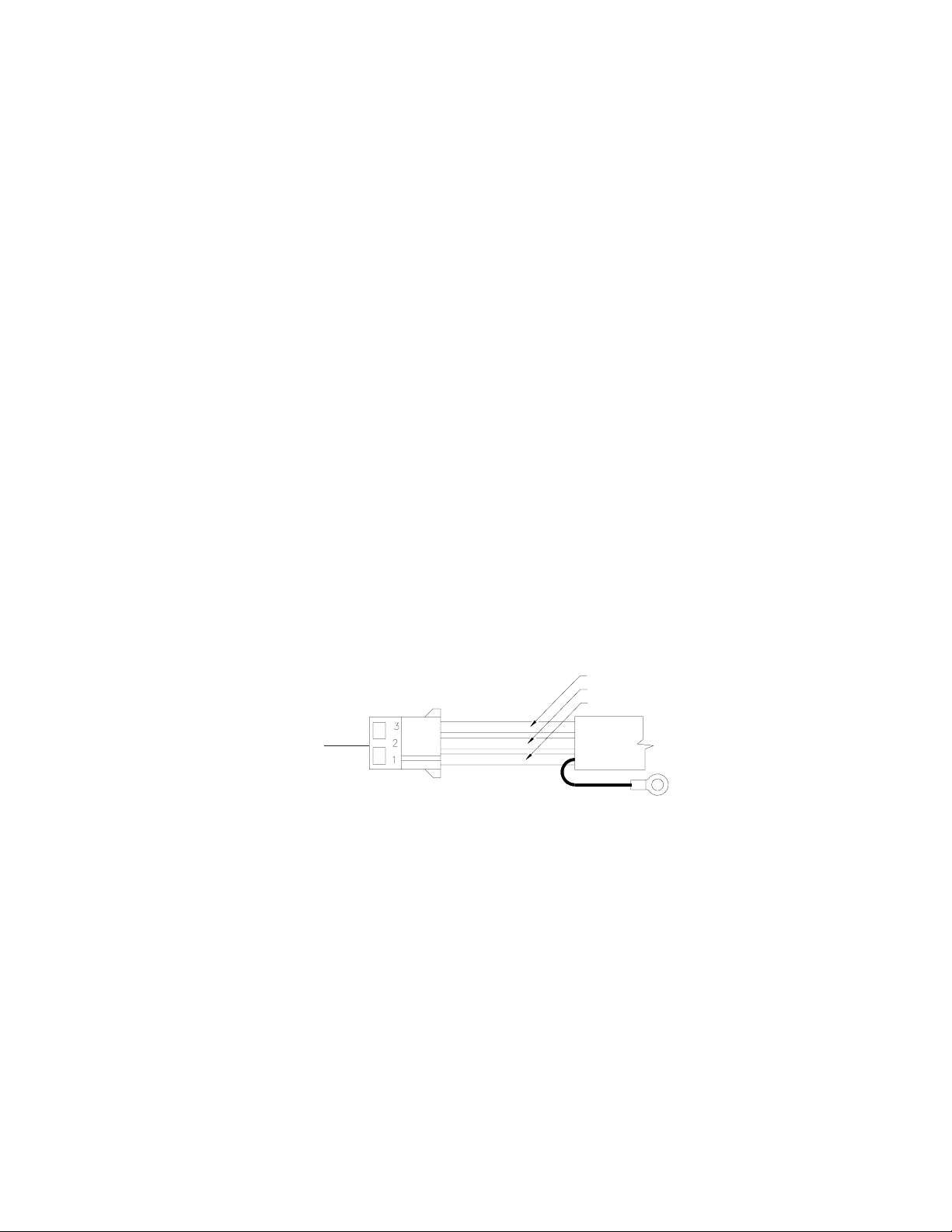
WHITE WIRE - TRIGGER
BLACK WIRE - CATHODE
RED WIRE - HIGH VOLTAGE
THIS END TO POWER
SUPPLY
FIGURE 1
SHIELD WIRE
9. Test the strobe tube by connecting the cable to the Strobe Power Supply per the instructions with the power
supply.
3
Page 4
!
WARNING!
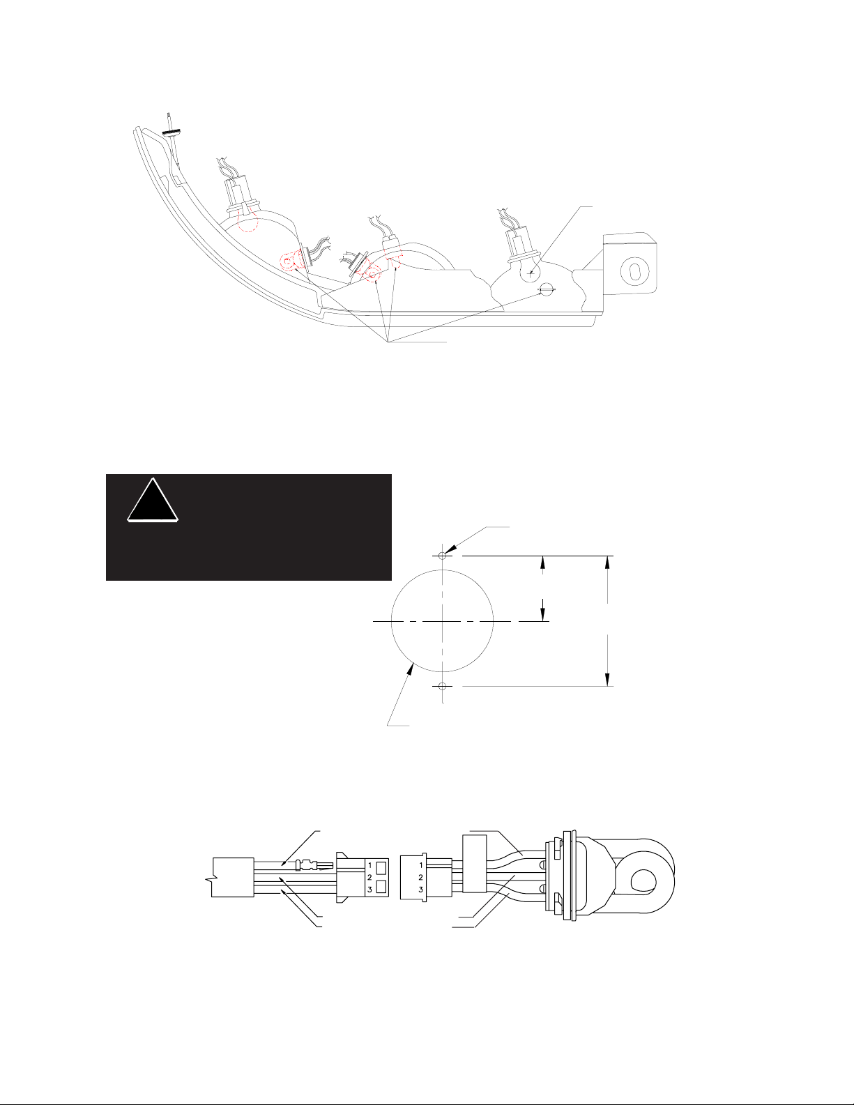
ILLUSTRATION OF AN AUTOMOTIVE
"COMPOSITE" HEADLIGHT OR
TAILLIGHT HOUSING ASSEMBLY
This is a full size template.
Do not use a facsimile or
copied reproduction. Do not
use this template if the largest
dimension in each direction is
not within +/-.040.
FOCAL POINT OF REFLECTOR
IS TYPICALLY THE FILAMENT
LOCATION OF THE LAMP
INSERT STROBE LAMP UNIT FROM THE BACK OR
BOTTOM OF THE HEADLIGHT OR REAR STOPLIGHT HOUSING, AS CLOSE AS POSSIBLE TO THE
FOCAL POINT WITHOUT BLOCKING LIGHT
OUTPUT FROM THE EXISTING LAMPS
FIGURE 2
2X .078 DIAMETER HOLES FOR MOUNTING SCREWS (flange mount only!)
.641
1.282
1.000 DIAMETER MOUNTING HOLE
FIGURE 3
RED WIRE - HIGH VOLTAGE
BLACK WIRE - CATHODE
WHITE WIRE - TRIGGER
*NOTE: VERIFY STROBE TUBE HARNESS HAS WIRE ARRANGEMENT INDICATED
FIGURE 4
4
Page 5

Parts & Exploded
Views
After installing, weather seal
around the grommet.
1A
VEHICLE'S
REFLECTOR
FIGURE 5
Parts List
Description Part No.
Strobe Tube Assembly HSTCL (Clear)
(Orders before 1/1/2005 only)
Flange Gasket T07705
Strobe Tube Flange S70195
#6 Sheet Metal Screw, .50 long T02797
NOTE:
uses the flange style mount, remove the mounting screws and flange with the old tube. The grommet style
tube will mount in the existing 1" hole. Seal around the tube and the old screw holes with silicone based
sealer.
All replacement tubes ordered after 1/1/2005 will be of the new grommet style. If your installation
HSTCR (Red)
HSCTB (Blue)
HSTCA (Amber)
5
Page 6

Maintenance
Strobe Tube Assembly Replacement
High voltages and /or temperatures are present inside the unit. Disconnect from power and wait 10
!
WARNING!
1.Turn off power to the strobe power supply and allow the strobe tube assembly to cool for 10 minutes.
2. Disconnect the strobe tube assembly from the cable.
3. If necessary, remove the reflector assembly that houses the faulty tube.
4. Remove the strobe tube assembly from the reflector assembly, being careful not to strip threads in the reflector, and ensuring that all of the gasket material is removed as well.
5. Insert the strobe tube assembly into the reflector, see steps 3 & 4, page 3. Reinstall the reflector assembly.
6. Test the strobe tube by connecting the strobe tube assembly to the cable. Switch the power supply on. After
verifying the tube is good, turn off the power supply.
minutes prior to servicing or troubleshooting. Use hand and eye protection when changing halogen
lamps or flashtubes as they are pressurized and accidental breakage can result in flying glass.
Options
The Hide-A-Way Strobe product group includes the following models:
Single Products
HSTCL Clear strobe tube assembly and this manual
HSTCX
HIDCL Contains one HSTCL and a 15 foot cable.
HIDCX Contains one HSTCX and a 15 foot cable.
2
1
- Optional 20 or 25 foot cable is also available.
2
- Specify desired strobe tube color (R,B,A,G) when ordering replacement colored strobe tube assem-
blies.
Red, Blue, Amber or Green strobe tube assembly and this manual
1
6
Page 7

NOTES:
7
Page 8

WARRANTY
This product was tested and found to be operational at the time of manufacture.
Provided this product is installed and operated in accordance with the manufacturer's
recommendations, Code 3, Inc. guarantees all strobe head assemblies and all other parts
and components for a period of 1 year from the date of purchase or delivery, whichever is
later. Units demonstrated to be defective within the warranty period will be repaired or
replaced at the factory service center at no cost.
Use of a lamp or other electrical load of a wattage higher than installed or recommended by the factory, or use of inappropriate or inadequate wiring or circuit protection
causes this warranty to become void. Failure or destruction of the product resulting from
abuse or unusual use and/or accidents is not covered by this warranty. Use of non-Code 3
components and assemblies may cause damage to the system and/or personal injury, and
voids all warranties on Code 3, Inc. systems and components.
Code 3, Inc. shall in no way be liable for other damages including consequential,
indirect or special damages whether loss is due to negligence or breach of warranty.
CODE 3, INC. MAKES NO OTHER EXPRESS OR IMPLIED WARRANTY INCLUDING, WITHOUT LIMITATION, WARRANTIES OF FITNESS OR MERCHANTABILITY,
WITH RESPECT TO THIS PRODUCT.
®
PRODUCT RETURNS
In order to provide you with faster service, if you are going to return a product for
repair or replacement*, please contact our factory to obtain a Return Goods Authorization
Number (RGA number) before you ship the product to Code 3. Write the RGA number
clearly on the package near the mailing label. Be sure you use sufficient packing materials
to avoid damage to the product being returned while in transit.
*Code 3, Inc. reserves the right to repair or replace product at its discretion and assumes no responsibility
or liability for expenses incurred for the removal and/or reinstallation of products requiring service and/or repair.
Problems or Questions? Call our Technical Assistance HOTLINE - (314) 996-2800
St. Louis, Missouri 63114-2029—USA
10986 N. Warson Road
www.code3pse.com
Code 3, Inc.
Code 3 is a trademark Code 3, Inc. a subsidiary of Public Safety Equipment, Inc.
Revision 6, 12/2005 - Instruction Book Part No. T07715
©2005 Code 3, Inc. Printed in USA
 Loading...