

Page 1
料號
ZCAR-F07-CO3
:
:雙面彩色印刷
材質
, 120P
道林紙
:
尺寸
編號:
A3(420x297mm)
GD102XXXXXX
日期
摺法:對折加
20130731(
:
WARRANTY
Code 3®, Inc.’s emergency devices are tested and found to be operational at the time of manufacture. Provided
they are installed and operated in accordance with manufacturer’s recommendations, Code 3®, Inc. guarantees all parts
and components except the lamps to a period of 1 year, LED Light head modules to a period of 5 years (unless otherwise
expressed) from the date of purchase or delivery, whichever is later. Units demonstrated to be defective within the warranty
period will be repaired or replaced at the factory service center at no cost.
Use of lamp or other electrical load of a wattage higher than installed or recommended by the factory, or use of
inappropriate or inadequate wiring or circuit protection causes this warranty to become void. Failure or destruction of the
product resulting from abuse or unusual use and/or accidents is not covered by this warranty. Code 3®, Inc. shall in no way
be liable for other damages including consequential, indirect or special damages whether loss is due to negligence or breach
of warranty.
1.0)
版本
十字摺三摺
INSTALLATION &
OPERATION MANUAL
12/24VDC
CODE 3®, INC. MAKES NO OTHER EXPRESS OR IMPLIED WARRANTY INCLUDING, WITHOUT LIMITATION,
WARRANTIES OF FITNESS OR MERCHANTABILITY, WITH RESPECT TO THIS PRODUCT.
PRODUCT RETURNS
If a product must be returned for repair or replacement*, please contact our factory to obtain a Return
Goods Authorization Number (RGA number) before you ship the product to Code 3®, Inc. Write the RGA
number clearly on the package near the mailing label. Be sure you use sufficient packing materials to
avoid damage to the product being returned while in transit.
*Code 3®, Inc. reserves the right to repair or replace at its discretion. Code 3®, Inc. assumes no responsibility or liability for expenses incurred for the removal and /or reinstallation of products requiring service
and/or repair.; nor for the packaging, handling, and shipping: nor for the handling of products returned to sender after the service has been rendered.
Problems or Questions? Call The Technical Assistance HOTLINE - (314) 996-2800
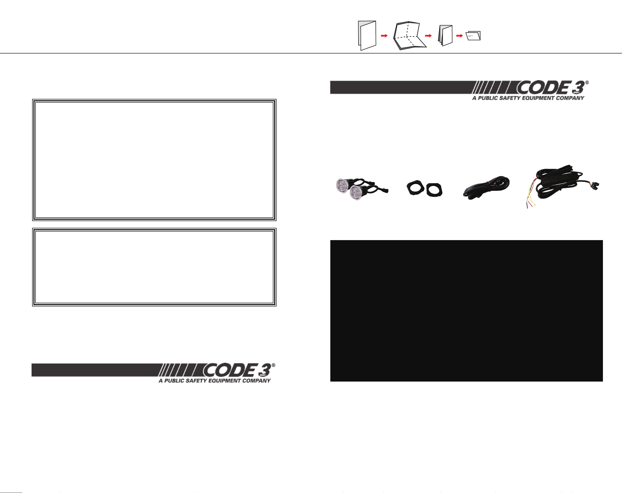
LIGHTHEAD x 2pcs
MOUNTING
GROMMET x 2pcs
EXTENSION CABLE
LED CONTROLLER
4 Pack LED H-A-B (Hide-A-Blast) Exterior
WARNING: This product contains high intensity LED devices. To prevent eye damage, DO NOT stare into the light
beam at close range.
WARNING: The use of this or any warning device does not ensure that all drivers can or will observe or react to an
emergency warning signal. Never take the right-of-way for granted. It is your responsibility to be sure you can proceed safely before entering an intersection, driving against traffic, responding at a high rate of speed, or walking on or
Read and follow the manufacturer’s instructions before installing or using this device. The vehicle operator should
insure daily that all features of the device operate correctly. In use, the vehicle operator should insure the projection of
the warning signal is not blocked by vehicle components (i.e.: open trunks or compartment doors), people, vehicles, or
other obstructions. This equipment is intended for use by authorized personnel only. It is the user’s responsibility to
understand and
and federal laws and regulations. Code 3, Inc., assumes no liability for any loss resulting from the use of this warning
device. Proper installation is vital to the performance of this warning device and the safe operation of the emergency vehicle. It is important to recognize that the operator of the emergency vehicle is under psychological and physiological
stress caused by the emergency situation. The warning device should be installed in such a manner as to: A) Not reduce
the output performance of the system, B) Place the controls within convenient reach of the operator so that he can operate the system without losing eye contact with the roadway. Emergency warning devices often require high electrical
voltages and/or currents. Properly protect and use caution around live electrical connections. Grounding or shorting
of electrical connections can cause high current arcing, which can cause personal injury and/or severe vehicle damage, including fire. PROPER INSTALLATION COMBINED WITH OPERATOR TRAINING IN THE PROPER USE OF EMERGENCY WARNING DEVICES IS ESSENTIAL TO INSURE THE SAFETY OF EMERGENCY PERSONNEL AND THE PUBLIC.
obey all laws regarding emergency warning devices. The user should check all applicable city, state
.gniriw dna gnitnuom tcerroc nopu tnedneped ylhgih si ecived gninraw siht fo ssenevitceffe ehT .senal cfifart dnuora
Code 3 is a registered trademark of
Code 3, Inc.
INSTALLER: This manual must be delivered to the end user of this equipment.
Introduction: Read all instructions and warnings before installing and using. The 4 Pak HAB Lights are for the
emergency vehicle market. The lights are to be connected through the Controller unit supplied in the kit, to a switch
10986 N. Warson Road
Code 3, Inc.
St. Louis, Missouri 63114-2029—USA
Ph. (314) 426-2700 Fax (314) 426-1337
www.code3pse.com
Code 3,® Inc., a subsidiary of
Public Safety Equipment, Inc.
4
connected directly to the +VDC power source in the vehicle.
Unpacking & Pre-Installation: Carefully remove the hardware, taking care not to scratch the lens, and inspect for
transit damage. Report any damage to the carrier and keep the shipping carton. Test the lights before installation. To
test, touch the black wire to the ground and the red wire to +VDC. If problems occur, contact the factory.
1
Page 2
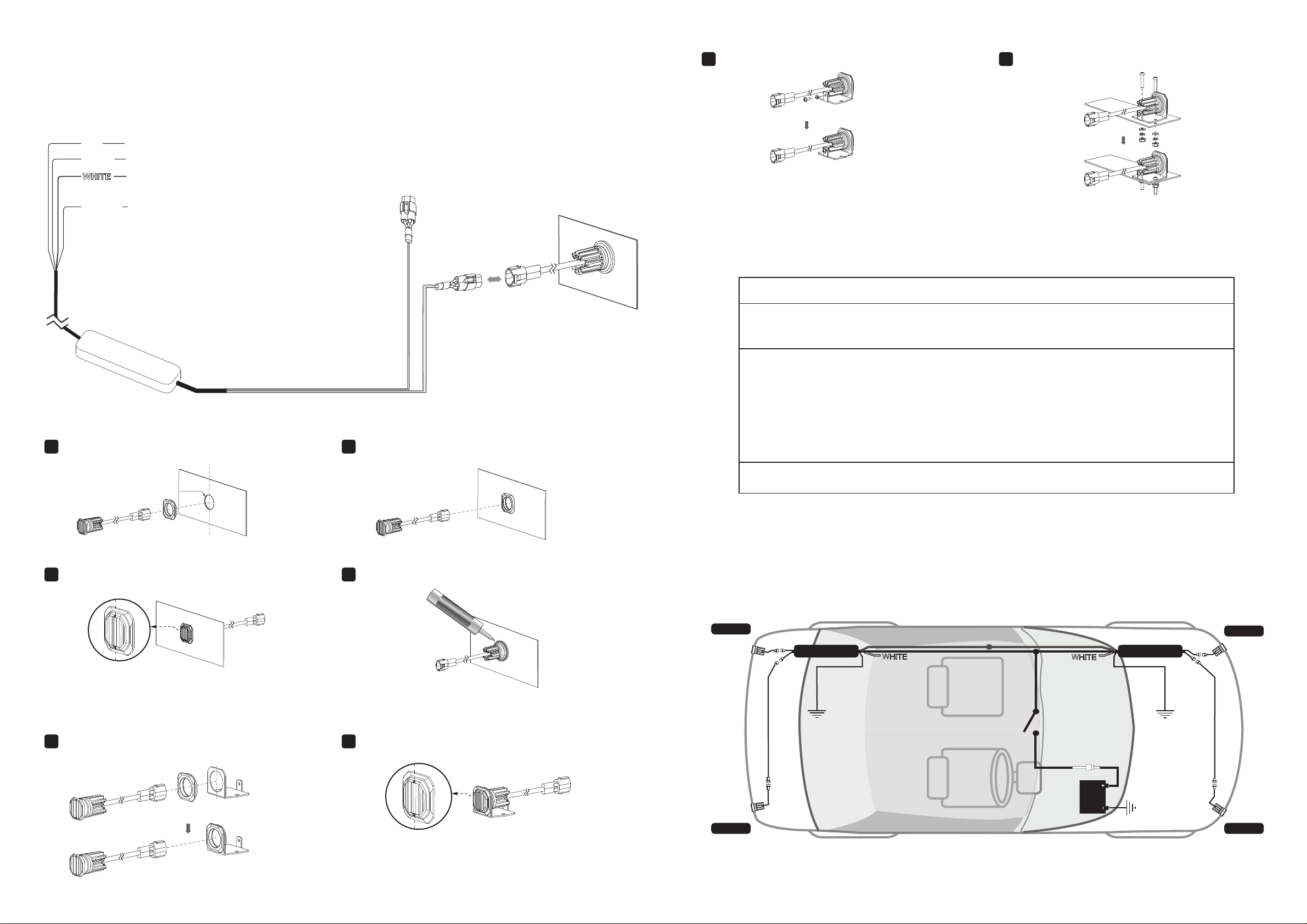
Installation & Mounting
SILICONE
SILICONE
1. Select location to mount LED CONTROLLER.
2. Use double-sided tape (or similar) and mount on clean surface.
3. Route RED and BLACK wires to vehicle power source.
4. Select desired Flash Pattern using YELLOW wire.
Secure LIGHTHEAD onto BRACKET with screw.
3
screw
Back side of
mounting bracket
Secure BRACKET onto mounting surface with screws.
4
screws
mounting
surface
RED
BLACK
To +VDC (fuse12V@3A / 24V@2A)
To Chassis Ground
For DIM Mode
Connect WHITE wire to +VDC for DIM Mode
YELLOW
For Synchronization & Flash Patterns
Connect YELLOW wires of all Kits together for synchronization
*All kits must be set at the same pattern
For Flash Modes:
1. Apply +VDC to RED and YELLOW wires simultaneously
to enter Flash mode.
2. Remove YELLOW wire from +VDC and momentarily
apply to +VDC to change Modes:
˙Mode 1 = Head1 alternate Head2
˙Mode 2 = Head1&2 flash simultaneously
3. Exit Flash mode by removing +VDC.
For Flash Pattern change, momentarily apply YELLOW wire to +VDC:
· once for next pattern · quickly three times for reset
NOTE: Make sure to cover all unused bare wires.
INSTALLATION - FLUSH MOUNT
Select mounting location and drill 1” (25.4mm) hole.
1
NOTE: recommended mounting
surface thickness is 0.8~2.0mm
Ø25.4mm
to lighthead or
extension cable
From the front side, install MOUNTING GROMMET
2
into the hole, and then insert LIGHTHEAD.
Back side of
mounting surface
Power Requirements
CURRENT DRAW
Maximum: 2.4 amp @12VDC / 1.2 amp @24VDC
Average: 1.2 amp @12VDC / 0.6 amp @24VDC
FLASH PATTERN SELECTION
Any one of the 14 Flash Patterns may be selected by using the yellow wire to scroll through the
patterns. Momentarily apply the yellow wire to +VDC to switch to the next pattern. The following
patterns are available.
1. Single-2Hz
2. Double-R65
3. Triple-2Hz
4. Quad-2Hz
5. Random
6. Single
7. Double
NOTE: Flash Pattern #2 must be selected to conform with requirements of ECE Regulation 65.
A single lighthead is approved, so both simultaneous and alternating flashing meets R65.
mounting
surface
8. Quad
9. Quint
10. Mega
11. Ultra
12. Single-Quad
13. Single H/L
14. Steady
Front side of
mounting
lighthead
Ensure that triangle marks on the lens are aligned vertically.
3
grommet
mounting surface
lighthead
Where necessary, apply silicone on the back side to prevent
4
from rotating.
lens
Front side of
mounting surface
silicone
(user supplier)
to controller or
extension cable
INSTALLATION - BRACKET MOUNT (sold-separately)
From the front side, install MOUNTING GROMMET
1
into the hole, and then insert LIGHTHEAD.
mounting
grommet
lighthead
Front side of
mounting bracket
Ensure that triangle marks on the lens are aligned vertically.
2
lens
Front side of
mounting surface
Back side of
mounting surface
WIRING 2 KITS TOGETHER
Below is an illustration of wiring 2 kits together. In this configuration, Heads 1&3
flash together and Heads 2&4 flash together.
· If Flash Mode 1 is selected: Heads 1&3 will alternate with Heads 2&4.
· If Flash Mode 2 is selected: all Heads 1&2&3&4 will flash simultaneously.
*refer to Flash Patterns chart on opposite page.
HEAD 3
YELLOW
RED
BLACK
EXTENSION CABLE
to GND
ON/OFF
HEAD 4
NOTE: To have Heads 1&4 alternate with 2&3,
simply reverse the lighthead outlets on one of the
Controllers; (both kits must be in Flash Mode 1).
HEAD 1
Unit1 Controller Unit2 Controller
BLACK
EXTENSION CABLE
to GND
12V@3A / 24V@2A FUSE
(user-supplied)
CHASSIS
GROUND
HEAD 2
NOTE: Controller mounting area varies from vehicle to vehicle. (Illustration not to scale)
2
3
 Loading...