

Page 1
Specifications
4ea. XT4
6ea. XT3
Input Voltage
12VDC
12VDC
Peak Input Current
2 Amp
2 Amp
Output Power
12 W
24 W
Flash Patterns
25
12
Fuse (customer supplied)
3A
3A
IMPORTANT:
INSTALLER: This manual must be delivered to the end user of this equipment
Read all instructions and warnings before installing and using.
CODE 3, Inc. a Division
of ECCO Safety Group
INSTALLATION &
OPERATION
MANUAL
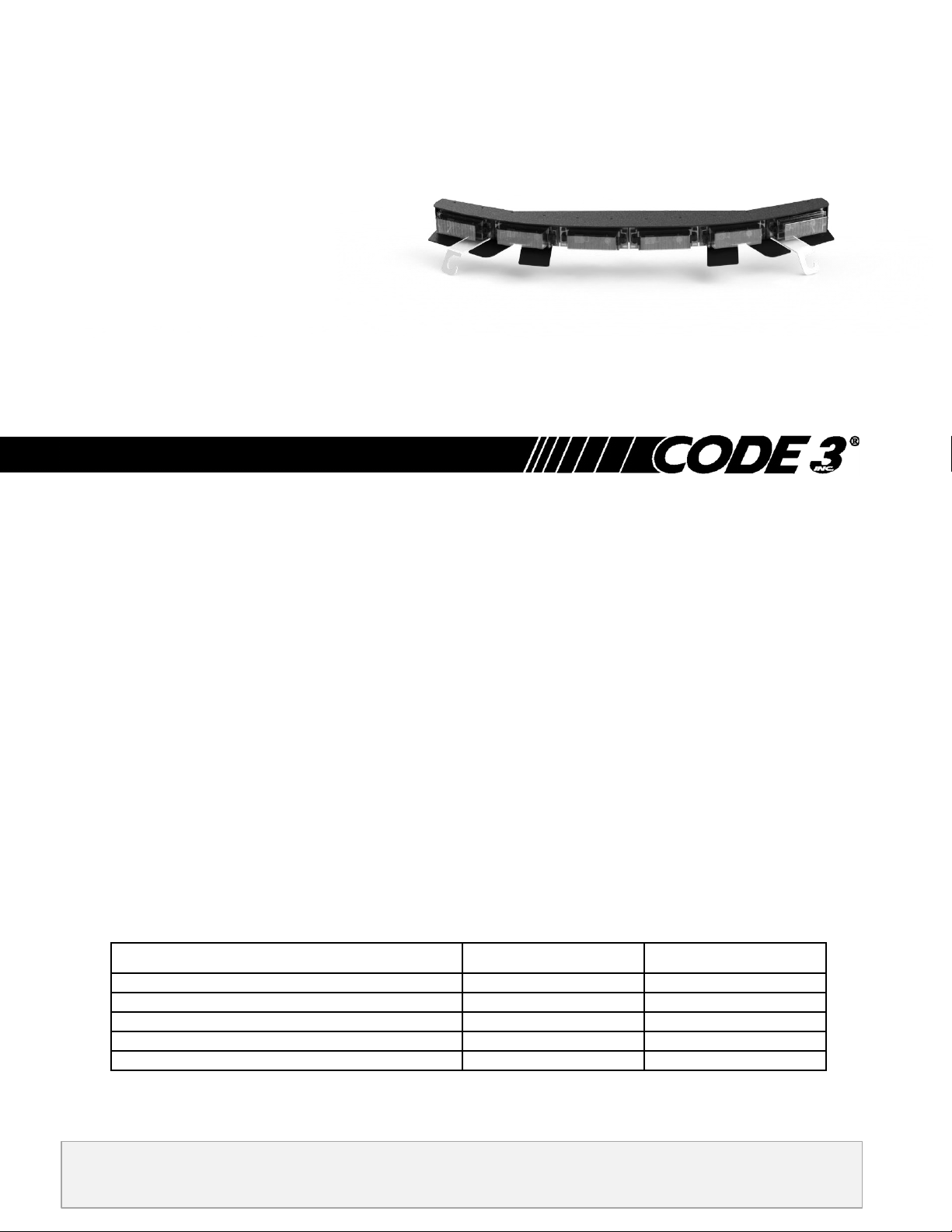
2014+ Harley Davidson Electra Glide - Supervisor
HARLEY DAVIDSON SUPERVISOR INSTALLATION
Table of Contents:
Installation of Supervisor ........................................................................................... 2
Wire Connections ...................................................................................................................................... 2
Installation notes ....................................................................................................... 3
Warranty Information ................................................................................................. 4
Page 2

Installation:
FIG. 1
1. Loosen two outboard windshield screws from faring on the bike
2. Loosen center screw from faring on the bike
3. Install two mounting brackets onto outboard faring screws (FIG. 1)
4. Place Supervisor unit over loosened brackets
5. Feed 10-32 Screw through back of supervisor and screw into bracket (leave loose).
6.
Retighten windshield to faring using three screw
7.
Tighten Supervisor against windshield
Wire Connection:
1. Connect red & white wire to 12V power supply.
2. Connect black wire to ground.
3. Factory Default Flash pattern is A1&A2 – Five Flash. To change light head flash pattern apply and remove
ground to blue wire prior to installation.
Flash Patterns - Single Color: XT3
PA1- Five Flash P1 PA7- Single Flash P1
PA2- Five Flash P2 PA8- Single Flash P2
PA3- Quad Flash P1 PA9- Triple Flash P1
PA4- Quad Flash P2 PA10- Triple Flash P2
PA5- Double Flash P1 PA11- Steady Burn
PA6- Double Flash P2 PA12- OFF
Flash Patterns – Multi-Color: XT4
PA1 - LAMP-1 Single Flash 75 Sim P1 PA14 - LAMP-2 Double Flash 75 Sim P2
PA2 - LAMP-1 Single Flash 75 Sim P2 PA15 - Dual-Lamp ALT Double Flash 75 Sim P1
PA3 - LAMP-2 Single Flash 75 Sim P1 PA16 - Dual-Lamp ALT Double Flash 75 Sim P2
PA4 - LAMP-2 Single Flash 75 Sim P2 PA17 - Dual-Lamp ALT Quad Flash 75 Sim P1
PA5 - LAMP-1 CA T13 75FPM Single Flash Sim P1 PA18 - Dual-Lamp ALT Quad Flash 75 Sim P2
PA6 - LAMP-1 CA T13 75FPM Single Flash Sim P2 PA19 - LAMP-1 ECE R65 120FPM Single Flash Sim P1
PA7 - LAMP-2 CA T13 75FPM Single Flash Sim P1 PA20 - LAMP-1 ECE R65 120FPM Single Flash Sim P2
PA8 - LAMP-2 CA T13 75FPM Single Flash Sim P2 PA21 - LAMP-2 ECE R65 120FPM Single Flash Sim P1
PA9 - Dual-Lamp ALT Single Flash 75 Sim P1 PA22 - LAMP-2 ECE R65 120FPM Single Flash Sim P2
PA10 - Dual-Lamp ALT Single Flash 75 Sim P2 PA23 - Dual-Lamp ALT ECE R65 120FPM Single Flash Sim P1
PA11 - LAMP-1 Double Flash 75 Sim P1 PA24 - Dual-Lamp ALT ECE R65 120FPM Single Flash Sim P2
PA12 - LAMP-1 Double Flash 75 Sim P2 PA25 - OFF
PA13 - LAMP-2 Double Flash 75 Sim P1
2
Page 3

Notes:
3
Page 4

L
re
n
!
CODE 3, Inc. a Division
of ECCO Safety Group
WARNING!
Larger wires and tight connections will provide longer service life for components. For high current wires it is highly
recommended that terminal blocks or soldered connections be used with shrink tubing to protect the connections. Do
not use insulation displacement connectors (e.g. 3M Scotchlock type connectors). Route wiring using grommets and
sealant when passing through compartment walls. Minimize the number of splices to reduce voltage drop. High
ambient temperatures (e.g. under hood) will significantly reduce the current carrying capacity of wires, fuses, and
circuit breakers. Use "SXL" type wire in engine compartment. All wiring should conform to the minimum wire size and
other recommendations of the manufacturer and be protected from moving parts and hot surfaces. Looms, grommets,
cable ties, and similar installation hardware should be used to anchor and protect all wiring. Fuses or circuit breakers
should be located as close to the power takeoff points as possible and properly sized to protect the wiring and devices.
Particular attention should be paid to the location and method of making electrical connections and splices to protect
these points from corrosion and loss of conductivity. Ground terminations should only be made to substantial chassis
components, preferably directly to the vehicle battery. The user should install a fuse sized to approximately 125% of
the maximum Amp capacity in the supply line to protect against short circuits. For example, a 30 Amp fuse should
carry a maximum of 24 Amps. DO NOT USE 1/4" DIAMETER GLASS FUSES AS THEY ARE NOT SUITABLE FOR
CONTINUOUS DUTY IN SIZES ABOVE 15 AMPS. Circuit breakers are very sensitive to high temperatures and will
"false trip" when mounted in hot environments or operated close to their capacity.
Wear hearing protection when testing, Use siren only for emergency response, Roll up windows when siren is
operating, Avoid exposure to the siren sound outside of vehicle.
WARRANTY
Code 3, ®Inc.'s emergency devices are tested and found to be operational at the time of manufacture. Provided they are installed
and
operated in accordance with manufacturer's recommendations, Code 3, Inc. guarantees all parts and components except the
lamps to a period of 1 year (unless otherwise expressed) from the date of purchase or delivery, whichever is later. Units
demonstrated to be defective within the warranty period will be repaired or replaced at the factory service center at no cost.
Use of lamp or other electrical load of wattage higher than installed or recommended by the factory, or use of inappropriate or
inadequate wiring or circuit protection causes this warranty to become void. Failure or destruction of the product resulting from abuse
or unusual use and/or accidents is not covered by this warranty. Code 3, Inc. shall in no way be liable for other damages including
consequential, indirect or special damages whether loss is due to negligence or breach of warranty.
CODE 3, INC. MAKES NO OTHER EXPRESS OR IMPLIED WARRANTY INCLUDING, WITHOUT LIMITATION, WARRANTIES
Code 3
OF FITNESS OR MERCHANTABILITY, WITH RESPECT TO THIS PRODUCT.
PRODUCT RETURNS
If a product must be returned for repair or replacement*, please contact our factory to obtain a R e t urn Goods Authorization Number
(RGA number) before you ship the product to Code 3, Inc. Write the RGA number clearly on the package near the mailing label. Be sure you
use sufficient packing materials to avoid damage to the product being returned while in transit.
*Code 3, Inc. reserves the right to repair or replace at its discretion. Code 3, Inc. assumes no responsibility or liability for expenses incurred for the removal and /or reinstallation of products requiring
service and/or repair; nor for the packaging, handling, and shipping: nor for the handling of products return to sender after the service has been rendered.
PROBLEMS OR QUESTIONS? CALL OUR TECHNICAL ASSISTANCE HOTLINE (314) 996-2800
WWW.CODE3PSE.COM
®
a registered trademark of Code 3, Inc., a subsidiary of Public Safety Equipment, Inc.
St. Louis, Missouri 63114-2029—USA
Ph. (314) 426-2700 Fax (314) 426-1337
Part No. T57272 Rev. 0 12/2013
Code 3®, Inc.
10986 N. Warson Road
©2013 Code 3, Inc.
4
 Loading...