

Page 1
INSTALLATION
& OPERATION
MANUAL
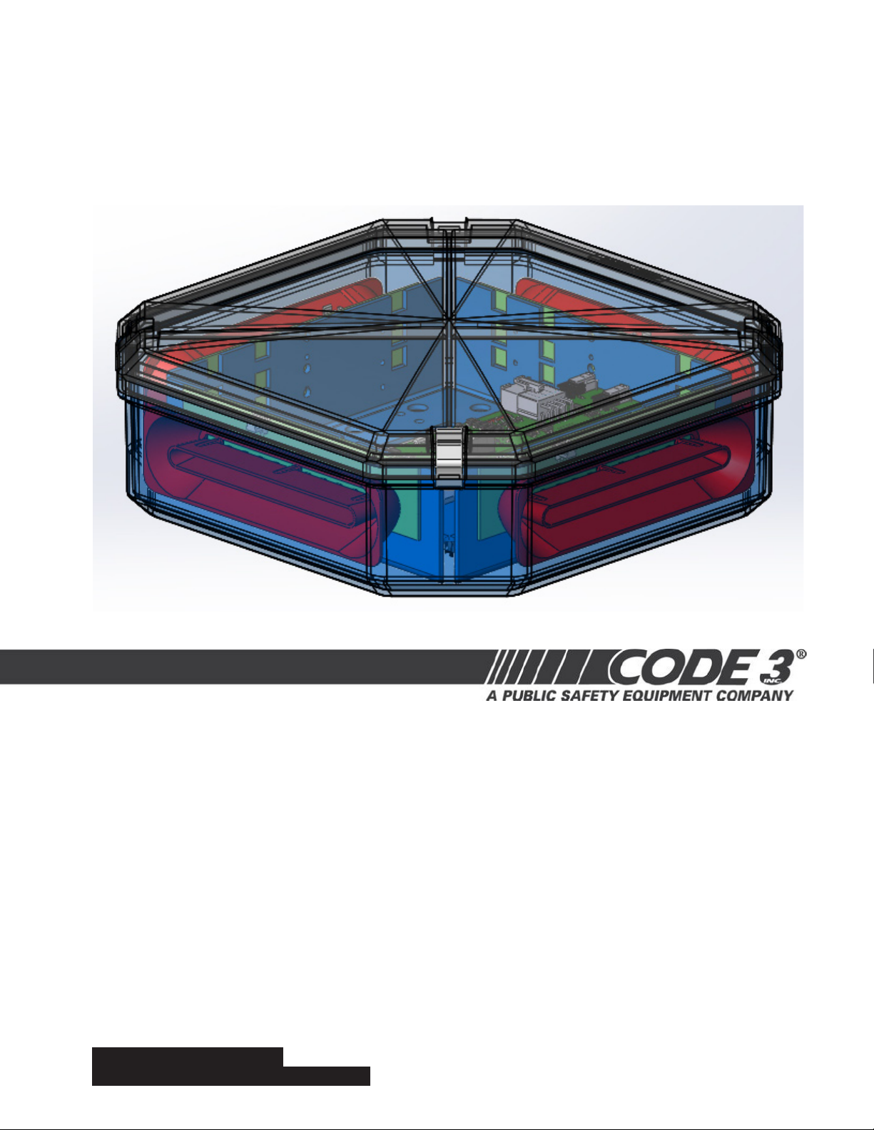
DuoBeam II
IMPORTANT:
CONTENTS:
Introduction..... .............................................................................2
Unpacking & Pre-Installation........................................................2
Installation & Mounting.................................................................2
Wiring & Fusing............................................................................4
LED Lighthead Description & Pattern Change.............................5
Parts List......................................................................................8
Dimensions & Specications......................................................11
Maintenance...............................................................................11
Warranty.....................................................................................12
Read all instructions and warnings before installing and using.
This manual must be delivered to the end user of this equipment.
INSTALLER:
1
Page 2
Introduction
The LED DuoBeam IITM uses state of the art LEDs and optics to provide superior optical output. The rugged
design and long life capabilities make it virtually maintenance free. When properly congured, the Duo-Beam
will exceed SAE Class 1 and California Title 13 requirements.
The use of this or any warning device does not ensure that all drivers can or will observe or react to
an emergency warning signal. Never take the right-of-way for granted. It is your responsibility to be
sure you can proceed safely before entering an intersection, driving against trafc, responding at a
high rate of speed, or walking on or around trafc lanes.
The effectiveness of this warning device is highly dependent upon correct mounting and wiring.
Read and follow the manufacturer’s instructions before installing or using this device. The vehicle
operator should insure daily that all features of the device operate correctly. In use, the vehicle
!
Warning!
operator should insure the projection of the warning signal is not blocked by vehicle components (i.e.:
open trunks or compartment doors), people, vehicles, or other obstructions.
This equipment is intended for use by authorized personnel only. It is the user’s responsibility to
understand and obey all laws regarding emergency warning devices. The user should check all ap-
plicable city, state and federal laws and regulations.
Code 3, Inc., assumes no liability for any loss resulting from the use of this warning device.
Proper installation is vital to the performance of this warning device and the safe operation of the
emergency vehicle. It is important to recognize that the operator of the emergency vehicle is under
psychological and physiological stress caused by the emergency situation. The warning device
should be installed in such a manner as to: A) Not reduce the output performance of the system, B)
Place the controls within convenient reach of the operator so that he can operate the system without
losing eye contact with the roadway.
Emergency warning devices often require high electrical voltages and/or currents. Properly protect
and use caution around live electrical connections. Grounding or shorting of electrical connections
can cause high current arcing, which can cause personal injury and/or severe vehicle damage,
including re.
PROPER INSTALLATION COMBINED WITH OPERATOR TRAINING IN THE PROPER USE OF
EMERGENCY WARNING DEVICES IS ESSENTIAL TO INSURE THE SAFETY OF EMERGENCY
PERSONNEL AND THE PUBLIC.
Unpacking & Pre-installation
Carefully remove the light bar and place it on a at surface, taking care not to scratch the lenses or damage
the cable coming out of the bottom. Examine the unit for transit damage, broken lamps, etc. Report any
damage to the carrier and keep the shipping carton.
The LED DuoBeam IITM is built to operate on 12 volt D.C. negative ground (earth) vehicles. If you have an
electrical system other than 12 volt D.C. negative ground (earth) contact the factory.
Installation & Mounting
**For orientation purposes, the DuoBeam was built with the carriage bolt track running from left to right -
(not front to back).
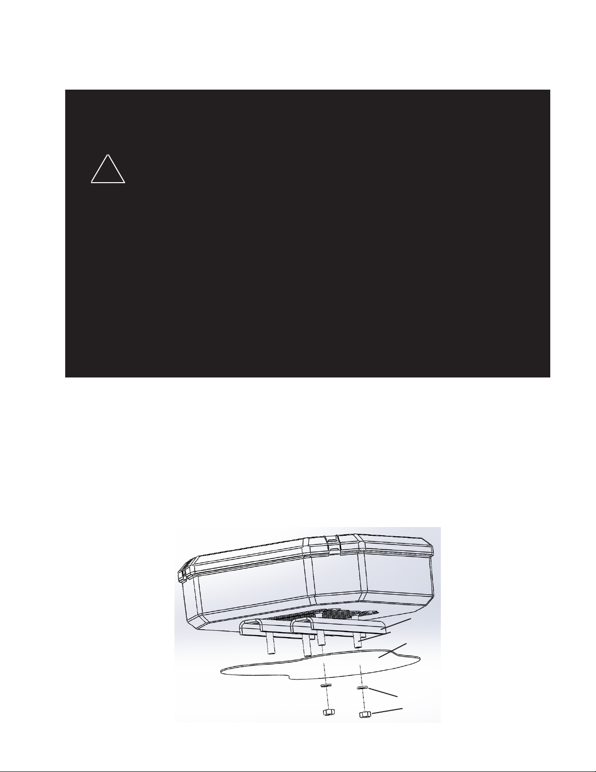
FLUSH MOUNT
Insert carriage bolts into
track. Place spacer over
bolts as shown to the
right. Align bolts with
pre-drilled holes in vehicle's surface. Place lock
washer and nut on bolt
and tighten until snug.
MOUNTING SPACER (S50179)
5/16-18 X 1 1/2" CARRIAGE BOLT (PN 240)
VEHICLE MOUNTING SURFACE
5/16" SPLIT LOCK WASHER (PN 245)
5/16-18 SS HEX NUT (PN 244)
NOTE: Spacer must be used to prevent water from entering the bar.
2
Page 3
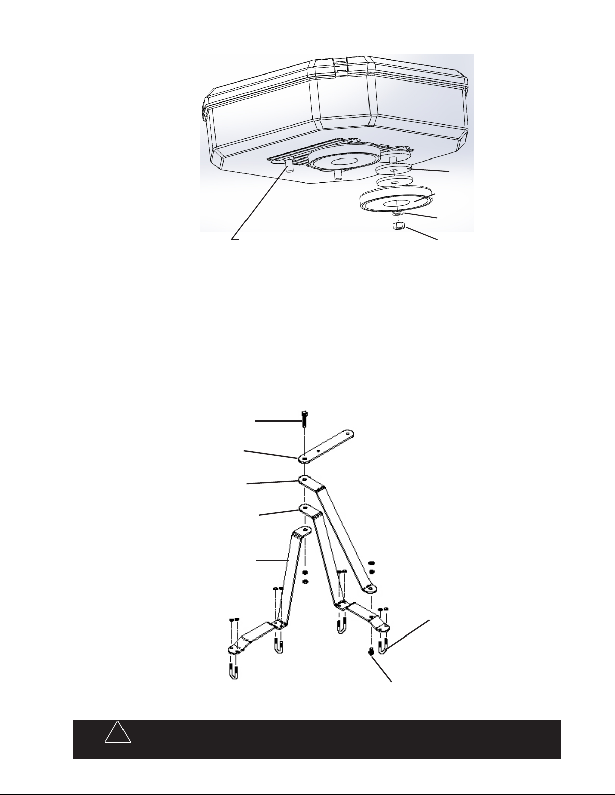
MAGNETIC MOUNT
Insert carriage bolts into
track. Place molded shims
over bolts as shown. Attach
magnetic base over bolts.
Place lock washer and nut
on bolt then tighten until
snug.
MOLDED SHIM (PN 1064)
RB 80 MAGNETIC BASE (PN 499)
5/16" SPLIT WASHER (PN 245)
5/16-18 X 1 1/2" CARRIAGE BOLT (PN 240)
5/16-18 SS HEX NUT (PN 244)
MIRROR MOUNT BRACKET
1. Assemble the brackets, tighten the 3/8 bolt but leave the 7/16 bolt nger tight at this time.
2. Position bracket assembly on top mirror supports, bracket A on rear support and bracket B on front sup-
port. Note: some mirror designs require reversing bracket A and B. Rotate bracket A as necessary to get
the best t. Some additional bending of brackets may be necessary in some cases to achieve a satisfactory t.
3. Attach bracket assembly to mirror supports with U-bolts, position bracket assembly as desired and tighten
U-bolts. The Duo Beam mounting bracket should be parallel to the ground.
7/16" LONG BOLT
T03807 MOUNTING BRACKET
T03804 MOUNTING BRACKET
T07595 MOUNTING BRACKET
T07595 (IMMBH) OR T03802 (MMBH)
MOUNTING BRACKET
!
Warning!
Utilizing non-factory supplied screws and/or mounting brackets and/or the improper
number of screws may result in loss of warranty coverage on the equipment.
U-BOLT
3/8" LONG BOLT
3
Page 4

Wiring & Fusing
Larger wires and tight connections will provide longer service life for components. For high
current wires it is highly recommended that terminal blocks or soldered connections be used
with shrink tubing to protect the connections. Do not use insulation displacement connectors
(e.g. 3M® Scotchlock type connectors). Route wiring using grommets and sealant when pass-
!
Warning!
One of two cable types will be installed in the DuoBeam:
ing through compartment walls. Minimize the number of splices to reduce voltage drop. High
ambient temperatures (e.g. underhood) will signicantly reduce the current carrying capacity of
wires, fuses, and circuit breakers. Use "SXL" type wire in engine compartment. All wiring should
conform to the minimum wire size and other recommendations of the manufacturer and be pro-
tected from moving parts and hot surfaces. Looms, grommets, cable ties, and similar installation
hardware should be used to anchor and protect all wiring. Fuses or circuit breakers should be
located as close to the power takeoff points as possible and properly sized to protect the wiring
and devices. Particular attention should be paid to the location and method of making electrical
connections and splices to protect these points from corrosion and loss of conductivity. Ground
terminations should only be made to substantial chassis components, preferably directly to the
vehicle battery. The user should install a fuse sized to approximately 125% of the maximum Amp
capacity in the supply line to protect against short circuits. For example, a 30 Amp fuse should
carry a maximum of 24 Amps. DO NOT USE 1/4" DIAMETER GLASS FUSES AS THEY ARE
NOT SUITABLE FOR CONTINUOUS DUTY IN SIZES ABOVE 15 AMPS. Circuit breakers are
very sensitive to high temperatures and will "false trip" when mounted in hot environments or
operated close to their capacity.
2 conductor• (1 red & 1 black) - This cable is used when the light heads have an integrated asher
installed. The light heads ash independently. The red conductor should be connected to power
(+12VDC) via a switch or controller of some kind and the black conductor should be connected to
ground.
7 conductor• - This cable is used when there is a central controller installed. All TriCoreTM models
and most multi-color models will employ a CC. These models will require a somewhat more sophisticated method of control (switchbox or siren with lighting controls) as more options are available.
Further explanation can be found starting on Page 6 of this manual.
LED Fusing Considerations
Although the average current draw per LED module is very low, the instantaneous peak current to a module can be higher during low voltage conditions. To avoid prematurely blowing of ATO style fuses or tripping
breakers it is recommended the following rule-of-thumb be used to size fuses or breakers. This is especially
important in light bars with many LED modules running off a single fused source. It is always best to have
20-25% head room in calculating for fusing. Please use the values below to calculate fuse values for DuoBeam installation.
For PriZm IITM lightheads:
REF8 - 1.0 x (number of lightheads being fused)
REF12 - 1.5 x (number of lightheads being fused)
Example:
DuoBeam with (4) REF12 lightheads - 4*1.5A = 6A minimum
For TorusTM lightheads:
TRS6 - 1.0 x (number of lightheads being fused)
For TriCoreTM lightheads:
TC6 - 2.0 x (number of lightheads being fused)
4
Page 5

LED Lighthead Description and Pattern Change
The DuoBeam can be populated with one of three different types of Code 3 LED's - PriZm IITM, TorusTM and
TriCore
do not require a separate asher, however, all models CAN be controlled by a asher.
TM
technologies. The PriZmTM and TorusTM lightheads are available with an integrated ash control and
!
Warning!
PriZm IITM(Integratedasherinlighthead)
Flash Pattern Description
1. Cycle Flash (DEFAULT)-------------Cycles through various patterns @ 70 fpm
2. NFPA Quad Flash 80 FPM----------Four Pulses per ash @ 80 fpm
3. Steadyburn------------------------------Steady-Burn
4. Five Flash 150 FPM------------------Five Pulses per ash @ 150 fpm
5. Quad Flash 150 FPM-----------------Four Pulses per ash @ 150 fpm
6. Triple Flash 150 FPM ----------------Three Pulses per ash @ 150 fpm
7. Double Flash 150 FPM---------------Two Pulses per ash @ 150 fpm
8. Single Flash 150 FPM----------------One Pulse per ash @ 150 fpm
9. Single Flash 250 FPM----------------One Pulse per ash @ 250 fpm
10. Single Flash 375 FPM---------------One Pulse per ash @ 375 fpm
11. Triple Pop Flash 75 FPM------------Three Pulses per ash ( 2 equal, 1 extended) @ 75 fpm
12. Quad Pop Flash 75 FPM------------Four Pulses per ash ( 3 equal, 1 extended) @ 75 fpm
13. Single Flash 75 FPM------------------One Pulse per ash @ 75 fpm
14. Double Flash 75 FPM-----------------Two Pulses per ash @ 75 fpm
15. Triple Flash 70 FPM ------------------Three Pulses per ash @ 70 fpm
16. Quad Flash 70 FPM ------------------Four Pulses per ash @ 70 fpm
17. Five Flash 70 FPM --------------------Five Pulses per ash @ 70 fpm
18. Mod Flash
19. Action Flash
This Product contains high intensity LED devices. To prevent eye damage,
DO NOT stare into light beam at close range.
The ash pattern can be changed by shorting the J4 pad with a wire or blade of
a screwdriver (shown below). The lighthead can be reset to the default by short-
ing the J4 pad for greater than 5 seconds and then releasing
Momentarily short and
release to change patterns
Located on front of
Integrated PCB/Light Engine
Reectorremovedforclarity
5
Page 6

TorusTM(Integratedasherinlighthead)
00
1
1
2
9
9
9 9
21
LOC
LOC
LOC
9
9
9 9
121
2
3
Flash Pattern Description
1. Cycle Flash (DEFAULT)--------------Cycles through various patterns @ 70 fpm
2. NFPA Quad Flash 80 FPM-----------Four Pulses per ash @ 80 fpm
3. Quad Flash 70 FPM--------------------Four Pulses per ash @ 70 fpm
4. Steadyburn-------------------------------Steady-Burn
5. Five Flash 70 FPM---------------------Five Pulses per ash @ 70 fpm
6. Triple Flash 70 FPM ------------------Three Pulses per ash @ 70 fpm
7. Double Flash 70 FPM-----------------Two Pulses per ash @ 70 fpm
8. Single Flash 70 FPM------------------One Pulse per ash @ 70 fpm
9. Quad Pop Flash 70 FPM-------------Four Pulses per ash ( 3 equal, 1 extended) @ 70 fpm
10. Triple Pop Flash 70 FPM------------Three Pulses per ash ( 2 equal, 1 extended) @ 70 fpm
11. Mod Flash
12. Cycle Flash 150 FPM-----------------Cycles through various patterns @ 150 fpm
13. Five Flash 150 FPM-------------------Five Pulses per ash @ 150 fpm
14. Quad Flash 150 FPM------------------Four Pulses per ash @ 150 fpm
15. Triple Flash 150 FPM -----------------Three Pulses per ash @ 150 fpm
16. Double Flash 150 FPM---------------Two Pulses per ash @ 150 fpm
17. Single Flash 150 FPM----------------One Pulse per ash @ 150 fpm
18. Single Flash 250 FPM----------------One Pulse per ash @ 250 fpm
19. Single Flash 375 FPM------------------One Pulse per ash @ 375 fpm
The ash pattern can be changed by shorting the J4 pad with a wire or blade of
a screwdriver (shown below). The lighthead can be reset to the default by short-
ing the J4 pad for greater than 5 seconds and then releasing
Momentarily short and
release to change patterns
Opticremovedforclarity
Located on front of
Integrated PCB/Light Engine
PriZm IITM, TorusTM, and TriCoreTM modules with Central Controller
The following table shows the functions of the conductors of the 7 conductor cable. Please note that the CC
must be powered (red conductor must have +12VDC) before any of the functions can be enabled. The blue,
orange, and yellow ash activation conductors, when energized, enable the lightheads to be ashed.
Note: All control inputs are +power enabled.
ControlInputFunctionDenition
Wire Color Function Description
BLUE (primary)
ORANGE (secondary)
Flash Activation
YELLOW (multi-color)
WHITE Dimming Dims lighthead modules
GREEN Pattern Select Light Bar Flash Pattern Select Wire & Diagnostic Test
BLACK Ground Ground
RED Power +12V Input Supply
Energizes light heads per the pattern chosen by the
end user or, if left unchanged, per the defaults set at the
factory (see table of ash patterns).
6
Page 7

Progressivevs.IndependentSwitching
Depending on how the blue, orange, and yellow activation wires are connected, different levels of control are
possible. For example, activating the blue wire allows a ash pattern to be set. Activating the blue + orange
wires allows a different pattern to be set. Activating only the orange wire allows yet another to be set. Seven
combinations are possible.
Flash Pattern Selection (Very important - read carefully)
Energize (+12VDC) to the red wire and ground the black wire. Energize the activation wires desired to begin
ashing the lightheads. Observe the ash pattern (Default). Change the ash pattern as follows:
If touched for 0-2 seconds, the lighthead will steady burn dimly and the next pattern in line will begin when
the green wire is deactivated.
If touched for 2-4 seconds, the lightheads will shut off and the previous pattern will begin when the green
wire is deactivated.
If touched for more than 4 seconds, the lightheads will shut off and then turn on again. All patterns will
be reset to factory default.
The pattern that is selected will be stored even when power is removed.
There are 16 patterns for single color models and 47 for multi-color models. Alternating refers to a pair of
lights ashing together while simultaneous refers to all heads (of the same color) ashing together.
FP# Single Color Multi-Color FP# Multi-Color
1 Cycle Flash Sim. 70 fpm Cycle Flash Sim. 70 fpm 25 Variable Single Alt. (primary)
2 Cycle Flash Alt. 70 fpm Cycle Flash Alt. 70 fpm 26 Cycle Flash Sim. 150 fpm (primary)
3 NFPA Quad Sim. 80 fpm NFPA Quad Sim. 80 fpm 27 Cycle Flash Alt. 150 fpm (primary)
4 NFPA Quad Alt. 80 fpm NFPA Quad Alt. 80 fpm 28 Single Sim. 250 fpm (primary)
5 Triple Simultaneous 70 fpm Triple Simultaneous 70 fpm 29 Single Alternating 250 fpm (primary)
6 Triple Alternating 70 fpm Triple Alternating 70 fpm 30 Rotate (primary)
7 Double Simultaneous 70 fpm Double Simultaneous 70 fpm 31 Cruise (primary)
8 Double Alternating 70 fpm Double Alternating 70 fpm 32 Cycle Flash Sim. 70 fpm (secondary)
9 Variable Single Sim. Variable Single Sim. 33 Cycle Flash Alt. 70 fpm (secondary)
10 Variable Single Alt Variable Single Alt 34 NFPA Quad Sim. 80 fpm (secondary)
11 Cycle Flash Sim. 150 fpm Cycle Flash Sim. 150 fpm 35 NFPA Quad Alt. 80 fpm (secondary)
12 Cycle Flash Alt. 150 fpm Cycle Flash Alt. 150 fpm 36 Triple Sim. 70 fpm (secondary)
13 Single Sim. 250 fpm Single Sim. 250 fpm 37 Triple Alt. 70 fpm (secondary)
14 Single Alternating 250 fpm Single Alternating 250 fpm 38 Double Sim. 70 fpm (secondary)
15 Rotate Rotate 39 Double Alt. 70 fpm (secondary)
16 Cruise Cycle Flash Sim. 70 fpm (primary) 40 Variable Single Sim. (secondary)
17 - Cycle Flash Alt. 70 fpm (primary) 41 Variable Single Alt (secondary)
18 - NFPA Quad Sim. 80 fpm (primary) 42 Cycle Flash Sim. 150 fpm (secondary)
19 - NFPA Quad Alt. 80 fpm (primary) 43 Cycle Flash Alt. 150 fpm (secondary)
20 - Triple Simultaneous 70 fpm (primary) 44 Single Sim. 250 fpm (secondary)
21 - Triple Alternating 70 fpm (primary) 45 Single Alternating 250 fpm (secondary)
22 - Double Simultaneous 70 fpm (primary) 46 Rotate (secondary)
23 - Double Alternating 70 fpm (primary) 47 Cruise (secondary)
24 - Variable Single Sim. (primary)
Diagnostic Test
There is also a diagnostic test that can be run using the Green pattern change wire. Apply +12V to the Green
wire (only). The lights will turn on one at a time and then turn off. Note that it can only be activated by apply-
ing power to the Green wire at start up. If the unit has been energized with any other wire, power needs to be
removed entirely from the light bar before applying power to the Green wire to enter into this mode again.
Dimming Operation
The DuoBeam can be operated in a low power "Dimming" mode. Dimming is controlled by connecting the
White wire to +12VDC. When Dimming is engaged, the lighheads will operate in reduced power mode.
7
Page 8
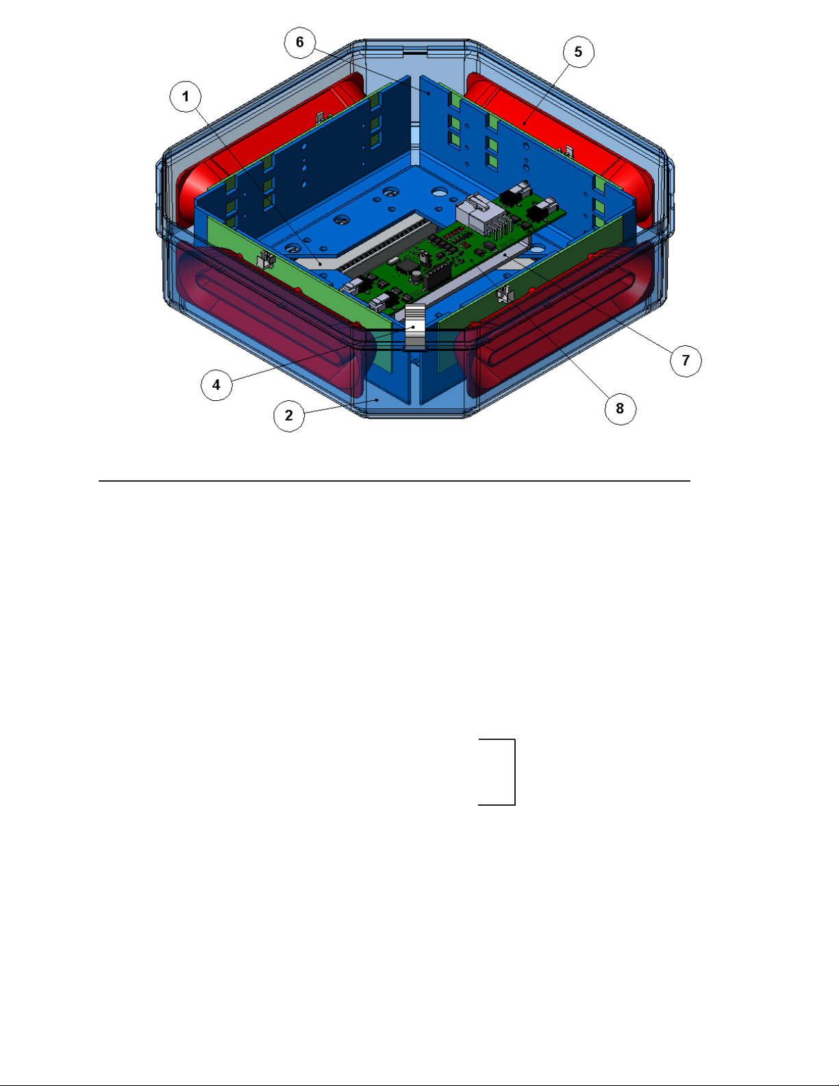
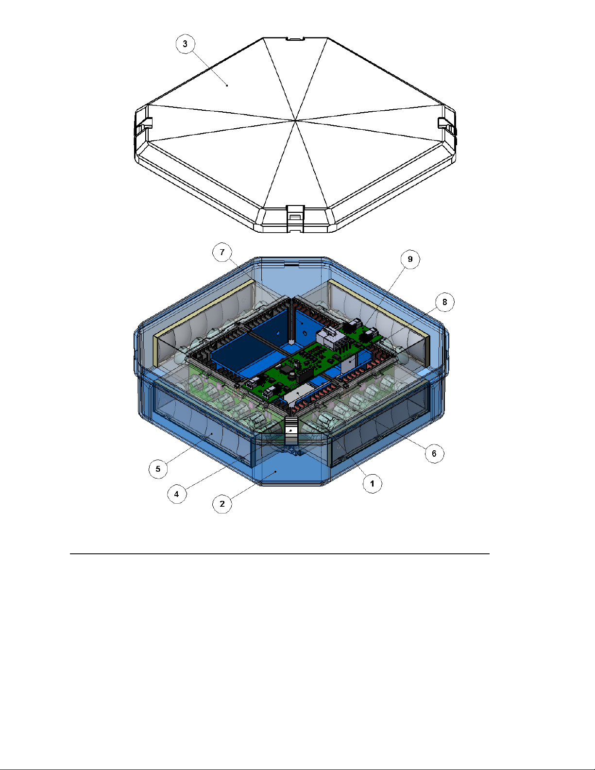
Parts List for DuoBeam with PriZm IITM Technology
IntegratedasherandCentralcontrolleravailable
Ref No. Description Part No.
1 Frame Extrusion Assembly S24358
2 Lower Lens
Clear T16541
Red T16542
Blue T16543
Amber T16544
3 Upper Lens (not shown for clarity)
Clear T16551
Red T16552
Blue T16553
Amber T16554
Black T16559
4 Lens Clip T01777
5 REF8 lighthead assembly (with integrated asher)
REF12 lighthead assembly (with integrated asher)
REF8 lighthead assembly (CC)
REF12 lighthead assembly (CC)
REF 22 dual color lighthead assembly (CC)
6 Lighthead Mounting Bracket (two required) S24354
Call Factory
7 Mounting Bracket for Central Controller (only on CC models) S24361
8 Central controller (CC) (only on CC models) T11568
9 Cable (not shown)
15' (for use with lightheads with integrated asher) T16568
35' (for use with lightheads with integrated asher) T16571
20' (CC) T51208
35' (CC) T16575
10 Output Harness (not shown)
Four output - Integrated asher T16565
Four output - (CC) T16566
8
Page 9
Parts List for DuoBeam with TriCore
TM
Technology
AvailableonlywithCentralController
Ref No. Description Part No.
****Unlessotherwisenoted,partsnumbersaresameasPriZmIImodelfrompreviouspage****
5 TC6 lighthead assembly - Contact factory for specic color
6 Base Locating Plate S24359
7 Lighthead Mounting Bracket (2 required) S24355
8 Mounting Bracket for Central Controller S24362
9 Central controller (CC) T11568
10 Cable (not shown)
20' (CC) T51208
35' (CC) T16575
11 Output Harness - 4 wire (CC)(not shown) T16566
9
Page 10
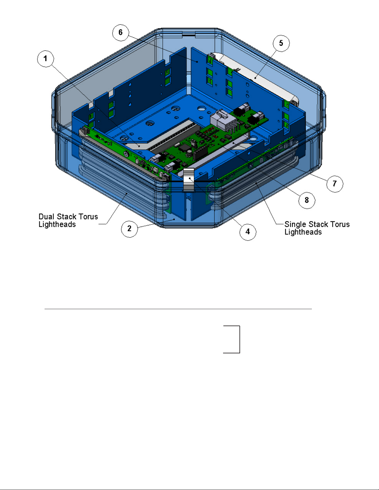
Parts List for DuoBeam with TorusTM technology
IntegratedasherandCentralcontrolleravailable
Ref No. Description Part No.
****Unlessotherwisenoted,partnumbersaresameasPriZmIIfrompreviouspage****
5 TRS6 lighthead assembly (with integrated asher)
TRS6 dual stack lighthead assembly (with integrated asher)
TRS6 lighthead assembly (CC)
TRS6 dual stack lighthead assembly (CC)
6 Lighthead Mounting Bracket (two required) S24354
7 Mounting Bracket for Central Controller (only on CC models) S24361
8 Central controller (CC) (only on CC models) T11568
9 Cable (not shown)
15' (for use with lightheads with integrated asher) T16568
35' (for use with lightheads with integrated asher) T16571
20' (CC) T51208
35' (CC) T16575
10 Output Harness (not shown)
Four output - Integrated asher T16565
Four output - (CC) T16566
Call Factory
10
Page 11
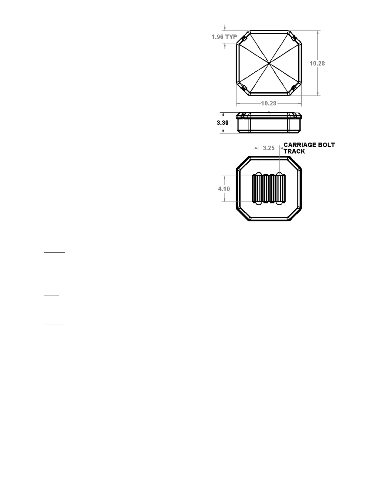
Dimensions&Specications
Physical Dimensions - 10.28"L x 10.28"W x 3.30"T
Average Weight - 6 lbs.
Materials:
Upper &Lower Lens - Polycarbonate
Extruded frame - Aluminum alloy
Electrical Data:
All lightheads have Reverse Polarity Protection installed
Operating Voltage: 10-16 VDC
Current Draw:
PriZm II
(for all colors)
REF8 - .75A average
REF12 - 1.0A average
REF22 - .95A average (only 11 LED's are on at one time)
Torus
(for all colors)
TRS6 - .5A average
TriCore
TC6 (Red & Amber) - 1A average
TC6 (Blue & White) - 1.2A average
TM
TM
TM
Maintenance
Lens Cleaning
Use plain water and a soft cloth, or Code 3 lens polish and a very soft paper towel or facial tissue. Because
plastic scratches easily, cleaning is recommended only when necessary (about every six months). Do not
subject the lenses to car washes that use brushes, as these will scratch the lenses.
11
Page 12

WARRANTY
Code 3, ®Inc.'s emergency devices are tested and found to be operational at the time
of manufacture. Provided they are installed and operated in accordance with manufacturer's
recommendations, Code 3, Inc. guarantees all parts and components except the lamps to a period
of 1 year, LED Lighthead modules to a period of 5 years (unless otherwise expressed) from the
date of purchase or delivery, whichever is later. Units demonstrated to be defective within the
warranty period will be repaired or replaced at the factory service center at no cost.
Use of lamp or other electrical load of a wattage higher than installed or recommended by
the factory, or use of inappropriate or inadequate wiring or circuit protection causes this warranty
to become void. Failure or destruction of the product resulting from abuse or unusual use and/
or accidents is not covered by this warranty. Code 3, Inc. shall in no way be liable for other
damages including consequential, indirect or special damages whether loss is due to negligence
or breach of warranty.
CODE 3, INC. MAKES NO OTHER ExPRESS OR IMPLIED WARRANTY INCLUDING, WITHOUT LIMITATION, WARRANTIES OF FITNESS OR MERCHANTABILITY, WITH
RESPECT TO THIS PRODUCT.
PRODUCT RETURNS
If a product must be returned for repair or replacement*, please contact our factory to
obtain a Return Goods Authorization Number (RGA number) before you ship the product to
Code 3, Inc. Write the RGA number clearly on the package near the mailing label. Be sure
you use sufcient packing materials to avoid damage to the product being returned while in
transit.
*Code 3, Inc. reserves the right to repair or replace at its discretion. Code 3, Inc. assumes no responsibility or liability for expenses incurred
for the removal and /or reinstallation of products requiring service and/or repair.; nor for the packaging, handling, and shipping: nor for the handling of
products return to sender after the service has been rendered.
PROBLEMS OR QUESTIONS? CALL OUR TECHNICAL ASSISTANCE HOTLINE (314) 996-2800
WWW.CODE3PSE.COM
Code 3® is a registered trademark of Code 3, Inc., a subsidiary of Public Safety Equipment, Inc.
12
Code 3®, Inc.
St. Louis, Missouri 63114-2029—USA
Ph. (314) 426-2700 Fax (314) 426-1337
10986 N. Warson Road
Part No. T16572 REV. 0 08/2012
©2012 Code 3, Inc
 Loading...