

Page 1
INSTALLATION GUIDE
1
DEUCE
DUAL HEAD W600
TECHNICAL SPECIFICATIONS
INPUT VOLTAGE ........................10 to 30 Volts DC.
INPUT CURRENT .......................0.5A @ 12.8V, 0.45A @ 25.6V
LIGHT OUTPUT ...........................AMBER: 160+ LUMENS
BLUE: 155+ LUMENS
RED: 123+ LUMENS
WHITE: 660+ LUMENS
CABLE LENGTH ..........................7 FT. (HEAD A), 4FT. (HEAD B)
LED ELEMENTS ..........................4 (EACH HEAD)
FLASH PATTERNS ......................16 (8 Standard, 8 optional cycle)
MAX NUMBER OF SYNC’D HEADS ... 64
WARRANTY PERIOD ..................5 YEARS
DIMENSIONS
1.28"
0.875"
1.50"
4.89"
LED HEAD
HEAD A
HEAD B
"59.0
0.150"
0.980"
1.50"
0.59"
833 W. Diamond St Boise, Idaho 83705
TEL: 888-844-6682 www.strobe.com
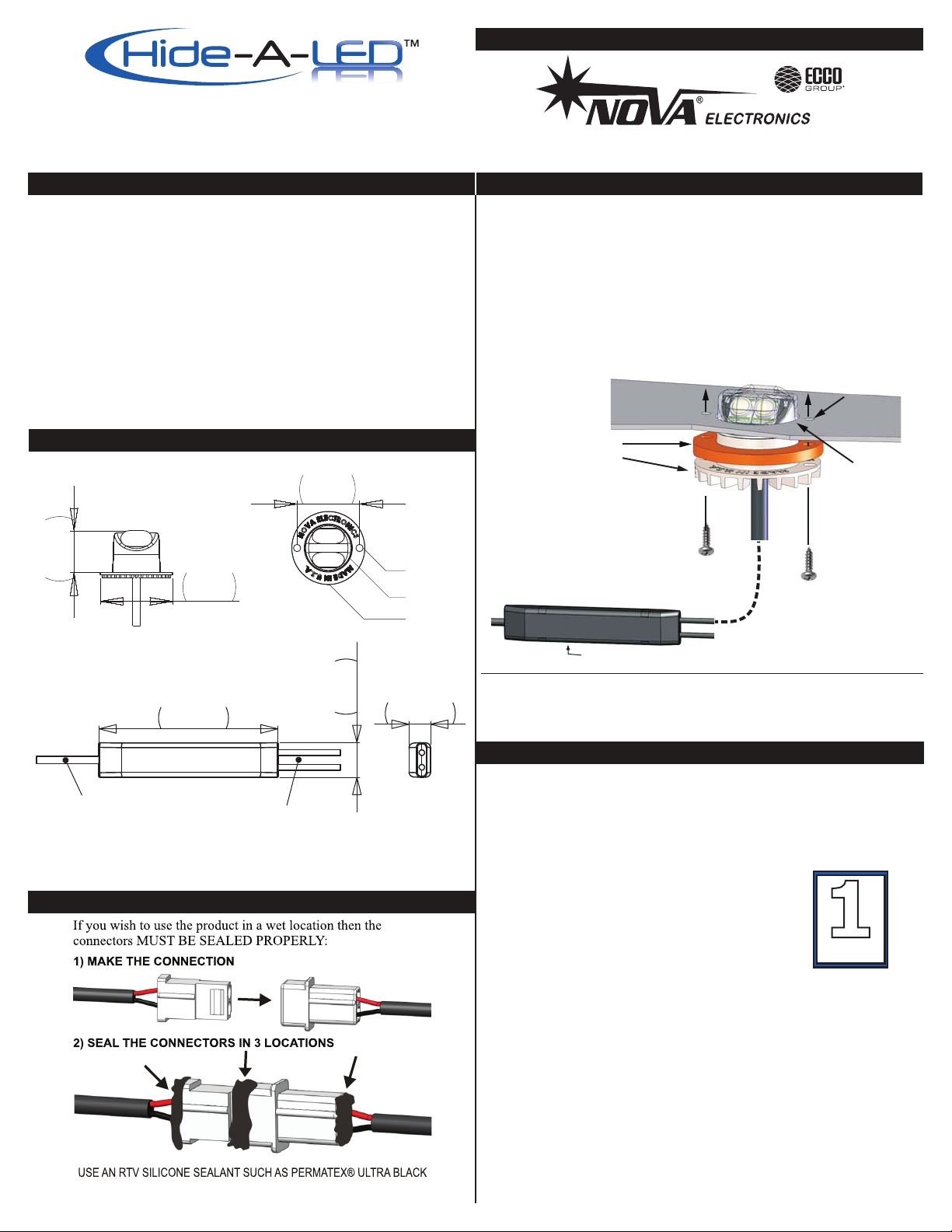
MOUNTING
Drill a 1” diameter hole in the reector of the lens assembly.
A 1” hole saw is typically used. The HIDE-A-LED™ may be used as a
template to mark the location of the two screw holes. The W600 may
be mounted in either the back surface, bottom or sides of a reector.
Drill pilot holes with a 7/64” drill bit. Install the HIDE-A-LED™ into the
lens assembly using the supplied gasket and screws. If the mounting surface is curved additional sealing may be necessary. Use RTV
Silicone sealant if needed.
LOCATE LED HEAD AT LEAST 1” AWAY
FROM ANY FACTORY BULB!
REFLECTOR
GASKET
! HOT !
THE HEATSINK WILL BE HOT AFTER RUNNING
FOR AN EXTENDED PERIOD. DO NOT TOUCH.
IT WILL NOT MELT ANY OF THE PLASTIC
PARTS OF THE LENS ASSEMBLY.
STRAP THE WATERPROOF
POWER MODULE TO THE BODY
OF THE VEHICLE AWAY FROM
ANY HIGH HEAT SOURCES.
DO NOT DRILL HOLES THROUGH THE POWER MODULE!
FOR DUAL WALL REFLECTORS: FIRST USE A 1.5” HOLE SAW TO DRILL THROUGH OUTER
LAYER ONLY. THEN USE 1” HOLE SAW TO DRILL THROUGH INNER LAYER USING SAME
PILOT DRILL HOLE. INSTALL THE LED HEAD THROUGH THE 1.5” HOLE AND SEAL THE GAP
WITH RTV SILICONE.
7/64” PILOT
HOLES
1” HOLE
SCREWS
TIP: APPLY RTV SILICONE
TO THE SCREWS TO SEAL
THE THREADS.
ELECTRICAL CONNECTIONS
The wiring diagram on page 2 shows a typical install.
INPUT MABLE: 4FT
LED HEAD
CABLES:
4FT, 7FT
POWER MODULE
CONNECTOR SEALING
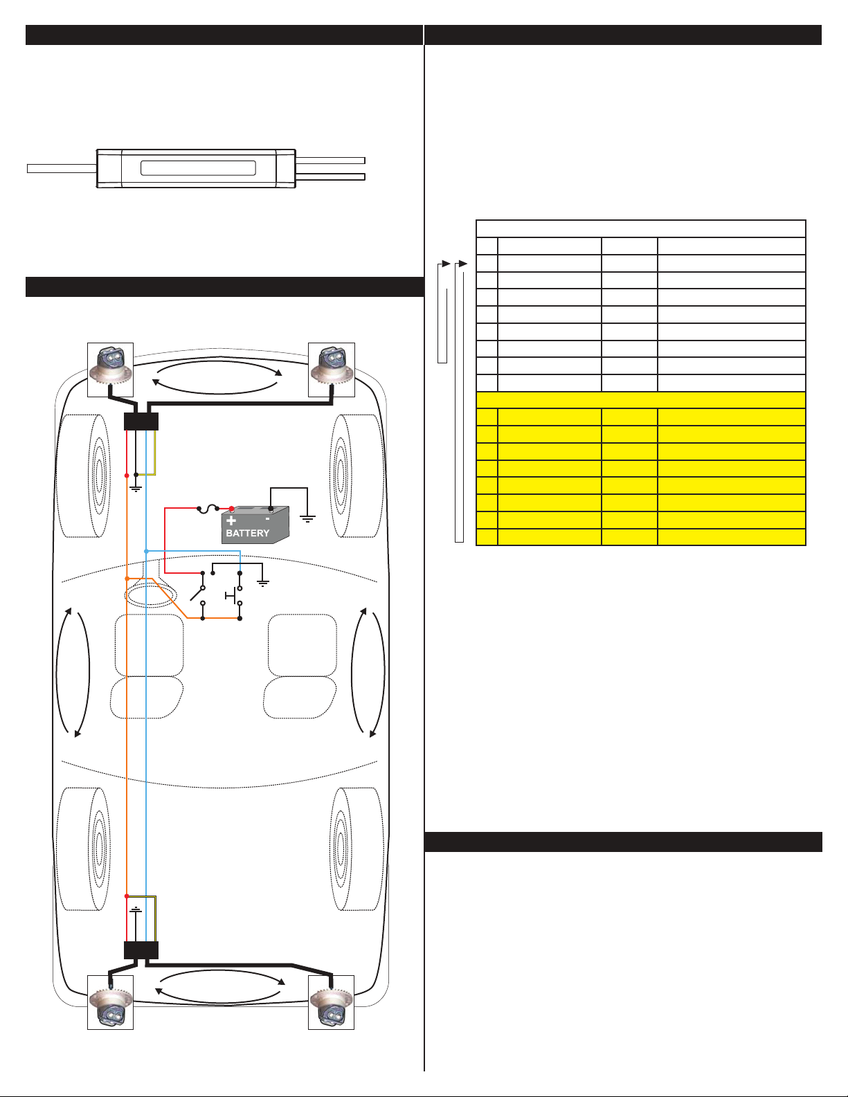
RED: +V
Connect to +V through an ON/OFF switch.
The use of a fuse located close to the voltage source is recommended.
Size the fuse according to the number of heads used in the system.
18AWG or larger wire is recommended.
BLACK: - GROUND
Connect to - GROUND vehicle chassis.
18AWG or larger wire is recommended.
BLUE: Flash pattern SYNC and SELECTION wire.
If you wish to have all the LED heads synchronize
their ash timings and patterns with each other then all the BLUE wires
must be connected together(64 Heads Maximum).
The BLUE wire is also used to select the ash pattern.
Touch the BLUE wire to +V to select the next pattern in the FLASH
PATTERN LIST. The BLUE wire can also be run to a momentary
push-button located on the dashboard to allow the ash pattern to be
changed when desired.
Note: Do not connect the BLUE wire to - Ground.
It will disrupt the ash pattern sync signal.
SYNC
TM
PAGE 1920-9121-00 REV. C
Page 2
ELECTRICAL CONNECTIONS FLASH PATTERNS
YELLOW: Swap Alternating heads.
Connect to either +V or GROUND (GND).
When using more than one HIDE-A-LED™ Deuce, this wire will swap
the order of the two LED heads so HEAD A will re with HEAD B on
the other unit. Tie to GND if not used.
HEAD A
HEAD B
POWER-UP RESET:
After installing the system it is best to do a POWER-UP RESET the
rst time to ensure that all heads are in sync.
Touch BLUE wire to +V while applying power for 1 second.
Release BLUE wire. All heads will reset to Pattern #2.
If you have installed a pattern select push-button, press and hold pattern select while turning power switch ON. Release pattern select after
1 second. To select a ash pattern, touch BLUE to +V or press pattern
select switch to increment the ash pattern. The heads will remember
the selected pattern even if power is removed.
The HIDE-A-LED™ DEUCE will also synchronize with any BULL
LED™ or SD24 LED head . The wiring colors and functions are
identical.
WIRING DIAGRAM
INSTALLATION OF 2 HIDE-A-LED™ DEUCE USING PATTERN SELECT SWITCH PANEL (OPTIONAL) ON DASHBOARD.
ALTERNATE FLASHING
KCALB
EULB
DER
WOLLEY
YELLOW TO - GND
RED
BLUE
FUSE
FFO/NO
NRETTAP
EGNARO
GNIHSALFETANRETLA
TCELES
BLACK
CHASSIS
GROUND
ANRETLA GNIHSALFET
STANDARD PATTERNS
# Pattern: Frequency: Description:
1 Quad Flash 1.25 Hz 75 Quad Flashes Per Minute
2 Double Flash 1.25 Hz 75 Double Flashes Per Minute
3 Triple Flash 1.53 Hz 92.3 Triple Flashes Per Minute
4 DeciBlast 1.42 Hz 85.5 Deci Flashes Per Minute
5 Single Flash 1.25 Hz 75 Single Flashes Per Minute
6 Mega Flash 1.90 Hz 114 Single Flashes Per Minute
STANDARD ONLY
7 Triple+Burst 1.37 Hz 82.5 Triple+Burst Flashes Per Minute
8 Steady On Steady on. Split Color = Fast Mega
CYCLE PATTERNS
9 Cycle All Cycle through patterns 1 to 7
STANDARD + CYCLE
10 Double-Triple+Burst 2 Double, 2 Triple+Burst cycle
11 Cycle Classic 1 Double, 1 Quad, 2 Mega cycle
12 Quad-Mega 3 Quad, 4 Mega cycle
13 Single-Quad 2 Single, 2 Quad cycle
14 DeciBlast-Quad 2 DeciBlast, 2 Quad cycle
15 Single-Triple-DeciBlast 2 Single, 2 Triple, 2 DeciBlast cycle
16 Mega-Triple+Burst 1 Mega, 1 Triple+Burst cycle
STANDARD PATTERNS:
In order to maintain compatibility with the BULL LED™ product, the HIDE-A-
LED™ ships with only the standard patterns enabled (1 through 8).
CYCLE PATTERNS:
You may add patterns 9 through 16 by following this procedure:
1) Touch BLUE wires to +V (RED wire) while applying power.
If you have installed a pattern select push-button, press and hold pattern select
while turning power switch ON.
2) Hold BLUE wires on +V for 5 SECONDS (heads will not be ashing during
this time). After 5 SECONDS the heads will ash once or twice to indicate the
ash pattern list that has been selected:
ONE FLASH = Standard Patterns only.
TWO FLASHES = Standard + Cycle Patterns.
3) Remove the BLUE wires from +V (or release push-button).
You may switch the pattern set at any time as many times as you wish. All
heads will remember the pattern set that was selected even when power is
removed.
© 2009
TROUBLESHOOTING
HEAD NOT FLASHING:
Check the RED and BLACK wires for a reversed connection. (Reverse connection will
not damage the unit). Check RED and BLACK wires for either a bad splice or a corroded
ground connection.
WOLLEY
KCALB
EULB
DER
YELLOW TO +V
ALTERNATE FLASHING
HEADS NOT SYNCHRONIZING:
Check for a short circuit on the BLUE wire to either +V or GROUND.
Saltwater on the wire connections will short circuit the sync signal on the BLUE wire. Check
for non-functional heads in the system. If any one of the heads has a bad GROUND connection it can cause the sync signal to become corrupted. If any one of the heads has it’s
RED and BLACK wires reverse connected it will corrupt the sync signal.
FLASH PATTERN CHANGING:
If the ash pattern changes on it’s own there may be an intermittent short between the
BLUE wire and +V. Check for water in the wiring connections. If any one of the heads in
the system has an intermittent GROUND connection it can also cause the ash pattern to
change.
PAGE 2920-9121-00 REV. C
 Loading...