

Page 1
®
4070
Tire Changer
For servicing single piece automotive and most light truck
tire/wheel assemblies.
Safety Instructions
Set-up Instructions
Operation Instructions
Maintenance Instructions
READ these instructions before placing unit in
service. KEEP these and other materials delivered
with the unit in a binder near the machine for ease
of reference by supervisors and operators.
1601 J. P. Hennessy Drive, LaVergne, TN USA 37086-3565 615/641-7533 800/688/6359 www.ammcoats.com Manual Part No.: 85608978 01
HENNESSY INDUSTRIES INC. Manufacturer of AMMCO
®
, COATS® and BADA® Automotive Service Equipment and Tools. Revision: 02/14
Page 2
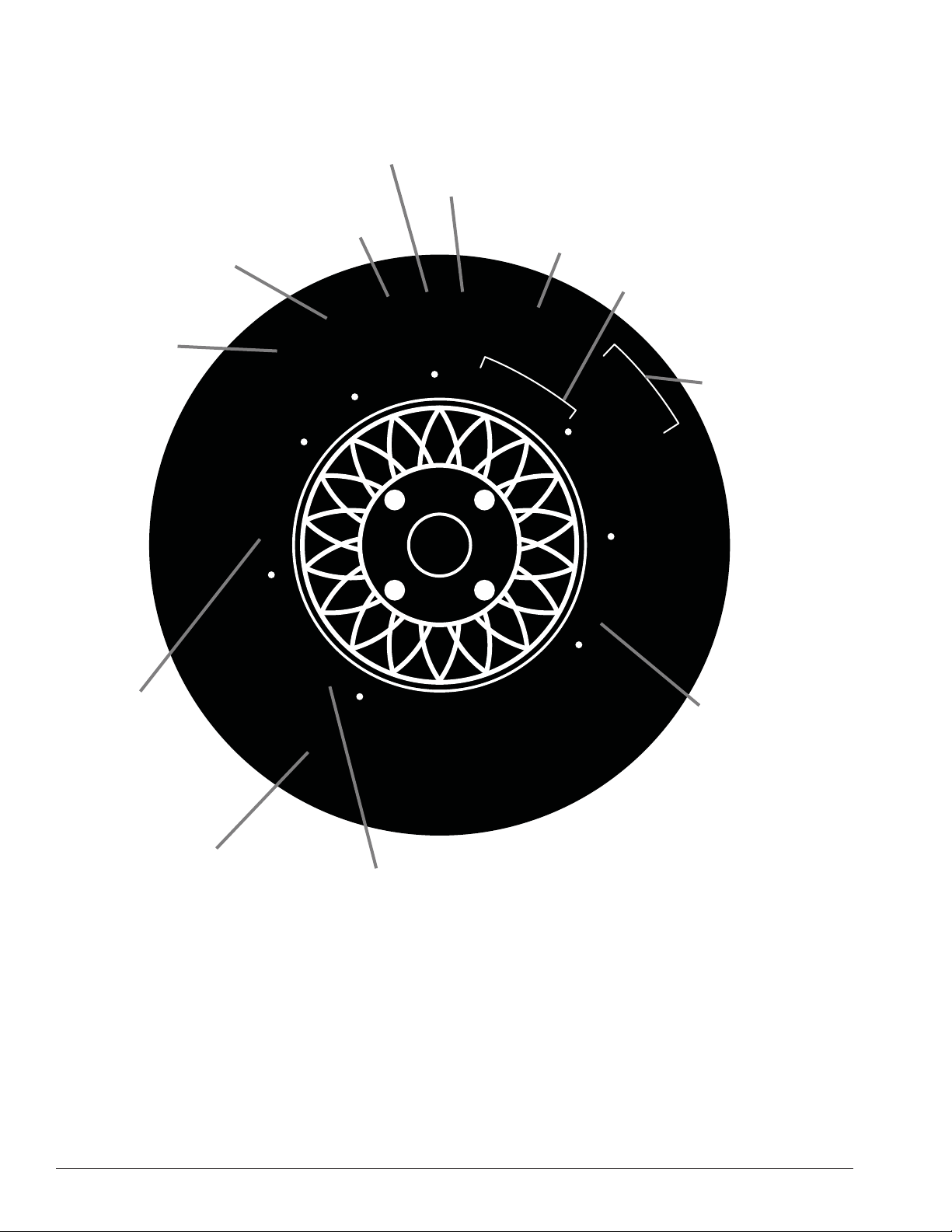
Tire Specifi cations Diagram
Nominal width of
tire in millimeters
Passenger
car tire
Max.
permissible
inflation
pressure
Radial
Ratio of height to
width (aspect ratio)
1
2
P
E
L
A
I
D
A
R
I
S
P
5
0
0
3
1
D
A
O
L
.
X
A
N
O
I
T
E
R
I
T
A
E
R
N
U
T
A
A
R
E
M
X
P
M
E
R
P
.
A
M
3
.
S
S
E
S
B
L
T
5
A
C
Rim diameter
code
Load index &
speed symbol
U.S. DOT tire
1
R
5
6
/
S
E
L
E
B
U
T
M
D
R
O
C
A
R
T
0
2
5
9
5
H
D
O
S
T
M
A
L
9
A
B
L
L
2
P
L
I
E
S
2
X
X
X
X
X
E
A
D
W
E
A
2
R
C
0
3
6
T
R
E
S
I
D
E
W
A
T
R
identification number
M
+
S
A
D
4
O
R
D
P
L
I
E
X
X
C
M
A
S
2
X
X
X
N
U
F
A
C
T
U
R
E
R
Severe snow
conditions
Tire ply
composition
and materials
used
Treadwear, traction
and temperature grades
ii • Important: Always read and follow operating instructions.
Max. load rating
Page 3
Safety Instructions
Owner’s Responsibility
To maintain machine and user safety, the responsibility
of the owner is to read and follow these instructions:
• Follow all installation instructions.
• Make sure installation conforms to all applicable
Local, State, and Federal Codes, Rules, and Regulations; such as State, Federal OSHA Regulations
and Electrical Codes.
• Carefully check the unit for correct initial function.
• Read and follow the safety instructions. Keep them
readily available for machine operators.
• Make certain all operators are properly trained,
know how to safely and correctly operate the unit,
and are properly supervised.
• Allow unit operation only with all parts in place and
operating safely.
• Carefully inspect the unit on a regular basis and
perform all maintenance as required.
• Service and maintain the unit only with authorized
or approved replacement parts.
Definitions of Hazard Levels
Identify the hazard levels used in this manual with the
following definitions and signal words:
DANGER
Watch for this symbol:
DANGER
It Means: Immediate hazards, which will result in
severe personal injury or death.
WARNING
Watch for this symbol:
WARNING
It Means: Hazards or unsafe practices, which could
result in severe personal injury or death.
CAUTION
Watch for this symbol:
CAUTION
• Keep all instructions permanently with the unit
and all decals/labels/notices on the unit clean and
visible.
• Do not override or bypass safety features.
Operator Protective Equipment
Personal protective equipment helps make tire servicing safer. However, equipment does not take the
place of safe operating practices. Always wear durable
work clothing during tire service activity. Loose fitting
clothing should be avoided. Tight fitting leather gloves
are recommended to protect operator’s hands when
handling worn tires and wheels. Sturdy leather work
shoes with steel toes and oil resistant soles should be
used by tire service personnel to help prevent injury
in typical shop activities. Eye protection is essential
during tire service activity. Safety glasses with side
shields, goggles, or face shields are acceptable. Back
belts provide support during lifting activities and are also
helpful in providing operator protection. Consideration
should also be given to the use of hearing protection if
tire service activity is performed in an enclosed area, or
if noise levels are high.
It Means: Hazards or unsafe practices, which may
result in minor personal injury or product or property
damage.
Watch for this symbol! It means BE ALERT! Your
safety, or the safety of others, is involved!
Important: Always read and follow operating instructions. • iii
Page 4
Safety Notices and Decals
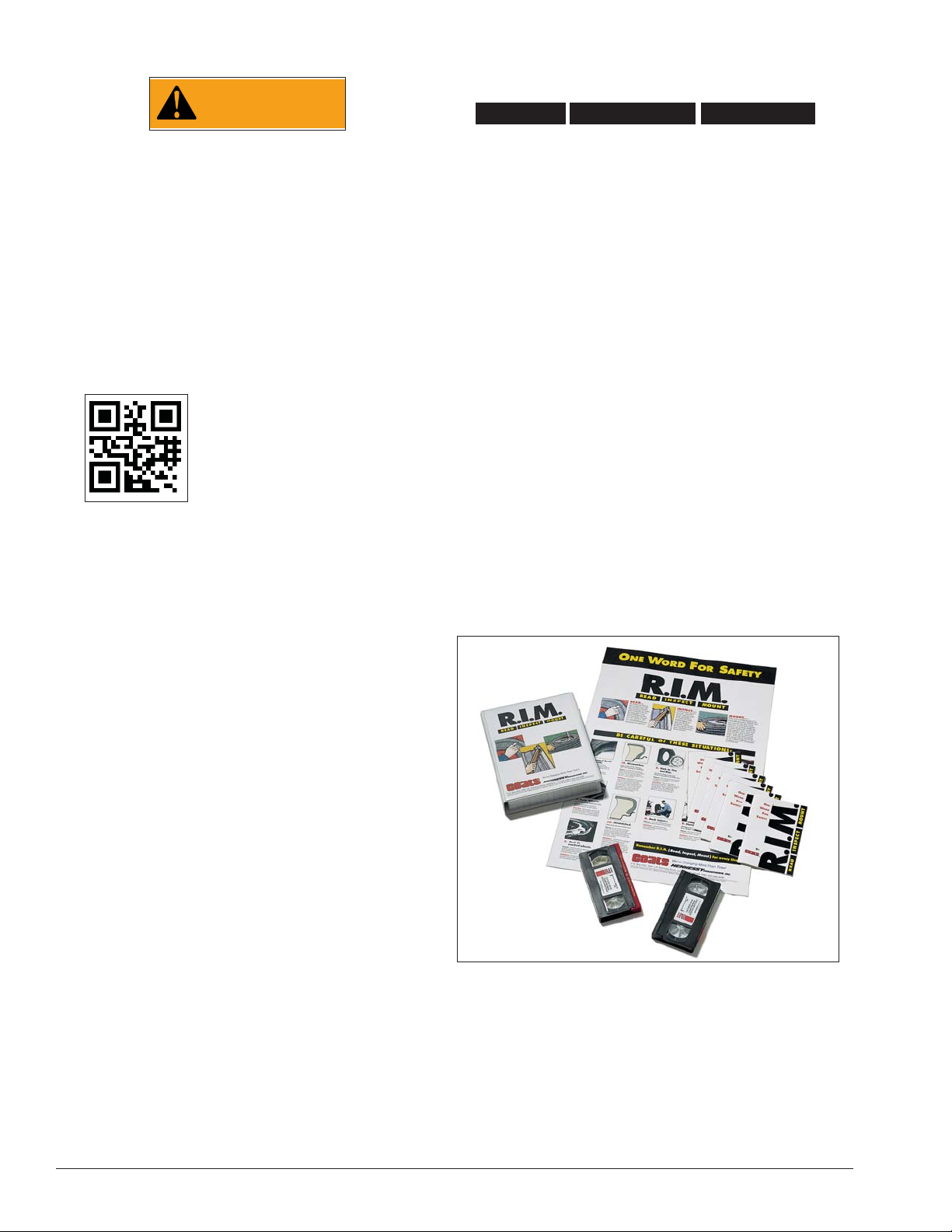
Remember R.I.M.
Three Simple Steps To Help Keep Shops Safe
WARNING
Failure to follow danger, warning, and caution
instructions may lead to serious personal
injury or death to operator or bystander or
damage to property. Do not operate this
machine until you read and understand all
the dangers, warnings and cautions in this
manual. For additional copies of either, or
further information, contact:
Hennessy Industries, Inc.
1601 JP Hennessy Drive
LaVergne, TN 37086-3565
(615) 641-7533 or (800) 688-6359
www.ammcoats.com
For additional information contact:
Rubber Manufacturers Association
1400 K Street N. W., Suite 900
Washington, DC 20005
(202) 682-4800
www.rma.org
Tire Guides, Inc.
The Tire Information Center
1101-6 South Rogers Circle
Boca Raton, FL 33487-2795
(561) 997-9229
www.tireguides.com
READ INSPECT
R.I.M. is a training program developed by Hennessy
Industries to help keep tire technicians safe. By following the basic principles of R.I.M., technicians can avoid
situations that can cause catastrophic accidents like tire
explosions.
R.I.M. stands for read, inspect, and mount:
Read the tire size on a new tire before mounting to
make sure it is the proper size for the wheel.
Inspect the wheel for cracks, rust, and or other damage that could cause an unsafe situation.
Mount the tire safely, making sure not to put any part
of your body over the tire during inflation.
The most serious of possible accidents is a tire explosion. This is often caused by a tire/rim mismatch.
If a tire explodes on a tire changer, pressure causes it
to fly straight up at tremendous speed. If a technician
is standing over the tire, he can be seriously injured or
killed.
Hennessy’s R.I.M. program allows the technician to
avoid situations that can cause tire explosions and other
accidents. The full program, including training videos,
brochures, posters, and other materials, is available
from Coats distributors nationwide.
MOUNT
For more details, contact your Coats distributor or e-mail us.
iv • Important: Always read and follow operating instructions.
Page 5

Table of Contents
Tire Specifications Diagram ..................................... ii
Safety Instructions .................................................. iii
Owner’s Responsibility ............................................iii
Operator Protective Equipment ............................... iii
Definitions of H azard Levels .................................... iii
Safety Notices and Decals ......................................iv
Remember R.I.M. ....................................................iv
Principle Operating Parts ......................................... 2
Know Your Unit ........................................................ 2
Operating Instructions ....................................... 3 -11
Tire Bead Loosening and Demounting ............... 3 - 5
Tire Mounting ..................................................... 6 - 7
Inflation..............................................................7 - 11
Stages of Inflation on a Conventional Tire
and Rim ................................................................... 12
Mismatched Tires and Wheels ............................... 13
Performance Tires/Custom Wheels ................ 14 - 15
Custom and Special Wheels .................................. 15
Tube Type Tires ........................................................ 16
Maintenance Instructions ............................... 16 - 18
Cylinder Maintenance ............................................ 16
Filling 8" Cylinders ................................................. 16
Pressure Gauge Maintenance
and Calibration ........................................................17
Lower Shoe Setting ................................................17
Routine Maintenance ............................................ 18
Setup Instructions .................................................. 18
Location ................................................................. 18
Air Source .............................................................. 18
Floor Mounting ...................................................... 18
Critical Safety Instructions ...................... Back Cover
NOTICE
Read entire manual before assembling,
installing, operating, or servicing this
equipment.
Important: Always read and follow operating instructions. • 1
Page 6
Principal Operating Parts
Do It Now!
Now is a good time to contact product service to
start warranty, otherwise warranty starts at time of
shipment.
CAUTION
Replace any damaged or missing safety
decals. They are available from COATS, (800)
688-6359.
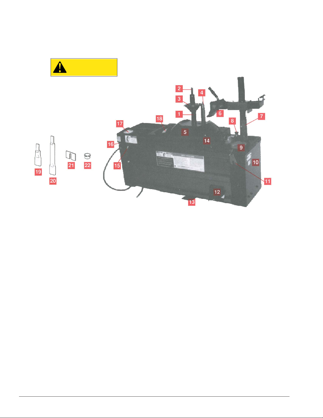
Know Your Unit
Compare this illustration with the unit before placing it
into service. Maximum performance and safety will be
obtained only when all persons using the unit are fully
trained in its parts and operation. Each user should learn
the function and location, of all controls.
Prevent accidents and injuries by ensuring the unit is
properly installed, operated and maintained.
1 Center Post
2 Center Post Key — Rotates combination tool for
mounting and demounting operations.
3 Centering Cone — Centers the wheel to the con-
toured table top.
4 Positioning Pin — Engages lug hole in wheel to
prevent rotation during mounting and demounting.
5 Contoured Table Top
6 Upper Bead Loosener Shoe — Controls operation
of bead loosener shoe.
7 Adjustable Upper Bead Loosener — Adjusts to
accommodate wide wheels.
8 Detent Control Knob — Controls the amount of
travel of the lower bead loosener to prevent damage
to large diameter narrow wheels and reverse mount
wheels.
9 Rubber Lubricant Dispenser
10 Serial Number Plate — Record the serial number
for future reference. Provide this number with any warranty or service claim, and with all parts orders.
11 Combination Tool — Used in mounting and
demounting operations.
12 Foot Pedal — Operates the air valve for power
bead loosening, mounting, and demounting.
13 Air-Flate Pedal — 3 position pedal for tire inflation
via air hose/chuck. Do not press without tire/wheel
assembly on unit.
14 Air-Flate Jets — Expands tire sidewalls to bead
seat portion of rim for the bead sealing process.
15 Air Chuck — Clip-on style.
16 Manual Release Valve — Allows for manual
release of air pressure from the tire.
17 Air Gauge — Registers tire pressure when air
chuck is attached to the valve stem and inflation pedal
is released.
18 Lower Bead Loosener — 2 shoes for lower bead
loosening.
19 Short Center Post Extension (Optional, Part
#8108313) — Lengthens center post for wheels
between 10 an 14 inches wide.
20 Long Center Post Extension (Optional, Part
#8108313) — Lengthens center post for wheels over
14 inches wide.
21 1/4” Shim — Installs on lower bead loosener to
prevent damaging aluminum and magnesium wheels
with wide flanges.
22 Hold Down Tube — Used with styled steel wheels
to prevent the centering cone from touching the wheel
2 • Important: Always read and follow operating instructions.
Page 7
Operating Instructions
The unit must be properly operated and properly
maintained to help avoid accidents that could damage
the unit and injure the operator or bystanders. This
section of the Operating Instructions manual review
basic operations and use of controls. These instructions
should be reviewed with all employees before they are
allowed to work with the machine. Keep these instructions near the machine for easy reference.
Tire Bead Loosening and Demounting
CAUTION
This machine may operate differently from
machines you have previously operated.
Practice with a regular steel wheel and tire
combination to familiarize yourself with the
machine’s operation and function.
NOTE: Always review nicks and scratches with own-
ers of expensive wheel and tire combinations prior to
servicing.
IMPORTANT: Refer to the Performance Wheels and
Tires section of this manual before servicing custom
and performance wheel and tire combinations.
3. Place the tire/wheel assembly over the center post
and down onto the contoured table top, with the narrow
side of bead seat up (figure 1)The positioning pin must
engage a lug hole in the wheel. Position the tire/wheel
assembly so that the valve stem is on the operator’s
side of the machine.
NOTE: Make fine adjustments to the lower bead
loosener shoe with the shim kit before placing mag or
alloy wheel assemblies on the table top. Refer to the
instructions on bead loosener shoe.
4. Thread centering cone clockwise onto the center
post. As the tapered end enters the center hole of the
wheel, the tire/wheel assembly will adjust itself on the
table top. Be sure the cone is hand tight and is centered
in the wheel’s center hole (Fig. 2).
IMPORTANT: Refer to the Tube Type Tires section of
this manual before servicing tires with tubes.
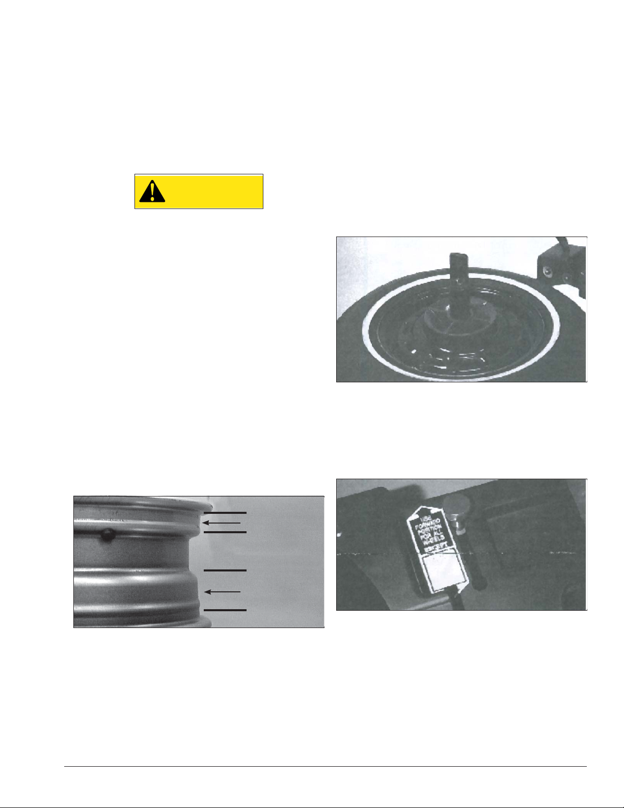
1. Determine the correct side of the wheel for tire
removal. Remove the tire from the narrow side (tire
mounting side). Tire will not mount or demount from
the long side.
NOTE: On some wheels, the sides may be nearly
equal. Measure carefully. Only the narrow side is used
for mounting and demounting.
Narrow Side
Drop Center
Long Side
Figure 1 - Determining Tire Mounting Side
2. Remove the valve core and allow all of the air to
escape from the tire. Remove all weights from rim.
Figure 2 - Thread the Centering Cone onto the Center Post
5. Check the detent control knob for proper setting.
Forward is used for all tire and wheel combinations
except 15” x 4” , 16” x 5” to 7” , and 17.5” x 5.5” to 7.5”.
To move the detent lever, push the knob down, move it
to the proper setting, and release the knob (fig. 3).
Figure 3 - Positioning the Detent Control Knob
.
Important: Always read and follow operating instructions. • 3
Page 8
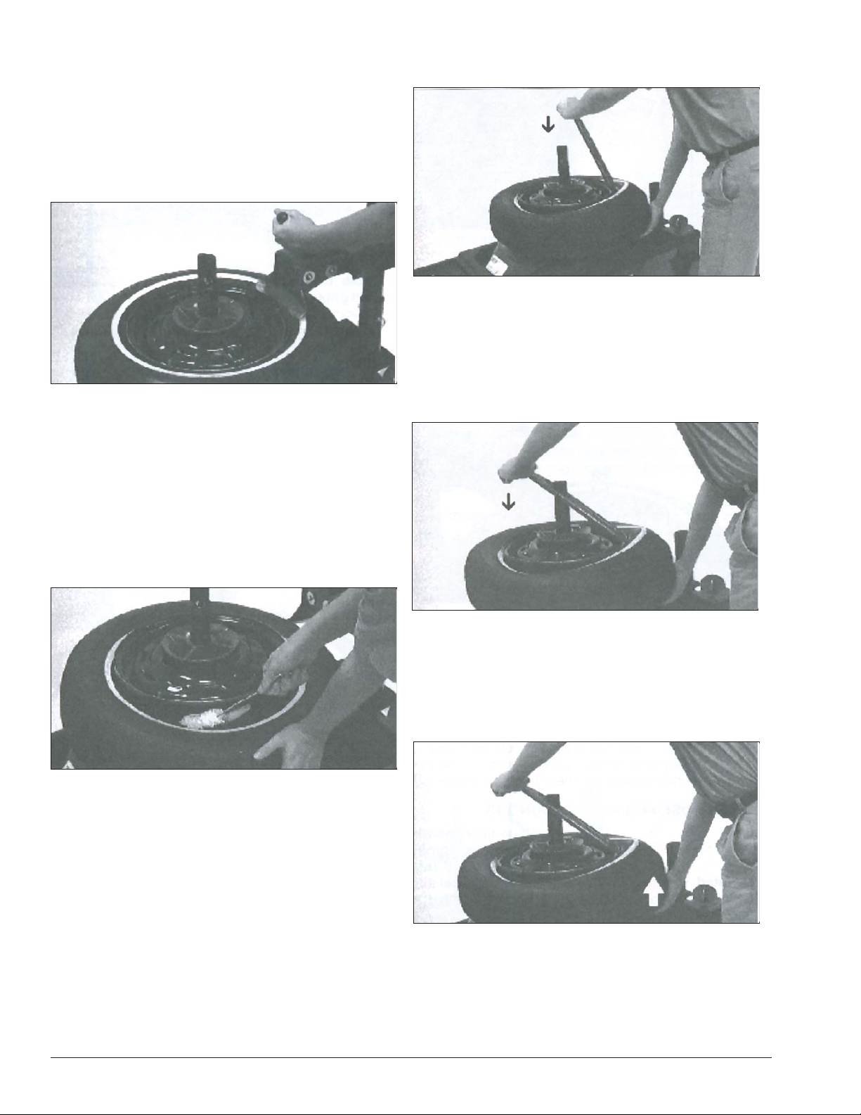
6. Place the upper bead loosener shoe on the tire
next to, but not on, the rim (fig. 4). Press down on the
foot pedal until both bead looseners complete their
full stroke. If the top bead is not completely loosened,
release the foot pedal until the unit has completed the
full return stroke and press the foot pedal again. The
ratchet effect on the loosener will deliver a deeper
stroke. The repeat cycle is used only if the upper bead
is not loosened.
Figure 4 - Positioning the Upper Bead Loosener Shoe
Note: If may be necessary to loosen the bead at differ-
ent points around the wheel circumference to entirely
free the bead.
IMPORTANT: Make sure the tool is oriented as shown
in figure 6.
Figure 6 - Align, Insert, and Push Down on the Tool
9. Continue to push down on the tool until the center
post key protrudes through the slot in the tool and the
tool stops against the shoulder of the key. The tool is
now positioned properly for operation of the center post
key (figure 7). Keep a firm hold on the tool at all times to
prevent accidental disconnect.
7. Once the tire beads have been loosened from the
bead seat of the wheel, lubricate the beads liberally
with rubber lubricant (fig. 5).
Note: Rubber lubricant makes demounting easier,
helps eliminate damage to the tire beads, and assists
the movement of the combination tool.
Figure 5 - Lubricate Tire Beads
8. Position the combination tool so that it aligns with
the center post key. Insert the demount end of the tool
between the tire and rim. Push the tool down towards
the center post as shown in figure 6 to lift the tire bead
over the rim.
Figure 7 - Tool Properly Positioned
10. Press down on the foot pedal. The counterclock-
wise rotation of the center post key and combination
tool will remove the upper tire bead from the rim. Lifting
up on the tire with the left hand as shown by the arrow
in figure 8 helps in demounting tougher tires.
Figure 8 - Removing Upper Bead
11. To remove the lower bead from the wheel, repeat
steps 8, 9, and 10.
4 • Important: Always read and follow operating instructions.
Page 9

REMEMBER: Refer to the Tube Type Tire section of
this manual before servicing tires with tubes.
DANGER
Fast or jerky movement of the bead loosener
shoes or the combination tool indicates low
cylinder oil level, and may result in throwing
or disengaging of the tool, possibly causing serious injury or death to operator or
bystander. Do not operate until it has been
returned to proper operating condition. See
the Maintenance section of this manual for
further instructions on maintenance and
adjustment.
When the demount operation is complete, proceed
with Mounting, page 6.
Important: Always read and follow operating instructions. • 5
Page 10

Tire Mounting
This information must be read and followed carefully
to prevent accidents and injuries during mounting.
WARNING
Check tire and wheel carefully before
mounting. Make sure the tire bead diameter
and wheel diameter match exactly. Consult the Rubber Manufacturer’s Association
for approved rim widths for tire sizes. Mismatched tires and wheels explode.
CAUTION
Never Mount a tire and wheel handed to
you by anyone without checking both tire
and wheel for damage and compatibility. Be
extra cautious of persons without knowledge of tire service. Keep by-standers out of
service area.
Figure 9 - Inspect Wheel Before Beginning
WARNING
Never mount a damaged tire. Never mount a
tire on a rusty or damaged wheel. Damaged
tires and/or wheels may explode.
CAUTION
If you damage the tire bead during mounting, STOP!, remove the tire and mark it as
damaged. Do not mount a damaged tire.
1. Inspect the wheel closely for damage. Remove
any rubber or light corrosion from rim (figure 9). Inspect
both the inside and outside of the tire, and pay special
attention to the bead area. Do not attempt to service
heavily corroded wheels. Apply rubber lubricant to the
outside of both beads and to the inside of the top bead
(figure 10).
2. Place the tire over the wheel as shown in figure 11.
Hook the mounting end of the combination tool over the
rim flange and place the slot in the tool over the center
post key.
Figure 10 - Lubricate Beads
Figure 11 - Positioning Tire and Combination Tool
4. Push down on the tire with your left hand to hold
the lower bead in the drop center of the wheel. Use
your right hand to hold the combination tool down over
the center post key. Refer to figure 11.
5. Press the foot pedal. Continue to push the tire down
into the drop center and maintain pressure against the
combination tool while it rotates. Allow the combination
tool to make a full cycle.
3. Grasp the tire and rotate it clockwise until the
lower bead contacts the mounting end of the tool.
Continue to rotate the tire until the bead slides into the
groove on the tool (figure 11).
6 • Important: Always read and follow operating instructions.
Page 11

6. Mount the upper bead in the same manner (figure
12). Repeat steps 2, 3, 4, and 5.
Figure 12 - Mounting Upper Bead
WARNING
Do not force the tire onto the rim. Bead damage could result making the tire unsafe and/
or creating the risk of injury in mounting
operations.
When you have completed the mounting process,
proceed to Inflation, page 8.
Important: Always read and follow operating instructions. • 7
Page 12

Inflation
Tire inflation is performed in three steps: Bead Seal,
Bead Seat and Inflation. These steps are explained in
detail on page 12. Read the explanation of each step
and understand them thoroughly before proceeding.
CAUTION
Check for proper inflation gauge operation.
Accurate pressure readings are important
to safe tire inflation. Refer to the Operating Maintenance section of this manual for
instructions.
DANGER
Tire failure under pressure is hazardous. This
tire changer is not intended to be a safety
device to contain exploding tires, tubes,
wheels, or bead sealing equipment. Inspect
tire and wheel carefully for match, wear,
or defects before mounting. Always use
approved tire bead lubricant during mounting and inflation.
Figure 13 - Air-Flate Pedal Positions
The COATS Air-Flate system is operated with a three
position foot pedal (referred to as the Air-Flate pedal).
Each position of the Air-Flate pedal performs a specific
function (figure 13):
Position 1 - Tire Pressure – When foot is removed
from the pedal, it will return to this position. When the
inflation hose is attached to the tire valve, the pressure
gauge will register the pressure in the tire.
NOTE: The clip-on chuck on the end of the hose is an
important safety aid and should always be an open style
with all parts in proper working order.
Position 2 - Tire Inflation – By pressing the Air-Flate
pedal down to this first activated position, full air line air
pressure is applied to the inflation hose for tire inflation.
Remove your foot from the pedal (position 1) to read
tire pressure on the pressure gauge. See page 7 for
pressure limiter information.
Position 3 - Bead Sealing – Press the pedal down
fully and full air line air pressure is applied to the inflation hose and to the bead seal jets mounted in the top
cover.
CAUTION
Use Position 3 for bead sealing only. Do not
use this position without a tire and wheel
positioned on the tabletop. Dirt and debris
could be blown into the air with enough
force to injure the operator or bystanders.
Do not use the position to inflate a tire.
8 • Important: Always read and follow operating instructions.
Page 13

Bead Sealing
1. Connect the inflation hose to the tire valve stem.
Bead Seating
2. Lift tire so that the upper bead is against the edge
of the rim to create a seal. Be sure the upper bead is
over the bottom of the valve stem (figure 14).
Figure 14 - Bead Sealing
3. Depress the Air-Flate pedal to position 2 and hold
for 1 second to begin air flow through the inflation hose,
then depress the Air-Flate pedal fully to position 3, hold
very briefly (less than 1 full second), and remove foot
from the pedal. The blast of air through the inflation
hose and the top cover jets will expand the tire and seal
the beads (figure 14).
4. Check to make sure that the beads are sealed to
the wheel. Repeat step 3 if they are not fully sealed.
NOTE: Allow time for the surge tank pressure to
recover before depressing the pedal to position 3 again.
TIP: If the tire and wheel are properly lubricated and
the operator cannot achieve bead seal after 3 attempts,
it may help to remove the valve core. Remove the air
chuck from the valve stem and unscrew the valve core
from the stem. Reattach the air chuck and perform the
bead seal operation again.
5. Check tire pressure (Air-Flate pedal must be in
position 1). If pressure is indicated in tire, bead seal has
been obtained. Proceed to Bead Seating.
WARNING
Operator should keep hands, arms, and
entire body away from the tire and wheel
during the remaining Bead Seat and Inflation procedures. Do not stand over tire, as
personal injury could result.
WARNING
NEVER increase air pressure to exceed 40
PSI when attempting Bead Seat. If unable
to obtain Bead Seat, something is wrong.
Deflate tire completely, inspect both the tire
and wheel, and correct any problems found.
Relubricate both tire beads, and reattempt
Bead Seal and Bead Seat procedures. Follow
all safety instructions in this manual and on
machine.
WARNING
Do not force the tire onto the rim. Bead damage could result making the tire unsafe and/
or creating the risk of injury.
Check tire pressure frequently. Never exceed 40 PSI
while seating beads. Once seated, never exceed tire
manufacturer’s recommended air pressure. Tires can
explode, especially if they are inflated beyond their
limits. At all pressure levels when inflating through the
valve stem, keep hands, arms, and entire body away
from inflating tire. An exploding tire, wheel, or bead
sealing equipment may propel upward and outward
with sufficient force to cause serious injury or death to
operator or bystander.
1. Verify that beads are sealed by checking the gauge
for air pressure in the tire. Do not proceed if beads are
not sealed.
2. If beads are sealed, loosen the centering cone one
full turn. DO NOT REMOVE IT!
Important: Always read and follow operating instructions. • 9
Page 14

3. Inject frequent, short bursts of air into the tire by
pressing the Air-Flate pedal to position 2 and releasing.
Continue the bursts until the beads move outward into
their bead seat position.
Check the pressure frequently. If beads do not seat,
a problem exists. Investigate carefully and correct the
problem.
Figure 15 - Stand Back During Beat Seat and Inflation
4. Proceed to the inflation step only when both beads
are completely and properly seated.
Inflation
DANGER
NEVER exceed tire manufacturer‘s recommended air pressure. Tires can explode,
especially if inflated beyond these limits.
Keep hands, arms, and entire body back
from inflating tire. Avoid distraction during
inflation and observe tire pressure frequently
to avoid over inflation. Excessive pressure
can cause tires to explode, causing serious
injury or death to operator or bystander.
REMEMBER: If you removed the valve core for bead
sealing, it must be reinstalled before the tire is inflated.
1. Depress the Air-Flate pedal to position 2 and inflate
the tire. Release the pedal to position 1 and check the
increasing pressure frequently to avoid over inflation.
IMPORTANT: The 4070 is equipped with a pressure
limiter to assist the operator with proper tire inflation.
The 4070 limiter will keep most car and light truck tires
from inflating beyond 60 PSI (smaller tires may reach
higher pressures). Tires that require inflation above 60
PSI should be removed from the 4070 and inflated
using a safety chamber or safety cage. Tires can be over
inflated and explode even with the use of this pressure
limiter if other instructions in this manual and on the
unit are not followed. Check the function of the pressure limiter regularly and maintain as required for safe
and proper operation.
IMPORTANT INFLATION FEATURE: If the Air-Flate
pedal is held steady at position 2, the Air-Flate system’s
pressure limiter will automatically cycle between inflation and off. This cycle will continue until the pedal is
released. The operator should check the increasing
pressure frequently to avoid over inflation.
Figure 16 - Release Pressure with the Manual Release Valve
10 • Important: Always read and follow operating instructions.
Page 15

DANGER
DANGER
Explosion Hazard
Never exceed 40 PSI while
seating beads. If you use
more than 40 PSI always
use safety cage.
Remember R.I.M.
(see page iv and back cover)
Explosion Hazard
Never infl ate tire
above
manufacturer’s
recommended
pressure after
bead is seated.
Important: Always read and follow operating instructions. • 11
Page 16

Stages of Infl ation on a
Conventional Tire and Rim
Review these descriptions and diagrams carefully. Refer to them as
necessary during bead sealing, bead seating, and inflation to verify that
you are proceeding properly and safely.
Bead Sealing
Bead sealing is the process of capturing air pressure between the
tire and the rim. The tire will usually contain about 1/2 to 2 PSI at initial
bead seal.
Bead Seating
Bead seating usually occurs on the long tapered side of the wheel
first and the shorter side last. Bead seating will usually require at least
7 PSI in the tire. 40 PSI is the maximum safe pressure at this stage
regardless of tire operating pressure. For tires requiring more than 40
PSI to bead seat use safety cage.
Most European import cars and many aftermarket alloy wheels are
very tight and can be difficult to bead seat. Also note that asymmetrical
hump and run-flat tires are extremely difficult to bead seat. Follow tire
manufacturer’s recommended procedure for bead seating.
Inflation
After the beads are seated, the tire is ready to be inflated. Do not
inflate the tire above the manufacturer’s recommended pressure as
stamped on the tire sidewall. The typical inflation pressure for automobile tires is between 24 and 45 PSI. Light truck inflation pressure
typically covers a wider range.
12 • Important: Always read and follow operating instructions.
Page 17

Mismatched Tires and Wheels
Never mount and inflate mis-matched tires and
wheels.
DANGER
Mismatched tire and wheel combinations will explode,
if you attempt to force a bead seat, causing personal
injury or death to operator and/or bystanders.
Important: Always read and follow operating instructions. • 13
Page 18

Performance Tires/Custom Wheels
Before You Begin - Pre-Operation Notes
Only tire technicians with training on custom wheels
should attempt to service expensive custom alloy or
aluminum wheels and high performance low-profile
tires.
• Ensure all weights have been removed from the
wheel before servicing.
• Assistance will be required on wide wheels.
• Use ample lubricant during mounting and demounting operations.
• Always review wheel nicks and/or scratches with the
owner before servicing.
3. For mounting and demounting tires on wheels
from 10” to 14” wide, use the optional short center
post extension (part #8108311). Slip the extension over
the center post key (figure 19).
1. Check the clearance on the lower bead loosener
shoe. If it does not clear the rim lip,install the 1/4” shim
(figure 17).
To Install the Shim: Remove the tire/wheel assembly
from the tabletop and depress the foot pedal. The
loosener shoe will extend to the top of it’s stroke. Do
not release the pedal. Tilt the bead loosener shoe away
from the center post and slip the red 1/4” thick shim
over the end of the bolt between the shoe adjusting bar
and the lower shoe.
Figure 17- Installing 1/4” Shim
Figure 19- Optional Short Center Post Extension
4. For mounting and demounting tires on wheels
wider than 14” , use the optional center post extension
(part #8108313). Slip the extension over the center post
key (figure 20).
Figure 20 - Optional Long Center Post Extension
5. On wheels with thin or delicate center holes that
may be damaged by the centering cone,use the optional
Speed Mag or Custom Wheeler Adapter (figure 21).
2. To service wheels over 11” wide, extend the upper
bead loosener post. Remove the clevis pin, raise the
post to the appropriate height,and reinsert the pin
(figure 18).
Figure 21 - Optional Speed Mag Adapter
Figure 18- Extending Upper Bead Loosener Post
14 • Important: Always read and follow operating instructions.
Page 19

6. Use the plastic combination tool boots supplied
with the optional Speed Mag adapter to prevent scratching of custom wheels (figure 22). Boots may be ordered
separately (part#8106568, 10 pairs).
Figure 22 - Combination Tool Boot
Custom and Special Wheels
CAUTION
Only tire technicians with experience and
training on custom wheels should attempt
to service expensive custom alloy or aluminum wheels and high-performance lowprofile tires.
Alloy Wheels
Some manufacturers offer wheels with little or no drop
center. These are not DOT approved. The tire or wheel
- or both - can be damaged and the tire could explode
under pressure , resulting in serious injury or death. Do
not mount/demount this type of wheel (figure 23).
No
Drop
Center
Figure 23 - No Drop Center
European Performance Wheels
(Asymmetrical Hump)
Some European wheels have very large humps except
near the valve hole. On these wheels, the beads should
be loosened at the valve hole on both the upper and
lower sides first (figure 24).
Valve Hole
Slight
Hump
Figure 24 - Asymmetrical Hump on European Wheels
Large
Hump
Wheels with Low Pressure Warning Sensors
Performance wheels on some vehicles (including
Corvette, BMW, Lamborghini Diablo) have a pressure
sensor strapped to the rim opposite the valve hole. On
these wheels, the beads should be loosened at the
valve hole on both upper and lower sides first (figure
25).
Transmitter
Valve Hole
Mounting
Strap
Figure 25 - Wheels with Low Pressure Sensor
Important: Always read and follow operating instructions. • 15
Page 20

Tube Type Tires
Maintenance Instructions
Mounting
1. Avoid pinching or forcing the tube.
2. Apply rubber lubricant to the beads of the tire.
3. Mount the bottom bead.
4. Round out the tube with a small amount of air.
5. Apply rubber lubricant to the tube.
6. Insert the tube into the tire.
7. Mount the top bead.
Demounting
1. After tire beads are loosened, lubricate the beads
and rim liberally.
2. Position demount tool and bead lifting tool as
described in steps 8 through 12 on pages 4 and 5.
Depress table top pedal and rotate only a short distance
at a time. This allows you to stop the process should the
tube get pinched.
3. After upper bead is demounted, remove tube and
demount lower bead.
Do It Now
Make sure the instruction and warning decal
✔
is clean and clearly visible to operator.
Read and follow all the maintenance instructions provided in this manual to keep the machine in good operating condition. Refer to the other materials received
with the unit and to the service bulletins from the
manufacturer for additional instructions on proper maintenance and service. Regular inspections and proper
maintenance are essential to preventing accidents and
injuries.
WARNING
Before making any inspection, adjustment,
or repair, disconnect the power source and
block out all moving parts to prevent injury.
WARNING
Keep the machine and the immediate work
area clean. Do not use compressed air to
remove dirt and debris from the machine.
Foreign material may be propelled into the
air and into operator or bystander causing
personal injury.
WARNING
Wear protective clothing, equipment and
eye protection when making any adjustments or repairs to the machine.
Cylinder Maintenance
The unique design of the hydraulically dampened
8” cylinder controls bead loosening, mounting, and
demounting. If the oil becomes low, the machine will
surge at the beginning of its stroke. A special hydraulic
oil must be used.
Filling 8” Cylinders
Fill only with COATS Hydraulic Oil (part #8101411) or an
approved alternate choice (Empak 4061, or Shell Tellus
21). Do not use motor oil or brake fluid.
1. Remove cylinder (part #85608715) and slave cylin-
der (part# 85608739).
2. Remove plug from slave cylinder and fill with oil
until there is no air in either cylinder or connecting hose.
16 • Important: Always read and follow operating instructions.
Page 21

Pressure Gauge Maintenance and Calibration
Check the tire pressure gauge function on the unit
daily, and perform an accuracy check monthly. Use a
pressurized tire and a high quality stick pressure gauge.
If necessary, calibrate the dial of the machine gauge.
1. Pressurize a large 15” tire to 30 PSI and measure
the pressure exactly with a high quality extension type
tire gauge. Connect the air chuck to the tire.
2. Remove the gauge lens and loosen the 2 screws at
the top of the gauge and rotate the gauge face until the
indicator is pointed at the correct pressure as read with
the extension type tire gauge (figure 26).
3. Tighten gauge face screws and replace lens.
If gauge is defective, replace it immediately (part
#8107985).
Check the function of the pressure limiter weekly as
part of your pressure gauge maintenance and calibration.
Lower Shoe Setting
Check the lower shoe setting periodically to make
sure that it operates properly and does not contact the
wheels.
1. Place a 15” or 16” steel wheel on the machine and
secure with the centering cone.
NOTE: Make sure the wheel is centered.
2. Depress the foot pedal and run the lower shoe up
to 45 degrees above the radius of the lower rim flange.
Refer to figure 29.
Figure 26 - Calibrating Pressure Gauge
3. Use your left hand to push against the shoe as
forcefully as possible.
4. Measure the gap between the closest point of
the shoe and the rim flange. The ideal measurement is
between 1/16” and 1/8” .
• If the shoe contacts the rim, add another shim.
• If the gap is smaller than 1/16” , add another shim.
• If the gap is larger than 1/8” , remove one shim.
IMPORTANT: A high setting (greater than 1/8”) is
more desirable than a low setting (less than 1/16”).
If additional shims are required, a Shim Kit (part
#8101506) is available.
Important: Always read and follow operating instructions. • 17
Page 22

Routine Maintenance
A. Keep work surface clean. Pay special attention to
the top of the machine.
B. Clean and wipe down the machine on a regular
basis.
C. Clean the gauge lens frequently with glass cleaner.
D. Make sure all fasteners are tightened securely.
E. Make certain that all guards and covers are in place.
Setup Instructions
CAUTION
Proper unit installation is necessary for safe
use and efficient operation. Proper installation also helps protect the unit from damage and makes service easier. Always place
safety poster and instructions near the unit.
F. Check for worn, damaged, or missing parts (includ-
ing grips, warnings, instructions, and protective covers).
Replace before allowing unit to be used.
G. Inspect the unit on a daily basis. Check that all
systems and functions are operating normally. Detailed
inspection and testing procedures are specified for various components at regular intervals. Set up a chart and
assign responsibility for these items.
CAUTION
These instructions will help you service the
unit. Instructions are for a person with some
mechanical ability and training. No attempt
has been made to describe all basic steps.
For example, how to loosen or tighten fasteners. Also, basic procedures such as how
to cycle systems and check operation of the
equipment are not fully described since they
are known to anyone who does mechanical
and service work. Do not attempt to perform
work beyond your ability, or at which you
have no experience.
If you need assistance or technical support, contact
an authorized COATS Service Center, or The COATS
Company Service Department at (800) 688- 6359.
Location
Select a location using the drawings below. The area
should provide the operator with enough space to use
the equipment in a safe manner. The area selected
should be well lit, easy to clean and should be away
from oil, grease, brake lathe chips, etc. Avoid areas
where bystanders and customers may be present.
Workspace Requirements
Air Source
The unit requires a 5 CFM air source at 150 PSI. The
operating pressure range for all models is between 110
PSI and 175 PSI at the machine.
The unit is furnished with a 1/4" pipe thread male fitting for easy connection. This connection is located on
the right side of the rear of the machine. A 1/4" ID hose
(or pipe) for connection to the machine is satisfactory.
Sufficient air pressure ensures good performance.
Floor Mounting
As Hennessy can not be certain of the environment
and conditions of the locations where the equipment
will be installed, it is recommended that the safety
manager review the shop floor conditions and local
regulatory practices to determine if bolting of the equipment to the shop floor is necessary or advisable.
18 • Important: Always read and follow operating instructions.
Page 23

Important: Always read and follow operating instructions. • 19
Page 24

ONE WORD FOR SAFETY
R.I.M.
READ INSPECT MOUNT
READ…
Mounting and inflating the
wrong size tire can get
you hurt. Read the size on
the tire and make sure it
matches the rim. Be especially careful about putting
a smaller tire on a larger
rim, such as a 16-inch tire
on a 16.5-inch rim.
Inflation of a mismatched
tire and rim can cause an
explosion.
BE CAREFUL OF THESE SITUATIONS:
1. Damaged Bead or
Beads.
2. Rusty Wheels.
(particularly in the
bead seat area)
3. Bent or Cracked
Wheels.
4 A. Mismatched.
(A mis-match of a
16-inch tire to a 16.5inch rim causing an
explosion)
4 B. Mismatched.
(16.5-inch tire on a
16-inch rim)
INSPECT…
Before you put any tire
on a rim, inspect the rim
for rust, tough spots, bent
edges, or cracks that could
prevent the tire from seating right. If you spot any
of these problems, don’t
mount the tire until the rim
has been checked by your
shop foreman.
Inspect the tire for bead
damage.
5. Walk-In Tire and
Rim.
6. Back Injuries.
7. Hand or Finger
Injuries.
(Hands or fingers too
close to inflating tire
or bead seats which
may cause injury.)
MOUNT…
Once you’ve made sure the tire is OK
and the right size and the rim is OK,
mount the tire safely. NEVER, ever lean
over the tire when you’re inflating it. If
a tire does explode, it will go straight
up. You don’t want to be over the tire
if that happens. Also, never over-inflate
the tire, even if the bead doesn’t seat.
Never inflate over 40 PSI. If the tire
hasn’t seated, something is wrong.
Deflate the tire and check it and the
rim again. If it doesn’t work the second
time, try another tire.
8. Standing Clear.
(Never put any part
of your body over the
tire changer during
inflation.)
9. Beads will not
Seat at 40 PSI.
10. Improper
Inflation.
Remember R.I.M. (Read, Inspect, Mount) for every tire.
TIRE FAILURE UNDER PRESSURE IS HAZ-
FAILURE TO READ AND FOLLOW ALL WARNINGS AND INSTRUCTIONS IN THIS MANUAL
CAN LEAD TO SERIOUS PERSONAL INJURY
OR DEATH TO OPERATOR OR BYSTANDER.
THE OWNER IS RESPONSIBLE FOR MAINTAINING THE OPERATION INSTRUCTIONS
AND DECALS FOR OPERATOR REFERENCE.
FOR ADDITIONAL COPIES, CONTACT THE
COATS® COMPANY, 1601 J.P. HENNESSY
DRIVE, LAVERGNE, TENNESSEE, 37086 - (800)
688-6359.
85608978 01 02/2014 © Copyright 1993, 2001 Hennessy Industries and COATS® All Rights Reserved. Printed in USA
DANGER
ARDOUS! This tire changer Will Not Restrain
Exploding Tires, rims or other related equipment.
TIRES CAN EXPLODE, ESPECIALLY IF
INFLATED BEYOND SPECIFIED LIMITS. DO
NOT EXCEED TIRE MANUFACTURERS RECOMMENDED AIR PRESSURE.
AN EXPLODING TIRE, RIM, OR BEAD SEATING EQUIPMENT MAY PROPEL UPWARD
AND OUTWARD WITH SUFFICIENT ENERGY
TO CAUSE SERIOUS INJURY OR DEATH TO
OPERATOR AND/OR BYSTANDERS.
 Loading...