

Page 1
8113936 00 10/04 page 1 of 4
16 Bit PCB & Metal Arm Temporary
Instructions - 1800/1850 Balancer
COATS, Inc. • Hennessy Industries • 1601 J.P. Hennessy Drive, LaVergne, TN 37086-3565
(800) 688-6359 • (615) 641-7533 • (615) 641-5104 FAX • www.ammcoats.com
Instructions
1. The Plastic Diameter Arm on the end of the distance rod has been replaced with a more robust Metal
Diameter Arm. The plastic roller step is placed under
the bead seat area of the rim for all normal measurements (clip-on weights and Rim Runout) and the large
diameter is placed at the point of application for tape-aweights.
2. On startup, the software recognizes whether the
machine is 1800 or 1850 and the appropriate menus
appear.
3. Important: It is necessary to perform a NOVRAM
reset on startup.
4. Power up machine and check for function of all
operations. Make any necessary adjustments:
• Ensure that Distance and Diameter Pots are set
between 2500 & 3500 on Machine Self-Test (Green
Screen).
• If Arm Calibrations are required:
Press the key and select the SERVICE
ADJUSTMENTS option . At the PASSWORD
prompt enter 1-3-5-7.
Toggle the DISTANCE/DIAMETER ARM TYPE
option to METAL.
In the following order, select the DISTANCE ARM
CALIBRATION option , WIDTH SONAR CALIBRATION option , and DIAMETER ARM CALIBRATION option
,
following the on-screen
instructions for each calibration. Note: At the end of
the Diameter Arm Calibration, hold the NEXT button down until 281 degrees flashes on-screen; then
return the arm to its home position.
Important: Once the Arm is calibrated, there is little need to calibrate it again.
5. If the machine is an 1850 model or upgrade, a
Printer selection will appear in the GENERAL SETUP
menu (press the key, then select option ). At
the PRINTER menu select option to verify that the
printer option is toggled ON. For all other options the
default is ON.
An LED on the face of the printer will blink every sec-
ond to verify that the printer is powered.
6. To Calibrate with the 4-ounce weight, press the
key, then select SPECIAL FUNCTIONS option
and choose MACHINE SELF-CALIBRATION selec-
tion
.
Follow the instructions on-screen.
Important: The dimensions entered must match the
“calibration wheel”. A dimension cannot be zero.
7. If not already done, you may want to enter the
Owner Name and Address for the screen saver. The
OWNER ADDRESS selection is found under the SPECIAL FUNCTIONS menu.
8. The Board is factory set with the following menu
settings:
General Set-up
Printer = ON
Runout Unloaded " = SONAR (lateral)
Runout Unloaded # = SONAR (radial)
B
alancing Set-up
Runout Diagnostic = ON
Runout Limits
Max. True Limit = .050"
Rim Runout Limit = .010"
Correction Runout Limit = .030"
Special Functions
Static Unbalance Displayed = ON
Stop On Top = OFF
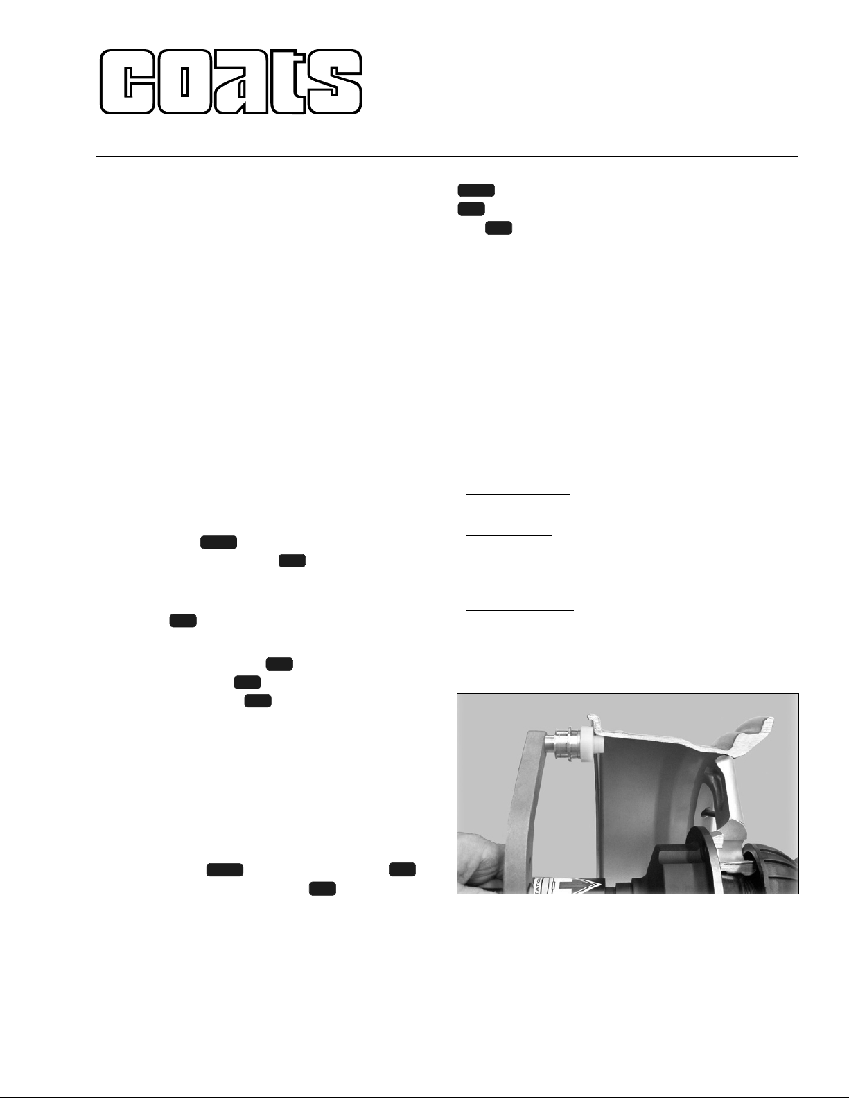
9. Refer to figure 1 showing the proper placement of
the metal arm roller on the rim.
Figure 1 - Placing The Metal Arm Roller On The Rim
10. See the new error code listing on the following
pages.
6
7
MENU
5
5
MENU
3
2
1
5
4
MENU
Page 2

Error
No
Video
Err. 1
Err. 2
Err. 3
Err. 4
Err. 5
Err. 6
Err. 7 /
Err. 8
Err. 9
Symptom
The balancer does not turn on.
Rotation signal missing.
Wheel spins too fast & no brake.
Balancer does not start.
Motor turns but no rotation.
Too low speed when taking the
measurement.
During rotation to measure the
unbalance value, the wheel
speed has gone below 42 r.p.m.
Calculation Error.
Incorrect Machine SelfCalibration.
Counterclockwise rotation.
After pushing START the wheel
turns in the opposite direction.
Wheel guard hood open or the
START button has been pushed
without closing the wheel guard
hood.
Ram Error or defect.
Reading error of NOVRAM parameters.
Access error in NOVRAM parameters writing.
Check
1. Check for proper connection to the power supply.
2. Check and replace fuses on the power PCB if necessary.
3. Check the monitor function - press monitor menu button. (see trouble
shooting tips)
4. Check control transformer output.
5. Check FS1 & FS2 fuses on power PCB.
6. Check power cable to main PCB & output at power PCB.
7. Replace power PCB.
8. Replace the main PCB.
1. Check the belt tightness.
2. Encoder disconnected, bad or damaged wiring, failed optical unit - no
reset signal.
3. Check hood switch operation.
4. Replace the encoder unit.
5. Motor disconnected or bad wiring - check for motor voltage at power
PCB - check circuit breaker - check machine power.
6. If motor hums - remove belt and check for motor rotation at pulley - if
rotation, replace capacitor.
7. Check for faulty power PCB or main PCB.
1. Very light / small wheel mounted on balancer - not enough inertia to
keep wheel rotating.
2. Check belt tightening.
3. Check the operation and adjustment of the encoder and in particular, the
reset signal. (in MACHINE SELF-TEST “green screen”, Pos counts from
0 to 255 and then 0 again). UP = cw, DOWN = ccw.
4. Replace the main PCB.
1. Check the wheel dimensions setting.
2. Check the piezo pick-ups connections - electrical & mechanical. (in
MACHINE SELF-TEST “green screen”, push on spindle shaft and verify
that both piezo outputs change.
3. Execute the 4-ounce weight (Machine Self-Calibration).
4. Mount a wheel having a known unbalance (lower than 4.00 ounces or
100 grams) and check the balancer reading.
5. Replace the PC board.
1. In MACHINE SELF-TEST “green screen” - check the operation of
UP/DOWN - RESET signals of the encoder.
2. Check the connection of the motor for correct rotation.
1. Reset the error by pushing button 7 = EXIT
2. Close the wheel guard hood and press START button.
3. Check operation of the wheel guard micro-switch.
4. Press the START button.
1. Reset NOVRAM & check operation or Replace PCB.
1. Repeat the entire balancer calibration.
2. Switch the balancer OFF.
3. Wait a minimum time of 1 minute (approx).
4. Switch the balancer ON and check the proper operation.
5. Replace the PCB board.
1. Replace the PCB board.
8113936 00 10/04 page 2 of 4
Page 3

Error
Err. 11
Err. 12
Err.13
Err.14
Err.17
Err.18
Err.15 /
Err.16 /
Err.19
Err.20
Err. 21
Err. 22
Err. 23
Err. 25
Err. 30
Err.40,41
42, 43
Err.45,
46, 47,
48
Err.50,
51, 52,
53
Symptom
High speed error.
During rotation to measure the
unbalance value, the wheel
speed has gone over 270 r.p.m.
Error in the unbalance measuring
cycle.
Error in the unbalance measurement.
Over ranging - too much unbalance
Wheel stopped before it was
positioned or before taking
runout reading.
Weight dispenser time out.
Error in calculating impulses
referred to the weight to cut
(impulses = 0). (weight dispenser)
STOP button pushed during the
weight dispenser operation.
Number of impulses referred to
the correction weight lower than
number of anticipated impulses.
(weight dispenser)
Clock error
Error in creating the runout graph.
Error in the reading of the values
which are used to create the
runout graph.
Error in the writing procedure of
the cursor for the current value of
the runout graph.
Check
1. Check for possible damage or dirt on the encoder disc - clean dirt with a
soft cloth - blow air across the optical units.
2. Check the operation and adjustment of the encoder and in particular, of
the reset signal. (in MACHINE SELF-TEST “green screen”, Pos counts
from 0 to 255 and then 0 again). UP = cw. DOWN = ccw.
3. Replace the main PCB.
1. Press EXIT and respin. Check PHASE in MACHINE SELF-TEST”green
screen”, if 180 deg diff., recalibrate & check piezos.
2. Check encoder adjustment and operation. (clearance .020” to .035”)
3. Check motor operation.
4. Check belt tightness.
5. Check hub nut tightness.
6. Replace the main PCB.
1. Press EXIT and respin. Check PHASE, VCO (dynamic), VCI (static) in
MACHINE SELF-TEST “green screen”.
2. Check the piezo pick-ups connection. (electrical & mechanical)
3. Check the balancer spindle connections.
4. Mount a wheel having a known unbalance (lower than 4 oz or 100
grams) and check the balancer readings.
5. Replace the PC board.
A.) Follow screen instructions for “heavy side” down balancing to bring
wheel unbalance into range and then balance normally.
B.) Follow instructions 1 thru 5 above.
1. Wheel too light - not enough inertia. Use heavier wheel.
2. Check positioning of sonar unit behind wheel.
1. Press MENU and 5 - turn OFF weight dispenser function.
1. Press MENU and 5 - turn OFF weight dispenser function.
1. Press MENU and 5 - turn OFF weight dispenser function.
1. Press MENU and 5 - turn OFF weight dispenser function.
1. Replace the PC board
Execute a new Runout measurement.
1. Execute a new runout measurement.
1. Execute a new runout measurement.
8113936 00 10/04 page 3 of 4
Page 4

Error
Err.54
Err.55
Err.56
Err.57
Err.58
Err 59
Err.65
Symptom
Error in the Sonar reading.
Sonar did not read any value.
Error in the Radial Sonar reading.
The values taken by the Sonar are
insufficient for a correct Radial
Runout measurement.
Error in the Lateral Sonar reading.
Sonar did not read any value.
Error in the Lateral Sonar reading.
The values taken by the Sonar are
insufficient for a correct Lateral
Runout measurement.
Error in the Radial & Lateral Sonar
reading. No value was read by
the Radial and Lateral Sonars.
Error in the Radial and Lateral
Sonar reading. The values taken
by the Radial and Lateral Sonars
are insufficient for a correct
Runout measurement.
Printer Not Connected.
Check
1. Before taking the measurement, make sure that the RADIAL RUNOUT
SONAR is properly positioned.
2. Check the RADIAL RUNOUT SONAR connection. Unplug and replug at
power PCB.
3. Check the power supplies on the power board.
4. Replace the RADIAL RUNOUT SONAR.
5. Check that the wheel doesn’t stop before making at least 3 complete
turns after the first braking impulse.
6. Check the belt tightening.
7. Replace the PC board
1. Before taking the measurement, make sure that the RADIAL RUNOUT
SONAR is properly positioned.
2. Check that the wheel doesn’t stop before making at least 3 complete
turns after the first breaking impulse.
3. Check the belt tightening.
4. Fit a medium-sized wheel (14” x 5-3/4”) and execute a Radial Runout
measurement. If error 55 doesn’t take place anymore, it means that the
inertia of the wheel that gave the problem is the cause of the wheel
stopping before the acquisition of the minimum number of values necessary for a reliable Runout measurement.
1. Before taking the measurement make sure that the LATERAL RUNOUT
SONAR is properly positioned.
2. Check the Lateral Runout Sonar connection. Unplug and Replug at
power PCB.
3. Check the power supplies on the power board.
4. Replace the LATERAL RUNOUT SONAR.
5. Check that the wheel doesn’t stop before making at least 3 complete
turns after the first braking impulse.
6. Check the belt tightening.
7 Replace the PC board.
1. Before taking the measurement, make sure that the LATERAL RUNOUT
SONAR is properly positioned.
2. Check that the wheel doesn’t stop before making at least 3 complete
turns after the first braking impulse.
3. Check the belt tightening.
4. Fit a medium-sized wheel (14”x5-3/4") and execute a Lateral Runout
measurement. If error 57 doesn’t take place anymore, it means that the
inertia of the wheel that gave the problem is the cause of the wheel
stopping before the acquisition of the minimum number of values necessary for a reliable Runout measurement.
1. Check actions in Error 54.
2. Check actions in Error 56.
1. Check actions in Error 55.
2. Check actions in Error 57.
1. Check serial connector at computer PCB.
2. Check serial connections inside cabinet at wire tray.
8113936 00 10/04 page 4 of 4
© COPYRIGHT 2004 HENNESSY INDUSTRIES AND COATS ALL RIGHTS RESERVED PRINTED IN U.S.A.
 Loading...