

Page 1
1601 J. P. Hennessy Drive, LaVergne, TN USA 37086-3565 615/641-7533 800/688-6359 www.ammcoats.com Manual Part No.: 85008884 01
HENNESSY INDUSTRIES INC. Manufacturer of AMMCO
®
, COATS®and BADA®Automotive Service Equipment and Tools. Revision: 06/08
READ these instructions before placing unit in
service KEEP these and other materials delivered
with the unit in a binder near the machine for
ease of reference by supervisors and operators.
1175 Wheel Balancer
Installation Instructions
Operating Instructions
Safety Instructions
Maintenance Instructions
®
See
Balancing Your
First Tire
on page 1.
Page 2

ii • Important: Always read and follow the instructions.
Page 3

Important: Always read and follow the instructions. • iii
Table of Contents
Important Safety Instructions . . . . . . . . .iv - vi
Owner’s Responsibility . . . . . . . . . . . . . . . . . . . . . .v
Operator Protective Equipment . . . . . . . . . . . . . . . .v
Definitions of Hazard Levels . . . . . . . . . . . . . . . . . .v
Safety Notices and Decals . . . . . . . . . . . . . . . . . . .vi
Standard Safety Devices . . . . . . . . . . . . . . . . . . . . .vi
Balancing Your First Tire . . . . . . . . . . . . . . . .1
Principle Operating Parts . . . . . . . . . . . . . . . . .2
Know Your Unit . . . . . . . . . . . . . . . . . . . . . . . . . . . .2
Power Switch . . . . . . . . . . . . . . . . . . . . . . . . . . . . . .2
Operating the Balancer . . . . . . . . . . . . . . .3 - 7
Wheel Mounting . . . . . . . . . . . . . . . . . . . . . . . . . . .3
Standard Back Cone Mounting . . . . . . . . . . . . . . . .3
Standard Front Cone Mounting . . . . . . . . . . . . . . . .3
Control Panel And Display . . . . . . . . . . . . . . . . . . . .4
Operation Functions Menu . . . . . . . . . . . . . . . . . . .5
Entering Wheel Dimensions . . . . . . . . . . . . . . . . . .6
Automatic Dimension Presetting . . . . . . . . . . . . . . .6
Exact Positioning of the Adhesive Weight
by Means of the Gauge with Clips . . . . . . . . . . . . .7
Result of Measurement . . . . . . . . . . . . . . . . . . . . . .7
Recalculation Of The Unbalance . . . . . . . . . . . . . . .7
Behind Spoke (Hidden Weight) . . . . . . . . . . . .8
Match Mount . . . . . . . . . . . . . . . . . . . . . . . . . .9
Correction Modes . . . . . . . . . . . . . . . . . . . . . .10
Manual Dimension Presetting (Use only in
particular cases or for test) . . . . . . . . . .11 - 12
Self-Calibration . . . . . . . . . . . . . . . . . . . . . . . .13
Display Saver . . . . . . . . . . . . . . . . . . . . . . . . .13
Maintenance Instructions . . . . . . . . . . . . . . .14
Diagnostic Procedures . . . . . . . . . . . . . . . . . .14
After Balance Vibration Problems . . . . . . . . . . . . . .14
Installation Instructions . . . . . . . . . . . . .15 - 16
Receiving . . . . . . . . . . . . . . . . . . . . . . . . . . . . . . . .15
Standard Accessories . . . . . . . . . . . . . . . . . . . . . .15
Features . . . . . . . . . . . . . . . . . . . . . . . . . . . . . . . . .15
Specifications . . . . . . . . . . . . . . . . . . . . . . . . . . . . .15
Electrical Requirements . . . . . . . . . . . . . . . . . . . . .15
Floor and Space Requirements . . . . . . . . . . . . . . .16
Unpacking the Unit . . . . . . . . . . . . . . . . . . . . . . . .16
Remove Balancer from Pallet . . . . . . . . . . . . . . . .16
Connect to Power . . . . . . . . . . . . . . . . . . . . . . . . .16
Initial Testing . . . . . . . . . . . . . . . . . . . . . . . . . . . . . .16
Hood Installation . . . . . . . . . . . . . . . . . . . . . . . . . .17
Page 4

iv • Important: Always read and follow the instructions.
IMPORTANT SAFETY INSTRUCTIONS
SAVE THESE INSTRUCTIONS
READ ALL INSTRUCTIONS
1. Eye and face protection recommendations:
“Protective eye and face equipment is required to
be used where there is a reasonable probability of
injury that can be prevented by the use of such
equipment.” O.S.H.A. 1910.133(a) Protective goggles, safety glasses, or a face shield must be provided by the owner and worn by the operator of
the equipment. Care should be taken to see that
all eye and face safety precautions are followed by
the operator. ALWAYS WEAR SAFETY GLASSES.
Everyday glasses only have impact resistant
lenses, they are not safety glasses.
2. Be sure that wheels are mounted properly, the hub
nut engages the arbor for not less than four (4)
turns, and the hub nut is firmly tightened before
spinning the wheel.
3. Read and understand this manual before operating. Abuse and misuse will shorten the functional
life.
4. Be sure the balancer is properly connected to the
power supply and electrically grounded.
5. Do not operate equipment with a damaged cord or
if the equipment has been dropped or damaged –
until it has been examined and repaired by a qualified serviceman.
6. Do not let cord hang over edge of table, bench, or
counter or come in contact with hot manifolds or
moving fan blades.
7. If an extension cord is necessary, a cord with a current rating equal to or more than that of the equipment should be used. Cords rated for less current
than the equipment may overheat. Care should be
taken to arrange the cord so that it will not be
tripped over or pulled.
8. Keep guards and safety features in place and in
working order.
9. Wear proper clothing. Safety toe, non-slip
footwear and protective hair covering to contain
hair is recommended. Do not wear jewelry, loose
clothing, neckties, or gloves when operating the
balancer.
10. Keep work area clean and well lighted. Cluttered
and/or dark areas invite accidents.
11. Avoid dangerous environments. Do not use power
tools or electrical equipment in damp or wet locations, or expose them to rain.
12. Avoid unintentional starting. Be sure the balancer
is turned off and power disconnected before servicing.
13. Disconnect the balancer before servicing.
14. Use only manufacturer’s recommended accessories. Improper accessories may result in personal injury or property damage.
15. Repair or replace any part that is damaged or worn
and that may cause unsafe balancer operation. Do
not operate damaged equipment until it has been
examined by a qualified service technician.
16. Never overload or stand on the weight tray or any
part of the balancer.
17. Do not allow untrained persons to operate machinery.
18. To reduce the risk of fire, do not operate equipment in the vicinity of open containers or flammable liquids (gasoline).
19. Adequate ventilation should be provided when
working on or operating internal combustion
engines.
20. Keep hair, loose clothing, fingers, and all parts of
body away from moving parts.
21. Use equipment only as described in this manual.
22. Use only manufacturer’s recommended attachments and accessories.
Page 5
Important: Always read and follow the instructions. • v
Owner’s Responsibility
To maintain machine and user safety, the responsibility of the owner is to read and follow these instructions:
• Follow all installation instructions.
• Make sure installation conforms to all applicable
Local, State, and Federal Codes, Rules, and
Regulations; such as State and Federal OSHA
Regulations and Electrical Codes.
• Carefully check the unit for correct initial function.
• Read and follow the safety instructions. Keep them
readily available for machine operators.
• Make certain all operators are properly trained,
know how to safely and correctly operate the unit,
and are properly supervised.
• Allow unit operation only with all parts in place and
operating safely.
• Carefully inspect the unit on a regular basis and
perform all maintenance as required.
• Service and maintain the unit only with authorized
or approved replacement parts.
• Keep all instructions permanently with the unit and
all decals/labels/notices on the unit clean and visible.
• Do not override safety features.
Operator Protective Equipment
Personal protective equipment helps make tire servicing safer. However, equipment does not take the
place of safe operating practices. Always wear durable
work clothing during tire service activity. Loose fitting
clothing should be avoided. Tight fitting leather gloves
are recommended to protect operator’s hands when
handling worn tires and wheels. Sturdy leather work
shoes with steel toes and oil resistant soles should be
used by tire service personnel to help prevent injury in
typical shop activities. Eye protection is essential during tire service activity. Safety glasses with side
shields, goggles, or face shields are acceptable. Back
belts provide support during lifting activities and are
also helpful in providing operator protection.
Consideration should also be given to the use of hearing protection if tire service activity is performed in an
enclosed area, or if noise levels are high.
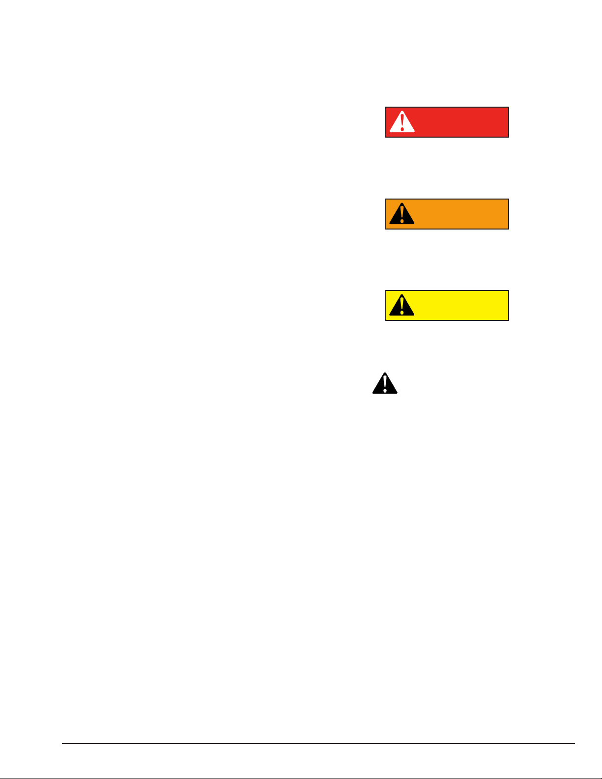
Definitions of Hazard Levels
Identify the hazard levels used in this manual with the
following definitions and signal words:
DANGER
Watch for this symbol:
It Means: Immediate hazards, which will result in
severe personal injury or death.
WARNING
Watch for this symbol:
It Means: Hazards or unsafe practices, which could
result in severe personal injury or death.
CAUTION
Watch for this symbol:
It Means: Hazards or unsafe practices, which may
result in minor personal injury or product or property
damage.
Watch for this symbol! It means BE ALERT! Your
safety, or the safety of others, is involved!
CAUTION
WARNING
DANGER
Page 6
vi • Important: Always read and follow the instructions.
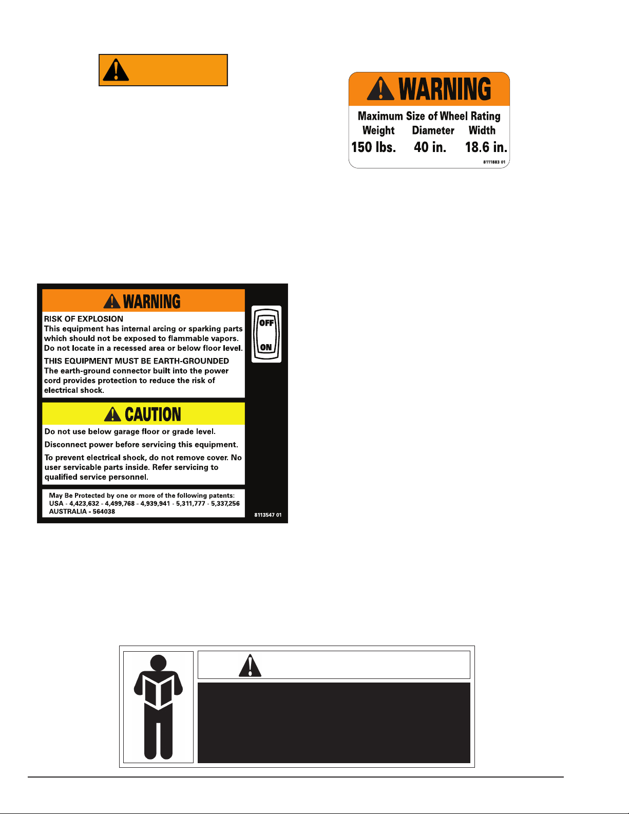
Safety Notices and Decals
Failure to follow danger, warning, and caution instructions may lead to serious personal injury or death to operator or
bystander or damage to property. Do not
operate this machine until you read and
understand all the dangers, warnings and
cautions in this manual. For additional
copies of either, or further information, contact:
Hennessy Industries, Inc.
1601 J.P. Hennessy Drive
LaVergne, TN 37086-3565
(615) 641-7533 or (800) 688-6359
www.ammcoats.com
Standard Safety Devices
• Stop push button for stopping the wheel under
emergency conditions.
• A hood guard of high impact plastic that is designed
to prevent the counterweights from flying out in any
direction except towards the floor.
WARNING
NOTICE
Read entire manual before assembling,
installing, operating, or servicing this
equipment.
Page 7
Important: Always read and follow the instructions. • 1
Balancing Your First Tire
1. Turn the machine OFF then ON
(resets machine).
Note: The machine wakes up using standard
clip-on wheel weight locations (c1 & c2) and
wheel dimensions.
2. Mount a tire/wheel on the
balancer that will use standard
clip-on wheel weights.
Use the most appropriate mounting method.
3. Always remove any weights
already attached to the wheel.
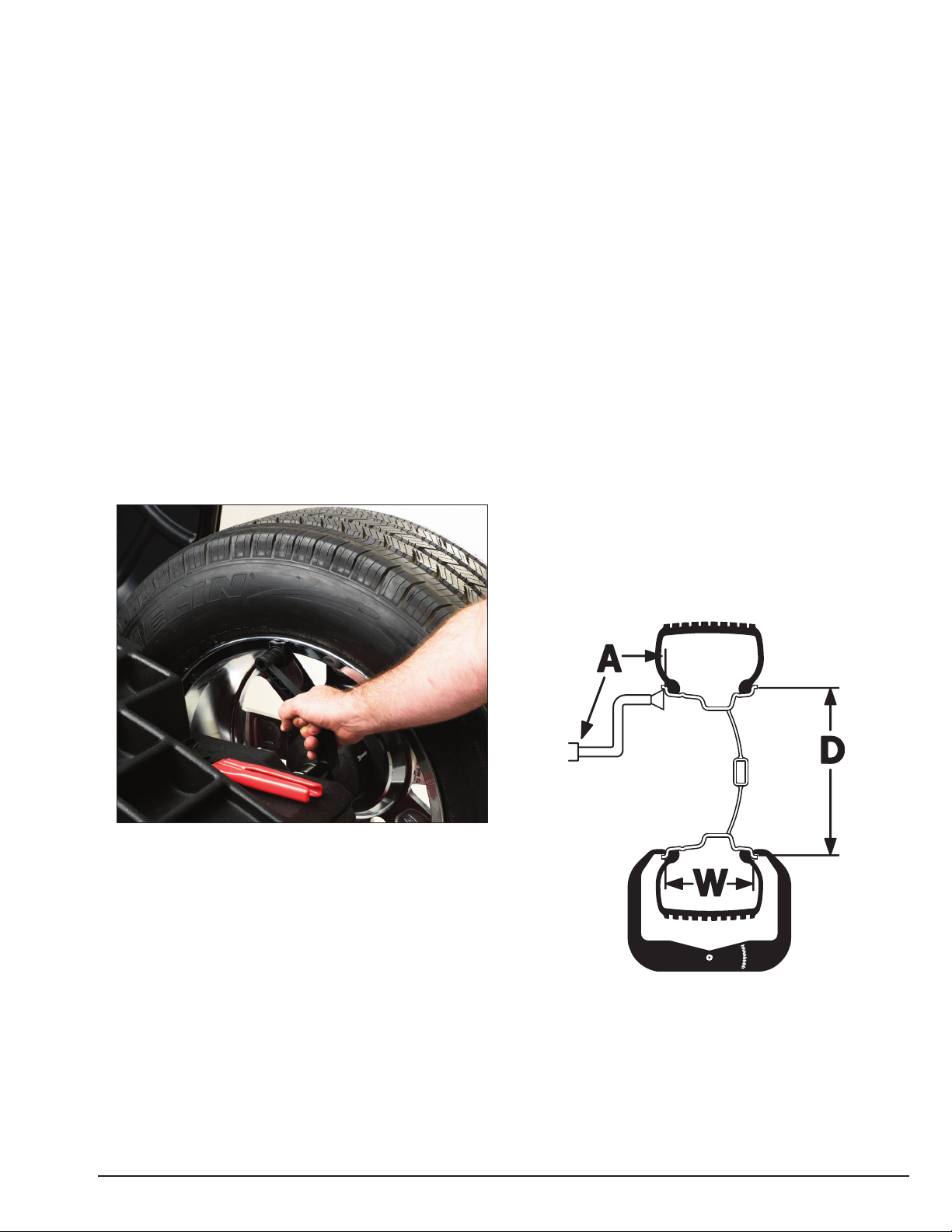
4. Enter A & D wheel dimensions
using offset arm.
Automatic Measurement — pull offset arm out
to the wheel, hold it still at clip-on weight
position against wheel flange. Return arm to
home position.
Offset
Arm At Clip-On Weight Location
5. Enter Width wheel dimension.
Use plastic calipers to measure wheel width.
Use keypad to enter Width value.
6. Lower the hood, press Start;
wheel spins and unbalances are
measured and displayed.
The corrective weight amount appears in the
digital readout windows.
7. Raise hood after tire stops rotating.
Note: Wait for wheel to stop before raising the
hood.
8. Rotate wheel to inboard (left
plane) position of unbalance.
9. Attach inboard (left plane)
corrective weight.
Attach specified weight amount at top-dead-center on inside flange of wheel.
10.Rotate wheel to outboard (right
plane) position of unbalance.
11.Attach outboard (right plane)
corrective weight.
Attach specified weight amount at top-dead-center on outside flange of wheel.
12.Lower the hood to respin the
tire/wheel and check balance.
Your weight readings should now be 0.00.
Note: Throughout this manual tire dimensions
are referred to as A, W, and D, see figure 2.
A, W, and D Tire Dimensions
Page 8
2 • Important: Always read and follow the instructions.
Principle Operating Parts
Do It Now!
Now is a good time to fill out
the Owner’s Registry Card.
✓
Note: Wheel weights are referred to as Clip-on or
Tape-A-Weight™. Figure 3 shows an example of each
weight.
Corrective Weight Examples: For Best Results, use BADA
®
Brand Wheel Weights.
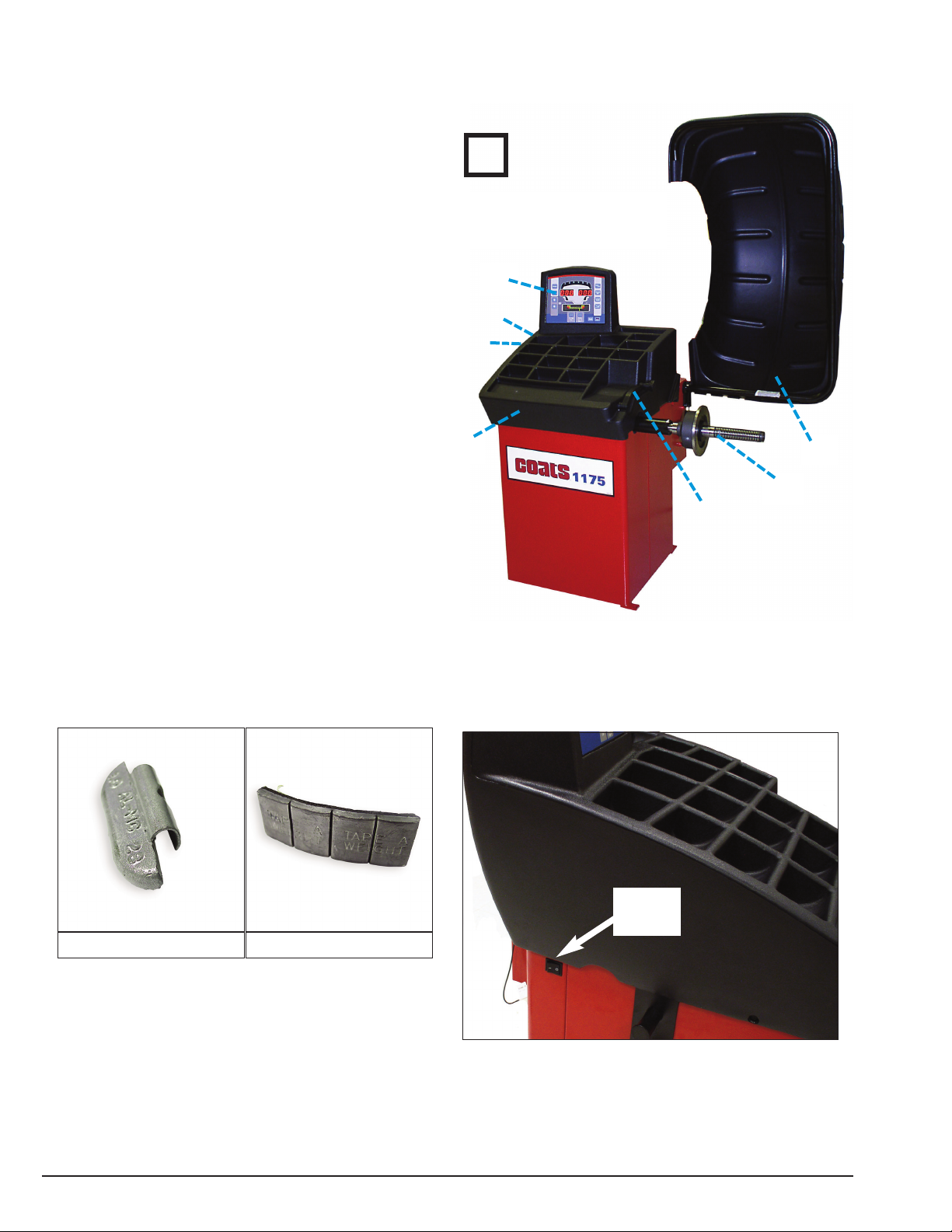
Power Switch
The ON/OFF switch location is on the side of the bal-
ancer; below the weight tray.
On/Off Switch
ON/OFF
Power
Switch
Clip-on Weight
Tape-A-Weight™
Know Your Unit
Compare this illustration with the unit before placing it
into service. Maximum performance and safety will be
obtained only when all persons using the unit are fully
trained in its parts and operation. Each user should learn
the function and location, of all controls.
Prevent accidents and injuries by ensuring the unit is
properly installed, operated and maintained.
Control Panel or Video Display Panel
Plug (back of machine)
ON/OFF
Weight Tray with Pockets for Corrective Weights
Offset Arm, Measures A & D of Tire/Wheel
(shown in home position)
40mm Shaft
Hood Guard
Page 9

Important: Always read and follow the instructions. • 3
Operating the Balancer
Wheel Mounting
Select the most appropriate mounting method for the
wheel you are balancing. Using the proper method
ensures secure mounting and safe balancer operation,
and prevents damage to the wheel.
On most wheels, the inner side of the wheel hub
usually has the most uniform surface for wheel balancing. Always center the wheel by the most uniform
shaped side of the hub to achieve the most accurate
balance.
Regardless of mounting type, always make sure that
the wheel is forced firmly against the shaft faceplate
and that the hub nut engages the threaded shaft for at
least four complete turns. To assist in centering the
wheel properly, rotate the wheel and the shaft while
tightening the hub nut.
Failure to tighten the hub nut properly may
result in the wheel dismounting, causing
personal injury and property damage.
Standard Back Cone Mounting
Most original equipment and steel wheels can be
mounted properly using this method. The wheel is centered on a cone from the inner side of the hub.
Back Cone Mounting
1. Select the cone that best fits the center hole in the
wheel. Slide the cone onto the shaft with the large end
towards the faceplate.
2. Lift wheel onto the shaft and center it on the cone.
3. Attach the pressure cup to the hub nut and install
the assembly onto the shaft. Tighten securely.
Note: Use a nylon spacer (no mar ring) to protect custom wheel finishes.
4. Thread the hub nut onto the shaft, and tighten it
against the wheel. The wheel must be forced firmly
against the faceplate. The hub nut must engage the
threads for at least three full turns.
Note: If the hub nut will not tighten completely, use
the front cone mounting method.
Standard Front Cone Mounting
A wheel should be centered by the outer side of the
hub only when the inner surface will not provide an
accurate surface to center on.
Front Cone Mounting
1. Select the cone that best fits the center hole in the
wheel.
2. Lift the wheel onto the shaft and slide it back
against the shaft faceplate.
3. Slide the cone onto the shaft and into the center
of the wheel. You will need to lift the tire to seat the
cone in the center hole.
4. Install the hub nut (without pressure cup) onto the
shaft. Tighten it securely against the cone. The hub nut
must engage the threads for at least three full turns.
Note: If the hub nut will not tighten completely
because of a lack of threads, use an additional cone as
a spacer between the mounting cone and the hub nut.
The wheel must be forced firmly against the faceplate.
CAUTION
Cone
Pressure Cup
Rim
Hub Nut
Rim
Hub Nut
Cone
Page 10

4 • Important: Always read and follow the instructions.
Control Panel And Display
1-2 Digital readouts, AMOUNT OF UNBALANCE,
inside/outside
3-4 Digital readouts, POSITION OF UNBALANCE,
inside/outside
5I INSIDE correction position selection button
5E EXTERNAL SIDE and STATIC correction
6 Push button, FUNCTIONS MENU
7 Push button, MENU selection confirmation
8 Maximize/MENU button
9 Minimize/MENU button
10 Push button, unbalance reading < 0.25 oz (5 g)
11 Push button, SPLIT
12 Position repeater push button
13 Push button, cycle start
14 Push button, emergency/EXIT
15 Dot matrix function display
16 oz/gr selection push button
1175 Control Panel
1
2
3
4
5I
5E
6
8
9
10
11
12
13
14
15
16
7
18
Note:
Only press buttons with your fingers. Never use the weight hammer or other pointed objects to press buttons.
Page 11

Important: Always read and follow the instructions. • 5
Operation Functions Menu
See optimization unbalance section
diameter
inch/mm
inch/mm
width
hood
start
approx.
0.1 -.25oz
or 1-5gr
on/off
beep
CONFIRM
CONFIRM
CONFIRM
CONFIRM
CONFIRM
CONFIRM
See SELF-DIAGNOSTICS section
See SELF-CALIBRATION section
display saver
operating time
in minutes
RETURN TO MEASUREMENT SCREEN
Calibration of automatic RIM DISTANCE gauge (see SETUP)
Calibration of automatic DIAMETER gauge (see SETUP)
Page 12

6 • Important: Always read and follow the instructions.
Entering Wheel Dimensions
For clip-on weights, use gauge in the top position A.
For adhesive weights, use the gauge as preferred in
top position A or bottom position B.
Note: Always use the round part of the striker plate
resting on the rim.
Indication of gauge in movement
Automatic Dimension Presetting
The machine automatically detects the correct bal-
ancing program for steel and aluminum rims.
The counterweight position proposed may be
changed using the 5I and 5E buttons.
Counterweights c1-c2/STATIC/t1-t3/c1-t3
Pull out the gauge as far as the inner edge of the rim.
Hold it in this position until a “beep” is heard.
Indication of dimensions acquired
Return the gauge to rest position. The machine has
automatically detected DISTANCE + DIAMETER and
goes to MANUAL WIDTH SETTING.
The nominal width is normally stamped on the rim; if
not, proceed to measure dimension “W” with the caliber gauge (supplied as standard).
Note: Once the dimensions have been set, you can in
any case change the correction method by pressing
the 5I and 5E buttons (see CORRECTION MODE).
Pos B
Pos A
W
W
Page 13

Important: Always read and follow the instructions. • 7
Exact Positioning of the Adhesive Weight
by Means of the Gauge with Clips
- press
- Fit the correction weight in the specific gauge seat
with the adhesive part facing upwards.
- bring the wheel into correct angular position for the
plane to be corrected
- withdraw the gauge until the correction plane indi-
cation arrows turn green
INSIDE CORRECTION POSITION
OUTSIDE CORRECTION POSITION
- Rotate the gauge until the correction weight adheres
to the rim
- the fact that the weight application position is no
longer vertical (Fig.8) is automatically compensated
- to cancel this function, press button
again
Result of Measurement
After performing a balancing spin, the amounts of
unbalance are shown on the digital readouts.
The illuminated LEDs 3 and 4 indicate the correct
angular position of the wheel to mount the counterweights (12 o’clock).
In the unbalance is less than the threshold valve
selected, 0 is displayed instead of the unbalance
value, with the values below the threshold
can be read.
Recalculation Of The Unbalance
Automatic on pressing the button.
Correction of inner side
Correction of outer side
FI
FE
Page 14

8 • Important: Always read and follow the instructions.
Behind Spoke (Hidden Weight)
The SPLIT function is used to position the adhesive
weights behind the wheel spokes so that they are not
visible. This function should be used only in the case of
static unbalance or where the hidden adhesive weight
is to be applied on the outside. Input the wheel dimensions and do a spin.
Start the SPLIT function as follows:
- Place the wheel in the outside unbalance correction
position.
- Set one of the top spokes (preferably the one to the
left of the unbalance) to 12 o’clock.
- Press
Indication of first positioning detected
- Follow the UP/DOWN indication of the arrows and
set the second top spoke to 12 o’clock.
- Press button
- Place the first Split unbalance in correction position 1
- Correction position 1 (indicator 1)
- Correction position 2 (indicator 2)
To return to normal unbalance display, press any but-
ton.
To carry out a new spin, press the button.
15
30
15
30
15
30
Page 15

Important: Always read and follow the instructions. • 9
Match Mount
- This function serves to reduce the amount of weight
to be added in order to balance the wheel
- It is suitable for static unbalance exceeding 1.5oz
(30g).
- It improves the residual eccentricity of the tire.
- With a piece of chalk make a reference mark on the
flange and the rim.
- With the aid of a tire remover, turn the tire on the rim
by 180˚.
- Refit the wheel in such a way that the reference
marks on the rim and the flange coincide.
- RH display: percentage reduction valve.
- LH display: actual static unbalance valve which can
be reduced by rotation.
RIM IN POSITION INDICATION
- Mark the tire (12 o’clock position).
TIRE IN POSITION INDICATION
- Mark the rim (12 o’clock position).
Turn the tire on the rim until the marks correspond to
obtain the optimization shown on the display.
CANCEL OPTIMIZATION IN ANY PHASE.
Unbalance
already measured
Unbalance measured
No previous
unbalance
measurement
Page 16

10 • Important: Always read and follow the instructions.
Correction Modes
From the measurement screen, press or
button to select the type required. If a
spin has already been performed, the processor automatically recalculates, for each change of mode, the
amounts of unbalance according to the new calculation.
Balancing of steel or light alloy rims
with application of clip-on weights on
the rim edges.
The static mode is necessary for
motorcycle wheels or when it is not
possible to place the counterweights
on both sides of the rim.
Balancing of light alloy rims with application of adhesive weights on the rim
shoulders.
Combined application: adhesive
weight outside and clip-on weight
inside.
Combined balancing: adhesive weight
on the inside and clip-on weight on the
outside.
Balancing of light alloy rims with hidden application of the outer adhesive
weights. The dimensions can be set.
(see MANUAL SETTING t1-t2)
Combined application: clip-on weight
inside and hidden adhesive weight on
outside (Mercedes). The dimensions
can be set. (see MANUAL SETTING
c1-t2)
To check the type of correction selected, hold the but-
ton , while on the matrix display the rim
symbol appears with the correction weights flashing in
the right application position.
This information remains displayed only as long as
the button is held down. To cancel any type of correction and return directly to dynamic unbalance, press
the button will put you back to c1-c2.
Page 17

Important: Always read and follow the instructions. • 11
Manual Dimension Presetting
(Use only in particular cases or
for test)
c1-c2/STATIC/t1-t3/c1-t3 Wheel Rims (use for
setting dimensions in AUTO CALIBRATION)
- Setting:
Press or
Set with the rated width that, in general,
is shown on the rim, or measure width “W” with the
caliper gauge supplied.
- Press the button for more than 2 seconds
- Preset using the nominal diameter “D”
indicated on the tire
- Press the button for more than 2 seconds
- Preset using distance “A” for the inside
of the wheel from the machine.
Note: This setting is also valid for the correction
modes STATIC/t1-t3/c1-t3.
t1-t2 Rims
- Setting:
To go to these functions:
- press one of the two buttons for more than 2 sec-
onds.
- to change press one of two buttons.
- to change press one of two buttons.
- to change press one of two buttons.
Note: when dt2 is not set, dt2 = dt1 + 1” is auto-
matic.
dt1
dt2
At1
At2
W
A
D
Page 18

12 • Important: Always read and follow the instructions.
c1-t2 Rims
- Setting:
To go to these functions:
- press one of the two buttons for more than 2 sec-
onds.
- to change press one of two buttons.
- to change press one of two buttons.
- to change press one of two buttons.
Note: when dt2 is not set, dt2 = dc1 + 2” is auto-
matic.
dc1
dt2
Ac1
At2
Page 19

Important: Always read and follow the instructions. • 13
Self-Calibration
For machine self-calibration proceed as follows:
- Fit a wheel with steel rim of average dimensions on
the shaft. Example 6" x 14" (± 1")
- Preset the exact dimensions of the wheel mounted.
IMPORTANT !! Presetting of incorrect dimensions
would mean that the machine is not correctly calibrated, therefore all subsequent measurements will be
incorrect until a new self-calibration is performed with
the correct dimensions!!
- Perform a spin under normal conditions.
- Add a 4.00 oz (ounce mode) or 100 gr. (gram mode)
calibration weight on outside in any angular position.
- Shift the caibration weight straight across to the
inside; keeping the same angular position.
- Rotate the wheel so to have the calibration weight
to the 12 o’clock position.
END OF SELF-CALIBRATION
CANCEL SELF-CALIBRATION IN ANY PHASE.
Display Saver
A display saver function can be enabled which allows
temporarily replacing the information on the display
with moving symbols. This function is activated when
the balancing machine is not used for longer than the
time set in the relevant setup:
Modifies the time expressed in minutes.
CONFIRM
Setting 0, the display saver is automatically disabled.
The display saver is not active in the setup menu of
the balancing machine.
To return to normal functioning of the balancing
machine, press any button or move the wheel.
Page 20

14 • Important: Always read and follow the instructions.
Maintenance Instructions
The balancer requires only minor maintenance to
keep the unit operating properly.
1. Keep the display clean and clear. Use a damp
cloth. Do not use cleaners or solvents which leave oily
or filmy residues behind.
2. Keep the adapters, cones, faceplate, threaded
shaft, pressure cup, and hub nut clean. Grease and dirt
buildup will cause inaccurate balancing and premature
wear. Clean these items at least once a day with a
vaporizing solvent.
3. Clean weight tray and any accessory posts, pegs,
or storage shelves with a vaporizing solvent. Weights
stored in a dirty tray may pick up grease and dirt which
may keep them from securely attaching to the wheel.
Use common sense, this is an electrical
device. Exposing the balancer to water,
either by hose or bucket, or by exposure to
rain or snow, may cause risk of shock or
electrocution to operator or bystanders.
Place, store, and operate the balancer only
in a dry, sheltered location.
Do not hose down with water or bucket
wash the balancer. Extensive damage to the
balancer will result. Sensitive electronic
components, wiring harnesses, and other
devices housed in the balancer are not
intended to be exposed to water.
4. Keep the area around the balancer clear. Remove
any tools or other items that are leaning against the
balancer. Keep the area under the balancer clear.
Remove any items that may cause the balancer to not
sit level. Be particularly cautious of new or used wheel
weights on the floor, as they may cause personal injury
due to falls.
5. Use only COATS®accessories. Accessories from
other manufacturers may not fit or function properly,
and may damage the balancer.
Diagnostic Procedures
After Balance Vibration Problems
If vibration is still present after balancing the wheels
and driving the vehicle on smooth pavement, remove
the wheels and recheck the balance. If a wheel is out
of balance the cause maybe:
• Wheel was not mounted/centered correctly on the
balancer.
• A weight has come off the wheel (possibly the
wrong clip style). Remove the other weights from
the wheel and rebalance.
• Foreign material inside the tire. Remove the tire
from the wheel, remove the foreign material, and
remount. Remove wheel weights and rebalance
the wheel.
• Stones or other foreign objects caught in the tire
tread or rim. Remove the objects. Check and rebalance if needed.
If the balancer still indicates the wheels are balanced
to within 0.10 ounces on both inner and outer displays,
the problem is not in the balance of the wheels. Check
the following possible sources of vibration:
• Tire pressure. Bring all tires up to the recommended PSI.
• Radial or lateral runout in the tire or wheel. Replace
the damaged part.
• Unbalance in wheel covers or trim rings. Remove
the wheel covers or trim rings and test drive. If the
vibration is gone, remove the shaft and use an
appropriate adapter to mount the wheel to the balancer. Balance the wheel with the wheel cover or
trim ring attached to the wheel.
• Incorrectly mounted wheel. Remount correctly.
• Damaged wheel bolt holes. Replace wheel.
• Worn universal joints. Replace as required.
• Drive shaft unbalance or damaged. Balance, repair,
or replace.
• Unbalance in brake rotor(s) or drum(s).
• Suspension out of alignment. Align the vehicle and
replace any damaged or worn parts.
CAUTION
WARNING
Page 21

Important: Always read and follow the instructions. • 15
Installation Instructions
A factory trained COATS®Service Technician must
perform the install, setup, and initial test procedures
on your wheel balancer. Do not attempt to install and
setup the unit yourself. Accurate and reliable operation
of your unit depends on proper installation. Please contact COATS®directly at 1-800-688-9240 for the
Certified Service Partner nearest you.
Receiving
The shipment should be thoroughly inspected as
soon as it is received. The signed bill of lading is
acknowledgement, for the carrier, of receipt in good
condition of the shipment covered by our invoice.
If any of the goods called for on this bill of lading are
shorted or damaged, do not accept them until the carrier makes a notation of the shorted or damaged goods
on the freight bill. Do this for your own protection.
NOTIFY THE CARRIER AT ONCE if any hidden loss or
damage is discovered after receipt and request him to
make an inspection. If the carrier will not do so, prepare an affidavit to the effect that you have so notified
the carrier (on a certain date) and that he has failed to
comply with your request.
IT IS DIFFICULT TO COLLECT FOR LOSS OR DAMAGE AFTER YOU HAVE GIVEN THE CARRIER A CLEAR
RECEIPT.
File your claim with the carrier promptly. Support your
claim with copies of the bill of lading, freight bill,
invoice, and photographs, if possible.
Although COATS responsibility ceases upon delivery
of the shipment to the carrier, we will gladly assist in
tracing lost shipments. Our willingness to assist in
every possible manner does not make COATS responsible for collection of claims, or replacement of lost or
damaged materials.
Standard Accessories
• Built-in Weight Tray
• 3 Back Cones
• Hub Nut
• Pressure Drum
• Rim Width Calipers
Features
• Balances Most Automotive Wheels
• Single-Spin Dynamic Two-Plane or Static Balancing
• Vertical Wheel Mounting
• Back Cone and Front Cone Mounting
• “No Bolt-Down” Installation
• Scratch Resistant Control Panel
• Easy-To-Read LEDs and Displays
• Automatic Calibration
• Removable Shaft Stud
• Automatic Rim Gauge Return
• Dynamic, Static, and Alloy Operating Modes
Specifications
• Weight (excluding adapter) 150 lbs.
• Single-phase power supply 220 V
• Protection class IP 54
• Max power consumption 0.8 Kw
• Balancing speed < 100 rpm
• Cycle time for average wheel (14 kg) 6-8 seconds
• Max.resolution of measurement .1 oz
• Position resolution ± 1.4 °
• Average noise < 70dB (A)
• Rim-machine distance 0 - 252 mm
• Rim width setting range 1.5 to 20 inches
• Diameter setting range 10 to 30 inches
Electrical Requirements
See serial tag for the appropriate power requirements
of your machine.
Always have a qualified electrician install the proper
receptacles in accordance with state and local codes.
Page 22

16 • Important: Always read and follow the instructions.
Floor and Space Requirements
The balancer must be located on a flat floor of solid
construction, preferably concrete. The balancer must
sit solidly on its three feet. If the balancer is not level,
does not sit solidly on its three feet, or is placed on an
unstable floor, the balancer will not function properly
and may produce inaccurate balance readings.
Do not operate the balancer while it is on the pallet.
Select a location for the balancer that provides a level,
solid floor, and adequate clearance around and above
the balancer. Make sure the location selected has
enough room above and behind the unit so the hood
can be raised completely. The location must also provide working room for mounting and removing wheels.
Make sure the area has adequate lighting
Space Requirements
Unpacking the Unit
1. Remove the shipping carton from the pallet.
2. Remove all loose parts and accessories packed
around the unit.
Remove Balancer from Pallet
3. Remove the shipping bolts that hold the balancer
to the pallet.
Do not use the control panel, control panel
base, accessory storage, faceplate, hood or
shaft to lift the balancer.
Use help to remove the balancer from the
pallet. The unit is heavy and the weight is
not evenly distributed. Dropping the unit
may cause personal injury or equipment
damage.
4. Lift the balancer off the pallet and place it in its
operating location.
5. Install and tighten the threaded stud into the end
of the motor shaft.
Connect to Power
Your factory trained COATS®Service Technician
should do the final check to verify the power installation before connecting the balancer to a power supply.
Failure due to improper power connection may void
the warranty.
Initial Testing
1. Plug the unit into an appropriate power outlet. If
the circuit breaker for the outlet is off, turn it on.
2. Turn the balancer on. The power switch is on the
back of the unit.
CAUTION
CAUTION
Page 23

Important: Always read and follow the instructions. • 17
Hood Installation
1. Install plastic bushing on end of hood tube.
2. Insert hood tube through hole and slide through
hood mounting bracket. The bushing will only fit one
way due to its molding.
3. Install second plastic bushing on the end of the
hood tube protruding from the bracket.
4. Slide on the stop ring. The set screws may need to
be loosened to install slide ring. Adjust the stop ring so
the notch is parallel to the floor when the hood is in the
down position.
5. Install the plug in the end of the hood tube.
6. Tighten the set screws to secure stop ring in
place.
7. Raise the hood.
8. Install hood spring. This attaches to the cam studs
on the hood bar and mounting bracket.
9. Lower the hood.
10. Screw on hood switch with two screws. The
height of the switch will need to be adjusted to ensure
the switch button is up when the hood is down. The
switch button should fit neatly in the cutout of the stop
ring.
11. Connect the switch wiring end to the three-
prong connector on the back panel of the chassis.
12. Test the hood switch with the auto spin feature
to ensure proper installation. If problems check the
height of the hood switch button for proper operation.
Page 24

85008884 01 06/08 © Copyright 2007 Hennessy Industries and COATS All Rights Reserved Printed in USA
 Loading...