

Page 1
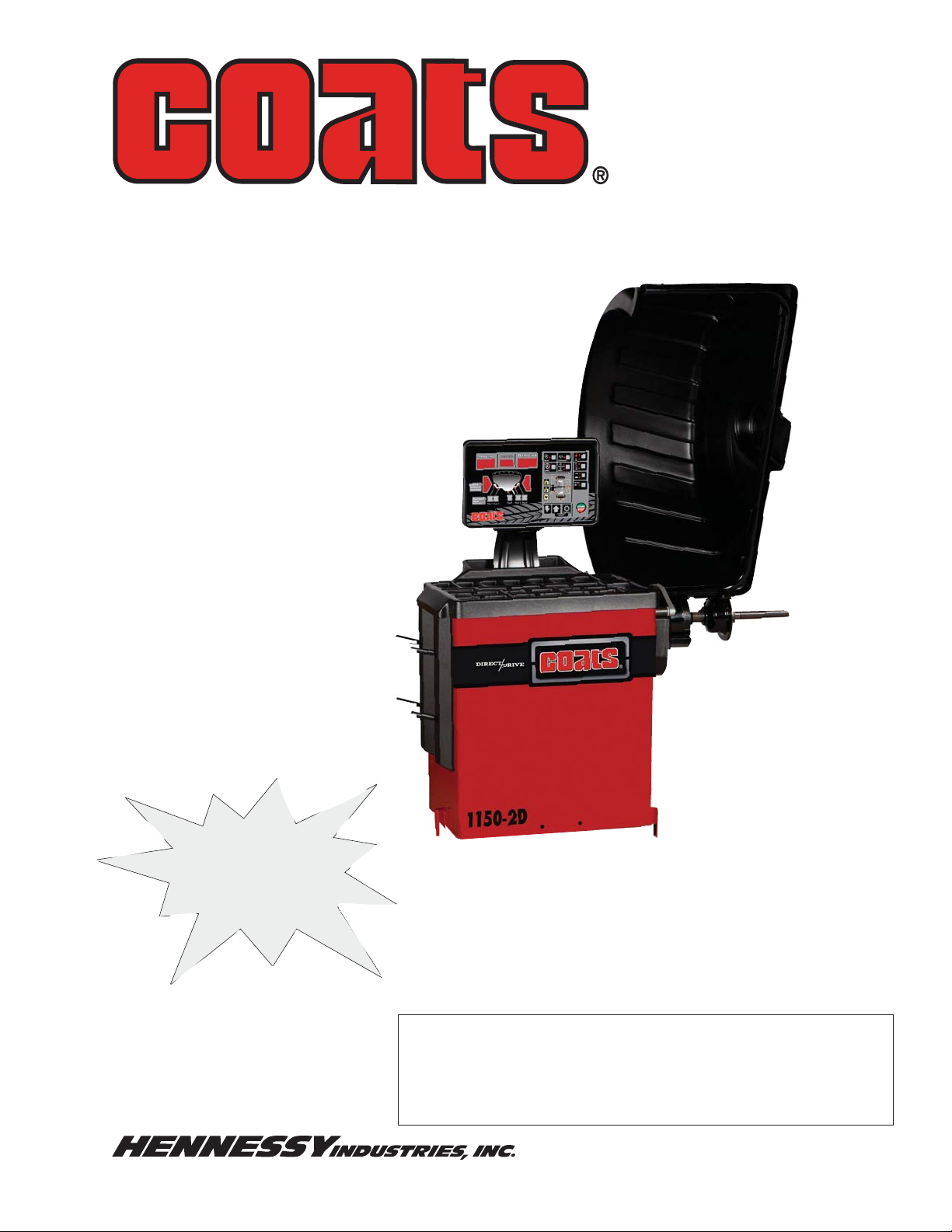
Models 1100,
1150-2D
Wheel Balancers
Model 1150-2D
See
ÌBalancing Your
First Tire
on page 4.
Safety Instructions
Shown
Set-up Instructions
Operation Instructions
Maintenance Instructions
READ these instructions before placing unit in
service. KEEP these and other materials delivered
with the unit in a binder near the machine for ease
of reference by supervisors and operators.
1601 J. P. Hennessy Drive, LaVergne, TN USA 37086 615/641-7533 800/688/6359 www.ammcoats.com Manual Part No.: 85609415 01
HENNESSY INDUSTRIES INC. Manufacturer of AMMCO
®
, COATS® and BADA® Automotive Service Equipment and Tools. Revision: 5/14
Page 2

IMPORTANT SAFETY INSTRUCTIONS
READ ALL INSTRUCTIONS
1. Eye and face protection recommendations:
“Protective eye and face equipment is required to
be used where there is a reasonable probability
of injury that can be prevented by the use of
such equipment.” O.S.H.A. 1910.133(a) Protective
goggles, safety glasses, or a face shield must be
provided by the owner and worn by the operator
of the equipment. Care should be taken to see
that all eye and face safety precautions are followed by the operator. ALWAYS WEAR SAFETY
GLASSES. Everyday glasses only have impact
resistant lenses, they are not safety glasses.
2. Do not disable hood safety interlock system, or in
any way shortcut safety controls and operations.
3. Be sure that wheels are mounted properly, the
hub nut engages the arbor for not less than four
(4) turns, and the hub nut is firmly tightened
before spinning the wheel.
4. Read and understand this manual before operating. Abuse and misuse will shorten the functional
life.
5. Be sure the balancer is properly connected to the
power supply and electrically grounded.
6. Do not operate equipment with a damaged cord
or if the equipment has been dropped or damaged – until it has been examined and repaired by
a qualified serviceman.
7. Do not let cord hang over edge of table, bench, or
counter or come in contact with hot manifolds or
moving fan blades.
8. If an extension cord is necessary, a cord with a
current rating equal to or more than that of the
equipment should be used. Cords rated for less
current than the equipment may overheat. Care
should be taken to arrange the cord so that it will
not be tripped over or pulled.
10. Wear proper clothing. Safety toe, non-slip footwear and protective hair covering to contain hair
is recommended. Do not wear jewelry, loose
clothing, neckties, or gloves when operating the
balancer.
11. Keep work area clean and well lighted. Cluttered
and/or dark areas invite accidents.
12. Avoid dangerous environments. Do not use power
tools or electrical equipment in damp or wet locations, or expose them to rain.
13. Avoid unintentional starting. Be sure the balancer
is turned off and power disconnected before
servicing.
14. Disconnect the balancer before servicing.
15. Use only manufacturer’s recommended accessories. Improper accessories may result in personal
injury or property damage.
16. Repair or replace any part that is damaged or worn
and that may cause unsafe balancer operation. Do
not operate damaged equipment until it has been
examined by a qualified service technician.
17. Never overload or stand on the weight tray or any
part of the balancer.
18. Do not allow untrained persons to operate machinery.
19. To reduce the risk of fire, do not operate equipment in the vicinity of open containers or flammable liquids (gasoline).
20. Adequate ventilation should be provided when
working on or operating internal combustion
engines.
21. Keep hair, loose clothing, fingers, and all parts of
body away from moving parts.
22. Use equipment only as described in this manual.
9. Keep guards and safety features in place and in
working order.
23. Use only manufacturer’s recommended attachments and accessories.
SAVE THESE INSTRUCTIONS
ii • Important: Always read and follow instructions.
Page 3
Owner’s Responsibility
To maintain machine and user safety, the responsibility
of the owner is to read and follow these instructions:
Definitions of Hazard Levels
Identify the hazard levels used in this manual with the
following definitions and signal words:
• Follow all installation instructions.
• Make sure installation conforms to all applicable
Local, State, and Federal Codes, Rules, and Regulations; such as State and Federal OSHA Regulations
and Electrical Codes.
• Carefully check the unit for correct initial function.
• Read and follow the safety instructions. Keep them
readily available for machine operators.
• Make certain all operators are properly trained,
know how to safely and correctly operate the unit,
and are properly supervised.
• Allow unit operation only with all parts in place and
operating safely.
• Carefully inspect the unit on a regular basis and
perform all maintenance as required.
• Service and maintain the unit only with authorized
or approved replacement parts.
• Keep all instructions permanently with the unit
and all decals/labels/notices on the unit clean and
visible.
• Do not override safety features.
Operator Protective Equipment
Personal protective equipment helps make tire servicing safer. However, equipment does not take the
place of safe operating practices. Always wear durable
work clothing during tire service activity. Loose fitting
clothing should be avoided. Tight fitting leather gloves
are recommended to protect operator’s hands when
handling worn tires and wheels. Sturdy leather work
shoes with steel toes and oil resistant soles should be
used by tire service personnel to help prevent injury
in typical shop activities. Eye protection is essential
during tire service activity. Safety glasses with side
shields, goggles, or face shields are acceptable. Back
belts provide support during lifting activities and are also
helpful in providing operator protection. Consideration
should also be given to the use of hearing protection if
tire service activity is performed in an enclosed area, or
if noise levels are high.
DANGER
Watch for this symbol:
DANGER
It Means: Immediate hazards, which will result in
severe personal injury or death.
WARNING
Watch for this symbol:
It Means: Hazards or unsafe practices, which could
result in severe personal injury or death.
CAUTION
Watch for this symbol:
CAUTION
It Means: Hazards or unsafe practices, which may
result in minor personal injury or product or property
damage.
Watch for this symbol! It means BE ALERT! Your
safety, or the safety of others, is involved!
Important: Always read and follow instructions. • iii
Page 4
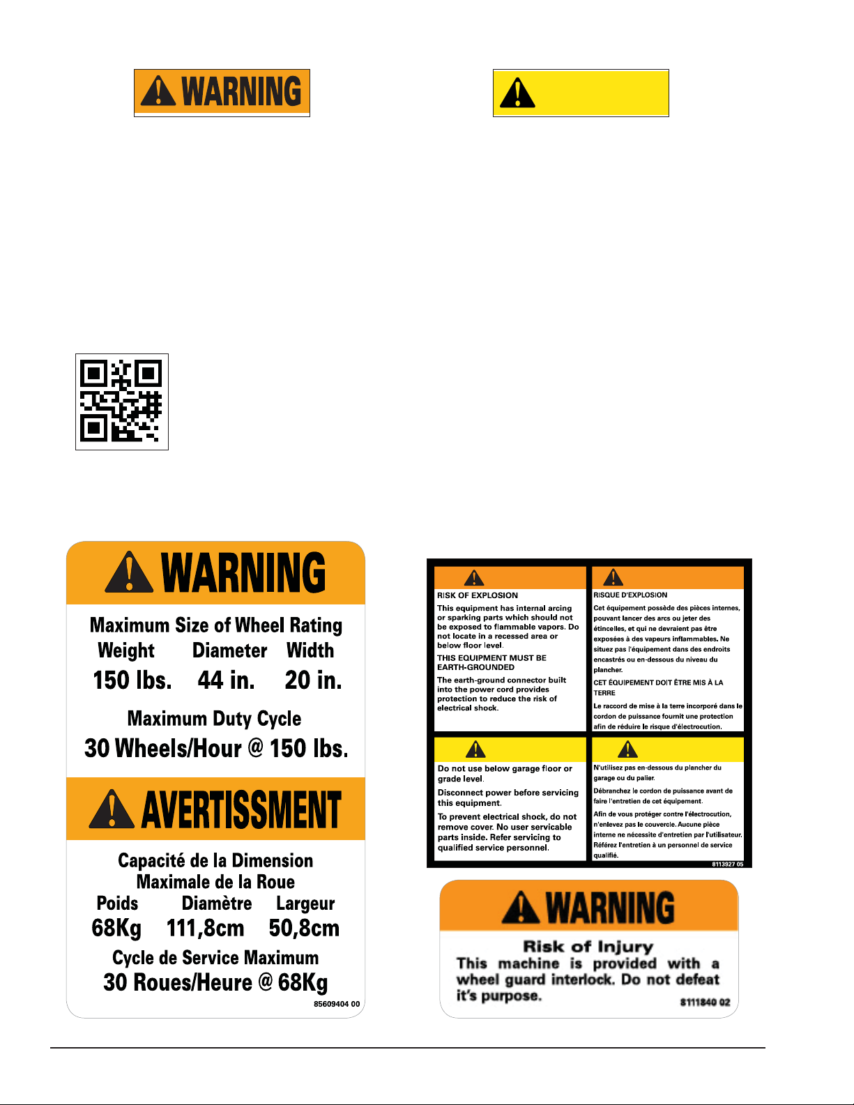
Safety Notices and Decals
Standard Safety Devices
CAUTION
Failure to follow danger, warning, and caution
instructions may lead to serious personal
injury or death to operator or bystander or
damage to property. Do not operate this
machine until you read and understand all
the dangers, warnings and cautions in this
manual. For additional copies of either, or
further information, contact:
Hennessy Industries, Inc.
1601 JP Hennessy Drive
LaVergne, TN 37086
(615) 641-7533 or (800) 688-6359
www.ammcoats.com
Never raise up the wheel guard before the
wheel has come to a stop. Keep hair, loose
clothing, fingers and all parts of body away
from moving parts.
• STOP key for stopping the wheel under emergency
conditions.
• A hood guard of high impact plastic that is designed
to prevent the counterweights from flying out in any
direction except towards the floor.
• A hood switch interlock system that prevents the
machine from starting if the guard is not lowered
and stops the wheel whenever the guard is raised.
WARNING
CAUTION
AVERTISSEMENT
ATTENTION
iv • Important: Always read and follow instructions.
Page 5

Table of Contents
Owner’s Responsibility............................................ iii
Operator Protective Equipment .............................. iii
Definitions of Hazard Levels ...................................iii
Safety Notices and Decals ......................................iv
Standard Safety Devices .........................................iv
Set Up Instructions .................................................. 2
Receiving ................................................................. 2
Electrical Requirements .......................................... 2
Machine Set Up ...................................................... 2
Floor and Space Requirements ............................... 2
Connect to Power ................................................... 2
Specifications ............................................................ 3
Features ..................................................................... 3
Accessory Options.................................................... 3
Basic Accessory Kit 85009974 ................................ 3
★Balancing Your First Tire ........................................ 4
Principle Operating Parts ......................................... 5
Know Your Unit ........................................................ 5
Power Switch .......................................................... 6
Using The Offset Arm .............................................. 6
Control Panel Layout ............................................... 8
Control Panel Function and Review ........................ 8
Mounting Wheel On Balancer Shaft ......................10
Standard Back Cone Mounting ..............................10
Standard Front Cone Mounting ..............................11
Alternate Mounting ................................................11
Direct Select™ Weight Location ........................... 12
Setting Wheel Dimensions (DIM) .......................... 12
Definition of Dimensions (DIM) ............................ 12
Basic Wheel Data Entry ........................................ 13
Entering Wheel Dimensions Manually .................. 13
Balancing A Wheel .................................................. 14
Dynamic Balancing ................................................ 14
Static Balancing ..................................................... 14
Behind Spoke Mode (1150-2D only) ...................... 15
Corrective Weight Placement ................................ 15
Match Balance (Optimization) .............................. 16
Match Balance Mode ............................................ 16
Calibration Program ............................................... 17
Machine Calibration ................................................17
Arm Calibration ...................................................... 18
Maintenance Instructions ...................................... 19
Diagnostic Procedures ........................................... 20
After Balance Vibration Problems .......................... 20
Troubleshooting ..................................................... 20
Glossary ................................................................... 22
NOTICE
Read entire manual before assembling,
installing, operating, or servicing this
equipment.
Important: Always read and follow instructions. • 1
Page 6
Set Up Instructions
Receiving
The shipment should be thoroughly inspected as soon
as it is received. The signed bill of lading is acknowledgement, for the carrier, of receipt in good condition
of the shipment covered by our invoice.
If any of the goods called for on this bill of lading are
shorted or damaged, do not accept them until the carrier makes a notation of the shorted or damaged goods
on the freight bill. Do this for your own protection.
NOTIFY THE CARRIER AT ONCE if any hidden loss or
damage is discovered after receipt and request him to
make an inspection. If the carrier will not do so, prepare
an affidavit to the effect that you have so notified the
carrier (on a certain date) and that he has failed to
comply with your request.
IT IS DIFFICULT TO COLLECT FOR LOSS OR DAMAGE AFTER YOU HAVE GIVEN THE CARRIER A CLEAR
RECEIPT.
File your claim with the carrier promptly. Support
your claim with copies of the bill of lading, freight bill,
invoice, and photographs, if possible.
Although COATS responsibility ceases upon delivery
of the shipment to the carrier, we will gladly assist
in tracing lost shipments. Our willingness to assist in
every possible manner does not make COATS responsible for collection of claims, or replacement of lost or
damaged materials.
Electrical Requirements
See serial tag for the appropriate power requirements
of your machine.
Always have a qualified electrician install the proper
receptacles in accordance with state and local codes.
Machine Set Up
CAUTION
Do not use the control panel, control panel
base, accessory storage, faceplate, hood or
shaft to lift the balancer.
CAUTION
Do not attempt to install and set up the unit
yourself. Contact COATS as noted below.
A factory trained COATS Service Technician must
perform the install, set up, and initial test procedures on
your wheel balancer. Do not attempt to install and set
up the unit yourself. Accurate and reliable operation of
your unit depends on proper installation. Please contact
COATS directly at 86-512-62620469 for the Certified
Service Partner nearest you.
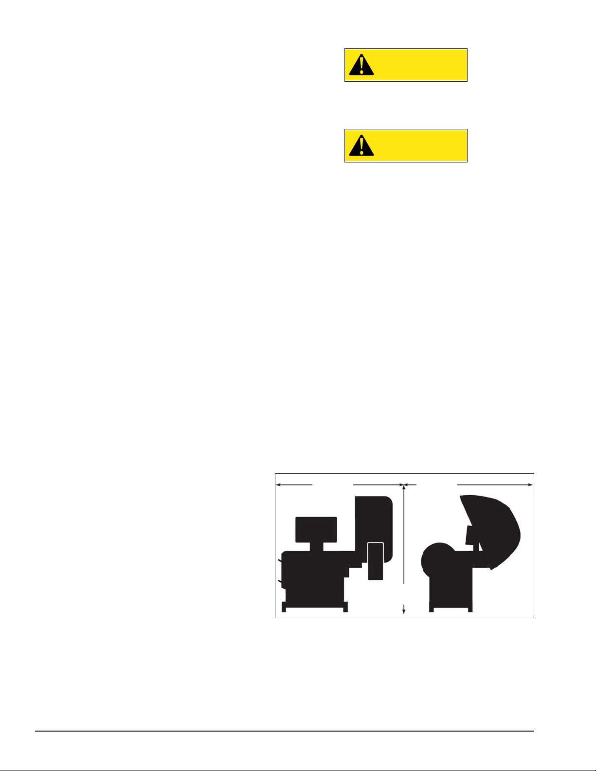
Floor and Space Requirements
The balancer must be located on a flat floor of solid
construction, preferably concrete. The balancer must
sit solidly on its three feet. If the balancer is not level,
does not sit solidly on its three feet, or is placed on an
unstable floor, the balancer will not function properly
and may produce inaccurate balance readings.
Do not operate the balancer while it is on the pallet.
Select a location for the balancer that provides a level,
solid floor, and adequate clearance around and above
the balancer. Make sure the location selected has
enough room above and behind the unit so the hood
can be raised completely. The location must also provide working room for mounting and removing wheels.
Make sure the area has adequate lighting.
5-ft.
(1529mm)
5-ft.
(1529mm)
6.5-ft.
(1981mm)
Figure 1 - Space Requirements
Connect to Power
Your factory trained COATS® Service Technician should
do the final check to verify the power installation before
connecting the balancer to a power supply. Failure due
to improper power connection may void the warranty
2 • Important: Always read and follow instructions.
Page 7

Specifi cations
Features
Wheel Diameter Range
8 - 30 inches (203 - 762 mm)
Wheel Width Range
2 - 20 inches (51 - 508 mm)
Maximum Outside Tire Diameter
Up to 44 inches (1016 mm)
Maximum Tire/Wheel Weight
150 pounds (68 Kg)
Mounting Shaft Diameter
40 mm
Resolution (Round Off Mode)
0.25 ounce, position 1.40 degrees
Resolution (Non-Round Off Mode)
0.01 ounce, position 1.40 degrees
Balancing Display Increments
0.25 or 0.01 ounces
Electrical Requirements
220V, 1 PH, 60 Hz, 20A
NEMA L6-20R
220V, 3 PH, 60 Hz, 20A
NEMA L15-20R
(use grounding type plug)
Footprint
Depth: 60 inches (1524 mm)
Width: 60 inches (1524 mm)
Shipping Weight
680 pounds (308 Kg)
(with accessories)
• Automatic Data Entry for Offset and Diameter - Manual Entry Backup on all Parameters (1150-2D only)
• Static-on-Screen™
• Direct Select™ Weight Placement Location
Dynamic (Standard): Clip-on Weights
Alloy: User Defined
Static
• Behind the Spoke Weight Placement (1150-2D only)
• Automatic Start When Hood is Lowered
• Single Spin Balancing - Dynamic and Static
• Easy-To-Read Position Indicators
• Hood Safety Interlock System
• Extended Mounting Faceplate for Deeper Wheels
• Removable Center Shaft for Closed Center Wheels
• Match Balance (Optimization)
• Operator Memory for Two Different Users
• User Friendly Weight and Position Calibration
• No Bolt-down Installation
• Solid State Motor Control
Accessory Options
Basic Accessory Kit 85009974
• Small Cone
• Medium Cone
• Large Cone
• Light Truck Cone
• Rim Width Calipers
• Wheel Weight Pliers
• Hubnut Handle
• Small Pressure Cup & Rubber Lip
• Cone Spring
• Scraper
• Cone Peg Brackets
Important: Always read and follow instructions. • 3
Page 8
★Balancing Your First Tire
1. Turn the machine OFF then ON
(resets machine).
The machine wakes up using
standard clip-on wheel weight
locations (Clip 1 & Clip 2) and
wheel dimensions.
2. Mount a tire/wheel onto
balancer that will use standard
clip-on wheel weights.
Use the most appropriate mounting method.
3. Always remove any weights
already attached to the wheel.
4. Enter A & D wheel dimensions
using offset arm.
For Automatic Measurement — pull offset arm
out to the wheel, hold it still at clip-on weight
position against wheel flange, and wait for
BEEP. Return arm to home position.
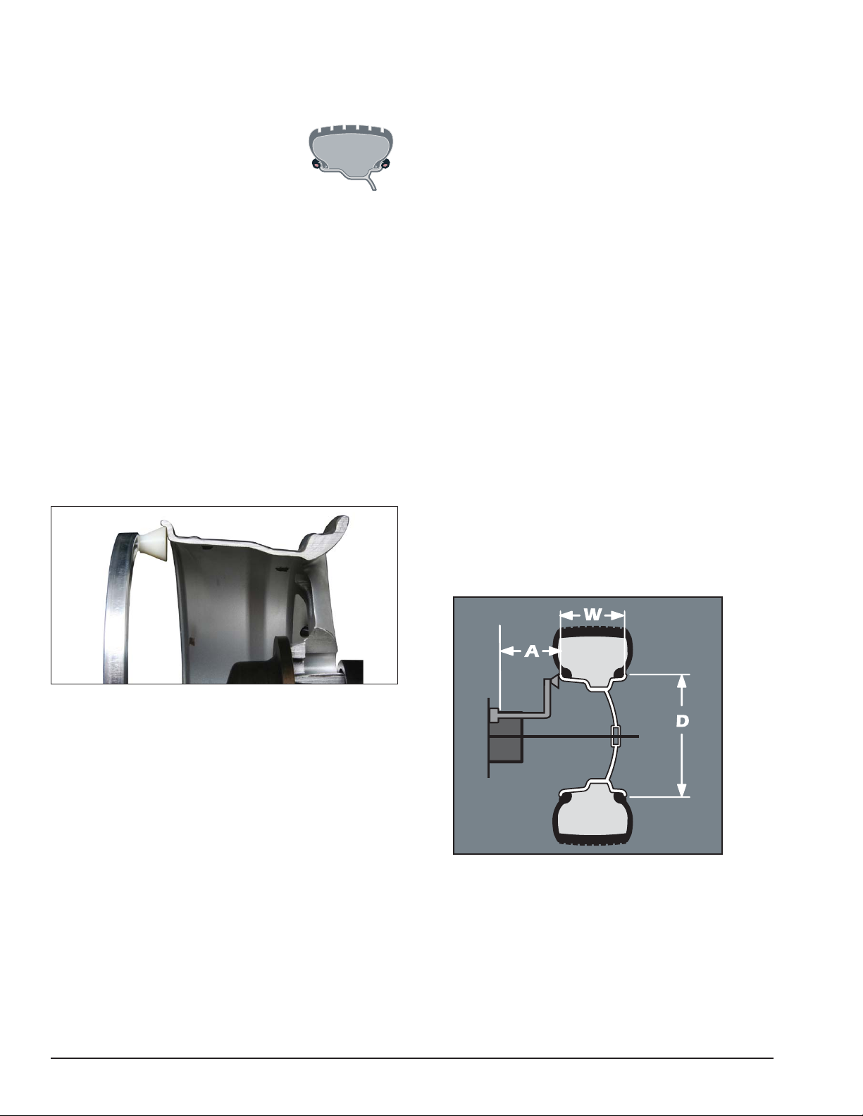
Clip-on Weight Location — viewed on a cut-
away rim for clarification.
7. Raise hood after tire stops
rotating.
Note: Wait for wheel to stop before raising the
wheel guard.
8. Rotate wheel until Inboard
weight position bar blinks.
Note: If an inboard corrective weight is not
required then go to step 10.
9. Attach inboard corrective
weight.
Attach specified weight amount at top-dead-
center on inside flange of wheel (clip 1).
10. Rotate wheel until Outboard
weight position bar blinks.
11. Attach outboard corrective
weight.
Attach specified weight amount at top-dead-
center on outside flange of wheel.
12. Lower the hood to respin the
tire/wheel and check balance.
Figure 2 - Clip-On Weight Location
Note the value entry of A & D dimension.
5. Enter Width wheel dimension.
For Manual Entry — Use plastic calipers to
measure wheel width. Press W key. Press Up
or Down arrow to enter Width value (between
2.0 and 14.0 inches).
6. Lower Wheel Guard; wheel spins
and unbalances are measured
and displayed.
The corrective weight amount appears in the
weight display window for inboard and outboard weight locations.
The weight readings should now be 0.00.
Note: Throughout this manual tire dimensions
are referred to as A, W, and D, see figure 3.
Figure 3 - A, W, and D Tire Dimensions
4 • Important: Always read and follow instructions.
Page 9
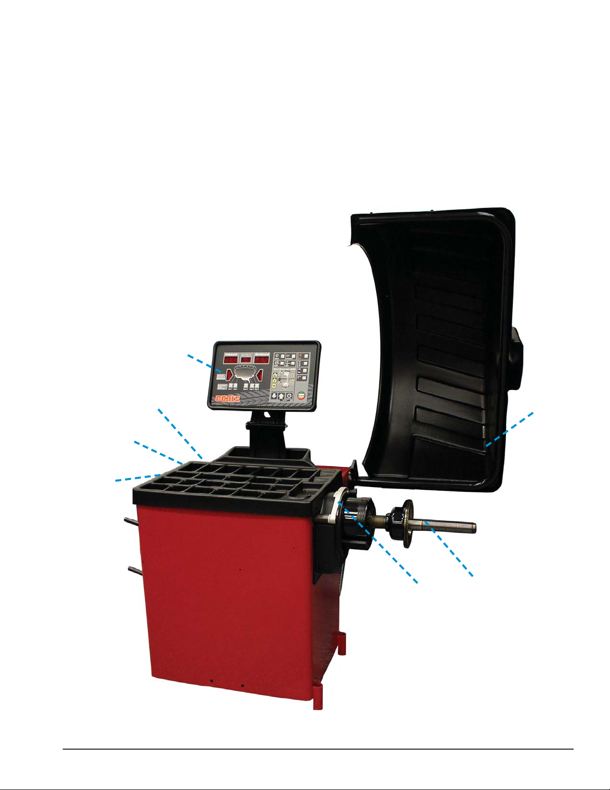
Principle Operating Parts
A
B
C
D
E
G
H
A
C
B
D
G
E
H
A - Control Panel
Know Your Unit
Compare this illustration with the unit before placing
it into service. Maximum performance and safety will
be obtained only when all persons using the unit are
fully trained in its parts and operation. Each user should
learn the function and location, of all controls.
Prevent accidents and injuries by ensuring the unit is
properly installed, operated and maintained.
B - ON/OFF Switch (back of machine)
C - Plug (back of machine)
D - Weight Tray with Pockets for Weights
E - Offset Arm, Measures A & D of Tire/Wheel
(Shown In Home Position)
G - 40 mm Shaft
H - Hood Guard
D
C
B
A
E
G
H
Important: Always read and follow instructions. • 5
Page 10

Note: Throughout this manual, wheel weights are
referred to as Clip-on or Tape-A-Weight®. Figure 4
shows an example of each weight.
Using The Offset Arm
When not in use or when prompted by the balancer
instructions, store the offset arm in the home position
as shown in figure 6.
Clip-on Weight Tape-A-Weight
Figure 4 - Corrective Weight Examples. For Best Results, use
BADA® Brand Wheel Weights.
®
Power Switch
The ON/OFF switch location (figure 5) is at the back
of the balancer; below the weight tray.
Offset Arm
In Home
Position
Figure 6 - Location of Offset Arm (Stored In Home Position)
When prompted by balancer instructions, use the
offset arm (figure 6) to enter A & D measurements
automatically. Pull the arm out and up against the wheel
flange; hold it still at the clip-on weight location (figure
7), against the wheel flange, and wait for the BEEP.
ON/OFF
Power
Switch
Figure 7- Automatic A & D Measurement At Clip-on Weight
Location
Figure 5 - On/Off Switch
6 • Important: Always read and follow instructions.
Page 11

Be sure to place the offset arm on the wheel flange at
the clip-on weight location as shown, figure 8.
Important: The A2 measurement must be at least 2
inches greater than the A1 measurement.
Figure 8 - Clip-on Weight Location Viewed on a Cut-Away Rim
for Clarification
Note: Use the offset arm to automatically measure
the A & D dimension for all balancing modes.
Note: Refer to page 13 to measure the A dimension
manually using the offset arm.
Note: The T2 Tape Direct™ Select Weight position is
the only mode that requires the A2 & D2 dimension
measurements.
A1 A2
At least
2-inch
minimum
difference
Figure 10 - T2 Tape (Hidden Tape-A-Weight®) Keep At Least
2-inches Between A1 and A2 Measurement
If the T2 Tape (hidden Tape-A-Weight®) location is
selected, use the offset arm to enter A2 & D2 measurements, automatically. After the A & D measurement is
entered, move the arm from the clip-on weight location
to the inner area of the wheel; up against the rim at the
Outboard weight placement location (see figures 9 &
10). Wait for the BEEP.
Figure 9 - Hidden Weight Location Viewed on a Cut-Away Rim
for Clarification
Figure 11 - T2 Tape (Hidden Tape-A-Weight
gram
®
) Data Entry Dia-
Important: Always read and follow instructions. • 7
Page 12

Control Panel Layout
7
4
6
5
3
2
2
1
1
2
3
4
2
3
1
2
4
5
7
6
Figure 12 - Control Panel Feature Reference (Model 1150 Shown)
Control Panel Function and Review
1 Weight Display Windows
Two weight display windows, one Inboard and one Outboard, are positioned above the Wheel Cross-section
Diagram. After a wheel measurement cycle, the balancer calculates the corrective weight amount and indicates
it in the appropriate display window. All weight readings are shown in Ounces or Grams. Also displays A, W,
and D values, functions, and instructions for the operator. Error messages will also be shown in this display.
The Total Static window indicates the value of the total static unbalance. See MATCH BALANCE (Optimization)
on page 16 for further details.
2 Weight Position Bars
Located on either side of the wheel cross-section diagram are the weight position bars, one Inboard and one
Outboard. After a measurement cycle, rotate wheel until the center weight position bar blinks, indicating the
correct weight placement position is at top-dead-center.
Key Group If you press/select ... Then indicator illuminates/displays...
3 Direct Select™ Weight Keys & Wheel Cross-section Diagram
Clip 1, or T1 Tape
, or
T2 Tape, T3 Tape or Clip 2
, or
the activated Inboard weight location
on the wheel cross-section diagram.
the activated Outboard weight location
on the wheel cross-section diagram.
4 Wheel Dimensions (DIM) Keys & Measurement Diagram
, , or
A, D, or W
A2+Function or D2+Function
+ or +
the activated wheel measurement
location. The default is Clip 1 and Clip 2.
Enter wheel data manually using either
the Up or Down arrow key.
8 • Important: Always read and follow instructions.
Page 13

Key Group If you press/select ... Then indicator illuminates/displays...
5
6
7
5 Balance Mode Keys
+
6 Balance Option Keys
Match
Spoke (1150-2D only)
Calibration
Function+Calibration that Arm Calibration mode is activated.
Dynamic or Static
A or B
Ounce or Gram
Car or Light Truck
Round Off
that Match Balance (Optimization)
mode is activated.
that Behind Spoke mode is activated
Toggle to activate / select location 1 or
location 2 for adhesive weights.
that Machine Calibration mode is
activated.
the Balance mode that is activated.
Scroll to select Dynamic (default),
Dynamic/Total Static or Static.
the Operator Memory option that is
activated. Toggle between two operator
memories A (default) or B.
the weight measurement option that is
activated. Toggle to select either Ounce
(default) or Gram.
the weight increment option that
is activated. Toggle to select either
0.25-ounce passenger car (default) or
0.50-ounce RV-Lt Truck (heavy wheels).
the weight increment option
0.25-ounce (default) is activated. Toggle
off to select 0.01-ounce (fine).
7 Navigation Keys
Down Arrow or Up Arrow
or
Function
EXIT that the function or error is deactivated.
START / STOP
the data entry values. Scroll to select
desired value.
the activated function. Usually used in
combination with another key.
that measurement cycle is either
begun (hood lowered) or is halted.
Important: Always read and follow instructions. • 9
Page 14

Mounting Wheel On Balancer
Shaft
CAUTION
Avoid back injury, seek assistance when
lifting heavy tire/rim assemblies onto the
balancer shaft.
CAUTION
Failure to tighten the hub nut properly may
result in the wheel dismounting, causing
personal injury and property damage.
Select the most appropriate mounting method for
the wheel you are balancing. Using the proper method
ensures secure mounting and safe balancer operation,
and prevents damage to the wheel.
On most wheels, the inner side of the wheel hub usually has the most uniform surface for wheel balancing.
Always center the wheel by the most uniform shaped
side of the hub to achieve the most accurate balance.
Regardless of mounting type, on standard units,
always make sure that the wheel is forced firmly against
the shaft faceplate and that the hub nut engages the
threaded shaft for at least four complete turns. To assist
in centering the wheel properly, rotate the wheel and
the shaft while tightening the hub nut.
Standard Back Cone Mounting
Most original equipment and steel wheels can be
mounted properly using this method. The wheel is
centered on a cone from the inner side of the hub.
Faceplate
Cone
Spring
Figure 13 - Standard Back Cone Mounting
1. Place the cone spring onto the balancer shaft with
the large end towards the faceplate.
2. Select the cone that best fits the center hole in the
wheel. Slide the cone onto the shaft with the large end
towards the cone spring.
3. Lift wheel onto the shaft and center it on the cone.
4. Attach pressure cup to hub nut. Install the hub nut
assembly onto the shaft and tighten it securely against
the wheel. The wheel must be forced firmly against the
faceplate. The hub nut must engage the threads for at
least four full turns
Note: Use a nylon spacer (protective ring) to protect
custom wheel finishes.
Shaft
Cone
Protective
Ring
Pressure Cup and
Quick Lock Hub Nut
Note: If the hub nut will not tighten completely, use
the front cone mounting method.
10 • Important: Always read and follow instructions.
Page 15

Standard Front Cone Mounting
A wheel should be centered by the outer side of the
hub only when the inner surface will not provide an
accurate surface to center on.
Alternate Mounting
If the wheel has a protruding outer hub which will not
permit the use of the pressure cup, or the cup will not
permit the hub nut to engage at least four turns of the
shaft, this alternate method should be used.
Faceplate
Figure 14 - Front Cone Mounting
Shaft
Cone
Quick Lock
Hub Nut
1. Select the cone that best fits the center hole in
the wheel.
2. Lift the wheel onto the balancer shaft and slide it
back against the faceplate.
3. Slide the cone onto the shaft and into the center
hole of the wheel. You will need to lift the tire to seat
the cone in the center hole.
4. Install the hub nut (without pressure cup) onto the
shaft. Tighten it securely against the cone. The hub nut
must engage the threads for at least four full turns.
Note: If the hub nut will not tighten completely
because of a lack of threads, use an additional cone as
a spacer between the mounting cone and the hub nut.
The wheel must be forced firmly against the faceplate.
Faceplate
Cone
Spring
Figure 15 - Alternate Mounting
Shaft
Cone
No-Mar
Ring
Quick Lock
Hub Nut
1. Place the cone spring onto the balancer shaft with
the large end towards the faceplate.
2. Select the cone that best fits the center hole in the
wheel. Slide the cone onto the shaft with the large end
towards the faceplate.
3. Lift wheel onto the shaft and center it on the cone.
4. Use the small nylon spacer (no-mar ring) or a
centering cone to press against the outer wheel hub.
5. Install the hub nut (without the pressure cup) onto
the shaft. Tighten securely.
Important: Always read and follow instructions. • 11
Page 16

Direct Select™ Weight Location
Setting Wheel Dimensions (DIM)
Before spinning the wheel, use direct select to indicate
weight placement locations on the wheel as follows:
Figure 16 - Direct Select™ Weight Keys & Wheel Crosssection Diagram
Note: When the machine is turned ON, the balancer
defaults to a 2-plane dynamic mode using standard
clip-on wheel weight locations (Clip 1 and Clip 2) and
wheel dimensions.
Clip 1 (default) - select this location to place a stan-
dard clip weight on the Inboard rim flange.
Before a wheel can be balanced, wheel dimensions
must be entered into the computer.
Definition of Dimensions (DIM)
A = Offset
The distance measured from the balancer (“0” on offset arm) to inner plane of the rim (inner weight location).
W = Width
The width of the wheel at the rim flanges, measured
with the calipers as shown in figure 19.
Note: Only use calipers provided by the wheel bal-
ancer manufacturer because others may not be the
same.
D = Diameter
The diameter of the wheel as indicated on the tire.
Note: A thick flange, on some aluminum wheels, can
effect the measured diameter. For example, a 16-inch
rim can have a measured diameter of 15.5-inches.
T1 Tape - select this location to place an adhesive
weight on the Inboard side of the wheel that is the
horizontal plane at the outer edge.
T2 Tape - select this location to place an adhesive (hid-
den) weight on the Outboard side of the wheel that is
the horizontal plane in the inner area.
T3 Tape - select this location to place an adhesive
weight on the Outboard side of the wheel that is the
horizontal plane at the outer edge.
Clip 2 (default) - select this location to place a stan-
dard clip weight on the Outboard rim flange.
Figure 17 - W, D, and A Tire Dimensions
A2 = Offset
The distance measured from the balancer (“0” on
offset arm) to outer plane of the rim (outer weight location). Used only for adhesive weight location.
D2 = Diameter
The diameter as measured at the A2 weight location.
Used only for adhesive weight location.
Figure 18 - A2 and D2 Tire Dimensions
12 • Important: Always read and follow instructions.
Page 17

Basic Wheel Data Entry
1. Direct Select™ an Inboard weight location (Clip 1,
or T1 Tape) and an Outboard weight location (T2 Tape,
T3 Tape or Clip 2).
2. Position offset arm at clip weight location; wait for
BEEP (A & D enters automatically).
If the T2 Tape location is selected, then move the
offset arm from the clip weight location to the inner
area of the wheel; up against the rim at the outboard
weight placement location; wait for BEEP (A2 & D2
enters automatically).
Entering Wheel Dimensions Manually
Information entered into the balancer software for A,
W, and D can be changed anytime during a balancing
procedure by entering the measurements manually. The
balancer will recalculate weights and positions based on
the new measurements.
Wheel Offset - A
1. Press the A (wheel offset) key.
2. Position offset arm at weight location on wheel and
read the number on the offset arm gauge, at the cabinet
(this is the correct offset A DIM).
3. Return offset arm to the home position.
4. Use caliper and measurement rim width.
5. Use UP / DOWN arrows to adjust the W (Width
DIM) to match measured caliper width of mounted rim.
6. Lower hood and spin wheel.
3. Use UP / DOWN arrow to adjust the measurement.
Wheel Diameter - D
1. Press the D (wheel diameter) key.
2. Inspect mounted tire sidewall to determine the
exact diameter this is printed on the tire.
3. Use the UP / DOWN arrow to adjust the D (Diam-
eter DIM) to match the tire sidewall size.
Note: Auto entry is the preferred method for entering A2 and D2. However, to manually enter A2, press
Function+A and hold. And to enter D2, press Function+D
and hold.
Wheel Width - W
1. Press the W (wheel width) key.
2. Use the plastic calipers provided with the wheel
balancer to measure the wheel width.
Figure 19 - Caliper Placement On Wheel
3. Use UP / DOWN arrows to adjust the W (Width
DIM) to match measured caliper width of mounted rim.
Important: Always read and follow instructions. • 13
Page 18

Balancing A Wheel
A variety of wheel configurations can be balanced
using this wheel balancer. Read through this section,
it will help in determining which balancing mode and
options are best suited for certain wheel assemblies.
Remember: As with any balancing procedure, first
remove any weights attached to the wheel, inspect the
tire and wheel, and use the most appropriate balancer
mounting method before beginning.
Dynamic Balancing
Choose a dynamic balance to balance a wheel using
two planes for correction. Select the weight option that
best fits the available weight locations on the rim.
Clip-on Weights - The standard default; used for most
passenger tire/wheel assemblies using the most common location for corrective weights. Clip-on weights
are placed on the inner (inboard) and outer (outboard)
rim flanges.
ALUS (Aluminum Wheels) - To balance aluminium
wheels you usually use a self-adhesive weight location
that is positioned differently from the clip-on weight
position(s) used in standard balancing. Be sure to use
the appropriate wheel data entry method since the
balancer calculates out of balance values based on the
wheel dimension measurements (DIM) entered for the
tire/wheel assembly.
Static Balancing
Choose a static balance to balance a wheel using one
plane for correction. Place the single corrective weight
at top-dead-center (12 o’clock) on either flange, at the
center of the rim channel, placed inward either side, or
split on either sides.
Figure 21 - Static Balance Weight Locations
Note: When in static mode, you only need to input the
DIAMETER wheel measurement.
Important: If you decide to use the rim channel for
corrective weight placement, remember you may need
to adjust the DIAMETER measurement input. Typically
you would make it 2 or 3 inches less than the actual tire/
wheel diameter.
Figure 20 - Dynamic Balance Weight Locations
Note: When the machine is switched on, a standard
dynamic balance using clip-on weight locations is the
default setting.
14 • Important: Always read and follow instructions.
Page 19

Behind Spoke Mode (1150-2D only)
“Splitting” the T2 Tape corrective weight amount is
used to hide the adhesive weight behind two rim
spokes.
1. When the unbalance is displayed, rotate wheel
until Inboard center bar blinks. Attach Inboard corrective
weight at top-dead-center.
2. Next, rotate wheel until the outboard center bar
blinks.
3. Select the Behind Spoke mode option. “SP1” will
display in the static display window.
4. Rotate the wheel toward front until the first spoke
is at top-dead-center.; press Spoke and 1 illuminates.
“SP2” will display in the static display window.
5. Rotate the wheel toward rear until the second
spoke is at top-dead-center; press Spoke and 2 illuminates. Now at the Spoke 2 location, the Outboard
center bar stops blinking.
Corrective Weight Placement
After the wheel spins and out of balances are measured and displayed, the corrective weight amount
appears on the weight display window for Inboard and
Outboard weight locations. Bars appear on either side
of the wheel cross-section diagram to aid in positioning
the wheel for corrective weight at the application point.
After a measurement cycle, rotate wheel until the
center weight position bar blinks, indicating the correct weight placement position is at top-dead-center.
If the out-of-balance is less than the chosen threshold
value, 000 appears instead of an out-of-balance value
to indicate that, on that particular side, the wheel is in
tolerance.
Figure 22 - Spoke 1 and Spoke 2 Locations On Either Side Of
Original Outboard Weight Location
6. Attach the Spoke 2 Outboard corrective weight at
top-dead-center behind spoke 2.
7. Next, rotate the wheel toward the Spoke 1 location
until the outboard center bar is blinking.
8. Attach the Spoke 1 Outboard corrective weight at
top-dead-center behind spoke 1.
9. Respin tire/wheel to check balance.
Important: Always read and follow instructions. • 15
Page 20

Match Balance (Optimization)
Match Balance involves the loosening of
tire beads and the inflation of a tire. Training
is necessary in tire changer operation and
understanding the dangers involved during bead seating and tire inflation before
attempting this stage of the Match Balance
procedure. Read the operators manual supplied with the tire changer and consult a
supervisor.
Use the Match Balance (Tire/Rim Weight Optimization)
program to determine the best mating of tire and rim
that will result in the least amount of total unbalance of
the assembly. It requires two spins and two rotations
of the tire on the rim. Match Balance may be needed
when:
• The customer complains of ride problems.
• The balancer calculates a high out of balance.
• The balancer calls for Total Static weights in excess
of 3 ounces (85 grams) on passenger car tires.
Match Balance Mode
If you choose to use Match Balance to correct for a
condition, such as a large static unbalance, then follow
the machine prompts and instructions for the MATCH
BALANCE procedure as outlined in the following steps.
Note: Use this procedure only after the wheel has
spun and the corrective weight amount is displayed.
Note: Use the Total Static display option. See Balance
Options, page 14, for further details.
1. Press Match to select the Match Balance mode. A
“1” will appear in the Outboard weight display.
2. Raise the hood and rotate the wheel until the valve
stem is at top-dead-center. Mark the tire sidewall at the
valve stem.
3. Press Function on the control panel; a “2” will
appear in the Outboard weight display.
4. Remove the wheel assembly from the balancer.
5. Using a tire changer, rotate the tire 180 degrees
on the rim.
6. Remount wheel assembly on the balancer. Press
Function on the control panel; a “3” will appear in the
Outboard weight display.
Important: A high unbalance may indicate the
improper mounting of the assembly on the balancer, or
a rim that is out of round or misformed, or a tire with a
bubble or other problem. If the unbalance is excessive,
it may be prudent to replace the rim, the tire, or both. If
either is replaced, do not continue with Match Balance.
Balance the new tire and rim and evaluate the readings.
7. Lower the hood. The wheel spins; a “4” will appear
in the Outboard weight display.
8. When the wheel stops spinning, raise the hood
and rotate the wheel until the valve stem is at top-deadcenter.
9. Press Function on the control panel. Weight
amounts appear on the control panel.
The amount in the Inboard weight display is the weight
imbalance for the rim. The amount in the Outboard
weight display is the weight imbalance for the tire. Use
these weight amounts to determine the suitability of
the rim or tire.
Note: If either the rim or the tire weight amount is
close to zero or zero then using Match Balance will not
affect the total unbalance of the assembly.
10. Rotate the wheel until the Outboard weight posi-
tion bar flashes. Mark the tire at top-dead-center.
11. Remove wheel assembly from balancer.
12. Using a tire changer, rotate the tire until the mark
is aligned with the valve stem.
13. Remount the wheel assembly on the balancer.
14. Press Function to exit Match Balance. Select a
balancing mode and balance the wheel assembly.
16 • Important: Always read and follow instructions.
Page 21

Calibration Program
Important: Be sure to use the correct calibration
weight amount: a 4-ounce calibration weight with the
ounce option or a 100-gram calibration weight with the
gram option activated. Be sure to deactivate the Round
Off option.
Machine Calibration
For machine calibration, proceed as follows:
1. Mount a 14, 15, or 16-inch steel tire/wheel assem-
bly on the balancer. A balanced tire/wheel is required.
Note: Position wheel so that no weights are on either
flange at the top-dead-center location. Turn the machine
OFF then ON.
2. Press and hold Calibration key for three (3) seconds
to select Machine Calibration mode.
3. Press “D” key to enter the D (diameter) dimension.
Press the Up and/or Down arrow key to adjust numbers.
A valid data entry is either “14”, “15”, or “16”.
4. Press the Function key.
5. Lower the hood and press the START key to begin
the measurement cycle.
6. After the tire/wheel stops spinning, raise the hood.
Important: It is critical that the inner weight be placed
accurately to achieve proper calibration. If the calibration
weight is not moved from the outside flange directly
across to the inside flange, an inner weight placement
error will occur and the calibration will be “failed”.
Figure 25 - Calibration Weight On Inboard Flange At Top-DeadCenter
11. Lower the hood and press the START key to
begin the measurement cycle.
12. After the tire/wheel stops spinning, machine dis-
plays “100, END CAL”.. Machine Calibration is complete.
13. Press FUNCTION to exit.
7. Rotate wheel until the Outboard center bar blinks.
Attach calibration weight (either 4-ounce or 100 gram) to
the outboard flange at top-dead-center.
Figure 24 - Calibration Weight On Outboard Flange At TopDead-Center
8. Lower the hood and press the START key to begin
the measurement cycle.
9. After the tire/wheel stops spinning, raise the hood.
10. Rotate wheel until the Inboard center bar blinks.
Move and attach the 100-gram calibration weight to the
inside flange at top-dead-center.
Important: Always read and follow instructions. • 17
Page 22

Arm Calibration
Important: Always perform the Arm Calibration imme-
diately after Machine Calibration. The balancer software
will not permit it otherwise. During Machine Calibration,
the balancer software calculates both the A (offset) and
W (width) dimensions. The Arm Calibration gives the
balancer software a reference point to the edge of the
faceplate and home position. When the user enters the
A dimension from the arm rod, it calculates the difference from the Machine Calibration A and uses that as a
factor for the manual A entry. Arm Calibration also gives
the D dimension a reference point from home position.
1. Complete the Machine Calibration procedure (see
page 17).
2. Press and hold the Function key and Calibration
key for three (3) seconds to select the Arm Calibration
mode.
3. Bring the tip edge of the arm precisely to the outer
edge of the faceplate and hold it there while pressing
the Function key. If necessary to reach the faceplate
accurately, loosen the calibration wheel temporarily.
4. With the arm still at the edge of the faceplate,
press A key and use UP / DOWN arrow to adjust A
dimension value as shown on arm gauge. Display will
show at static position of LED. Press Function key.
8. Return arm to home position.
9. When machine displays “END”, the Arm Calibration
is complete. Press FUNCTION to exit.
Important: To redo the Arm Calibration procedure,
press and hold FUNCTION and press “Clip 1” for 3
seconds to enter CDE mode, then press “T1 Tape” then
press “W” to bypass the Machine Calibration requirement. Always use the same wheel assembly that was
used during the Machine Calibration or else the calibration will not be correct.
Hold Arm
Tip Edge
At Edge Of
Faceplate
Enter A
Value
Shown On
Arm Gauge
Figure 26 - While holding Arm At Faceplate Edge, Enter A
5. Move the arm to its home position and press the
Function key.
6. Move the arm to the clip-on weight location on the
rim flange and hold it there; press D key and use UP /
DOWN arrows to adjust the D dimension value. Display
will show at static position of LED. Press Function key.
7. While still holding the arm at the clip-on weight
position on the wheel, press A key and use UP / DOWN
arrows to adjust the A dimension value as read off the
arm gauge. Press Function key.
18 • Important: Always read and follow instructions.
Page 23

Maintenance Instructions
Use common sense, this is an electrical
device. Exposing the balancer to water,
either by hose or bucket, or by exposure
to rain or snow, may cause risk of shock
or electrocution to operator or bystanders.
Place, store, and operate the balancer only
in a dry, sheltered location.
CAUTION
Do not hose down with water or bucket
wash the balancer. Extensive damage to
the balancer will result. Sensitive electronic
components, wiring harnesses, and other
devices housed in the balancer are not
intended to be exposed to water.
The balancer requires only minor maintenance to keep
the unit operating properly.
1. Keep the display clean and clear. Use a damp cloth.
Do not use cleaners or solvents which leave oily or filmy
residues behind.
2. Keep the adapters, cones, faceplate, threaded
shaft, pressure cup, and hub nut clean. Grease and dirt
buildup will cause inaccurate balancing and premature
wear. Clean these items at least once a day with a
vaporizing solvent.
3. Clean weight tray and any accessory posts, pegs,
or storage shelves with a vaporizing solvent. Weights
stored in a dirty tray may pick up grease and dirt which
may keep them from securely attaching to the wheel.
4. Keep the area around and under the balancer
clear. Remove any tools or other items that are leaning
against the balancer. Remove any items that may cause
the balancer to not sit level. Be particularly cautious of
new or used wheel weights on the floor, as they may
cause personal injury due to falls.
5. Use only COATS® accessories. Accessories from
other manufacturers may not fit or function properly,
and may damage the balancer.
Important: Always be sure to remove the wheel
assembly from the pneumatic shaft before disconnecting the air supply from the machine.
Important: Always read and follow instructions. • 19
Page 24

Diagnostic Procedures
After Balance Vibration Problems
If vibration is still present after balancing the wheels
and driving the vehicle on smooth pavement, remove
the wheels and recheck the balance. If a wheel is out
of balance the cause maybe:
• Wheel was not mounted/centered correctly on the
balancer.
• A weight has come off the wheel (possibly the
wrong clip style). Remove the other weights from
the wheel and rebalance.
• Foreign material inside the tire. Remove the tire
from the wheel, remove the foreign material, and
remount. Remove wheel weights and rebalance the
wheel.
Troubleshooting
A COATS® Service Technician may ask for information to help diagnose service concerns (please contact
COATS directly at 1-800-688-9240 for the Certified
Service Partner nearest you). Conveying this information to your service technician prior to servicing can help
to expedite service to your equipment. Although much
of the diagnostic information aids your COATS Service
Technician, several remedies for balancer misfunctions
are available to the operator.
Error Messages - One of the following error messages, shown in the display windows, may appear
indicating a problem with the balancer.
Note: Always exit the error message by pressing the
Up arrow+Function key; then repeat the procedure to
see if the error is eliminated.
• Stones or other foreign objects caught in the tire
tread or rim. Remove the objects. Check and rebalance if needed.
If the balancer still indicates the wheels are balanced
to within 0.05 ounces (1.42 grams) on both Inboard and
Outboard displays, the problem is not in the balance of
the wheels. Check the following possible sources of
vibration:
• Tire pressure. Bring all tires up to the recommended
PSI.
• Radial or lateral runout in the tire or wheel. Replace
the damaged part.
• Unbalance in wheel covers or trim rings. Remove
the wheel covers or trim rings and test drive. If
the vibration is gone, remove the shaft and use
an appropriate adapter to mount the wheel to the
balancer. Balance the wheel with the wheel cover
or trim ring attached to the wheel.
• Incorrectly mounted tire and wheel. Remount correctly.
• Damaged wheel bolt holes. Replace wheel.
• Worn universal joints. Replace as required.
• Drive shaft unbalance or damaged. Balance, repair,
or replace.
• Unbalance in brake rotor(s) or drum(s).
• Suspension out of alignment. Align the vehicle and
replace any damaged or worn parts.
Error Description
Spin up is too slow - Verify power supply
E1
to balancer and motor connection
Spin up time too long - Check Wheel DIA
E2
and power supply - press STOP - EXIT
No rotation signal - Check motor &
E3
encoder function & wiring -press STOP EXIT
Wheel rotation direction is reversed -
E4
Disconnect power and correct wiring
Stop time too long - Verify power supply
E5
and motor connection - press STOP - EXIT
Encoder is not connected or has failed -
E6
Disconnect power supply and repair
Wheel coast speed is too slow
E9
User cancelled the operation
E11
Arm scale is out of range
E20
Lower hood to spin
E24
Loose hub nut. Tighten hub nut and respin
E25
CAL ERROR
E26
Err Hod
Err Hub
Err Ad
Hood switch is not closed when machine
cycle is started - Lower hood to spin Verify hood switch
No load condition detected - Verify wheel
mounted properly on the shaft - Check
repeatability
No dimension input
20 • Important: Always read and follow instructions.
Page 25

Error Description
100, N01, CAL
100, N02, CAL
100, N03, CAL
Overload Protection - The balancer’s motor is over-
load protected per UL requirements. After 4 to 5 minutes the machine automatically resets itself; activating
the fan motor. If this happens, notify your Certified
Service Partner immediately.
Important: Allow the fan to cool the motor for at least
30 minutes before using the balancer so the overload
protection is not tripped again.
Exceeded 5 degree range
between placement of calibration
weight from outside flange to
inside flange.
Calibration wheel is more than
1-ounce out of balance. Calibration
is rejected.
Calibration wheel is more than
0.25-ounce but less than 1-ounce
out of balance. Calibration is
stored, but with warning.
Important: Always read and follow instructions. • 21
Page 26

Glossary
ALUS -Alloy wheel mode that typically requires the
use of one or two adhesive weights for correction.
Balancer Flange – Disk that mates with the disk of
the wheel mounted to the balancer. The flange also
serves to keep the wheel perfectly perpendicular to its
axis of rotation.
Balancing Cycle – Sequence of operations performed
by the user and the machine, beginning from the start
of the wheel spin to the time that the wheel is braked to
a standstill after the out of balance signals are acquired
and the relative values calculated.
Centering – Procedure for positioning the wheel on
the spindle shaft with the aim of ensuring that the
rotational axis of the wheel is aligned with the center
of the shaft.
Centering Flange (accessory) – Device serving to
support and center the wheel. Also keeps the wheel
perfectly perpendicular to its axis of rotation. The centering flange is mounted to the balancer shaft by means
of its center hole.
Cone – Conical components with center hole. When
inserted on the spin shaft, serves to center wheels with
centre holes whose diameter is between maximum and
minimum values.
Spin – Procedure starting from the action that causes
the wheel to rotate and the successive free rotation of
the wheel.
Quick Nut – Device for clamping the wheel to the bal-
ancer. The hubnut features elements for engaging to the
threaded hub and lateral pins that are used to tighten it.
Static Balancing – In static balancing only the static
component of out of balance is corrected. This is
achieved by fitting a single weight, usually at the
center of the rim channel. The accuracy of this system
increases as the width of the wheel decreases.
Threaded Hub – Threaded part of the shaft that is
engaged with the hubnut to clamp the wheel. This
component is supplied disassembled from the machine.
Out of balance – Non-uniform distribution of the
wheel mass that results in the generation of centrifugal
force during rotation.
Dynamic Balancing – Operation in which out of bal-
ance is corrected by the application of two weights, one
on each side of the wheel.
Self-calibration – A procedure whereby suitable cor-
rection coefficients are calculated by starting from
known operating conditions. Self-calibration improves
the measurement precision of the machine by correcting, within limits, calculation errors that may arise due
to alteration of the machine’s characteristic over the
course of time.
22 • Important: Always read and follow instructions.
Page 27

Important: Always read and follow instructions. • 23
Page 28

85609415 01 5/2014 © Copyright 2014 Hennessy Industries and COATS®. All Rights Reserved
 Loading...