

Page 1
P.O. Box 3002, 1601 J. P. Hennessy Drive, LaVergne, TN USA 37086 615/641-7533 800/688-6359 Manual Part No.: 8143259
HENNESSY INDUSTRIES INC. Manufacturer of AMMCO
®
, COATS®and BADA®Automotive Service Equipment and Tools. Revision: 01/01 rev. 2
1001 Computer
Wheel Balancer
®
Installation Instructions
Operating Instructions
Safety Instructions
Maintenance Instructions
READ these instructions before placing unit in
service KEEP these and other materials delivered
with the unit in a binder near the machine for
ease of reference by supervisors and operators.
Page 2

ii • COATS 1001 Wheel Balancer
Direct Drive
Page 3

COATS 1001 Wheel Balancer • iii
Table of Contents
Operator Protective Equipment . . . . . . . . . .iv
Owner’s Responsibility . . . . . . . . . . . . . . . . .v
Definitions of Hazard Levels . . . . . . . . . . . . .v
Important Safety Instructions . . . . . . . . . . .vi
Specifications . . . . . . . . . . . . . . . . . . . . . . . . .1
Power Requirements . . . . . . . . . . . . . . . . . . .1
Standard Package . . . . . . . . . . . . . . . . . . . . .1
Installation and Setup . . . . . . . . . . . . . . . . . .2
Floor and Space Requirements . . . . . . . . . . . . . . .2
Unpacking . . . . . . . . . . . . . . . . . . . . . . . . . . . . .2 - 3
Hood and Pod Set-up . . . . . . . . . . . . . . . . . . . . . .3
Electrical Power . . . . . . . . . . . . . . . . . . . . . . . . . . .4
Precautions . . . . . . . . . . . . . . . . . . . . . . . . . . . . . .4
Initial Testing . . . . . . . . . . . . . . . . . . . . . . . . . . . . .5
New Features of (C) 1985 Microprocessor . . . . . .5
Balancing Procedure
Display Board Layout . . . . . . . . . . . . . . . . . . . . . . .6
1. Mount Wheel . . . . . . . . . . . . . . . . . . . . . . . . . . .6
2. Offset . . . . . . . . . . . . . . . . . . . . . . . . . . . . . . . .7
3. Rim Width . . . . . . . . . . . . . . . . . . . . . . . . . . . . .8
4. Rim Diameter . . . . . . . . . . . . . . . . . . . . . . . . . .9
5. Spin Mode . . . . . . . . . . . . . . . . . . . . . . . . . . . .10
6. Take Readings . . . . . . . . . . . . . . . . . . . . . . . . .10
7. Attach Weight . . . . . . . . . . . . . . . . . . . . . . . . . .10
Balancing Special MAG Wheels (Adhesive
Weights . . . . . . . . . . . . . . . . . . . . . . . . . . . . .11
1. Two Adhesive Weights
(Outside Weight Visible) . . . . . . . . . . . . . . . . . . . .11
2. Standard Clip Weight - One Adhesive Weight
(Hidden Method) . . . . . . . . . . . . . . . . . . . . . . . . .12
3. Two Adhesive Weights
(Hidden Method) . . . . . . . . . . . . . . . . . . . . . . . . .12
Static Balancing (Adhesive Weight) . . . . . . . . . . .13
Wheel Mounting Options
Back Cone Mounting . . . . . . . . . . . . . . . . . . . . . .14
Light Truck Cone . . . . . . . . . . . . . . . . . . . . . . . . .14
Special Problems . . . . . . . . . . . . . . . . . . . . .15
Calibration
Calibration Check Procedure . . . . . . . . . . . . . . . .15
Calibration Adjustment Procedure . . . . . . . . . . . .16
Optional Combi Adaptor . . . . . . . . . . . .16 -17
Preventive Maintenance . . . . . . . . . . . . . . .17
Contents
Page 4
Important Information
Rubber Manufacturers Association
1400 K Street N. W.
Washington, DC 20005
(202) 682-4800
Tire Guides, Inc.
The Tire Information Center
1101-6 South Rogers Circle
Boca Raton, FL 33487-2795
(561) 997-9229
www.tireguides.com
Failure to follow danger, warning, and caution
instructions may lead to serious personal injury or
death to operator or bystander or damage to property. Do not operate this machine until you read
and understand all the dangers, warnings and cautions in this manual. For additional copies of either,
or further information, contact:
Hennessy Industries, Inc.
P.O. Box 3002, 1601 J.P. Hennessy Drive
LaVergne, TN 37086-1982
(615) 641-7533 or (800) 688-6359
www.Hennessy-Ind.com
Operator Protective
Equipment
Personal protective equipment helps make tire servicing safer. However, equipment does not take the
place of safe operating practices. Always wear durable
work clothing during tire service activity. Loose fitting
clothing should be avoided. Tight fitting leather gloves
are recommended to protect operator’s hands when
handling worn tires and wheels. Sturdy leather work
shoes with steel toes and oil resistant soles should be
used by tire service personnel to help prevent injury in
typical shop activities. Eye protection is essential during tire service activity. Safety glasses with side
shields, goggles, or face shields are acceptable. Back
belts provide support during lifting activities and are
also helpful in providing operator protection.
Consideration should also be given to the use of hearing protection if tire service activity is performed in an
enclosed area, or if noise levels are high.
Read entire manual
before assembling,
installing, operating,
or servicing this
equipment.
iv • COATS 1001 Wheel Balancer
Safety
WARNING
WARNING
Page 5
COATS 1001 Wheel Balancer • v
Owner’s Responsibility
To maintain machine and user safety, the responsibility of the owner is to read and follow these instructions:
• Follow all installation instructions.
• Make sure installation conforms to all applicable
Local, State, and Federal Codes, Rules, and
Regulations; such as State and Federal OSHA
Regulations and Electrical Codes.
• Carefully check the unit for correct initial function.
• Read and follow the safety instructions. Keep
them readily available for machine operators.
• Make certain all operators are properly trained,
know how to safely and correctly operate the unit,
and are properly supervised.
• Allow unit operation only with all parts in place
and operating safely.
• Carefully inspect the unit on a regular basis and
perform all maintenance as required.
• Service and maintain the unit only with authorized
or approved replacement parts.
• Keep all instructions permanently with the unit
and all decals/labels/notices on the unit clean and
visible.
• Do not override safety features.
• If ownership of the unit is transferred, provide
new owner all information, manuals, and provide
COATS new ownership information.
Definitions of Hazard
Levels
Identify the hazard levels used in this manual with
the following definitions and signal words:
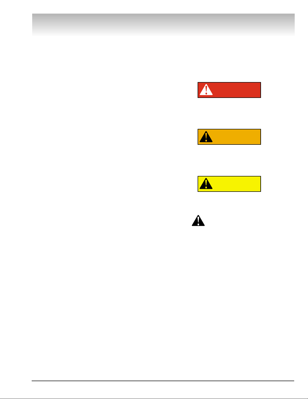
DANGER
Watch for this symbol:
It Means: Immediate hazards, which will result in
severe personal injury or death.
WARNING
Watch for this symbol:
It Means: Hazards or unsafe practices, which could
result in severe personal injury or death.
CAUTION
Watch for this symbol:
It Means: Hazards or unsafe practices, which may
result in minor personal injury or product or property
damage.
Watch for this symbol! It means BE ALERT! Your
safety, or the safety of others, is involved!
Safety
DANGER
WARNING
CAUTION
Page 6

vi • COATS 1001 Wheel Balancer
Safety
IMPORTANT SAFETY INSTRUCTIONS
SAVE THESE INSTRUCTIONS
READ ALL INSTRUCTIONS
1. Eye and face protection recommendations:
“Protective eye and face equipment is required to
be used where there is a reasonable probability of
injury that can be prevented by the use of such
equipment.” O.S.H.A. 1910.133(a) Protective goggles, safety glasses, or a face shield must be provided by the owner and worn by the operator of
the equipment. Care should be taken to see that
all eye and face safety precautions are followed by
the operator. ALWAYS WEAR SAFETY GLASSES.
Everyday glasses only have impact resistant
lenses, they are not safety glasses.
2. Do not disable hood safety interlock system, or in
any way shortcut safety controls and operations.
3. Be sure that wheels are mounted properly, the
hub nut engages the arbor for not less than four
(4) turns, and the hub nut is firmly tightened
before spinning the wheel.
4. Read and understand this manual before operating. Abuse and misuse will shorten the functional
life.
5. Be sure the balancer is properly connected to the
power supply and electrically grounded.
6. Do not operate equipment with a damaged cord
or if the equipment has been dropped or damaged
– until it has been examined by a qualified serviceman.
7. Do not let cord hang over edge of table, bench, or
counter or come in contact with hot manifolds or
moving fan blades.
8. If an extension cord is necessary, a cord with a
current rating equal to or more than that of the
equipment should be used. Cords rated for less
current than the equipment may overheat. Care
should be taken to arrange the cord so that it will
not be tripped over or pulled.
9. Keep guards and safety features in place and in
working order.
10. Wear proper clothing. Safety toe, non-slip
footwear and protective hair covering to contain
hair is recommended. Do not wear jewelry, loose
clothing, neckties, or gloves when operating the
balancer.
11. Keep work area clean and well lighted. Cluttered
and/or dark areas invite accidents.
12. Avoid dangerous environments. Do not use power
tools or electrical equipment in damp or wet locations, or expose them to rain.
13. Avoid unintentional starting. Be sure the balancer
is turned off before servicing.
14. Disconnect the balancer before servicing.
15. Use only manufacturer’s recommended accessories. Improper accessories may result in personal injury or property damage.
16. Repair or replace any part that is damaged or worn
and that may cause unsafe balancer operation. Do
not operate damaged equipment until it has been
examined by a qualified service technician.
17. Never overload or stand on the balancer.
18. Do not allow untrained persons to operate
machinery.
19. To reduce the risk of fire, do not operate equipment in the vicinity of open containers or flammable liquids (gasoline).
20. Adequate ventilation should be provided when
working on operating internal combustion
engines.
21. Keep hair, loose clothing, fingers, and all parts of
body away from moving parts.
22. Use equipment only as described in this manual.
23. Use only manufacturer’s recommended attachments.
Page 7

COATS 1001 Wheel Balancer • 1
Direct Drive
Specifications
• 5/16 Allen Wrench
• Single spin dynamic/static, twin plane.
• Vertical wheel mounting.
• Backcone and light truck cone mounting systems
standard.
• Accuracy ± 0.1 ounce (or ± 3 gram).
• Exclusive direct drive system (no belt - no pulleys).
• Forced air cooling.
• Cycle time - 4 1/2 seconds (standard tire).
• Rim diameter 10-17 inches.
• Fully interlocked guard hood (safety feature).
• Maximum tire diameter 42 inches.
• Shipping Weight 650 lbs.
• Fewest moving parts of any balancer.
• Large dials for data entry.
• “No bolt down” installation.
• Static/mag feature.
• Large readout in 1/4 ounce or 1/10 ounce or gram
increments.
• Greater distance from shaft to machine (better for
front wheel drive application).
• 1 1/2 H.P. modified torque motor:
Large housing for heat dissipation.
Motor insulation - heavy duty for high tem-
perature application.
Motor rated for 900 RPM use.
• Oversized weight bins.
• Standard adapters fit.
• ABS hood.
• Removable shaft for closed-center wheels.
• Control panel positioned for best visibility.
• Easy to read position lights.
• Scratch resistance surface.
• On-Off switch.
• Electronics isolated from motor heat.
• Simple calibration.
• Automatic rim gauge return.
• Strategically numbered dials for easy reading.
• 6-12-24 month guarantee.
Power Requirements
Standard: Optional: (Factory Installed)
220 VAC 115 VAC 220 VAC
20 AMPS 20 AMPS 20 AMPS
60 Hz 60 Hz 60 Hz
3 Phase 1 Phase 1 Phase
Standard Package
Includes balancer with built-in 17 bin weight tray,
interlocked guard hood, passenger car backcone
mounting system and light truck cone, 6 accessory
pegs, instruction manual, wheel weight tool and
calipers.
Page 8
2 • COATS 1001 Wheel Balancer
Direct Drive
Installation and Setup
A factory trained COATS®Service Technician must
perform the install, setup, and initial test procedures
on your 6401 balancer. Do not attempt to install and
setup the unit yourself. Accurate and reliable operation
of your unit depends on proper installation. Please
contact COATS®directly at 1-800-688-9240 for the
Certified Service Partner nearest you.
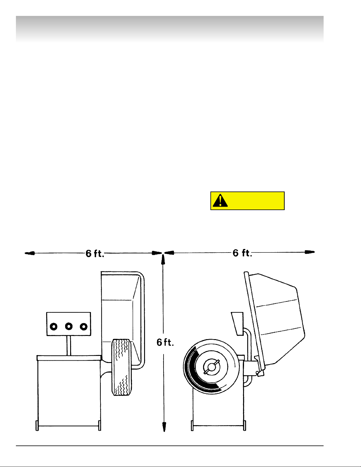
Floor and Space Requirements
The balancer must be located on a flat floor of solid
construction, preferably concrete. The balancer must
sit solidly on its three feet. If the balancer is not level,
does not sit solidly on its three feet, or is placed on an
unstable floor, the balancer will not function properly
and will produce inaccurate balance readings.
Do not operate the balancer when it is still bolted
down or while it is on the pallet.
Select a location for the balancer that provides a
level, solid floor, and adequate clearance around and
above the balancer. Make sure the location selected
has enough room above and behind the unit so the
hood can be raised completely. The location must also
provide working room for mounting and removing
wheels.
Unpacking
Check carton and pallet for crushed corners, broken
slats, gouges, and punctures which may indicate hidden damage. Make a note of all external damage on
the receiving waybill. Freight damage is the responsibility of the delivering carrier.
Initial testing and training are provided by our
COATS®distributor.
Remove outer carton from pallet. Remove strapping
holding hood in shipping position. Locate and remove
accessories. Notify manufacturers representative of
any missing accessories that were ordered.
Perform HOOD AND POD SET-UP.
Remove the single lag bolt and loosen the two (2)
anchor bolts holding the balancer to the pallet. Locate
and install the top two (2) accessory pegs. Carefully
slide the balancer off the pallet and move to final location.
Do not use the control pod, control pod
arm, faceplate, hood or stub shaft to lift the
balancer.
CAUTION
Page 9

COATS 1001 Wheel Balancer • 3
Install and tighten the four (4) remaining accessory pegs and
hang the accessories.
Note: Balancer will not operate properly on pallet.
Hood and Pod Set-up
To set up hood: Locate hood stop in accessory box and install
as shown. Install hood spring as shown. Do not install hood
spring until Control Pod has been set up.
Control Pod Setup: Carefully hold control Pod and Post while
removing 4 retaining screws. Swing Pod upright as shown
above and tightly reinstall the 4 screws. Now attach hood spring
from hood bar pin to base.
Note: Certain models will have the control pod already in its
operating position when received.
DO NOT drop Control Pod when removing the 4
screws.
Direct Drive
CAUTION
Page 10

Electrical Power
Consult a licensed electrical contractor for proper installation
to local electrical codes. Power outlets must be enclosed in a
floor raceway or overhead drop if predestrian or equipment traffic can damage existing power cord.
Operation with a defective ground circuit will create
a shock hazard for the operator and could damage
the balancers electronics. Operation with a defective
ground circuit may void warranty.
Precautions
Check voltage requirements on balancer ID plate. Balancer
requires nominal 220VAC, 60 Hz, three-phase power with a 20ampere fuse or circuit breaker. Mating outlet (not furnished) is
Hubbel 2420 or Bryant 71520, connected as shown below. A
factory installed option is available allowing operation from 115
VAC, single-phase power. A 20 ampere fuse or circuit breaker
and a standard three-pin safety outlet wired as shown below is
required. Electric outlets must have a solid connection (less
than one ohm between ground and pin and building ground).
Voltage Reading Between: 220V Type
X - Y 200 - 250
X - Z 200 - 250
X - Z 200 - 250
Voltage Reading Between: 220V Type
A - B 105 - 130
Power and ground requirements must be verified by installer
or inspector before connecting balancer. Failure to observe this
precaution may void warranty.
If balancer is bolted down, a licensed electrical contractor
must be consulted. Most electrical codes require “hard” wiring
when balancer Is bolted down.
Consult a licensed electrical contractor for proper installation
to local electrical codes. Power outlets must be enclosed in a
floor raceway or overhead drop if pedestrian or equipment traffic can damage existing power cord.
Direct Drive
4 • COATS 1001 Wheel Balancer
White
Black
Red
Green
Ground
To Outlet
X
Y
Z
White
Black
Green
To Outlet
Ground
CAUTION
Page 11

Initial Testing
Initial testing and training are provided by your COATS distributor. Complete instructions for unpacking and installIng your balancer are contained in the INSTALLATION AND SETUP section
of this manual.
Precautions: Initial testing should be performed by instructor.
Power requirements must be verified by installer or instructor
before connecting balancer. Failure to observe this precaution
may void warranty.
Power: Plug power cable into power outlet receptacle. Set circuit breaker in building breaker panel ON. Set ON-OFF switch
ON. Leave power on during working day.
Cooling Air: Check to verily cooling air blower is running. Do
not operate Unit unless cooling air flow is present.
Spin: (Standard 220 VAC 3-phase units.) Press START button
with hood down. Faceplate should rotate clockwise. If initial
direction of faceplate rotation is incorrect, set ON-OFF switch
OFF. Set building circuit breaker OFF. Interchange X-Y wires in
outlet plug. Set building circuit breaker ON, set ON-OFF switch
ON. Press START button. Faceplate initial rotation should be
clockwise when facing faceplate.
Spin: (Alternate 115 VAC single-phase Units.) Press START button with hood down. Faceplate should rotate clockwise for an
Interval and then stop.
If the above conditions cannot be obtained during initial test,
call the distributor for service advice.
New Features of (C) 1985 Microprocessor
1. “HUB” error message if wheel comes loose or no wheel.
2. “rr” error message if wheel goes up to speed in reverse
direction.
3. Display dims after 3 minutes if wheel is stationary.
4. “HI-ACC” active only when button held down. Initiated by
static and mag or by pushing start button 3 times.
5. Duty cycle display more accurate.
For all 1001 boards with S/N greater than 506625.
Direct Drive
COATS 1001 Wheel Balancer • 5
Page 12
6 • COATS 1001 Wheel Balancer
Direct Drive
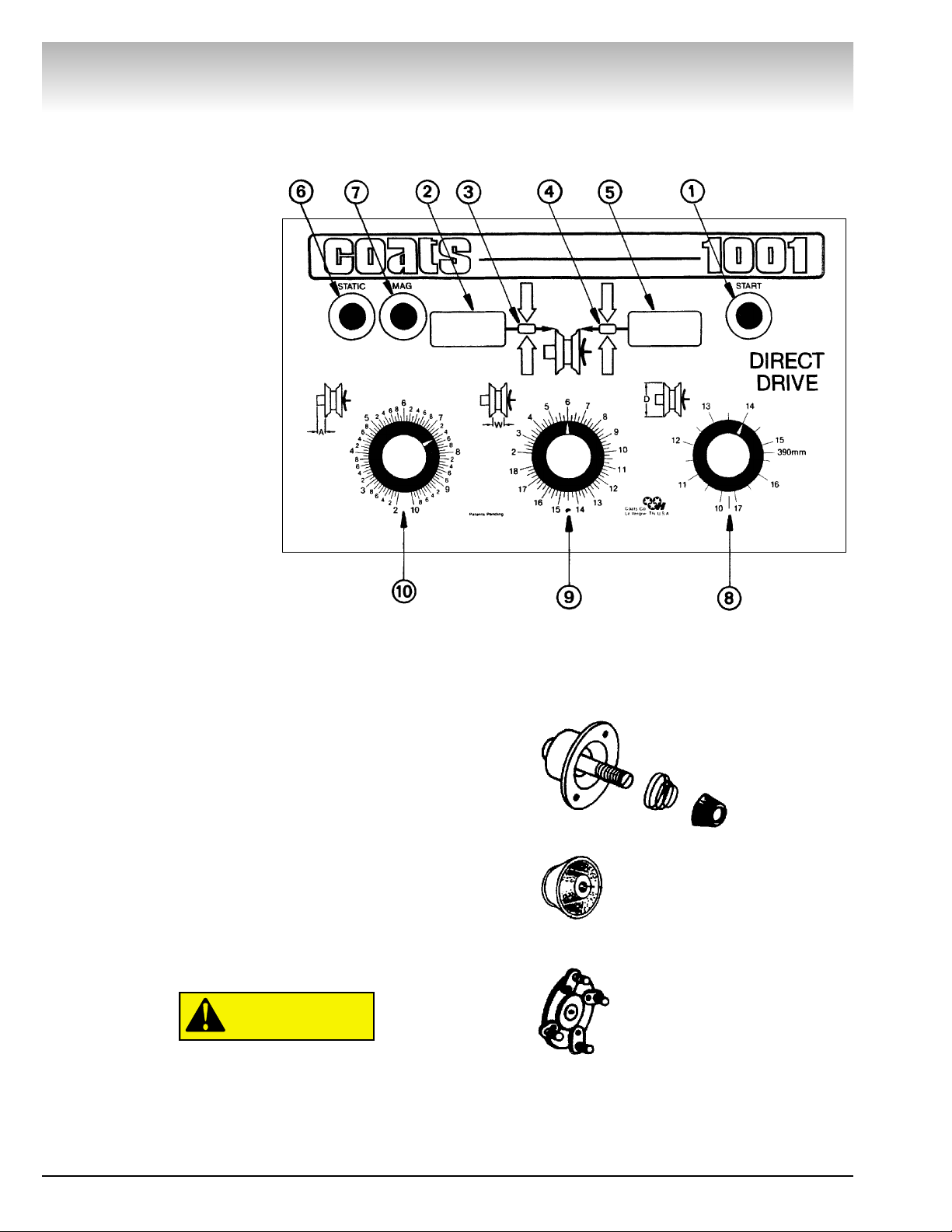
1. Start button
2. INNER weight display.
3. INNER position display.
4. OUTER position display.
5. OUTER weight display.
6. STATIC balance button.
7. “MAG” balance button.
8. Wheel diameter (D) knob.
9. Wheel width (W) knob.
10. Wheel offset (A) knob.
Balancing Procedure
Display Board Layout
Leave balancer power on all day.
Static power use is approximately 70 watts.
1. Mount Wheel
Select proper adapter. Adapter selected should center wheel
the same as the wheel is centered on the vehicle.
Almost all wheels, including aftermarket or “mag” wheels,
can be mounted using the standard back-cone mounting kit.
Light truck wheels can be mounted using The standard light
truck cone. Aftermarket wheels with larger than OE center
holes can be mounted using lug adapters.
Wheels that center off the lug pattern, i.e., 68 and older VW,
Peugeot, etc., can be mounted using the optional lug adapter.
The hubnut or lug nut threads must engage four full
turns. Rotate wheel while tightening to ensure centering. Failure to tighten hubnut securely may result
in serious personal injury.
CAUTION
Page 13
COATS 1001 Wheel Balancer • 7
Direct Drive
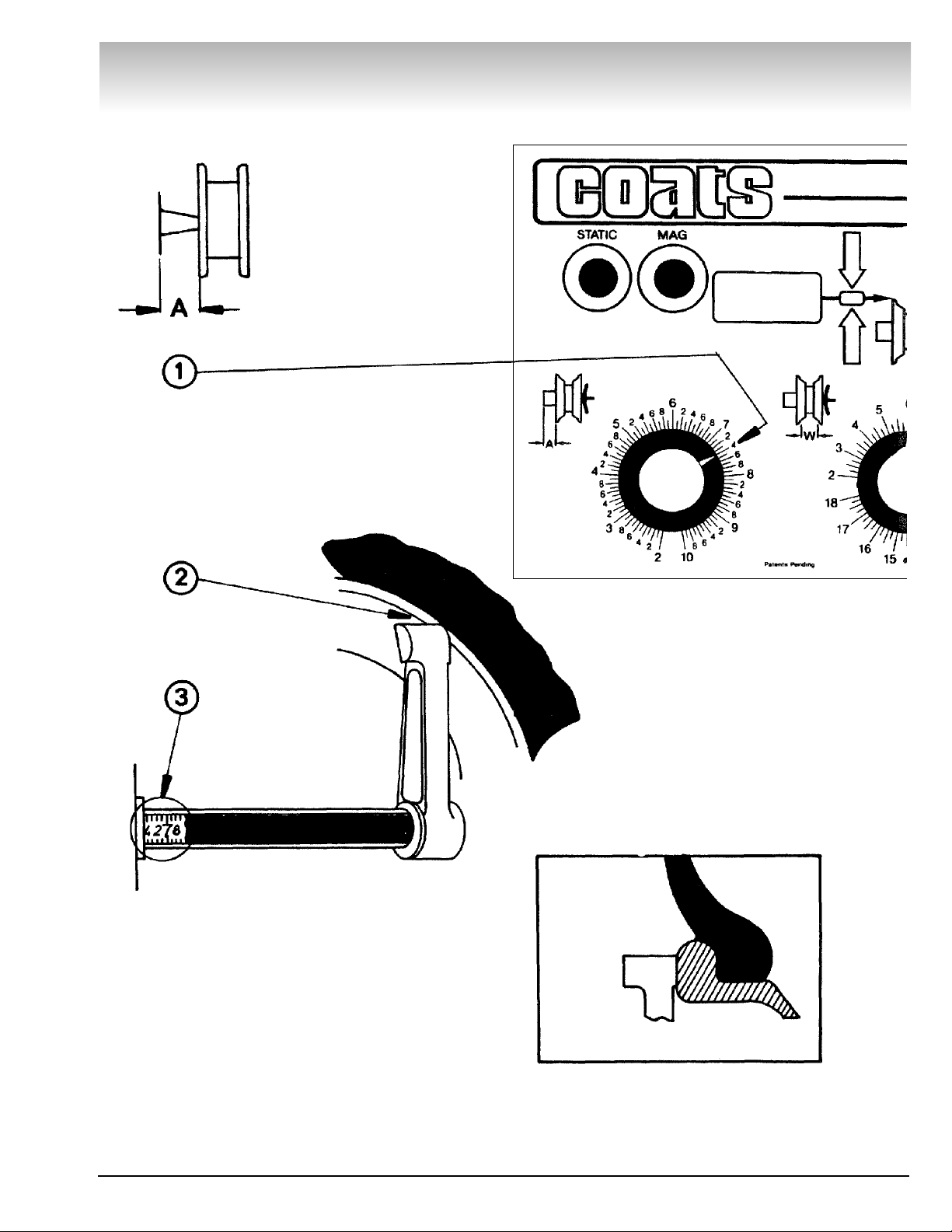
2. Offset
Enter offset distance with this knob.
Move distance gauge to
touch edge of wheel.
Setup for hidden weights on “mag”
is the same as for standard wheels.
Enter this distance
measurement with offset (A) knob. (Shown
in Fig. 1).
MAG Wheels
Page 14

8 • COATS 1001 Wheel Balancer
Direct Drive
3. Rim Width
Enter wheel width information
with this knob.
Use rim width calipers to
measure wheel at points
shown.
MAG Wheels
Setup for hidden weights on “mag” wheels
is the same as for standard wheels.
Enter this width reading
with the width (W) knob.
(Shown in Fig. 1).
Page 15

COATS 1001 Wheel Balancer • 9
Direct Drive
4. Rim Diameter
Enter rim diameter size as
read from tire sidewall.
Setup for hidden weights on
“mag” wheels is the same as
for standard wheels.
Enter this diameter reading
with the diameter (D) knob.
(Shown in Fig. 1).
Page 16

10 • COATS 1001 Wheel Balancer
Direct Drive
5. Spin Mode
Lower Guard Hood Before Starting Spin.
Press start button to obtain normal readings. Balancer will spin
and stop automatically.
6.Take Readings
Weight and position readings will appear on displays as balancer is braking tire.
FINE BALANCE (for unbalance of 0.2 ounce or less): hold
button down during spin cycle. Position readings will always
appear. (Not needed in normal use.)
7. Attach Weight
1. Rotate wheel until right (OUTER) twin lights blink alter-
nately.
2. Attach a weight equal to outer weight reading to outer rim
at top dead center. (See #2)
3. Rotate wheel until left (INNER) twin lights blink alternately.
4. Attach a weight equal to inner weight reading to inner rim at
top dead center. (See #4)
Note: The more accurate you are in
selecting the exact weight and position,
the more often you will balance in one
spin. Respin after applying weights to
obtain 0.00 reading.
CAUTION
Page 17

COATS 1001 Wheel Balancer • 11
Direct Drive
Balancing Special MAG
Wheels (Adhesive
Weights)
If standard clip weights are to be used, balance as a
“standard” wheel. The mag button is used when some
specialty wheels are to be balanced or when adhesive
weights are required (i.e., hidden weight method).
Note: Some specialty wheels do not require the hidden weight method of balancing. See example 2. If
adhesive weights must be used, follow these instructions.
See examples 1, 2 and 3 and select how weights will
be applied.
Set distance gauge, wheel width, and wheel diameter
as indicated in the proper example.
Lower hood and push appropriate button.
Read weight amount and locate position as with a
“standard” wheel.
Raise hood. Apply required weights.
Lower hood. Push appropriate button and check
weight application.
Note: Since hiding adhesive weights involves approx-
imations to actual wheel width and wheel diameter,
additional spins may be required. Simply respin and
apply weights as called for.
Be sure wheel surfaces are clean as per
adhesive weight manufacturer’s recommendations. Apply weight securely, failure to do
so may cause weights to come loose resulting in serious personal injury.
START
Note: The mag button is
not used for this method
of balancing.
Since rim diameter is slightly
smaller than tire size “D”, enter
one inch smaller than tire size.
Move distance gauge arm to
here, and enter distance
gauge reading.
Measure rim width “W” with
rim width calipers and enter
this measurement.
OUTER adhesive
weight will be
applied here.
Read OUTER weight amount
and locate position for outer
plane. Install weights as
described above.
Read INNER weight amount
and locate position for Inner
plane. Install weights as
described above.
INNER adhesive
weight will be
applied here.
Note: Be sure adhesive weights will clear disc brake calipers.
1. Two Adhesive Weights
(Outside Weight Visible)
WARNING
Page 18

Direct Drive
12 • COATS 1001 Wheel Balancer
MAG
Use Mag Button.
Enter rim diameter as read
from the sidewall.
Move distance gauge arm to
touch inner edge of wheel.
Enter distance gauge reading.
Read INNER weight amount
and locate position for inner
plane. Standard clip weight
will be placed here.
OUTER adhesive weight
will be applied here.
Read OUTER weight amount and
locate position for outer plane, Install
weight as described on page above.
Measure rim width “W”
with rim width calipers and
enter this measurement.
Note: Be sure adhesive weights will clear disc brake calipers.
MAG
Use Mag Button.
Enter rim diameter as read
from the sidewall.
OUTER adhesive
weight will be
applied here.
INNER adhesive
weight will be
applied here.
Note: Be sure adhesive weights will clear disc brake calipers.
3. Two Adhesive Weights
(Hidden Method)
2. Standard Clip Weight One Adhesive Weight
(Hidden Method)
Move distance gauge arm
to here and enter distance
gauge readings.
Read INNER weight amount
and locate position for inner
plane. Install weight as
described on page above.
Measure rim width “W”
with rim width calipers and
enter this measurement.
Read OUTER weight amount
and locate position for outer
plane. Install weight as
described on above.
Page 19

Direct Drive
COATS 1001 Wheel Balancer • 13
Note: This method should only be used when the customer requests no visible
weights (outer plane) and there is a caliper clearance problem on the inner plane.
Since rim diameter is slightly
smaller than tire size “D” enter
one inch smaller than tire size.
Note: Since Static balancing is not as
good as twin-plane (Dynamic/Static)
balancing, the offset (A) and width
(W) knobs do not have to be set.
Adhesive weight will be
applied here.
Read INNER weight amount
and locate position for static
imbalance. Install weight as
described on above.
Note: Be sure adhesive weights will clear disc brake calipers.
Static Balancing
(Adhesive Weight)
STATIC
Use Static Button.
Page 20

Wheel Mounting Options
Back Cone Mounting
1. Place spring over threaded stud with the large end
inside of the faceplate.
2. Select a cone that best fits into wheel center hole.
3. Slide selected cone onto threaded shaft with the
large end against the spring.
4. Lift wheel onto shaft and center on cone.
Cone centers wheel—Cone must be centered in wheel center hole before tightening.
The wheel must be forced firmly against the
faceplate. Thread hubnut on and tighten by
rotating wheel and striking both arms of
hubnut with palm of hand. Hubnut must
engage threads for at least four full turns.
Failure to tighten hubnut securely may result
in serious personal injury.
Light Truck Cone
Cone must be centered in wheel center hole
before tightening. Thread hubnut on and
tighten by rotating wheel and striking both
arms of hubnut with palm of hand.
Hubnut must engage threads for at least
four full turns. Reverse hubnut when necessary. Hubnut and cone must force wheel
firmly against faceplate. Failure to tighten
hubnut securely may result in serious personal injury.
Direct Drive
14 • COATS 1001 Wheel Balancer
CAUTION
CAUTION
CAUTION
CAUTION
Page 21

COATS 1001 Wheel Balancer • 15
Special Problems
Customers will occasionally complain of vibration on
the car after balancing. Some possible causes are
listed below:
1. Beads improperly seated. Check bead seating and
inflation pressure before balancing spin.
2. Stiffness variations in radial belts.
3. Tire out of round; wheel out of round, bent, or not
running true. Visually check runout of wheel and tire
during balance spin. Re-check mounting. Replace
wheel or tire if necessary.
4. Suspension wear, misalignment, or loose vehicle
components.
5. Wheels not correctly centered due to damaged
hub, damaged or worn center hole, worn bolt circle
holes, or imprecise original design. Check wheel run
out before balance spin and on the vehicle after mounting.
6. Sensitive suspensions. Use FINE BALANCE (See
page 10).
Complaint: Balancer uses too many weights or several spins to balance.
Remedy: Recheck rim dimensions entered. Position
the weights exactly top dead center when green position lights are on.
Complaint: Weight or position readings fluctuate.
Remedy: Check cone/hubnut for slippage. Check that
the balancer is resting firmly on three mounting points,
floor is flat and stable, and that no tools or weights are
between balancer and floor.
Calibration
Calibration Check Procedure
The calibration check procedure can be performed by
the operator to ensure that the balancer is operating
correctly and is properly calibrated. The only purpose of
calibration is to trim the balancer to yield single-spin
balancing.
Note: If the balancer is set up to display weights in
grams instead of ounces, then observe the parenthesis (0.00 gram) values in the CALIBRATION CHECK
PROCEDURE and the CALIBRATION ADJUSTMENT
MODE.
Throughout the calibration, check procedure, keep
the start button depressed during each cycle. This is
the FINE BALANCE mode which allows the balancer to
read in .01 ounce (1 gram) increments.
1. Mount a standard domestic 14" x 6" wheel with an
F78-14 or 206/75-14 tire using the proper back cone.
Ensure that the wheel is not bent or misaligned and
that the center hole is free of nicks and burrs.
2. Program the distance, rim width, and rim diame-
ter information into the balancer by setting the knobs
on the front panel.
3. Balance the wheel using FINE BALANCE until
0.00 weight readings appear on INNER and OUTER
displays while holding down the start button during the
entire cycle.
4. After getting 0.00 to appear while holding the
start button, change the Rim Diameter adjustment to
read 10.5. If any weight reading appears, repeat step 3.
5. Return the Rim Diameter adjustment to 14.
6. Install a 4 ounce (113 gram) test weight on the
outer rim.
7. Spin. The new weight reading should be 3.80 to
4.20 ounce (108 gram to 119 gram). Rotate the wheel
so that the central position lights on the outer position
indicator come on. The test weight should be directly
across (at 6 o’clock).
Weight readings on the inner display should be 0.20
ounce (6 gram) or less. (This results from interference
between the two balancing planes.)
8. Repeat steps 6 and 7 with the 4 ounce (113 gram)
test weight on the inner rim.
9. If the balancer fails to yield the results required by
this procedure, perform the CALIBRATION ADJUSTMENT PROCEDURE.
Direct Drive
Page 22

16 • COATS 1001 Wheel Balancer
Direct Drive
Calibration Adjustment Procedure
Note: Do not preform Calibration Adjustment when
motor is excessively hot.
1. Perform the calibration check procedure steps
one (1) through seven (7) (See Page 15).
2. Remove the four (4) screws holding the control
panel shroud and lift the shroud off.
3. Place an 8 ounce (226 gram) test weight on outer
rim of wheel.
4. Set service switch to upper position (test mode).
Press the START button. The display will now read
“TEST”. The outer and inner position lights will now act
as bar graphs. First adjust the gain trimpot until the
minimum number of lights are on or flashing.
Alternately adjust the gain and phase trimpots until all
the lights are off.
5. Set service switch to bottom position (NORM).
Remove the test weight and then balance the wheel.
A maximum imbalance of .07 ounce (2 gram) on the
inner and outer weight displays is allowed.
6. Place a 4 ounce (113 gram) test weight on the
outer rim.
7. Set the service switch to center position (non-
stop). Press the START button. Wheel will come up to
speed, but not go into braking mode. Now adjust the
outer weight trimpot (affects outer magnitude). After
each adjustment of the trimpot, press and hold the
START button until a new reading appears on the display. Continue this procedure until the outer weight
display reads 4 ounce (113 gram). The inner weight
reading should be .21 ounce (6 gram) or less. Set the
service, switch to the bottom position so that the
wheel will brake to a stop.
8. Place the 4 ounce (113 gram) test weight on the
inner rim. Set service switch to center position. Press
the START button.
9. Adjust the inner weight trimpot (affects inner
magnitude) until display reads 4 ounce (113 gram). Use
the same procedure as in Step 7. The outer weight
reading should be .21 ounce (6 gram) or less. Set the
service switch to the bottom position (NORM).
10. Calibration is now complete. To return the bal-
ancer to the normal operating mode: Switch off the
power and then turn it on again (On/Off switch located
on rear of machine). This clears the high accuracy
mode and the balancer is ready to use.
Optional Combi Adaptor
Combi adapter may be used for 3, 4, 5, 6, 8, or 10Lug wheels by installing swivel plates in Combi plate
hole pattern. Set up adapter as follows:
Install a swivel plate in combi plate “common” hole.
Line up number gear to match “345” mark with index
mark on swivel plate. Insert swivel plate bolt through
back of combi plate and run up. DO NOT TIGHTEN.
Note: This swivel plate is used for all bolt circle patterns.
Install proper number of swivel plates in combi plate
holes marked “3”, “4”, or “5” as required. Insert swivel
plate bolts through back of combi plate and run up, DO
NOT TIGHTEN. Ensure that index marks on all swivel
plates line up with the appropriate “3”, “4”, or “5” mark
on the number gear.
Install combi adapter on wheel Run up lug nuts by
hand. Tighten lug nuts with adapter wrench, using a
star or criss-cross pattern.
Lug nuts must be centered and threaded at
least four full turns Reverse lug nuts as
required. Use only adapter wrench furnished with adapter Do not use air tools or
impact wrenches.
Tighten swivel plate bolts with alien wrench.
Attach wheel and adapter to faceplate with two
faceplate nuts.
Faceplate nuts must be hand tightened.
Rotate wheel while tightening to ensure
centering.
Adapter should remain on faceplate for additional
wheels with same bolt circle.
High Accuracy Mode For Calibration
CAUTION
CAUTION
Page 23

COATS 1001 Wheel Balancer • 17
Optional Combi Adapter
Direct Drive
Preventative
Maintenance
DO NOT use a solvent which leaves an oil
residue.
NEVER use compressed air or a water hose
to clean any part of your balancer.
Daily: Clean shaft and faceplate with a vaporizing sol-
vent. Cones, hubnut and other mounting hardware
should be checked/cleaned at this time.
Monthly: Clean entire machine. Remove all used
weights, tools and parts which may be under, or leaning against balancer. Perform Calibration Check
Procedure. Make adjustments only if required.
Yearly: Have your COATS authorized service person-
nel perform the following: Clean Optical Sensor, Clean
Fan Motor Air Inlet.
CAUTION
CAUTION
Page 24

8143259 01/01 rev. 2 © Copyright 1993, 2001 Hennessy Industries and COATS All Rights Reserved Printed in USA
 Loading...