

Page 1
MODEL L-1C
FAX 714-895-2141
CMA DISHMACHINES
PARTS MANUAL
Rev 1.00
12700 KNOTT AVENUE
GARDEN GROVE, CALIFORNIA 92841
800- 854- 6417
www.cmadishmachines.com
Page 2

TABLE OF CONTENTS
MODEL CMA-L-1C
1. PARTS MANUAL .......................................................................................... 3
1.1. INITIAL PARTS KIT (P/N 4001.50) ................................................................................................... 3
1.2. OPTIONAL SANI ALARM .................................................................................................................. 4
1.3. EXPLODED VIEW DRAWINGS ........................................................................................................... 5
1.3.1. Cabinet Assembly ................................................................................................................... 5
1.3.2. L-1C Door Assemb l y .............................................................................................................. 6
1.3.3. Spray System Assembly ........................................................................................................... 7
1.3.4. S/S Pump Assembly ................................................................................................................. 8
1.3.5. Plumbing System Assembly ..................................................................................................... 9
1.3.6. Drain System Assembly..........................................................................................................10
1.3.7. Control Panel ........................................................................................................................11
1.3.8. Electrical Panel .....................................................................................................................12
1.3.9. Peristaltic Pump Assembly ....................................................................................................13
1.3.10. Drain Valve ...........................................................................................................................14
Page 3
Parts Manual
1. Parts Manual
1.1. Initial Parts Kit (P/N 4001.50)
P/N DESCRIPTION Qty
00120.02 Bi Metal Thermometer 1.5” 1
00200.75 Pump Assy, 110/220V 60 Hz, Open 1
00206.70 Pump Seal Kit 1
00208.40 Slip Joint Nut Gasket 1
00304.04 Spray Arm Short B- L1X-L1X16 1
00308.50 Spray Arm End Plug SS 1
00404.82 Motor Contactor Relay 1
00411.00 Micro Switch 1
00415.00 Peristaltic Pump Assembly, 120V/60Hz 1
00425.51 Chemical Tubing Blue 50 ft.
00425.53 Chemical Tubing Red 50 ft.
00471.10 Toggle Switch DPST 20 Amp 1
00501.00 Timer Motor, 2-Minute 1
00715.00 1/2 Ball Check Valve 1
02257.00 Squeeze Tube 8" Norprene 1
02257.22 Squeeze Tube 22" Norprene For L-1X 1
03406.64 Drain Toggle Switch 1
03415.00 Chemical Tube Bulkhead 1
03415.60 Chemical Bulkhead Assy.(Teflon) 1
03470.01 Toggle Switch(Moment) .25 Flat Term 1
03604.30 Dema Valve Repair Kit 1/2" 1
04103.00 L-1C Drain Valve, 120V 1
04110.00 SS L1-C Drain Screen 1
04113.00 Drain Valve 115V New style 1
04303.00 Spray Arm Bearing (L1X/GLX) 1
04517.15 Door Stop Undercounter (Parallel) 1
NOTE: CMA recommends that the initial parts kit be kept on hand as a back up supply of critical parts
in the event your machine should require emergency service. All the parts included in this kit
are unique to the L-1C dishmachin e.
MODEL L-1C PARTS MANUAL Rev. 1.17A Page
3
Page 4
Parts Manual
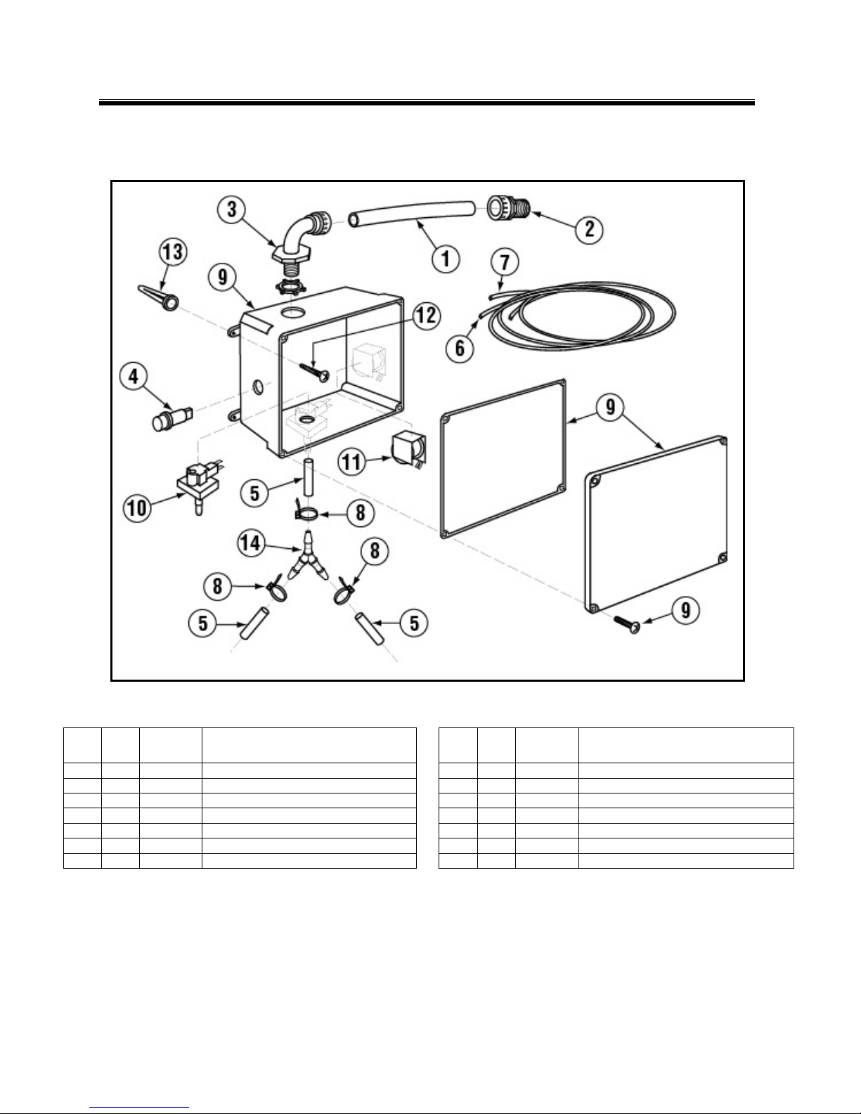
1 3 00400.00
Conduit, 3/8” Sealtite
8 5 00931.00
Wire Tie, Small
3 1 00402.00
S.T. 90 Degree 3/8” Connector
10 1 12511.50
Sanitizer Low Level Vacuum Switch
4 1 00406.00
Control Box Light, .5” Diameter, Red
11 1 12512.00
Sanitizer Alarm Buzzer, 120 Volts
6
AR
00521.00
Wire, 18 Gauge, Orange, 6 ft.
13 4 40127.00
Wall Anchors
7 1 00531.00
Wire, 18 Gauge, White, 6 ft.
14 1 00426.00
Y Hose Connector, 3/16”
1.2. Optional Sani Alarm
Part Number 12508.00
Exploded View
ITEM
NO.
NO.
REQ’D
2 1 00401.00 S.T. 3/8” Straight Connector 9 1 12510.00 Sanitizer Alarm Box Assembly
5 1 00435.00 Squeeze Tube, 8” 12 4 40126.10 #10 x 3/4" Sheet metal Screw
P/N DESCRIPTION
MODEL L-1C PARTS MANUAL Rev. 1.00 Page
ITEM
NO.
NO.
REQ’D
P/N DESCRIPTION
4
Page 5

Parts Manual
1.3. Exploded View Drawings
1.3.1. Cabinet Assembly
ITEM
MODEL L-1C PARTS MANUAL Rev. 1.00 Page
NO.
NO.
REQ’D
1 1 05903.00 Energy Mizer L-1C Wrapper 5 4 05933.00 Energy Mizer L-1C Feet
2 1 05901.00 Energy Mizer L-1C Body 6 1 05904.00 Energy Mizer L-1C Front Panel
3 1 00556.10 Reed Switch 7 1 00120.01 BiMetal Thermometer
4 1 5902.00 Energy Mizer L-1C Base
P/N DESCRIPTION
ITEM
NO.
NO.
REQ’D
P/N DESCRIPTION
5
Page 6

1.3.2. L-1C Door Assembly
Parts Manual
ITEM
NO.
NO.
REQ’D
1 1 05905.00 Energy Mizer L-1C Door 5 2 05932.00 Energy Mizer L-1C Door Spring
2 2 00940.50 10-32 X 3/8 Truss Head Screw 6 1 556.60 Reed Switch Magnet
3 1 05912.00 Energy Mizer L-1C Door Handle 7 1 00911.00 8-32 X 1/2 Panhead Screw
4 2 05913.00 Energy Mizer L-1C Door Spring
MODEL L-1C PARTS MANUAL Rev. 1.00 Page 6
P/N DESCRIPTION
Arm
ITEM
NO.
NO.
REQ’D
P/N DESCRIPTION
Page 7

Parts Manual
1.3.3. Spray System Assembly
ITEM
NO.
NO.
REQ’D
1 8 00912.00 1/4"-20 Nylon Lock Nut
2 16 00924.00 1/4" SS Washer
3 8 00929.00 1/4"-20 x 3/4" Truss Head Bolt
4 2 04306.00 Square Manifold Gasket
5 2 04305.10 Silicon Gasket
6 2 04303.00 L-1C Spray Arm Bearing
7 2 00304.04 Spray Arm
8 4 00308.50 Spray Arm End Plug
9 6 03101.00 Hose Clamp #16 1”
10 Ft 05939.50 L-1C Manifold Pipe SS
11 1 05936.00 Energy Mizer L-1C Tee 1"X1"X1"
12 1 13109.00 Drain Hose 90Deg 1”
13 2 05930.00 Energy Mizer L-1C Spray Base
14 2 03108.67 Transfer Hose 1" Reinforced 2"
15 2 03108.60 Transfer Hose 1" Reinforced
16 1 00307.10 Spray Arm Assy L1X/GL-X
MODEL L-1C PARTS MANUAL Rev. 1.00 Page 7
P/N DESCRIPTION
Page 8

Parts Manual
1.3.4. S/S Pump Assembly
ITEM
NO.
NO.
REQ’D
1 3 00908.00 5/16”-18 x 5/8” SS Hexhead Bolt 9 1 03222.70 SS Pump Impeller
2 3 00926.00 5/16” SS Washer 10 1 50302.10 1" MPT x 1" Barb Brass
3 1 00200.78 SS Pump Motor Holder "L" 11 1 04206.75 SS Pump Co ver
4 1 00201.75 SS Wash Pump Motor 115v 12 1 00214.50 1/ 2" Com p x 3/8” MIP Adapter
5 1 03224.72 Back Plate Spacer 13 1 00208.40 Sl i p Joint Nut O Ring Buna
6 1 03224.70 SS Pump Backpl ate 14 1 00207.00 Sl i p Joint Nut 1 1/2 x 1 1/4
7 1 03226.70 Volute O-Ring For SS Pump 15 1 00238.00 3/8” Male P l ug
8 1 00206.70 SS Pump Seal Kit 16 1 00200.75 Includes Items 4,5,6,7,8,9,and 11
MODEL L-1C PARTS MANUAL Rev. 1.00 Page 8
P/N DESCRIPTION
ITEM
NO.
NO.
REQ’D
P/N
DESCRIPTION
Page 9

Parts Manual
1.3.5. Plumbing System Assembly
ITEM
NO.
NO.
REQ’D
1 1 03623.00 1/2" Vac. Brkr Repair Kit – WATTS 17 1 00924.00 1/4" SS Washer
2 1 03624.00 1/2" Vacuum Breaker – WATTS 18 1 00725.50 1/2" Plumbing Strap
3 2 00721.00 1/2" Jamb Nut 19 1 00747.10 Nipple Brass 1/2" x 5”
4 2 00770.10 5/8 Compression Fitting Nut 20 1 03602.50 1/2" Y Strainer – Optional
5 1 00748.00 1/2" Sprinkler Head Assembly 21 1 41062.00 1/2 Strainer B all Valve
6 1 04605.00 L-1X “U” Tube 22 1 00739.50 Vacuum Breaker Cap SS
6A 1 04605.60 L-1X 16“U” Tube 23 1 03624.25 Vacuum Breaker Bonnet Brass
7 1 00715.00 Ball Check Valve 24 1 00743.12 Tee 1/ 2C x 1/2C x 1/2 Male
8 1 00798.00 SS Braided Hose 25 1 00742.00 Nipple Brass 1/2" x 1-1/2” (Optional)
9 1 00214.50 1/2" Comp x 3/8” MIP FTG 26 1 00744.00 Nipple Brass 1/2" x 2” (Optional)
10 4 00738.10 Water Solenoid Coil J/E 27 1 03603.20 1/ 2" Water Solenoid Bonnet
11 1 00707.00 1/2" Water Solenoid Repair Kit J/E 28 1 00786.00 Water Solenoid Valve Plunger
12 1 03603.10 1/2" Water Solenoid Valve J/E 29 1 41062.10 ^ 1/2 Ball Valve Strainer Only
13 1 00745.00 1/2" 90 Degree Street Elbow 30 2 00970.40 6-32 x 1/4" Phillips Pan Head Screw
14 6 00760.00 5/8” Comp. X 1/2" MIP Adapter 31 1 00706.10 Plunger Spring Only
15 1 04606.00 L-1X “L” Tube 32 2 00770.20
15A 1 04606.60 L-1X16 “L” Tube 33 1 14508.50
16 1 00915.00 1/4"-20 Hex Nut
P/N DESCRIPTION
ITEM
NO.
NO.
REQ’D
P/N DESCRIPTION
5/8 Compression Fitting Ring
Plumbing Support Bracket
MODEL L-1C PARTS MANUAL Rev. 1.00 Page
9
Page 10

Parts Manual
1.3.6. Drain System Assembly
ITEM
NO.
NO.
REQ’D
1 2 04105.00 Pump Hose 6.5”
2 8 03101.00 1” Hose Clamp #16
3 1 04103.00 L-1X Drain Valve (Depend-O-Drain)
4 1 03108.51 1” Goose Neck Drain Hose
5 1 03109.00 Drain Hose 90DEG 1"
6 1 04110.00 L-1X Drain Screen SS
7 1 50302.06 1” MIP x 1” Barb PVC
MODEL L-1C PARTS MANUAL Rev. 1.00 Page 10
P/N DESCRIPTION
Page 11

Parts Manual
1.3.7. Control Panel
ITEM
NO.
NO.
REQ’D
1 1 05960.00 L1C-NST Control Panel 6 4 03475.00 Toggle Switch DPDT 16A, 2 pos
2 2 03801.00 10-32 Lock Nut 7 4 03476.00 Rubber Boot
3 2 04806.00 #10 Brass Washer 8 1 00406.00 Control Box Light .5" D Red
4 1 03485.00 Switch Guard 9 1 06231.73 L1C-NST Panel Label (2013)
5 1 15524.00 Power Rocker Switch Red 115V
P/N DESCRIPTION
MODEL L-1C PARTS MANUAL Rev. 1.00 Page 11
ITEM
NO.
NO.
REQ’D
P/N DESCRIPTION
Page 12

Parts Manual
1.3.8. Electrical Panel
ITEM
MODEL L-1C PARTS MANUAL Rev. 1.00 Page 12
NO.
NO.
REQ’D
1 1 00404.82 Contactor Relay 8 1 00408.80 Timer 2 Minute 8 Cam
2 1 00631.00 Ice Cube Relay 8A 8 00411.00 Micro switch (not shown)
3 10 00916.00 6-32 PM Nut 8B 1 00501.00 Timer Motor (not shown)
4 2 01001.00 6-32 X 1 Phillips Panhead Screw 9 1 03408.50 Counter (Panel Mount – Small)
5 1 15520.50 Power Block 3 Position 10 1 00475.30 Delimer Switch DPDT 20A,2Pos.
6 8 00907.00 6-32 X 1/2 SS Panhead Screw 11 1 00470.00 T oggl e switch DPDT Momentary
7 1 05911.00 Energy Mizer L-1C Control Panel 12 2 00470.10 Rubber Boot
P/N DESCRIPTION
ITEM
NO.
NO.
REQ’D
P/N DESCRIPTION
Page 13

Parts Manual
1.3.9. Peristaltic Pump Assembly
ITEM
NO.
NO.
REQ’D
1 3 00416.00 Peristaltic Pump Motor G 3 00424.00 Rotor Bearing Carriage
2 3 00417.10 Peristaltic Pump Block (Black) H 3 00935.00 1/4"-20 x 1/4" Allen Screw
3 6 00919.00 10-32 x 1 1/2" Pan Head Screw 10 6 00448.00 Barrel Connector (Male)
4 3 00918.00 10-32 x 1 1/2" Fillister HD Screw 11 AR 00425.51 Chemical Tubing (Blue)
5 6 00932.00 Wire Tie – Large 12 AR 00425.53 Chemical Tubing (Red)
6 7 00418.00 Peristaltic Pump Block Cover 13 AR 00425.54 Chemical Tubing (White)
7 12 00911.00 8-32 x 1/2" Pan Head Screw 14 2 03415.00 Chemical Tube Bulkhead
8 2 00435.10 Squeeze Tube – Orange 8” 15 2 00443.00 Tube Sti ff ener
8A 1 00435.14 Squeeze Tube – Orange 22” 16* 1 00415.00 Complete Peristaltic Pump
9 3 00419.00 Peristaltic Rotor Assembl y 17 1 03415.20 Bulk Head For Sanitizer
E 6 00423.00 Rotor Bearing 18 1 00435.62 24” Squeeze Tube
F 6 00422.00 Rotor Bearing Pin
MODEL L-1C PARTS MANUAL Rev. 1.00 Page 13
P/N DESCRIPTION
ITEM
NO.
NO.
REQ’D
*Item 16 includes items 1-4, 6-10.
P/N DESCRIPTION
Page 14

Parts Manual
1.3.10. Drain Valve
ITEM
NO.
NO.
REQ’D
1 1 00104.50 Drain Motor 120V
2 1 04103.14 Drain Valve Spring
3 1 04103.20 Drain Valve Drive Pin
4 1 04103.19 Drain Valve Washer (Thin)
5 1 04103.17 Drain Valve Seal Washer (V-Packer)
5A 1 04103.23 Drain Seal Bearing (White Washer)
6 1 04103.13 Drain Valve Housing Cover
7 4 04113.18 Valve Cover Screw
8 3 04103.16 Drain Valve Hinge/Seal
9 1 04103.15 Drain Valve Housing Gasket
10 1 04113.12 Drain Valve Housing
11 1 04103.18 #8 X 5/8 Self Threading Screw
P/N DESCRIPTION
MODEL L-1C PARTS MANUAL Rev. 1.00 Page
14
 Loading...