


CMA-180UC
Table of contents
 Loading...
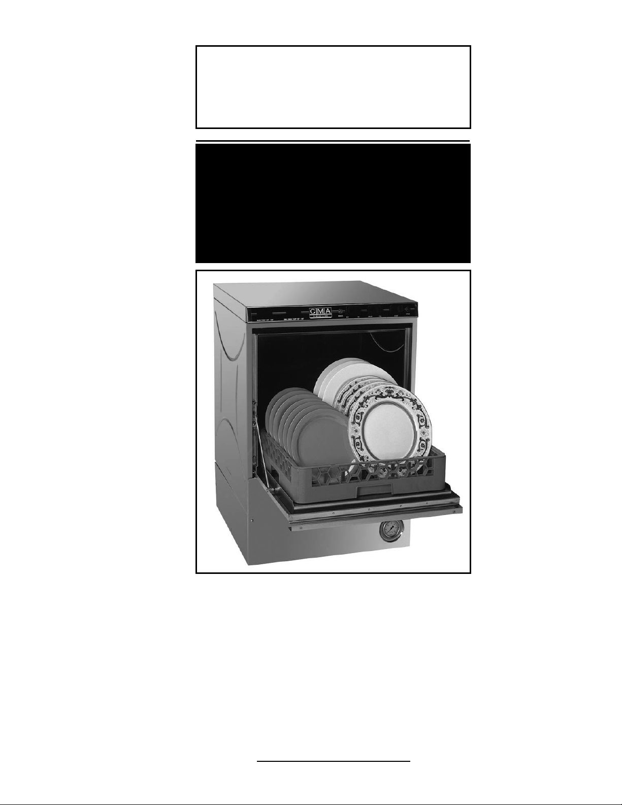
Owner’s Manual
Keep with machine for reference
MODEL CMA-180UC
INSTALLATION & OPERATION
Rev 1.15
CMA DISHMACHINES
12700 KNOTT AVENUE
GARDEN GROVE, CALIFORNIA 92841
800-854-6417
FAX 714-895-2141
www.cmadishmachines.com

TABLE OF CONTENTS
MODEL CMA-180UC
1. SPECIFICATIONS ........................................................................................ 2
1.1. CMA-180UC......................................................................................................................... 2
1.2. CMA-180UC OPERATIONAL CYCLE...................................................................................... 3
2. GETTING STARTED..................................................................................... 4
2.1. INTRODUCTION TO CMA-180UC........................................................................................... 4
2.2. RECEIVING AND INSTALLATION.............................................................................................. 5
2.2.1. Electrical ....................................................................................................................... 5
2.2.2. Plumbing........................................................................................................................5
2.2.3. NOVA Detergent and Rinse Dispenser (Optional)........................................................ 6
2.2.4. Safe Ttemp Feature........................................................................................................ 8
2.2.5. Water Tempering Kit ..................................................................................................... 9
2.2.6. Booster Heater Setup...................................................................................................10
2.2.7. Installers Checklist ...................................................................................................... 10
3. OPERATION............................................................................................... 11
3.1. INITIAL SETUP ...................................................................................................................... 11
3.1.1. Dema Valve and Dema Flow Disc (New Models)....................................................... 11
3.1.2. Rinse Pressure Regulator (Old Models Prior January 2008)......................................11
3.1.3. Rinse and Wash Temperatures .................................................................................... 11
3.1.4. Post Instructions.......................................................................................................... 11
3.2. STARTUP PROCEDURES......................................................................................................... 11
3.3. OPERATING AND CLEANING INSTRUCTIONS ......................................................................... 12
3.4. PREVENTIVE MAINTENANCE CHART .................................................................................... 13
3.5. QUICK SERVICE GUIDE.......................................................................................................... 14
3.6. TROUBLESHOOTING.............................................................................................................. 15
4. PARTS KIT ................................................................................................. 18
4.1. INITIAL PARTS KIT (P/N 1100.66)........................................................................................18
4.2. OPTIONAL DRAIN PUMP KIT................................................................................................. 19
4.3. OPTIONAL DRAIN PUMP—INSTALLATION INSTRUCTIONS.................................................... 20
5. CUSTOMER NOTICE ................................................................................. 22
6. ELECTRICAL DIAGRAM............................................................................ 23
www.cmadishmachines.com

1. Specifications
1.1. CMA-180UC
METRIC
EQUIVALENT
WATER CONSUMPTION
PER RACK .86 GAL. (3.25 L)
PER HOUR 20.6 GAL. (77.8 L)
OPERATING CYCLE
WASH TIME-SEC 94 94
RINSE TIME-SEC 16 16
DWELL TIME-SEC 10 10
TOTAL CYCLE 2 MIN. 2 MIN.
OPERATING CAPACITY
RACKS PER HOUR 30 30
WASH TANK CAPACITY 2.5 GAL. (9.46 L)
PUMP CAPACITY 38 GPM (144 LPM)
WATER REQUIREMENTS
140°F (60°C)
WATER INLET ½” 1.27cm
DRAIN CONNECTION 1” 2.54cm
RINSE PRESSURE SET
CYCLE TEMPERATURES
20 PSI±5 PSI
1.41 kg/cm
2
WASH-°F 150°F -160°F (65.5°C/71°C
RINSE-°F 180°F -195°F (82°C/90°C)
FRAME DIMENSIONS
DEPTH 25” (63.5 cm)
WIDTH 24” (60.96 cm)
HEIGHT 33 ¼” (84.45 cm)
MAX CLEARANCE FOR DISHES 14.5” (36.8 cm)
ELECTRICAL RATING*
208 VOLTS
1 PH—60 Hz
33 AMPS 35 AMPS
230 VOLTS
1 PH—60 Hz
BOOSTER HEATER 5.3 kW 6.5 kW
WASH PUMP MOTOR ¾ HP ¾ HP
THIS SYSTEM REQUIRES THREE POWER WIRES, WHICH
INCLUDES A CURRENT CARRYING NEUTRAL. AN ADDITIONAL
FOURTH WIRE MUST BE PROVIDED FOR MACHINE GROUND.
SHIPPING WEIGHT
APPROXIMATE 234# (106 kg)
MODEL CMA-180UC INSTALLATION & OPERATION MANUAL Rev. 1.15 Page
2
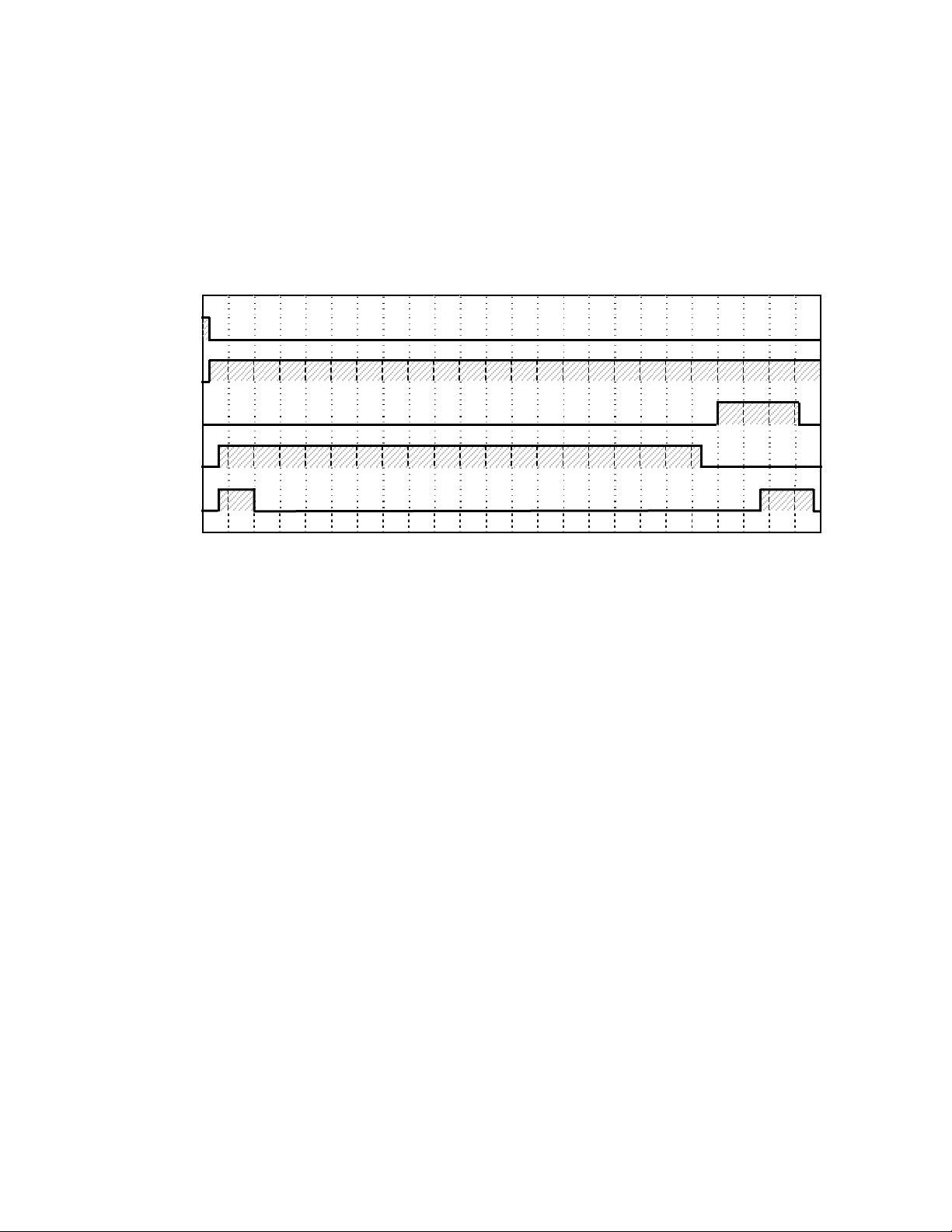
1.2. CMA-180UC Operational Cycle
The CMA-180UC Operational Cycle has a total cycle time of 2 minutes (120 seconds). The
Timing Diagram and the steps listed below detail the individual functions that are executed
during each Operational Cycle.
Seconds: 0 10 20 30 40 50 60 70 80 90 100 110 120
Instant
Start Relay
Cam Timer
Motor Cam
Rinse Cycle
Cam
Wash Cycle
Cam
Optional Drain
Pump Cam
1. With the machine powered up toggling the START switch begins a cycle.
a) Toggling the START switch energizes both the Cam Timer motor and the Instant Start
Relay. The Instant Start Relay latches ON the power to the Cam Timer motor so that
the START switch can be released a moment after it has been toggled without the Cam
Timer motor losing power.
b) After about 1.5 seconds the Cam Timer’s first cam—the Cam Timer Motor Cam—
latches ON the power to the Cam Timer motor and drops out the Instant Start Relay.
The Cam Timer motor continues to run for a total of 2 minutes, at which time it
switches OFF—resetting the Cam Timer—and waits for the next START command.
2. The Cam Timer’s third cam controls the Wash Pump. The Wash Pump comes ON about 3
seconds into the Operational Cycle and continues to run for 94 seconds. This 94-second
period is the Wash Cycle.
3. At the same time that the Wash Pump comes ON the Cam Timer’s fourth cam powers ON
the Optional Drain Pump—if one is present—and keeps it running for about 7 seconds
before powering OFF. This cam turns ON again midway through the Rinse Cycle and
stays ON for 10 seconds, turning OFF 2 seconds after the Rinse Cycle has completed.
4. About 3 seconds after the Wash Cycle has completed the Cam Timer’s second cam, which
controls the Rinse Cycle, turns ON—energizing the Water Solenoid—and stays ON for 16
seconds. This 16-second period is the Rinse Cycle.
MODEL CMA-180UC INSTALLATION & OPERATION MANUAL Rev. 1.15 Page
3

Getting Started
2. Getting Started
2.1. Introduction to CMA-180UC
The CMA-180UC is a hot water sanitizing, single rack, under-coun ter dishmachine. It is a
standalone machine featuring a self-contained booster heater. The only external connections
necessary are power supply, water supply, drainpipe, and optional chemical dispensers. The
machine uses re-circulated wash water and fresh water final-rinse.
Operation of the CMA-180UC is extremely user friendly. To initially fill the machine each day,
push the switch marked “FILL”. The machine is full when water begins to flow into the scrap tray.
The booster tank heater will maintain the wash water temperature at 155°F. The booster heater
will produce a minimum of 180°F final rinse water each cycle.
The supply water to the CMA-180UC must be a minimum of 140°F at 24 PSI (Pounds per Square
Inch) with a 6 GPM (Gallons Per Minute) flow rate and 60 GPH (Gallons Per Hour) recovery rate.
The pipe supplying the water must be ½” minimum. The plumbing connection is located at the
back of the machine. (See specification sheet on page
The drain is a 1" barbed fitting on the back of the machine for easy attachment of your drain
hose.
The machine retains the features of the standard CMA-180 Series in that it has a scrap tray and
the manner in which the tank is filled ensures that the dishes are always rinsed with fresh water
instead of re-circulated water. The CMA-180UC is the first under-counter dishmachine of its kind
to discharge soil from the wash tank into a scrap tray outside of the wash chamber. This feature
keeps the wash water much cleaner over long periods of time. The scrap tray may be emptied on
a periodic basis without interruption of the flow of work, thereby providing a much cleaner
environment for the wash and rinse cycle. There are also enhancements that can be chosen
when required such as drain pump kits and other accessories. Refer to Section
parts list and accessories available for the machine.
This manual is structured to provide a complete reference guide to the CMA-180UC. It is
presented in a manner that all users will be able to comprehend and use as an effective tool in
supporting the operation and maintenance of the dishmachine. The first section explains how the
machine is packaged and what to look for when receiving the machine.
After unpacking the machine, this manual explains how to install and set up the machine for use.
Requirements are given for plumbing, wiring, and space considerations. These attributes of the
machine are always taken into consideration by our well-trained sales representatives prior to the
order being placed. In the manual, guidance is also given for installation to ensure that the
machine will be able to run at optimum conditions.
The
Operation Section of the manual may be used for instruction and procedures when required.
We make this portion of the manual easy to understand so that all levels of operators may be
able to read and comprehend the operation of the machine. The function of the machine itself is
mostly automatic and takes little training to put into full operation. The
includes diagnostic considerations for the machine when problems occur.
The next section of the manual is the
the machine.
We are committed to providing the best machines and customer service in the food industry and
your feedback is welcome.
Parts .This section has the parts lists and wiring diagram for
2).
4 “Parts ” for the
Operation Section also
MODEL CMA-180UC INSTALLATION & OPERATION MANUAL Rev. 1.15 Page
4

2.2. Receiving and Installation
The dishwasher is shipped from the factory in a corrugated box on a wooden pallet. The
installation guidelines give a systematic procedure for setting up the machine.
Start by removing the packaging material. Unwrap the machine and check for the following
component parts:
The Wash Tank Scrap Screen is shipped inside the wash cavity of the machine. This screen must
be in place during operation. It has been designed to perform two basic functions:
1. Strain water that is circulating through the spray arms and pump assembly.
2. A basket to catch broken glass, or heavy solids that may plug the impeller.
Set the machine in place, and level from side-to-side and front-to-back.
2.2.1. Electrical1
A 50-amp, single-phase 230 volt, 60 Hz dedicated circuit should be used to supply electrical
energy to the CMA-180UC dishwasher (see specification sheet page
three power wires, which include a current carrying neutral. An additional fourth wire must be
provided for ground. CMA and local codes require the CMA-180UC to be hardwired using #8
AWG (90°C) copper wire (minimum). Approximately 4-feet of ¾” flexible conduit with power leads
(L-1, L-2, Neutral and Ground) extending out of the conduit are provided for easily connecting the
power at installation. The power connection must be located such that there is sufficient length of
the flexible conduit remaining to permit the machine to be moved for cleaning.
2.2.2. Plumbing2
The machine is equipped with a ½” NPT connection located at the lower left-hand corner (facing
the back) of the machine. A 140°F water line should be plumbed to this point (see specification
sheet page
machine to be moved for cleaning.
Important: New machines equipped with Dema Valve and Dema Flow Disc requires an
unrestricted water supply line minimum of ½”.
The supply water to the CMA-180UC must be a minimum of 140°F at 24 PSI (Pounds per Square
Inch) with a 6 GPM (Gallons Per Minute) flow rate and 60 GPH (Gallons Per Hour) recovery rate.
The pipe supplying the water must be ½” minimum. The plumbing connection is located at the
back of the machine. (See specification sheet on page
The CMA-180UC may be supplied with an optional drain pump for elevated drains. For floor
gravity drain applications the drain pump should not be used and a good commercial grade hose
needs to be connected to the discharge side of the diverter valve (drain valve) and run to the floor
drain. If removing a drain pump, safe-end (insulate electrically) the white and purple wires and
secure them out of the way. If a drain pump is used with a floor drain, the drain hose must rise 12
to 16” before dropping to the floor drain (to reduce any chance of the pump cavitations).
2). The water line used must be of sufficient length and flexibility to permit the
2).
2). This system requires
1,2
All electrical and plumbing connections must be made by a qualified person who will comply with
all available Federal, State, and Local Health, Electrical, Plumbing and Safety codes
MODEL CMA-180UC INSTALLATION & OPERATION MANUAL Rev. 1.15 Page
5

2.2.3. NOVA Detergent and Rinse Dispenser (Optional)1.
The NOVA Detergent and Rinse Dispenser has its own reference manual.
Familiarize yourself with the dispenser’s reference manual before proceeding with
installation.
1. The NOVA dispenser is pre-wired with a multi-conductor electrical cable that is to
be run through a conduit to the power block inside the control panel drawer. Use
a ½” watertight conduit meeting all local and national codes. A conduit fitting is
present on the bottom of the dispenser where the power cable exits. A mounting
plate to receive the ½” conduit is provided on the top right-hand corner (facing
the back) of the machine.
i. Run an appropriate length of ½” conduit from your dispenser to the mounting
plate where it will be secured. The conduit needs to be of sufficient length
and flexibility to permit the machine to be moved for cleaning without having
to disconnect any wiring.
ii. Run your dispenser wires through the conduit and through the enclosed area
across the top of the machine and then feed them through the access hole
provided in the back of the control panel drawer.
iii. With the machine’s power “OFF”, connect your deterg ent and rinse dispenser
wires to the power block supplied and labeled (“DISPENSER 110V - 3 AMPS
MAX”) inside the control panel drawer. The table that follows lists the
function of each conductor of the multi-conductor electrical cable.
Wire Colors Circuit Voltage Function
Gray/Violet 90 VAC-130 VAC 50/60 Hz Main AC Power
Black 90 VAC-130 VAC 50/60 Hz Main AC Power
Brown
Yellow 90 VAC-130 VAC 50/60 Hz Detergent Signal
White/Yellow 90 VAC-130 VAC 50/60 Hz Detergent Signal
Violet 90 VAC -130 VAC 50/60 Hz Rinse Signal
White/Violet 90 VAC -130 VAC 50/60 Hz Rinse Signal
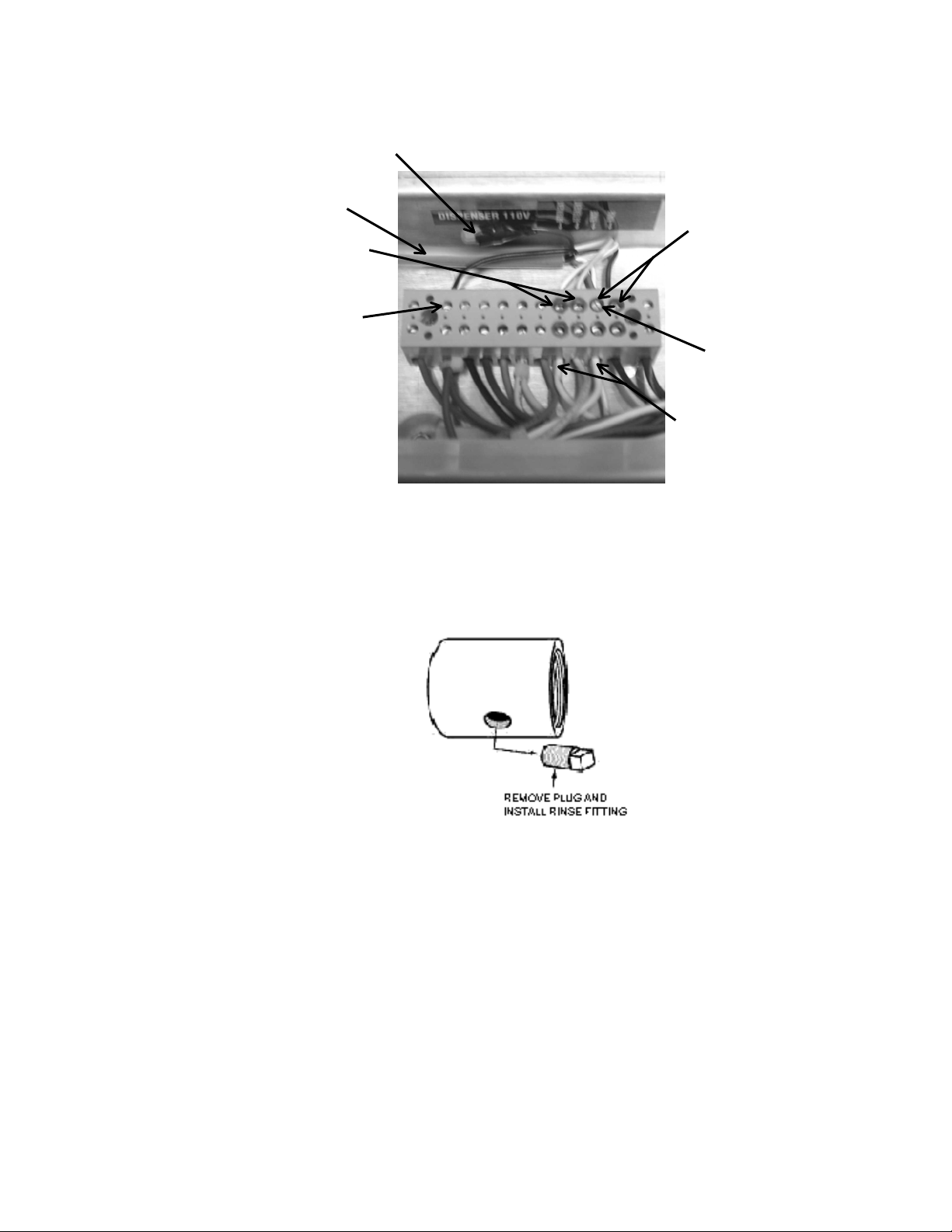
The individual conductors need to be connected as shown in Figure 2.2.3
and as described on next page.
No Connection. Insulate this wire!
This wire is LIVE!
1
All electrical and plumbing connections must be made by a qualified person who will comply with
all available Federal, State, and Local Health, Electrical, Plumbing and Safety codes
MODEL CMA-180UC INSTALLATION & OPERATION MANUAL Rev. 1.15 Page
6
(
)
Brown (LIVE) wire
Multi-conductor cable
Detergent Signal wires
(Red terminals)
Black (Main Power)
Note: In Figure 2.2.3 the machine’s wire harness was left out of the back of the
power block to more clearly show the dispenser wires.
2. Remove the plug from the mixing chamber located by the vacuum breaker on the
back of machine; and install the rinse injection fitting (supplied with your
dispenser). See Figure 2.2.4.
3. A 7/8" detergent injection hole is provided in the back of the wash tank. Remove
the S.S. plug and install the detergent fitting (supplied with your dispenser).
4. The final step of installing the CMA supplied Detergent and Rinse Dispenser is
programming it to your specific application. The reference manual supplied with
the dispenser shows you how to program it.
Keep in mind while reading the reference manual that the CMA-180UC
operates in “probe-less” mode. (This mode is selected by setting a value of
“2” in screen 21).
Screen 22 must be set to “1” (Door).
Rinse Signal wires
(Blue terminals)
Gray/Violet
(Main Power Neutral)
Same terminal as rinse neutral
Note: Machine Neutral
(White wires)
Figure 2.2.3
Figure 2.2.4.
MODEL CMA-180UC INSTALLATION & OPERATION MANUAL Rev. 1.15 Page
7
Loading...