


EST-44TALL
www.cmadishmachines.com
Rev.2.08A
12-17-19

www.cmadishmachines.com
Table of Contents
EST-44
1. SPECIFICATIONS................................................................................................. 2
1.1. EST- 44 ........................................................................................................................................... 2
2. GETTING STARTED ............................................................................................ 3
2.1. Introduction to CMA Model EST -44............................................................................................. 3
2.2. Receiving and Installation .............................................................................................................. 4
2.2.1. Box Item List ........................................................................................................................... 4
2.2.2. Electrical ................................................................................................................................ 5
2.2.2.1. Control Box Components ............................................................................................... 6
2.2.3. Plumbing ................................................................................................................................. 7
2.2.4. Scrap Tray Assembly Installation ........................................................................................... 9
2.2.5. Conveyor Drive/ Rack Speed .................................................................................................10
2.2.6. Wash Pump Assembly and Impeller .......................................................................................11
2.2.7. Table Limit Switch Installation ..............................................................................................12
2.2.8. Optional Vent Hood Adapter’s Installation ................................................................ ...........13
2.2.9. Chemical Dispenser Connection ...........................................................................................14
2.2.10. Optional Exhaust Fan Control P/N 13578.00 ......................................................................14
2.2.11. (Optional) E-Temp Booster Heater .......................................................................................15
2.3. EST-44 Safety Tips .......................................................................................................................16
3. OPERATION ........................................................................................................ 17
3.1. Beginning Operation ......................................................................................................................17
3.2. Cleaning Instructions .....................................................................................................................19
3.3. Regular Service and Maintenance Checklist .................................................................................20
3.4. Trouble Shooting ........................................................................................................................... 21
4. EST-44/66 CUSTOMER NOTICE ........................................................................ 3
5. PARTS MANUAL .................................................................................................. 5
5.1. Initial Parts Kit ............................................................................................................................... 5
5.2. Exploded View Drawings ............................................................................................................... 6
5.2.1. Cabinet Assembly ................................................................................................................... 6
5.2.2. Control Box Assembly (3 Phase) ............................................................................................ 7
5.2.1. Control Box Assembly (1 Phase) ............................................................................................ 8
5.2.2. 480V Control Box Assembly (480V machines only) ............................................................... 9
5.2.3. Curtain and Optional Vent System ........................................................................................10
5.2.4. Old Wash Temperature Control System (Square Flange) .....................................................11
5.2.5. New Wash Temperature Control System (Triangular Flange) ..............................................12
5.2.6. Rinse Temperature Control System .......................................................................................13

www.cmadishmachines.com
5.2.7. Wash Pump Assembly (3 Phase) ............................................................................................14
5.2.8. Wash Pump Assembly (1 Phase) ............................................................................................15
5.2.9. Power Rinse Pump Assembly .................................................................................................16
5.2.10. Drain System Assembly..........................................................................................................17
5.2.11. Plumbing System Assembly (Auto-Fill) .................................................................................18
5.2.12. Plumbing System Assembly (Final Rinse) ..............................................................................19
5.2.13. Wash System Assembly ..........................................................................................................20
5.2.14. Rocker Arm Assembly ............................................................................................................21
5.2.15. Start Switch and Rinse Switch Assembly (Effective May 2014) .............................................22
5.2.15.1. Right-to-Left Assembly .................................................................................................22
5.2.15.2. Left-to-Right Assembly .................................................................................................23
5.2.16. Start Switch and Rinse Switch Assembly ...............................................................................24
5.2.17. Door Switch Assembly (Effective August, 2014) ....................................................................25
5.2.18. Optional E-Temp Heater (Effective September 1, 2018) .......................................................26
5.2.19. Optional E-Temp Heater .......................................................................................................27
5.2.20. Unique Parts For EST-44 Tall machines...............................................................................28
6. TABLE LIMIT SWITCH (P/N 13469.20) .......................................................... 29
7. DRAIN WATER TEMPERING KIT (OPTIONAL) ........................................ 30
8. ELECTRICAL DIAGRAM FOR 240V, 3 PHASE EST-44 ........................... 311
9. ELECTRICAL DIAGRAM FOR E-TEMP HEATER ONLY ....................... 322
10. ELECTRICAL DIAGRAM FOR 480V EST-44 .............................................. 333
11. ELECTRICAL DIAGRAM FOR 240V,1 PHASE EST-44 ............................ 344

MODEL EST-44 Service and Parts Manual Rev. 2 .08A Page
2
1. Specifications
1.1. EST- 44
WATER CONSUMPTION
PER RACK (FINAL RINSE)
.46 GAL.
.46 GAL.
PER HOUR (FINAL RINSE)
114 GAL.
114 GAL.
CONVEYOR SPEED
FEET PER MINUTE
6.75
6.75
OPERATING CAPACITY
RACKS PER HOUR (NSF rated)
249
249
OPERATING TEMPERATURE
WASH RECOMMENDED
140° - 150° F
150° - 160° F
PUMPED RINSE RECOMMENDED
140° - 150° F
150° - 160° F
FINAL RINSE RECOMMENDED
140° - 150° F
180° - 195° F
WATER REQUIREMENTS
INLET TEMPERATURE (MIN)
140° F
180° F
WATER INLET SIZE
1/2”
FINAL RINSE SIZE
1/2”
DRAIN SIZE
2”
FINAL RINSE PRESSURE
20 PSI
HEATERS
WASH HEATER
13.3 KW/240V(1 phase)
13KW/208V(3 phase)
RINSE HEATER
3KW/240V, 2.25KW/208V
MOTORS
WASH PUMP
1 HP
RINSE PUMP
1/3 HP
CONVEYOR
1/8 HP
DIMENSIONS
DEPTH
25-1/8”
WIDTH
44”
HEIGHT
55 -1/2”-56-1/2”
STANDARD TABLE HEIGHT
32 ½” adjusts to 34”
MAX CLEARANCE FOR DISHES
19”
VENTILATION REQUIREMENTS CFM
600 Total, 400 at exit, 200 at entrance
STANDARD RACKS
VOLTS
PHASE
AMPS
AMPS(Tall)
ELECTRICAL RATING 208
1
71
N/A
240
1
80
N/A
208
3
55
60.5
240
3
62.5
69
480
3
24
27
SHIPPING WEIGHT
662#
(300kg)
High temp
Low Temp

Getting Started
MODEL EST-44 Service and Parts Manual Rev. 2 .08A Page
3
2. Getting Started
2.1. Introduction to CMA Model EST -44
The EST is designed to give maximum cleaning in 44 inches. It represents the cleaning power
of machines twice its length. The curtains incorporated in the dishwasher minimize the transfer
of water from tank to tank during the wash and sanitizing procedures.
The energy costs for running the new EST-44 have been greatly reduced, by the introduction of
our new Stage Washing Process. The EST-44 Conveyor dishwasher (EST is abbreviation for
ENERGY STAR) lowers gallon/rack ratings and is directly related to CMA’s new Power-Rinse
Stage that has been introduced. The EST-44 new Re-circulating Wash and new Power-Rinse
Stage greatly reduce the amount of chemicals being used, thus adding a significant cost
reduction and energy efficiency to its’ operation.
The EST-44 can be used as a high or low temperature dishwasher, with the new wash tank and
power rinse tank designs, both having their own re-circulating pumps. The Power Rinse Stage
provides a fresh cleansing rinse, before the dish rack advances into the Power Rinse and Fresh
Water and Sanitizing Rinse Stages.
The initial-fill water and the final rinse water that is supplied to the EST-44 must be a minimum of
140°F, in low-temperature applications, while high-temperature machines will require two water
lines; one at a minimum water temperature of 140°F to fill the dishwasher, and the second with a
minimum of 180°F for the final rinse. With the introduction of the new optional E-Temp Booster
Heater, it will be offered fully integrated to the dishwasher.
The EST-44 also features a stainless steel scrap accumulator tank and tray, which must be
emptied on a periodic basis, as necessary. The EST machine is designed to deliver 0.49 gallons
of fresh rinse water for each rack. This water flows from the rinse and power-rinse tanks into the
wash tank, and then overflows into the scrap tray, carrying any debris that may have fallen into
the wash tank, thereby providing a much cleaner environment for the washed and rinsed dishes.
If preferred, there are also options such as a Corner Feed System, optional Vent Hood Adapters,
Exhaust Fan Control Circuits and a Drain Tempering Kit. CMA also offers a full line of other
machine accessories, including stainless steel dishtables. (See equipment catalog)
DISCLAIMERS
CMA expressly disclaims any and all warranties, express or implied, relating to the installation of any and all CMA equipment that
is installed by chemical dealers, contracted servicers or third party servicers to CMA equipment. If the installation instructions
are not followed exactly (to the letter), or, if any person or company conducting the installation of the CMA equipment, revise the
installation procedures or alter the instructions in any manner, the CMA warranty becomes void. If, due to the improper
installation of CMA equipment, this equipment ceases to operate properly or affects other parts of the CMA dishwashing
equipment, in that the other parts become defective, the CMA warranty becomes void. CMA will not be liable or responsible or
warrant CMA equipment, due to improper installation of any CMA model dishwasher.
CMA does NOT endorse “Tankless On-Demand” water heaters for use on CMA Dishmachine products. On most applications, the
volume of hot water required for commercial dishmachines exceeds the capacity of these types of heating sources. You will find
that most, if not all, commercial dishmachines have been programmed with auto-filling features that require quick filling, with a
designated limited time.
CMA DOES endorse, and highly recommends, the standard “tank” style water heaters, sized properly to handle each particular
facility with their water heating requirements. A “tank” style water heater stores and supplies a large capacity of pre heated water
before providing hot water to the dishmachine. To meet required health codes, there must be a reliable and consistent flow of
adequate hot water supplied to the dishmachine. If the facilities’ “tank” style water heater is marginal in size, C MA recommends
installing a proper size Hatco Booster Heater, a CMA’s E -Temp 40 or 70-degree-rise Booster Heater (that can be installed on CMA
Conveyors), or a CMA Temp-Sure Booster Heater (for door and undercounter dishmachines). All are designed to adequately
achieve results.
Important: Make sure incoming power supply corresponds to the voltage listed on the data plate. If the voltage is too low (206V or
less), the heating elements will not reach desired temperature specified by manufacturer, and performance will be compromised.
The heating element needs to be sized according to the facilities available voltage, which must be noted on your purchase order
to CMA for a special dishmachine. Special lower voltage higher kilowatt heaters are available upon request.
Make sure a fused disconnect switch or circuit breaker (not supplied) is installed in the electrical service lines supplying this
dishwasher and should meet the requirements of your local electrical code.
Getting Started
MODEL EST-44 Service and Parts Manual Rev. 2 .08A Page
4
2.2. Receiving and Installation
2.2.1. Box Item List
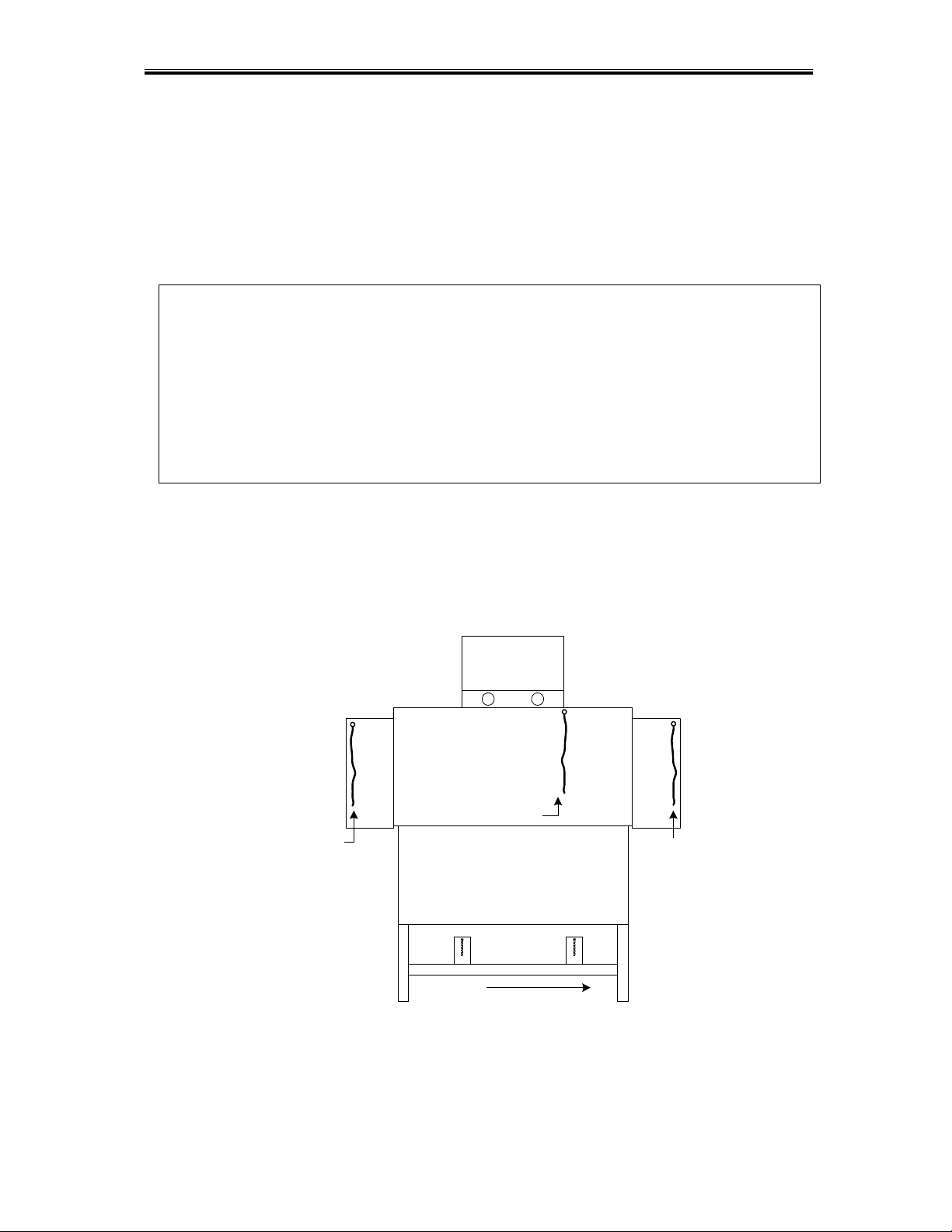
When you receive your new EST-44, prior to installation of the dishwasher, remove the box
containing the all items needed for the installation. (See item list below)
Literature & Manuals
Instructional Operation Video
Scrap Tank Assembly, w/Mounting Bracket
Curtains Interior and Exterior, w/Rods
Exterior Wrapper Shields
Installation Hardware
Operation Wall Chart
Optional Vent Hood Adapters when ordered.
Start by first installing the Scrap Tray Assembly (see Scrap Tray Assembly, Section 2.2.4),
along with the Overflow Chute, then the two wrapper shields and the exterior and interior
curtains and rods, which are shipped inside the machine. All of the wash-arms are fully
installed over the wash and power-rinse tanks. There are a total of three curtains used in the
EST-44: two long-exterior curtains and one short-interior curtain, all with their own curtain rods.
(See Figure 2.2-1, below)
EST-44
1
2
3
EXTERIOR
LONG CURTAIN
DISH FLOW
DISHMACHINE FRONT VIEW
INTERIOR
SHORT
CURTAIN
EXTERIOR
LONG CURTAIN
Figure 2.2.1
Getting Started
MODEL EST-44 Service and Parts Manual Rev. 2 .08A Page
5
2.2.2. Electrical
*
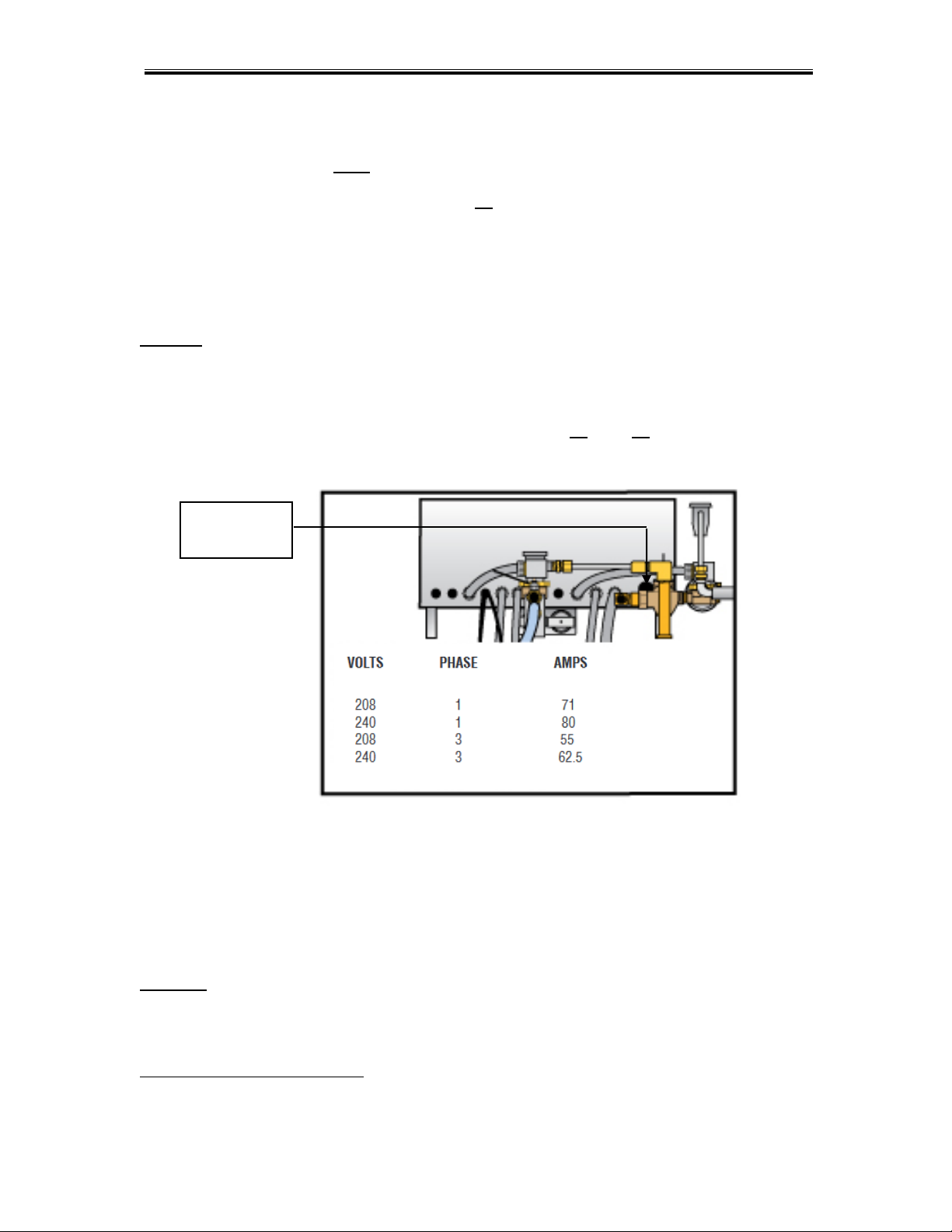
The CMA Model EST-44 Conveyor can be ordered as Single-Phase or Three-Phase, using
208v to 240v. The machine must be connected to a dedicated circuit. (See Figure 2.2.2 below
for amp draw). When installing a Three-Phase machine, check the voltage on all three
incoming lines, and place the highest leg on the L2 terminal. (This is called a high-leg, stinger-
leg, or Wild-leg.)
Prior to installation make sure the electrical supply is compatible with the specifications on the
machines data plate.
WARNING: Electrical and grounding connections must comply with the applicable portions of the
National Electrical Code and/or other local electrical codes.
Note: For supply connections, use copper wire only rated at 90 degree C minimum.
Warning: To prevent excessive overloads and component damages, it is essential for the
Dispenser Power Supply to be wired to the supplied Power Block on all conveyors. The CMA-
supplied power block has been pre-wired to the wash heater contactor L1 and L3 terminals, to
assure a correctly balanced power, as well as accurate surrounding components.
Only for dispensers requiring constant power, connect to L1 and L3 of main contactor;
otherwise, use the Dispenser Power Block that has been provided.
Figure 2.2.2
On a 3-phase machine the water pump motors are also 3-phase and, depending on the terminal
that each phase is connected to, the motor can rotate in either direction. Check the direction of
rotation by removing the dust cap on the back of the motor. The motors must turn clockwise,
when looking at the shaft from the back of each motor. To change the direction of rotation,
switch any two power lead wires at the motor.
DANGER: ALWAYS TURN OFF THE DISHWASHER’S MAIN POWER SUPPLY BEFORE
SERVICING THE DISHWASHER. ALTHOUGH THE MACHINE’S MAIN POWER SWITCH IS
“OFF”, THE MAIN CONTACTOR LEADS WILL STILL HOLD VOLTAGE.
*
Electrical and plumbing connections must be made by a qualified person who will comply with all
available Federal, State, and Local Health, Electrical, Plumbing and Safety codes
Main Power
Knockout
Getting Started
MODEL EST-44 Service and Parts Manual Rev. 2 .08A Page
6
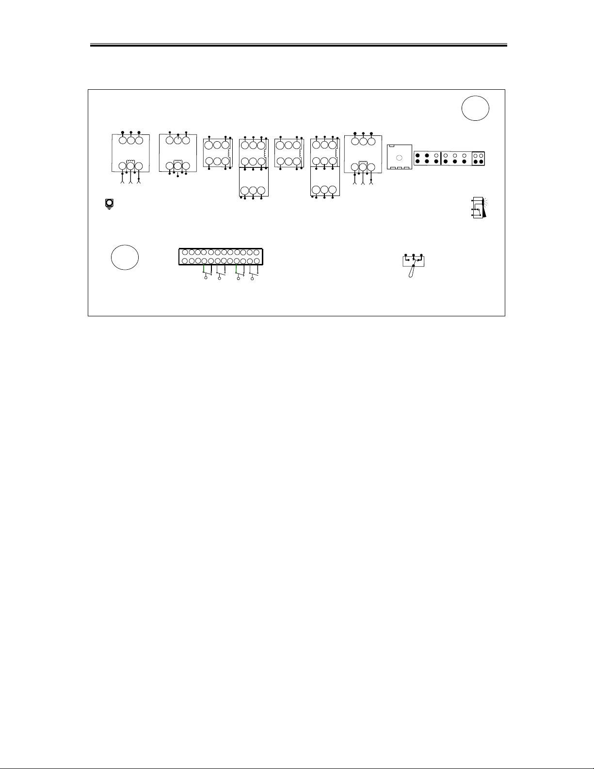
2.2.2.1. Control Box Components
T
1
T
2
T
3
L
1
L
2
L
3
POWER
SWITCH
3 2
7
A
U
T
O
M
A
N
U
A
L
G
R
O
U
N
D
1
2
3
6
WASH HEATER
CONTACTOR
WASH
TANK
PRE-RINSE
TANK
T1
T2
T3
OVERLOAD
RELAY
95
1
2
3
4
5
6
7
8
T
1
L
1
L
3
T
3
L
2
T
2
A
1
A
2
RINSE HEATER
CONTACTOR
T
1
T
2
L
1
L
2
L
3
T
3
1
A
A
2
RINSE PUMP
CONTACTOR
T
1
L
1
L
3
T
3
L
2
T
2
A
1
A
2
WASH PUMP
CONTACTOR
T
1
T
2
L
1
L
2
L
3
T
3
1
A
A
2
T1
T2
T3
OVERLOAD
RELAY
95
CONVEYOR
CONTACTOR
M
A
I
N
C
O
N
T
A
C
T
O
R
L
3
L
2
L
1
T
3
T
2
T
1
B
O
O
S
T
E
R
H
E
A
T
E
R
C
O
N
T
A
C
T
O
R
L
3
L
2
L
1
T
3
T
2
T
1
CHEMICAL
DISPENSER
208-230V
9
10
11
14
16
17 18
19
12
13
15
1.
Main Contactor
11.
Detergent Terminals
2.
Wash Tank Heater Contactor
12.
Dispenser Power Supply Terminals
3.
Power Rinse Heater Contactor
13.
On-Off Power Switch
4.
Power Rinse Motor Contactor w/overload
14.
Auto/Manual Switch
5.
Wash Pump Contactor
15.
E-Temp Power Cable Knockout
6.
Conveyor Contactor w/overload
16.
Main Power Knockout
7.
E-Temp Heater Contactor (Optional)
17.
Wash Tank Float Terminals
8.
Conveyor Timer
18.
Power Rise Float Terminals
9.
Table Limit Switch Terminals
19.
Ground Terminal
10.
Sanitizer/Rinse Terminal Terminals

Getting Started
MODEL EST-44 Service and Parts Manual Rev. 2 .08A Page
7
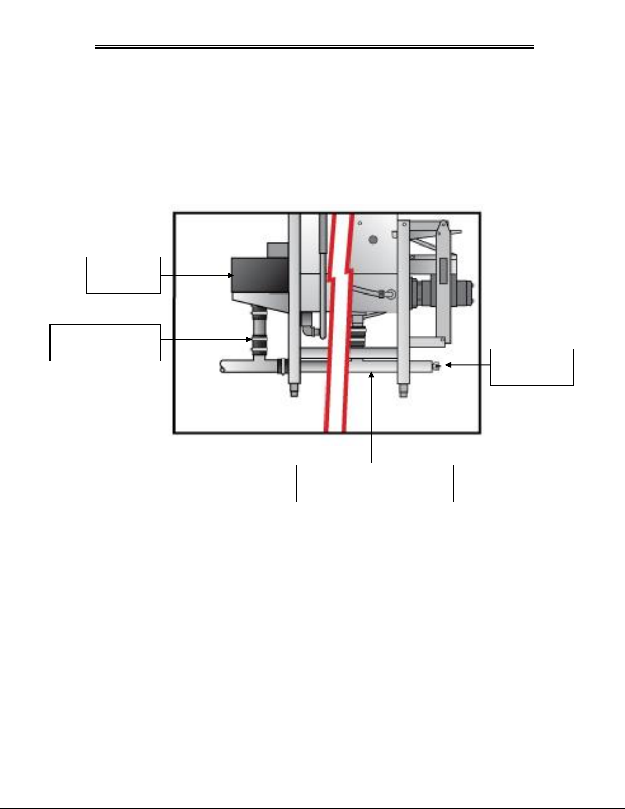
2.2.3. Plumbing
*
Note: The required flowing water pressure to the dishwasher is 15-65 PSIG. If pressures higher
than 65 PSIG are present, a pressure regulating valve must be installed in the water line to the
dishwasher (by others). If flowing pressure is lower than 15 psi, improper machine operation may
result.
Notice to Plumber: The plumber connecting this machine is responsible for making certain that
the water lines are THOROUGHLY FLUSHED OUT BEFORE connecting to the dishwasher.
Ask your municipal water supplier for details about your local water conditions prior to installation.
Recommended water hardness is 3 grains per gallon or less.
Note: high iron levels in the water supply can cause staining and may require an iron filter. High
chlorine levels in the water supply can cause pitting and may require a chloride removal system.
If an inspection of the dishwasher or booster heater reveals lime buildup after the equipment has
been in service, water treatment is recommended. If water softener is already in place, ensure
there is a sufficient level of salt.
The water supply connection is made with two ½” hot water lines; the valves are located at the
top of the machine, behind the main control box. The water supplied to the machine must be a
minimum of 140° F to the main fill valve and a minimum of 180° F to 195° F for a high
temperature final rinse, with no more than 140° F for a lower temperature final rinse. (See Figure
2.2.3a below)
Figure 2.2.3a
To set the final rinse pressure, the final rinse must be running. Turn the adjustment screw
clockwise to increase final rinse pressure; and counter-clockwise to decrease the pressure set
the final rinse pressure to 20-psi ±5 psi. (Set to 22 - 23 psi for optimum running pressure)
*
Electrical and plumbing connections must be made by a qualified person who will comply with all
available Federal, State, and Local Health, Electrical, Plumbing and Safety codes
Main water inlet
valve connection ½”
Final rinse water inlet
valve connection ½”
Pressure
regulator
Vacuum
Breaker
Getting Started
MODEL EST-44 Service and Parts Manual Rev. 2 .08A Page
8
There are two 2” drain openings off both ends of the dishwasher, however only one connection
is on the horizontal drainpipe. Place the 2” drain plug, supplied in the end of the pipe not being
connected to the drain line (See Figure 2.2.3.b below).
Note: One of the ends of the horizontal drainpipe has a stopper cap on it – simply move the cap
to the other end, if it’s currently on the end needed for the drain connection.
The Scrap Tray Assembly is placed inside the machine for shipping. Follow the instructions
provided in 2.2.4 Scrap Tray Assembly to properly install to the dishmachine.
Figure 2.2.3b
Scrap Tray
Main Drain & Scrap
Drain Connection
Drain Stopper
Cap
Main Drain Line from Wash &
Power Rinse Tanks
Getting Started
MODEL EST-44 Service and Parts Manual Rev. 2 .08A Page
9
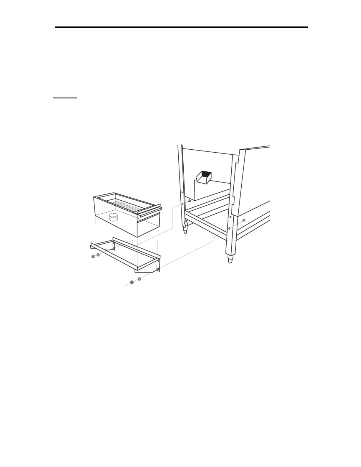
2.2.4. Scrap Tray Assembly Installation
The Scrap Tray Assembly and Overflow Chute, which were shipped inside the machine, can
easily be installed by executing the following steps: Figure 2.2.4 below illustrates the assembly,
as it would appear for a Left-to-Right machine – (a Right-to-Left machine would simply be the
mirror image).
Caution:
1. For proper spacing, the SS flat washer must not be located between the head of the truss
head bolt and the inside of the machine.
2. The Illustration below shows the correct placements of the scrap trap holder. Do not
install upside down, otherwise water deflection takes place.
Figure 2.2.4
1. Remove items from their packaging and verify that all “installation hardware” was included.
2. Secure the scrap trap holder to the dishmachine by using the four ¼-20 X ½” Hex Head
Bolts, the ¼” SS Flat Washers, and the ¼”-20 Nylon Lock Nuts that were provided.
3. Set the scrap trap body—with the scrap trap drawer inserted—into position on the scrap trap
holder. (Attach the drain as specified in Section 2.2.3)
Getting Started
MODEL EST-44 Service and Parts Manual Rev. 2 .08A Page
10
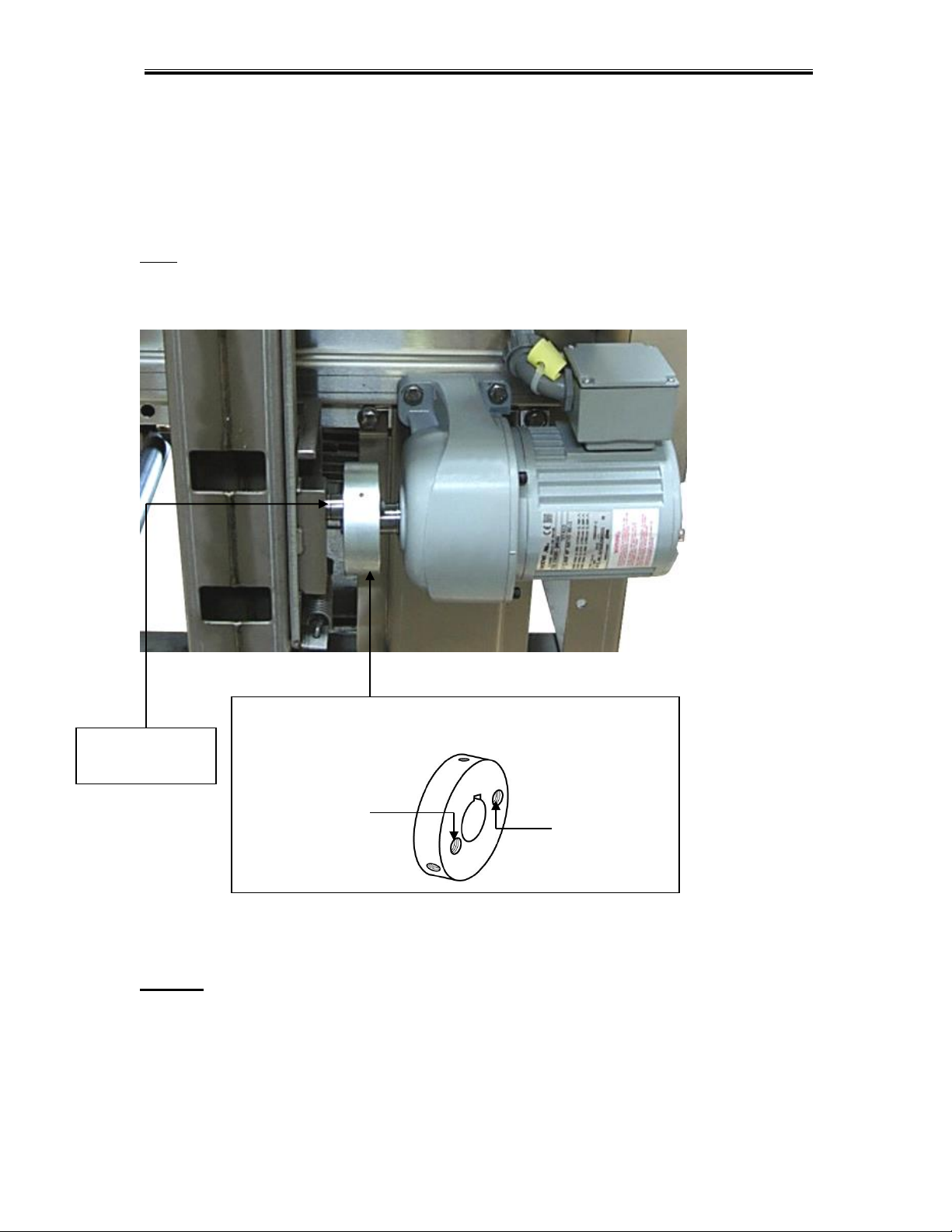
2.2.5. Conveyor Drive/ Rack Speed
The Conveyor Drive Cam below shows the two different conveyor drive cam speed settings; for
standard 243 Racks/Hour and a slower 205 Racks/Hour (See Figure 2.2.5). By changing the
Drive Cam Bearing location, the racks will travel through the machine slower.
Note: If the dishwasher is being used in a very heavy soil environment, changing the rack speed
to 205 racks/hour will slow down the racks as they pass-through the dishwasher, allowing them
to receive more chemical and water “contact time”.
Figure 2.2.5
Caution: DO NOT GET IN THE PATH OF THE CONVEYER DRIVE ASSEMBLY, ROCKER
ARM, OR CONVEYOR BAR, WHILE MACHINE IS IN OPERATION. DO NOT REACH INTO
THE ROCKER ARM ASSEMBLY WITHOUT FIRST MAKING SURE THE DISHWASHER IS
TURNED “OFF” AT THE MAIN PANEL. EVEN WITH THE MACHINE’S POWER SWITCH
“OFF”, THE MAIN CONTACTOR LEADS WILL STILL CARRY VOLTAGE.
Conveyor Drive Cam
P/N 13505.14
243 RACKS/HOUR
205 RACKS/HOUR
Conveyor Cam
Bearing
Getting Started
MODEL EST-44 Service and Parts Manual Rev. 2 .08A Page
11
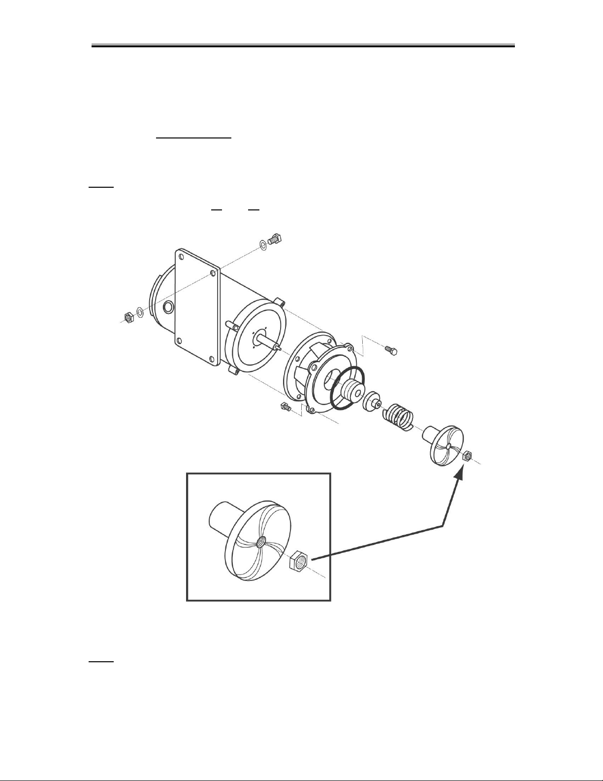
2.2.6. Wash Pump Assembly and Impeller
The standard wash pump motor is three-phase and can operate clockwise, as well as counter-
clockwise; the Nylon Lock Nut used to hold the impeller in place (See Figure 2.2.6), is very
important. When servicing the Wash Pump Assembly and replacing the seals, make sure it is
secured properly; otherwise, if the motor turns the wrong direction, the impeller may spin-off the
motor shaft causing damage to the impeller.
Note: ALWAYS CHECK THAT THE DIRECTION OF THE MOTOR ROTATION IS CLOCKWISE,
WHEN REINSTALLING THE WASH PUMP. IF THE MOTOR IS TURNING COUNTER-
CLOCKWISE, EXCHANGE L1 AND L3 WIRES ON MAIN CONTACTOR
Figure 2.2.6
Note: The Nylon Lock Nut indicated by the arrow in Figure 2.2.6 must be removed before
attempting to remove the water pump impeller.
Getting Started
MODEL EST-44 Service and Parts Manual Rev. 2 .08A Page
12
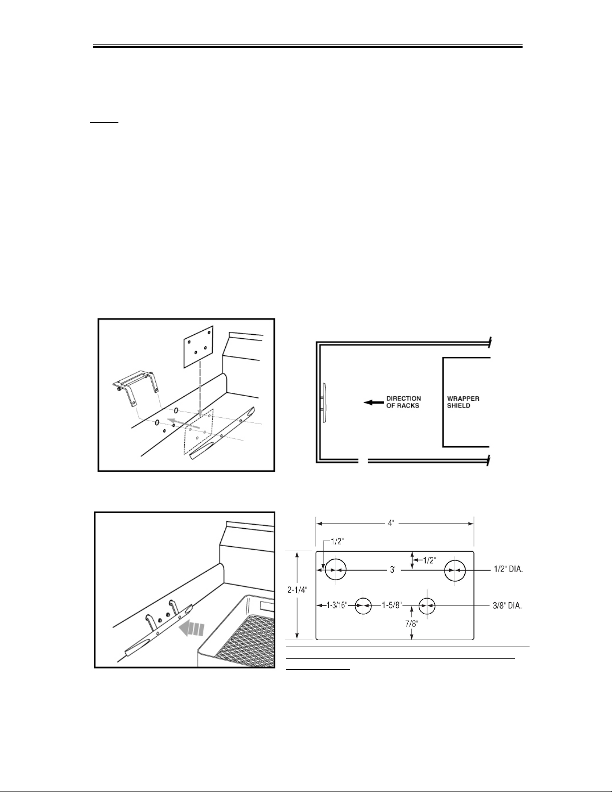
2.2.7. Table Limit Switch Installation
The Model EST-44 is shipped with a Table Limit Switch fully wired and connected in the main
control box, ready to be installed on the clean side of the dishtable. The Table Limit Switch
MUST be installed to prevent dishrack and Conveyor Drive damage.
1. Remove the template that was shipped to hold the table-limit switch assembly
together.
2. Remove the activator bar (Figure 2.2.7a).
3. Position the template in the middle of the clean side of the dishtable.
4. Mark the end of the table, where the holes need to be drilled (Figure 2.2.7b).
5. Drill the holes.
6. Attach the Table Limit Switch, using the hardware supplied.
7. Reattach the activator bar removed earlier.
8. Test that it functions properly (Figure 2.2.7c).
Figure 2.2.7a Figure 2.2.7b
Note: This terminal is not actual size ,not to be used
for installation!
Figure 2.2.7c
Getting Started
MODEL EST-44 Service and Parts Manual Rev. 2 .08A Page
13
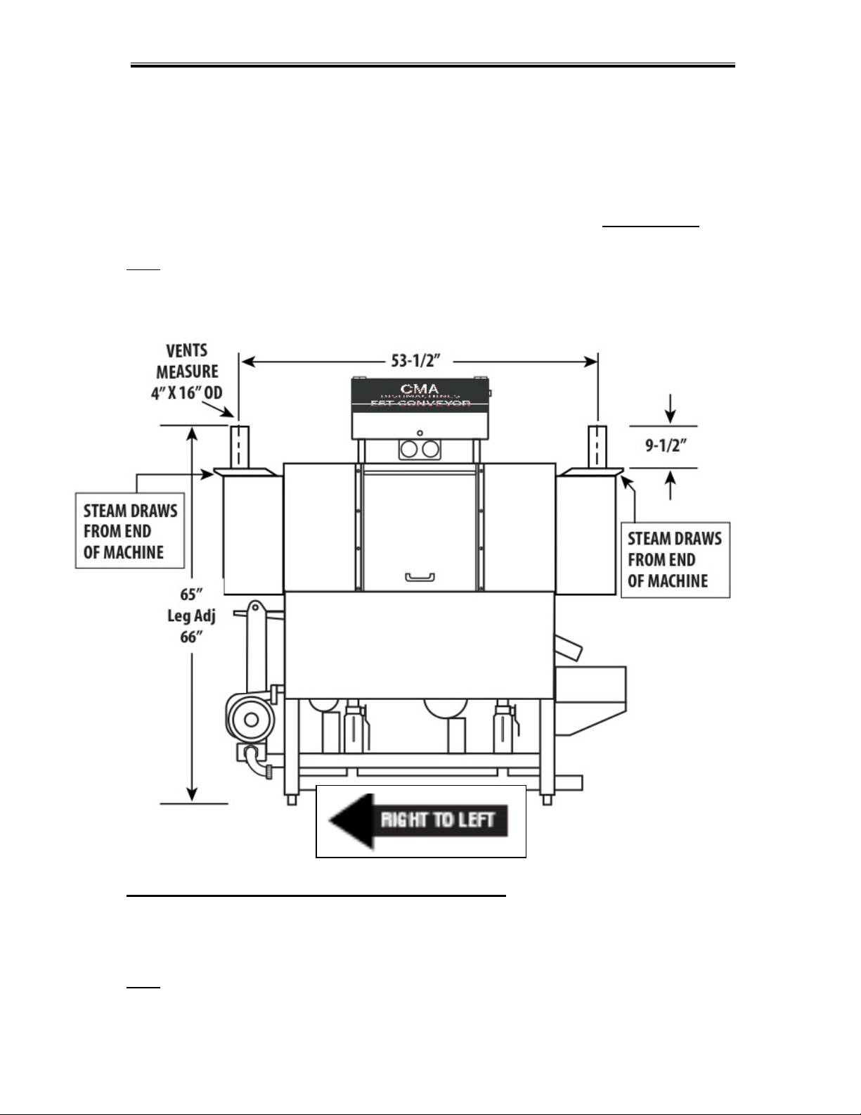
2.2.8. Optional Vent Hood Adapter’s Installation
CMA Vent Hood Adapters have been designed and engineered to draw only the steam that is
released from underneath the curtains at the entrance and exit of the EST-44 conveyor
dishwasher. This will allow the dishwasher to retain the heat within the machine, reducing the
energy consumption of the dishwasher. To maintain proper CFM’s (600), and not evacuate the
heat from the dishwasher tanks, CMA Vent Hood Adapters (PN # 13901.82) MUST be used.
Note: ON ALL PANT-LEG-STYLE VENT SYSTEMS, BY MODIFYING OR INSTALLING AN
UNAUTHORIZED BRAND OF VENT HOOD ADAPTER, IT WILL VOID THE CMA
MANUFACTURERS’ WARRANTY.
Adjusting the internal baffles of the Vent Hood Adapters:
Once the vent hood adapters have been installed, completely close the internal baffle using two
7/16” wrenches. Run the dishwasher to create heavy steam buildup; start at the exit end of the
dishwasher, open the baffle enough to draw the steam into the vent system. Then repeat the
same process on the entrance side of the dishwasher.
Note: ONLY ONE OF THE TWO NUTS ON EACH BAFFLE IS USED TO TIGHTEN AND KEEP
THE INTERNAL BAFFLE FROM BEING REPOSITIONED.
Exit
Entrance
Getting Started
MODEL EST-44 Service and Parts Manual Rev. 2 .08A Page
14
2.2.9. Chemical Dispenser Connection
*
The Model EST-44 will supply both the main power and the signals for the Detergent and
Sanitizer/Rinse Aid. Connect the chemical dispenser main power leads, to the supplied power
terminals. (See Figure 2.2.9)
Connect the Detergent and Rinse Aid signal wires to the supplied signal terminals (See Figure
2.2.9)
Sanitizer/Rinse
Signal only
Detergent Signal only
Dispenser Power only
208 to 240 Volts
Figure 2.2.9
Note: Sanitizer/Rinse and Detergent signals can draw more than 0.5 Amps.
Note: Use only commercial-grade detergents and rinse aids recommended by your chemical
professional. Do not use detergents and rinse aids formulated for residential dishwashers.
Low Temperatures chemical-sanitizing dishmachines must not exceed 6% sodium hypochlorite
solution (bleach) as the sanitizing agent. Higher levels may damage stainless or components.
Follow the directions precisely that are on the litmus paper vial and test the water on the surface
of the bottom of the glasses.
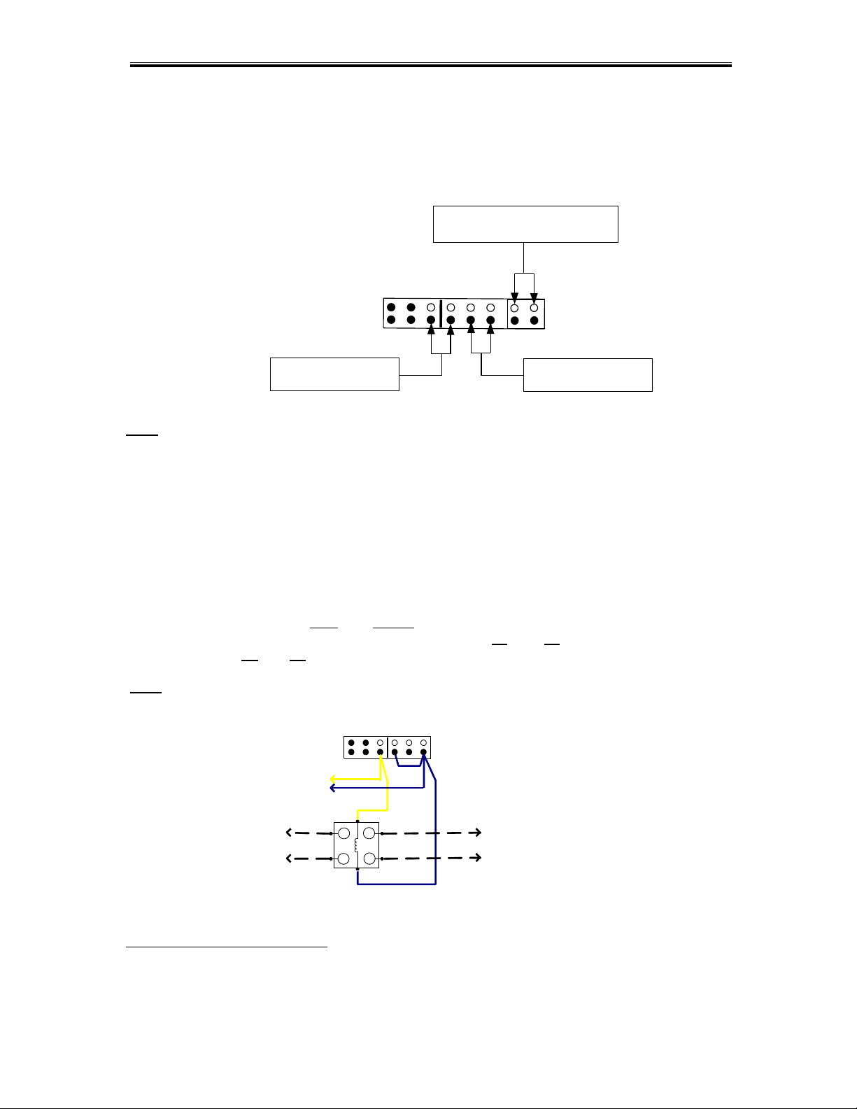
2.2.10. Optional Exhaust Fan Control P/N 13578.00
First, when field-installing the Optional Exhaust Fan Control, locate the detergent signal terminals
on the dispenser terminal block; mount the contactor, that was supplied with the kit, securely to
the control box; connect the Blue and Yellow wires, also supplied in the kit, to the rinse signal
terminals; attach the power for the exhaust fans to the L1 and L2 incoming terminals of the
contactor, and the T1 and T2 terminals, to the exhaust fan.
Note: Wires for exhaust fan to be supplied by electrician. (See Figure 2.2.10)
T1
T2
L1
L2
FAN CONTACTOR P/N 404.81
TERMINAL BLOCK
WIRES FROM THE
POWER SOURCE *
WIRES TO THE FAN
* 220 VAC OR 110 VAC
SUPPLIED BY ELECTRICIAN
RINSE SIGNAL
Figure 2.2.10
*
Electrical and plumbing connections must be made by a qualified person who will comply with all
available Federal, State, and Local Health, Electrical, Plumbing and Safety codes
Getting Started
MODEL EST-44 Service and Parts Manual Rev. 2 .08A Page
15
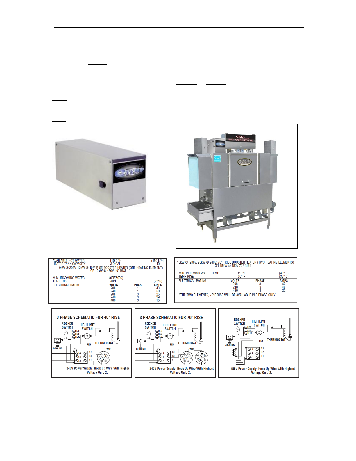
2.2.11. (Optional) E-Temp Booster Heater
*
The Optional E-Temp Booster Heater can only be ordered with a dishwasher, already installed at
the factory; it cannot be installed in the field. The E-Temp Booster heater will be fully integrated
into the EST-44 conveyors’ plumbing system. It will require its’ own power supply of 208 volts to
240 volts, in single-phase or three-phase. The unit can be specially ordered as a 480-volt unit, in
three-phase only; temperature is available in a 40° rise or 70° rise. The E-Temp Booster heater
contactor is located in the EST-44 Main Control Box (See item 7, page 6).
Note: E-Temp heater is shipped on the machine empty to prevent freezing. When machine
is powered up for the first time, the booster heater must be filled by pressing and holding
rinse switch to prevent heater damage.
Note: 70° degree rise E-temp Booster Heater is only available in Three-Phase.
*
Electrical and plumbing connections must be made by a qualified person who will comply with all
available Federal, State, and Local Health, Electrical, Plumbing and Safety codes
 Loading...