

Climette Ca0516k, Ca0616kr, Ca0816kp Owner's Manual
CA_
SERIES
OWNER’S GUIDE
For future reference, fill in the information below and
keep this guide in a safe place. Please keep a copy of
your receipt for warranty purposes.
This book is for CA0516K mechanical control air
conditioners and CA0616KR and CA0816KR
electronic control room air conditioners.
DEALER NAME ___________________________________________________
ADDRESS ________________________________________________________
TELEPHONE _____________________________________________________
MODEL/CATALOG NUMBER _______________________________________
SERVICE DISCRETE NUMBER _____________________________________
SERIAL NUMBER _________________________________________________
PLEASE KEEP A COPY OF YOUR RECEIPT FOR WARRANTY PURPOSES.
CONTENTS
Page
A FEW WORDS ABOUT YOUR NEW
AIR CONDITIONING UNIT . . . . . . . . . . . . . . . . . . . . . .2
REQUIRED TOOLS. . . . . . . . . . . . . . . . . . . . . . . . . . . . . . . . . .2
INSTALLATION. . . . . . . . . . . . . . . . . . . . . . . . . . . . . . . . . . .3-7
POWER CORD. . . . . . . . . . . . . . . . . . . . . . . . . . . . . . . . . . . . . .3
WIRING & LOCATION . . . . . . . . . . . . . . . . . . . . . . . .4
WINDOW INSTALLATION . . . . . . . . . . . . . . . . . . . . . . . .5
STORM WINDOW APPLICATIONS . . . . . . . . . . . . . . . .7
OPERATION . . . . . . . . . . . . . . . . . . . . . . . . . . . . . . . . . . . . . .7 -9
MECHANICAL CONTROLS . . . . . . . . . . . . . . . . . . . . . . .7
ELECTRONIC CONTROLS. . . . . . . . . . . . . . . . . . . . . . . . .7
ENERGY SAVING TIPS . . . . . . . . . . . . . . . . . . . . . . . . . . . .9
Page
MAINTENANCE . . . . . . . . . . . . . . . . . . . . . . . . . . . . . . . . . . . . 9
CLEAN FILTER . . . . . . . . . . . . . . . . . . . . . . . . . . . . . . . . . . . 9
CLEAN FRONT PANEL . . . . . . . . . . . . . . . . . . . . . . . . . . . 9
CLEAN BASEPAN . . . . . . . . . . . . . . . . . . . . . . . . . . . . . . . . 9
CARE OF THE REMOTE CONTROL . . . . . . . . . . . . . . . 9
REMOTE CONTROL BATTERY
REPLACEMENT . . . . . . . . . . . . . . . . . . . . . . . . . . . . . . . . 9
TROUBLESHOOTING . . . . . . . . . . . . . . . . . . . . . . . . . . . 10-12
Part Number 421 02 9100 00 - Printed 02/08
P1_Owners Guide - 5K,6K, 8K.pdf 30/01/2008 1:06:42 PM
CA_
SERIES
2
A FEW WORDS
ABOUT YOUR NEW
AIR CONDITIONING UNIT
Thank you for choosing a Climette room air conditioner
to cool your home or office. In addition to providing
economical cooling comfort, Climette room air conditioners filter and dehumidify the air in the room.
This owner’s guide will supply all the information you
need to install, operate, and maintain your new air
conditioning unit. Please read the entire manual
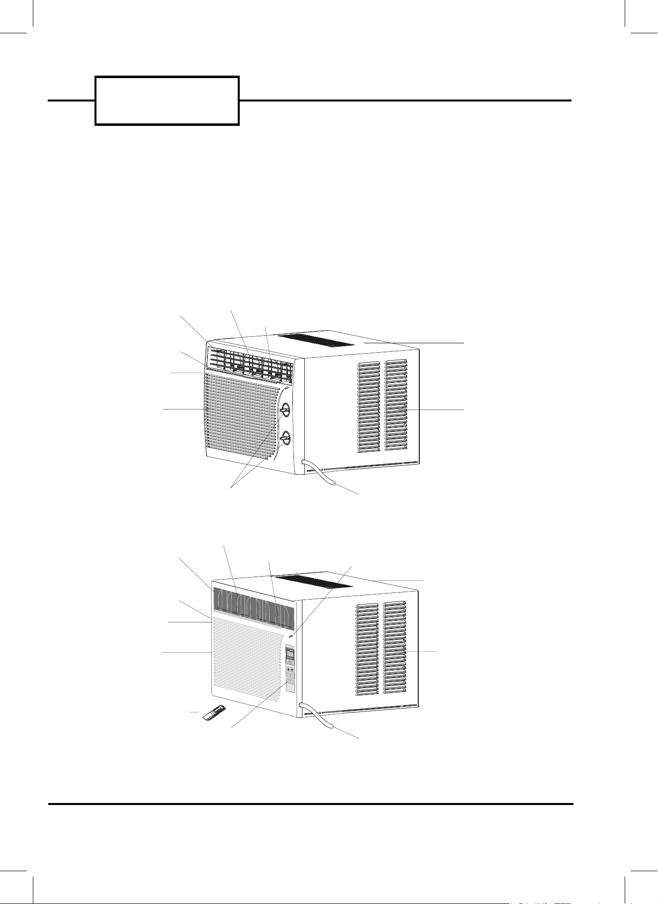
before installing the unit. See Fig. 1 for a part identification and description of the unit.
REQUIRED TOOLS
• Phillips and flathead screwdrivers
• pencil
• level
• measuring tape
• drill
•
1
/8-in. drill bit
• scissors
CABINET
EXTERIOR
AIR INLET
INTERIOR AIR OUTLET
CONTROL KNOBS
POWER CORD
FRONT PANEL
HORIZONTAL AIR VANE
VERTICAL AIR VANE
INTERIOR AIR
INLET GRILLE
AIR FILTER (INSIDE)
CABINET
EXTERIOR
AIR INLET
INTERIOR AIR OUTLET
CONTROL PANEL
POWER CORD
FRONT PANEL
REMOTE CONTROLLER
HORIZONTAL AIR VANE
VERTICAL AIR VANE
EXHAUST AIR LEVER (FOR CA0816KR ONLY)
INTERIOR AIR
INLET GRILLE
AIR FILTER (INSIDE)
FIGURE 1 — AIR CONDITIONER
CA0516K (MECHANICAL CONTROL)
CA0616KR AND CA0816KR (ELECTRONIC CONTROL)
F
H
R
M
O
DE
T
I
M
E
R
F
A
N
S
P
E
E
D
A
i
r
c
o
n
d
i
t
i
o
n
e
r
OFF
ON
/
P2_Owners Guide - 5K,6K, 8K.pdf 30/01/2008 8:38:31 PM

INSTALLATION
INSTALLATION INSTRUCTIONS
Electrical Requirements
EL E C TR IC S H OC K HA ZA RD
• Plug into a grounded 3-prong outlet.
• Do not remove ground prong.
• Do not use an adapter.
• Do not use an extension cord.
• Failure to follow these instructions can
result in death, fire, or electrical shock.
Power Supply Cord
NOTE: Your unit’s device may differ from the one shown.
Unpack the Air Conditioner
EX C E SS IVE W EI GH T HA ZA RD
Use two or more people to move and
install air conditioner.
Failure to do so can result in back or
other injury.
Remove packaging materials
• Remove and properly dispose of packaging materials.
Remove tape and glue residue from surfaces before
turning on the air conditioner. Rub a small amount
of liquid dish soap over the adhesive with your fingers.
Wipe with warm water and dry.
• Do not use sharp instruments, rubbing alcohol,
flammable fluids, or abrasive cleaners to remove
tape or glue. These products can damage the
surface of your air conditioner.
• Handle air conditioner with care.
• The portable air conditioner should be connected
to a 115 V, 60 Hz, 15- or 20-amp fused 3-prong
grounded outlet.
• The use of a time-delay fuse or time-delay circuit
breaker is recommended.
• All wiring must comply with local and national
electrical codes and be installed by a qualified
electrician. If you have any questions, contact
a qualified electrician.
A Reset Button B Test Button
This room air conditioner is equipped with a power supply cord required
by UL. This power supply cord contains state-of-the-art electronics that
sense leakage current. If the cord is crushed, the electronics detect leakage
current and power will be disconnected in a fraction of a second.
Totest your power supply cord:
1. Plug power supply cord into a grounded 3-prong outlet.
2. Press RESET.
3. Press TEST (listen for click; Reset button will trip and pop out).
4. Press and release RESET (listen for click; Reset button will latch
and remain in).The power supply cord is ready for operation.
NOTES:
• The Reset button must be pushed in for proper operation.
• The power supply cord must be replaced if it fails to trip when the
test button is pressed or fails to rest.
• Do not use the power supply cord as as an off/on switch. The
power supply cord is designed as a protective device.
• A damaged power supply cord must be replaced with a new power
supply cord obtained from the product manufacturer and must not
berepaired.
• The power supply cord contains no use serviceable parts. Opening
the tamper-resistant case voids all warranty and performance claims.
3
P3_Owners Guide - 5K,6K, 8K.pdf 30/01/2008 8:41:56 PM
WIRING&LOCATION
Your Climette room air conditioner was designed to be
installed in a single or double hung window. This air
conditioner is not designed for use with vertical (slider
type) windows.
WIRING
The air conditioner is powered by plugging it into a
compatible wall outlet. The electrical outlet MUST
match the plug on the unit power cord. See Table 1 for
receptacle types and fuses. The unit nameplate contains unit electrical data, unit ratings, and identification numbers. The unit nameplate is located on the
right side of the unit. Do not use a plug adapter or an
extension cord.
Check available power supply and resolve any wiring
problems before installing and operating the air conditioner. If wiring is required, all wiring must comply
with all local and national electrical codes. All wiring
must be installed by a qualified electrician. If you have
any questions regarding the unit electrical data or wiring, consult a qualified electrician before installation.
For your safety, this air conditioner is grounded
through the power cord plug when plugged into a
matching wall outlet. The power cord is 60-in. long.
TABLE 1 — RECEPTACLE TYPE AND FUSES
LOCATION
The room air conditioner is designed to fit easily into a
single or double hung window. However, since window
designs vary, it may be necessary to make some modifications for safe and proper installation.
Make sure the window and frame are structurally
sound and free from dry or rotted wood. Replace wood
if necessary or relocate to different window.
For maximum efficiency, install the air conditioner on
the side of the house or building that has more shade
than sunlight.
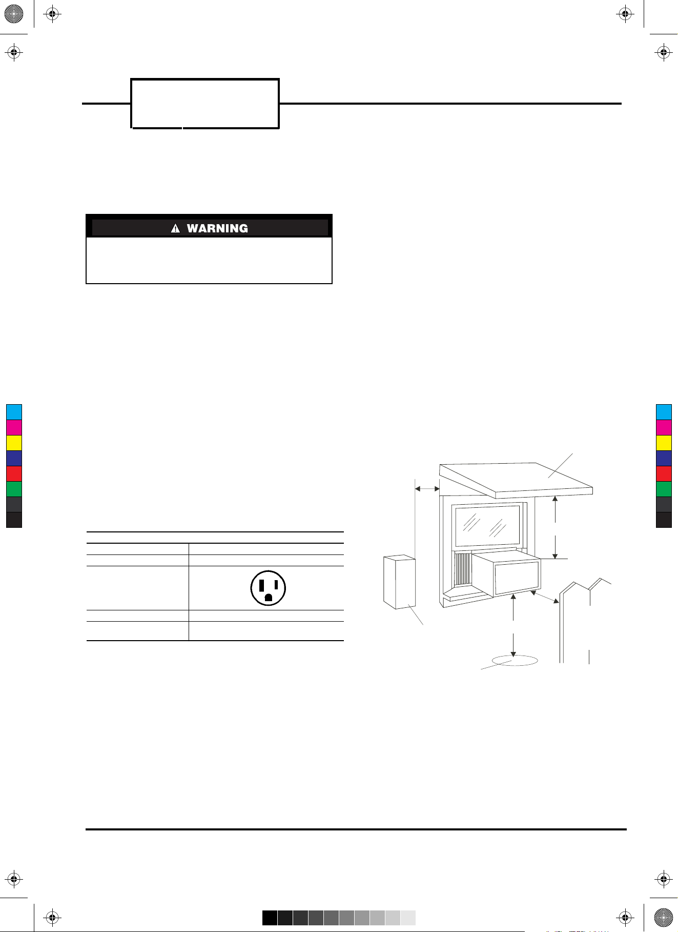
Provide sufficient clearance for the air conditioner to
allow proper air circulation through and around the
unit. The rear of the unit must be outdoors (not in a
garage or inside of the building). Provide 20-in. of
clearance on each side of the unit. Provide 20-in. of
clearance from the rear of the unit to any obstruction.
Provide 12-in. of clearance from the top of the unit. See
Fig. 2.
Unit should be at least 30-in. above the floor and outside ground.
Curtains and other objects should be moved if they
block indoor airflow.
Unit must be within reach of a proper electrical wall
outlet. Do not use an extension cord.
The unit was designed to evaporate condensation
under normal conditions. Under extreme humidity
conditions, excess condensation may cause the
basepan to overflow to the outside of the unit. The unit
should be installed where condensation drip cannot
cause damage.
Electrical shock can cause injury or death. Do not
install unit or remove front grille with the power
cord plugged in. Be sure unit is unplugged before
performing any installation or maintenance.
RECEPTACLE TYPE AND FUSES
VOLTS INDICATED/Hz 125/60
AMPS 15
WALL OUTLET
FUSE SIZE 15
TIME DELAY FUSE
(Circuit Breaker)
Plug Type
AWNING
SIDE
OBSTRUCTION
GROUND
FENCE,
WALL, OR
OTHER
OBSTACLE
12" MIN.
30" MIN.
20"
MIN.
20"
MIN.
FIGURE 2 — AIR CONDITIONER CLEARANCES
CA_
SERIES
4
P4_Owners Guide - 5K,6K, 8K.pdf 30/01/2008 1:01:48 PM
C
M
Y
CM
MY
CY
CMY
K
 Loading...