

Page 1
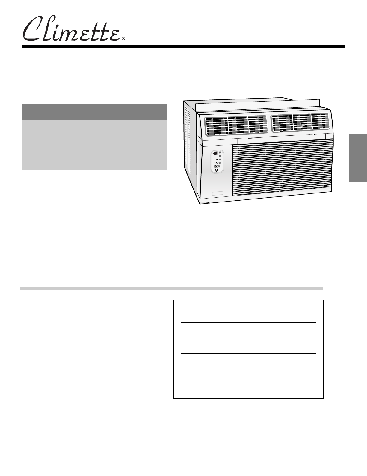
Installation and Operating Instructions
Room Air Conditioners for
Double-Hung Windows & Thru
the wall installation
TABLE OF CONTENTS
ENGLISH
Important Safety Instructions ............................ 1
Installation............................................................2
Operation ............................................................7
Maintenance ........................................................8
How to Obtain Warranty Service or Parts........ 9
E
N
G
L
I
S
H
Keep these instructions for future reference
For additional questions please call
1-217-347-6459
Features and specifications subject to change without notice.
For Future Reference
Write down the model and serial numbers
The model and serial numbers can be found on the side of
the cabinet near the control panel. Use these numbers in
any correspondence or service calls concerning your air
conditioner.
Model Number
Serial Number
Date of Purchase
Page 2
Power Cord with Arc Detection
Device
The power cord supplied with this air
onditioner is equipped with an Arc
c
Detection Device designed to shut off
ower to the unit when it senses an arc
p
fault condition. An arc fault is an
nintentional electrical discharge that
u
occurs when electrical products or wires
are damaged, aged, or improperly used.
An arc fault can be potentially hazardous
if left undetected.
WARNING
• Do not remove or modify this plug
• Do not use as an on/off switch
• Do not use outdoors
Do not push furniture against or place
•
furniture on the electrical cord. This can
trip the test switch and/or damage the
cord and become a potential condition
for arcing
• Do not attempt to repair the cord. If the
cord requires replacement, call an
authorized servicer.
• The Arc Detection Device is not a
Ground Fault Interrupter and should not
be used as such
• The Arc Detection Device contains an
electronic circuit board and should not
be submerged or exposed to water spray
Resetting
If the Arc Detection Device has tripped,
the reset button will pop up.
Follow these steps to reset the Arc
Detection Device:
1. Unplug unit from electrical outlet
2. Press the reset button
3. Plug the unit back into electrical outlet
4. Check to see if power has returned to
the unit
esting
T
ou should test the Arc Detection Device
Y
equipped power cord monthly, after every
major electrical storm, or if power to your
Room Air Conditioner has been
interrupted.
Follow these steps to test the Arc
Detection Device:
Unplug unit from electrical outlet
1.
Press the reset button
2.
3. Plug the unit back into electrical outlet
4. Press test button. Unit should trip and
reset
5. Press reset button again for use
If above test fails, stop using the air
conditioner and contact customer service
by calling the following toll-free number:
1-800-332-6658
button will pop up.
Warning
Electrical Shock Hazard
• Plug unit only into a
grounded electrical outlet.
• Do not use an extension cord or plug
adapter with this unit.
• Do not operate unit with decorative
ront or filter removed.
f
Failure to follow these precautions
•
could result in electrical shock, fire or
personal injury.
• If the air conditioner has a serial plate
rating of 115 volts and greater than 7.5
amps, it must have its own fuse or circuit
breaker, and no other device or unit
should be operated on that fuse or
circuit breaker.
• If the air conditioner has a serial plate
rating of 230 volts, it must have its own
fuse or circuit breaker, and no other
device or unit should be operated on
that fuse or circuit breaker.
• We recommend that a qualified
electrician install unit in accordance
with the National Electrical Code and
local codes and ordinances.
• Use copper conductors of correct wire
gauge and protector size only.
• Do not alter cord or plug end. Do not
remove warning label on cord.
Important Grounding Requirements
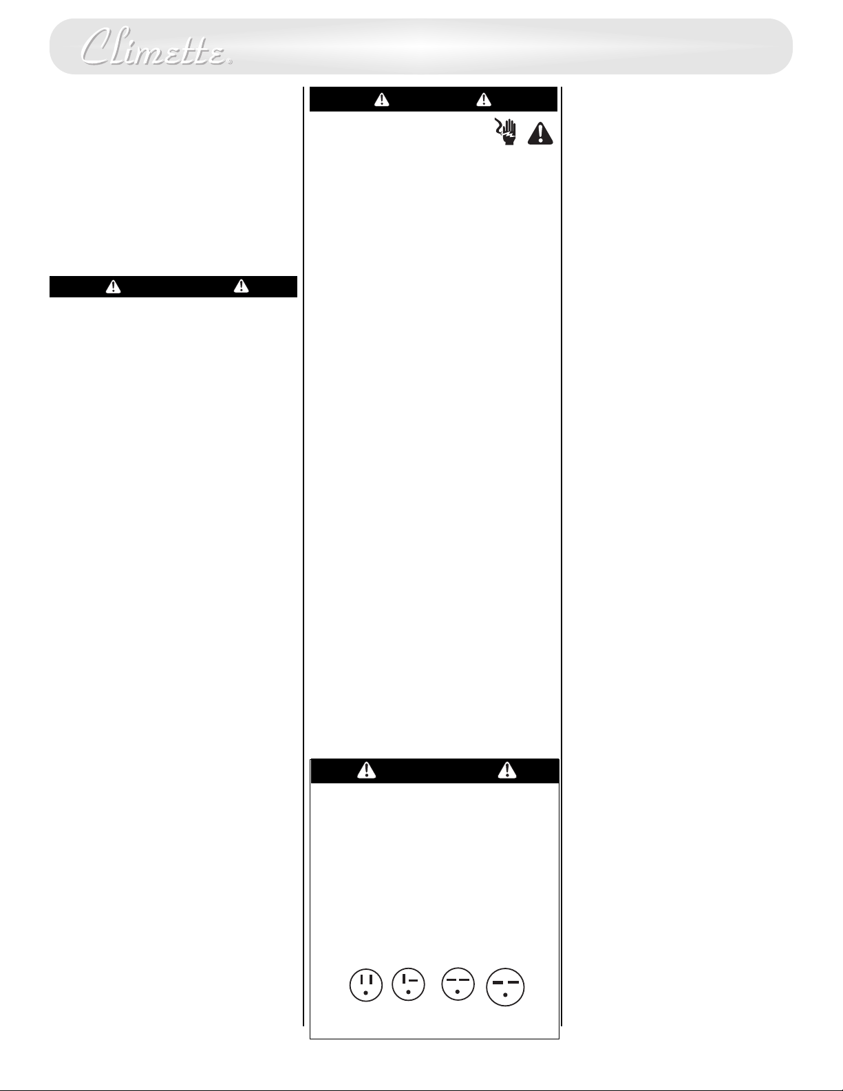
• Air conditioner has a three-prong
grounding plug on the power supply
cord, which must be plugged into a
properly grounded three-prong wall
receptacle for your protection against
possible shock hazard. For models up to
and including 7.5 amperes, use a
grounding type wall receptacle to
match the cord plug.
For models above 7.5 amperes use a
•
single outlet grounding type wall
receptacle to match the cord plug.
Warning
Do not operate this air conditioner
without proper time delay circuit
protection (circuit breaker or fuse).
Refer to serial plate for proper power
supply requirements.
Recommended Wire Sizes
(As installed per building code) :
PROTECTOR SIZEWIRE GAUGE
15 AMP #14 MINIMUM
20 AMP
30 AMP #10 MINIMUM
#12 MINIMUM
Additional Safety Precautions
Do not cut, alter or remove any of
•
the expanded polystyrene
(styrofoam) inside this air
conditioner.
Do not store or use gasoline or
•
ther flammable vapors and
o
liquids in the vicinity of this or any
other appliance. The fumes can
create a fire hazard or explosion.
Do not introduce objects in the air
•
discharge area. This could cause
permanent damage.
• Do not pour liquids on the air
conditioner as this could cause a
malfunction. With the unit
unplugged, use a damp cloth for
cleaning the unit.
• Do not use strong solvents to clean
the air conditioner.
• Clean the air conditioner filter
every two weeks to avoid
overheating caused by air
obstruction. Do not operate
without filter.
• Do not obstruct the air intake area
of your air conditioner, as this
could cause overheating, thus
activating the unit’s security switch
and shutting off the unit.
• Do not block air circulation to
outside louvers of cabinet.
• Do not block air flow inside with
blinds, curtains, or furniture, or
outside with shrubs, enclosures, or
other buildings.
• Do not run the air conditioner with
an outside protective cover in
place. This could result in fire or
mechanical damage within the air
conditioner.
• Depending on the model, your air
conditioner may weigh as much as
95 pounds. T
obtain the necessary help to lift
and position the unit during
installation and removal.
• Handle air conditioner with care.
Wear protective gloves whenever
lifting or carrying the unit.
Carefully inspect the location
•
where the air conditioner will be
installed. Be sure it will support the
weight of the unit over an
extended period of time.
o insure safe handling,
125V
15A
250V
20A
1
250V
15A
250V
30A
Page 3
I
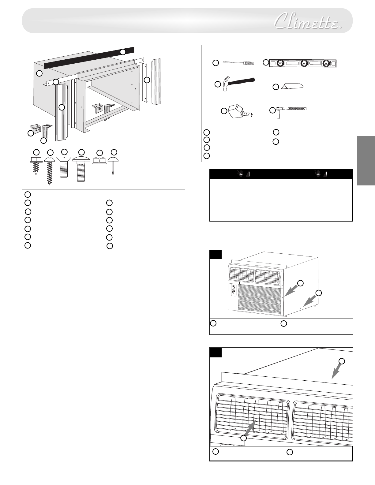
nstallation Parts
G
Tools Needed
A
B
E
F
H
I
Cabinet
A
Sliders
B
Filler panel
C
Side Seal
D
Sill bracket
E
Support bracket
F
Foam
G
A
D
C
J
K
M
L
B
C
A
Blade-type screwdriver
B
Hammer
C
Rule or tape measure
Level
D
D
E
F
E
Knife
Hex driver, ratchet or
F
wrench
E
N
G
L
I
Fasteners:
Hex head screw (6)
H
1” long wood screw (6)
I
5/8” long machine screw (2)
J
Carriage bolt (2)
K
Flange nut (4)
L
Upholsterer’s tack (6)
M
CAUTION
Use two or more people to move and install air
conditioner. Failure to do so can result in injury.
Use caution when working around exposed sharp
edges of the cabinet and sharp coils to avoid injury
or torn clothing.
S
H
1
Window Requirements 28 1/2” to 40” Wide
This air conditioner is factory prepared for installation in
standard double-hung windows with actual opening width of
28 1/2” to 40” and clear, vertical opening of 21” minimum from
bottom of sash to sill.
Note: Unit can be installed in a 27” wide window, if cabinet side seals are
not installed. Use foam seal to fill any openings between the sides of the
cabinet and the window stop molding.
Decorative Front Removal
Detach front panel from cabinet by removing attachment
screws on both sides of unit (Fig. 1).
Removing the Chassis
Remove the two (2) shipping screws from both sides of the
cabinet. Slide the chassis out of the cabinet by pulling the
chassis forward while bracing the cabinet (Fig. 1).
Decorative front
A
retaining screw
2
A
A
Shipping Screw
B
B
B
A
Decorative front Cabinet
B
2
Page 4
Installing Cabinet in Window (Flush Mount)
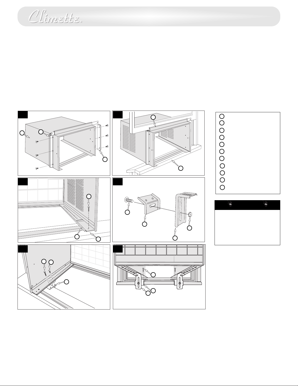
. Attach cabinet side seals to the existing holes in the cabinet
1
using the six (6) screws supplied (Fig. 3).
. Open window and mark the center of window sill. Carefully
2
place cabinet in window and align center mark on the
bottom tie bar with the center mark on the window sill.
3. Close window until it touches behind top retainer bar. Do
not close window so tightly that sliders cannot move. (Do
ot release your grip on the cabinet until the lower
n
window sash is in its final position.) (Fig. 4)
. Attach the cabinet to the window sill by driving two (2) 1”
4
long screws through each cabinet track into the window sill
(Fig. 5).
5. Loosely attach the sill bracket to the support bracket, using
the carriage bolt and flange nut (Fig. 6).
6. Using 5/8” long machine screw and flange nut, attach the
support bracket to the cabinet track. Use the track hole that
ligns with the sill bracket on the outer edge of the window
a
sill (Fig. 7).
. Attach the sill bracket to the window sill using 1” long
7
screws.
8. Tighten the carriage bolt and flange nut. (Fig. 8)
9. Be sure cabinet maintains its outward pitch. This allows air
conditioner to slant slightly downward (1/2 bubble off on a
carpenter’s level) on the outside and prevents water in the
bottom pan from entering the room.
3
A
B
5
F
4
B
C
D
6
Cabinet
A
Cabinet Side seal
B
op retainer bar
T
C
Center of window sill
D
Cabinet Track
E
1” long screw
F
G
Sill Bracket
Carriage bolt
H
I
Support bracket
J
Flange nut
K
5/8” long machine screw
CAUTION
H
G
E
7
D
8
J
I
All supporting parts should be
secured to firm wood,
masonry or metal.
Do not block air circulation to
outside louvers of cabinet.
F
K
J
Installation Other Than Flush Mount
In order to install the unit with more of it projecting into the
room, it will be necessary to relocate the top retaining bar, side
seals and bottom tie bar.
1. Check to make sure the cabinet’s outside side louvers will
not be blocked when the unit is moved farther into the
room.
2. Remove the top retainer bar
tie bar from the cabinet. Relocate them for the desired
, cabinet side seals and bottom
F
G
I
projection into the room.
Using the top retaining bar and cabinet side seals as
3.
templates, locate and drill five (5) 7/32” mounting holes on
the top of the cabinet and three (3) on each cabinet side.
4. Use sealing material to fill the holes in the cabinet top and
sides that become exposed when the top retaining bar and
cabinet side seals were relocated.
Follow all preceding instructions.
5.
3
Page 5
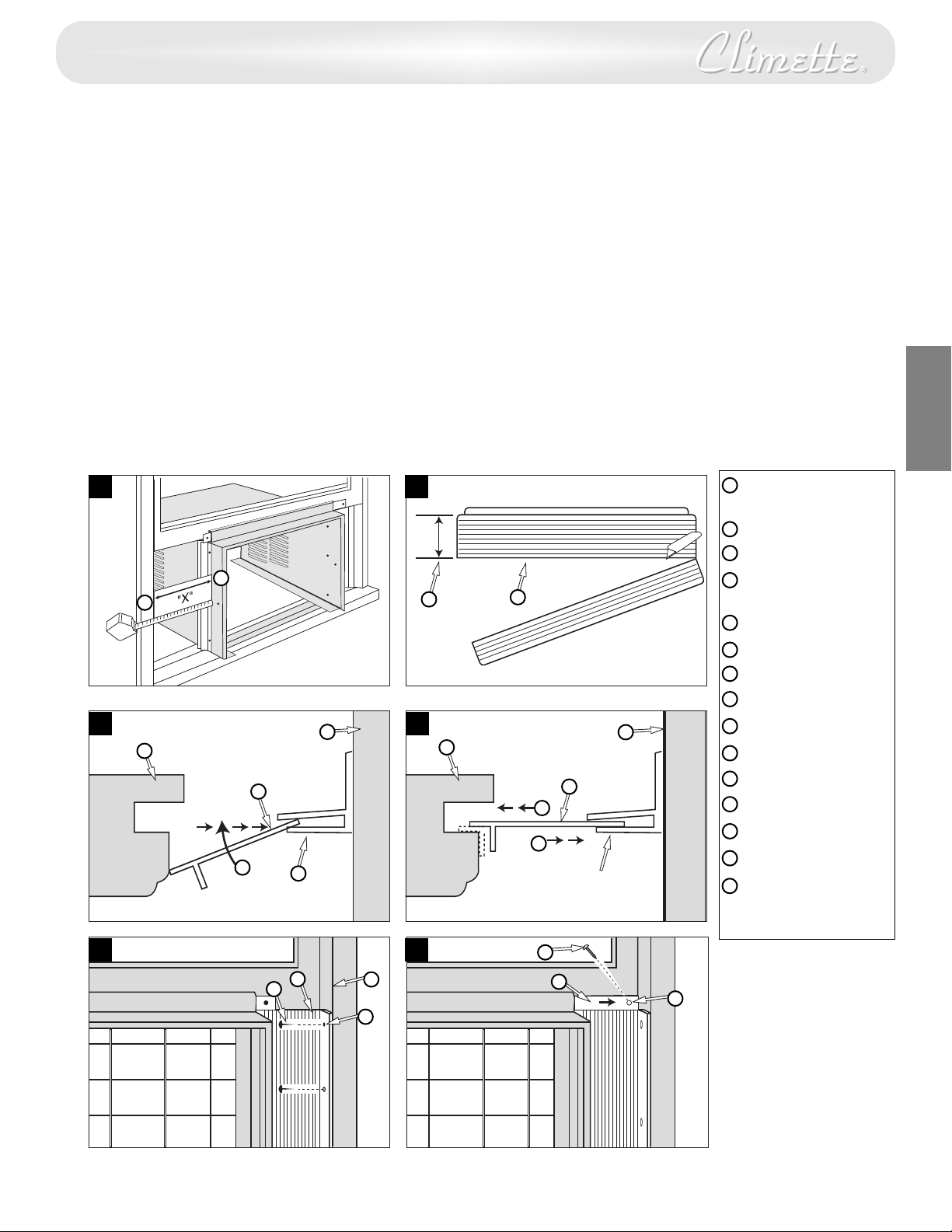
Installing the Window Filler Panels
1. Measure distance “X” between the face of the window stop
molding and the side of the cabinet (Fig. 9).
Note: Measure both sides of unit separately.
2. Subtract one groove (3/16”) from “X” measurement to
btain the required width. Using a sharp knife, score the
o
groove until the filler panel becomes weak enough to break
apart (Fig. 10).
3. Insert cut edge of the filler panel into the cabinet side seal
groove (position 1). Leave a small space at the bottom of the
abinet side seal groove (Fig. 11).
c
Rotate the filler panel backward toward the window frame
until the filler panel clears the window sill. Push the filler
panel down against the window sill (position 2).
Slide the filler panel out from the air conditioner cabinet
until the filler panel flange contacts the window stop
molding (position 3) (Fig. 12).
4. Attach the filler panel to the face of the window stop
molding by driving upholsterers’ tacks through the holes in
11
9
B
A
11 12
G
C
H
F
E
10
D
G
the filler panel flange (Fig. 13).
5. Pull the sliders out until the sliders contact the face of the
window stop molding (Fig. 14).
6. Pull bottom window sash down tightly and lock it in place by
nstalling a 5/8” long screw through the hole in the slider
i
into the window sash (Fig. 14).
. Cut the plastic foam seal to proper length and insert it
7
between the upper and the lower window sash.
Installing the Chassis into the Cabinet
1. Slide the chassis into the cabinet.
. Reattach the screws on both sides of the decorative front.
2
Make sure the power cord aligns with the power cord slot
on the bottom of the decorative front. Make sure the
decorative front is secure before reconnecting the plug and
operating the unit.
4. Cut plastic foam seal to width of window and install
between upper and lower window sash.
5. Use latex or silicone sealant (not supplied) to fi
openings.
Face of window stop
A
molding
Side of cabinet
B
C
Filler Panel
“X” minus one
D
C
F
C
J
I
groove (3/16”)
Cabinet side seal
E
Cabinet
F
G
Window stop
molding
H
Position 1
I
Position 2
J
Position 3
K
Holes in flange
L
Upholsterers’ tacks
M
Hole in slider
N
Slider
O
1” long screw
ll any minor
E
N
G
L
I
S
H
13
14
C
L
G
K
O
N
M
4
Page 6
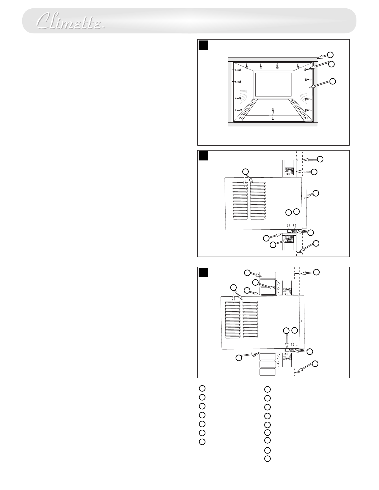
Through-the-wall Installation
This air conditioner is designed as a slide-out type chassis,
making it possible to install it through-the-wall in both existing
and new construction. We recommend that this type of
installation be performed with professional assistance.
• IMPORTANT: This appliance must be installed according to
all applicable electrical and building codes and ordinances.
• It is recommended that you have help to install your unit
and that you use proper lifting technique to avoid personal
injury.
• It is important that you inspect the condition of the wall
where the air conditioner will be installed.
• Be sure the wall can support the weight of the unit.
• All cabinet louvers MUST BE on the outdoor side of the
wall. DO NOT BLOCK SIDE LOUVERS.
• The cabinet must be installed level from side-to-side and
with a downward tilt from inside to outside.
The instructions below are for a typical wall installation. Your
application may vary. Please consult your authorized dealer or
importer before attempting any installation not covered in this
manual.
1. First remove the Decorative front panel and chassis from
the cabinet, then remove top bar from the cabinet.
2. Determine the size of the opening for a wood frame by
adding 1/8” to the width and height of the cabinet.
Measure height from top of cabinet to bottom of bar. Add
this measurement to the thickness of wood used to build
the frame. This will determine the size of wall opening
needed. Minimum 1” thick lumber is recommended when
building the frame. When determining finish frame
thickness, be sure not to cover side louvers on the cabinet.
3. Install the finished frame in the wall opening square and
level, nail or screw it securely to the wall and place the
cabinet into the framed wall opening.
4. Make sure cabinet projects into the roomside of the wall 1
1/4” at the top and 1 1/2” at the bottom to ensure proper
tilt and access to the anti-theft screw, then fasten cabinet to
the frame by drilling twelve (12) 1” wood screws (not
supplied) through the cabinet and into the frame.
If installation is made in a building with brick veneer
construction, a steel angle lintel must be used to support
the bricks above the cabinet.
5. Install a 3/4” X 1 1/2” wood filler strip between the bottom
bar and the interior
strip. After cabinet is installed caulk all openings, inside and
outside between finish frame and cabinet to prevent
moisture from getting to the interior of the wall. Use of
flashing (driprail) will further prevent water from dripping
inside the wall.
6. Install chassis into cabinet.
, caulk both top and bottom of this
15
16
17
O
A
ood frame
W
B
1” wood screws
C
Cabinet
D
Bottom Bar
E
Interior wall
Decorative Front
F
Minimum 1x6 wood
G
support (nailed or
screwed to wood
frame)
A
B
C
J
O
D
G
H
K
L
M
P
D
N
H
K
M
N
O
ood frame
2” W
1 1/2” space
I
1 1/4” space
J
Brick veneer
Lintel angle
L
Caulking
Flashing (drip rail)
Side louvers
P
Wood filler strip
E
F
P
M
I
J
M
I
5
Page 7
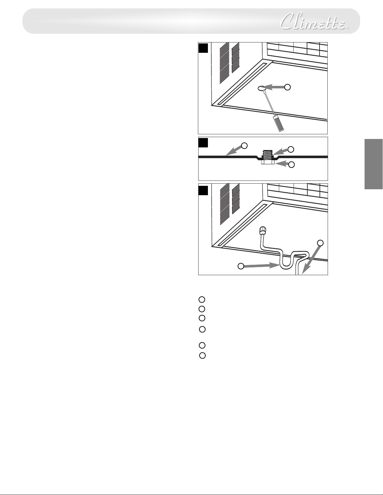
Condensate Drain
A condensate drain is provided to divert excess water when air
onditioner is installed over a doorway or sidewalk.
c
1. Pry cap plug from the condensate drain (located on
nderside of bottom pan). Use a 3/8” pipe tap and fully
u
thread the condensate drain (Fig. 18).
2. Screw a 3/8” pipe fitting into the condensate drain. The
fitting should be protruding approximately 1/2” above the
bottom pan when fully threaded into the condensate drain
(Fig. 19).
3. If an open drain source is used to dispose of condensate,
plastic or rubber tubing may be run directly from the pipe
fitting to the open drain source. If closed drain source
(internal structural plumbing) is used, a “P” trap must be
between the 3/8” pipe fitting and the closed drain source
(Fig. 20).
Consult your authorized dealer or importer for alternative
installation instructions.
Unit is designed to operate with approximately 1/2” of water in
bottom pan.
Do not remove the cap plug, unless the condensate drain is
used.
1
19
22
20
8
A
B
C
D
E
N
G
L
I
S
H
E
Cap plug
A
Bottom pan
B
C
Condensate drain
3/8” pipe fitting fully threaded
D
into condensate drain
“P” trap
E
o closed drain source
T
F
F
6
Page 8
A
AAA
IEC R031.5V
+
-
AAA
IEC R03
1.5V
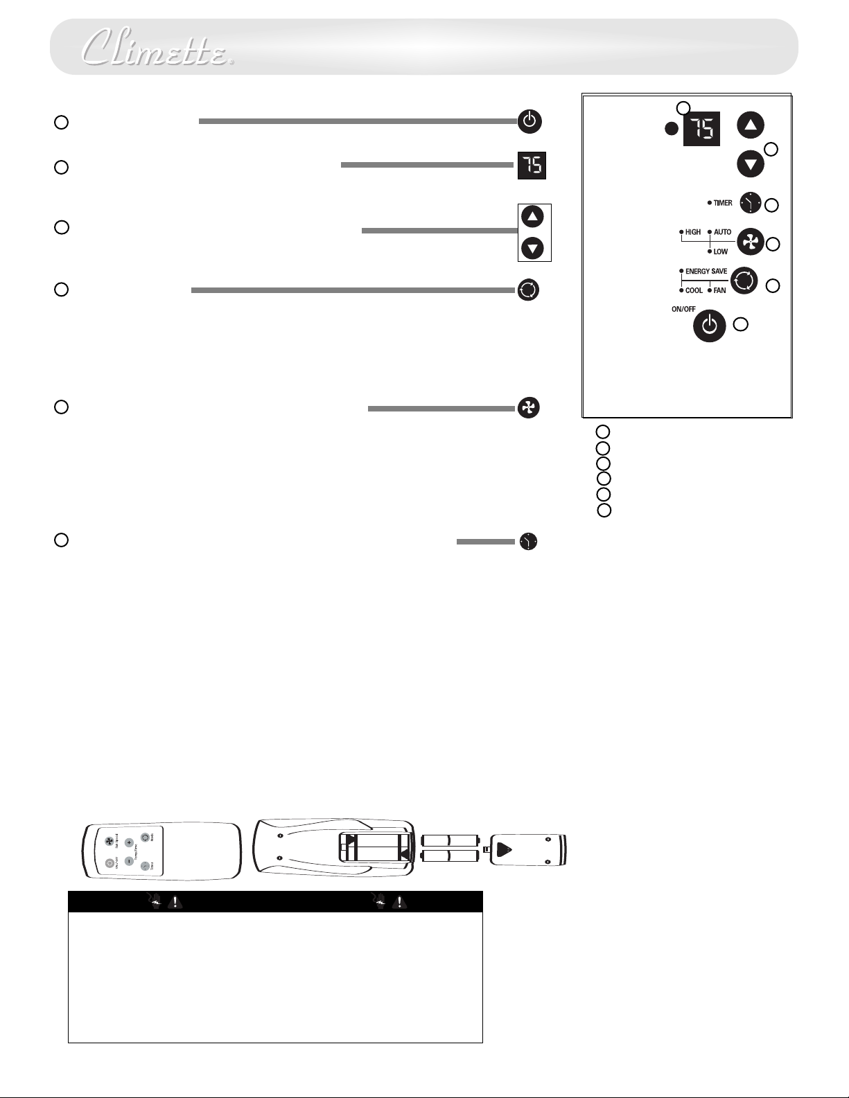
Power Control
The Power Control turns the unit on and off.
Set Temperature/ Timer Display
B
Shows the set temperature when the unit is in operation and hours when the timer
is being set. THE TEMPERATURE DISPLAY ONLY SHOWS THE SET TEMPERATURE, NOT THE
ACTUAL ROOM TEMPERATURE.
C
Temperature/ Timer Hour Controls
These buttons are used to raise or lower the set temperature. By depressing both
buttons at once, the display will toggle between Celsius and Fahrenheit. When the
timer is being set, these buttons are used to change the hour setting in increments
of 1hour from 00 to 24.
D
Mode Control
A green light will indicate which mode is currently being utilized.
ool Mode – The unit will circulate and cool the air.
C
Fan Mode – The unit will only circulate the air.
Energy Saver Mode – The fan will switch from the set fan speed to LOW whenever
the compressor turns off in response to the thermostat. When the compressor cycles
back on, the unit will return to the original fan setting.
E
Fan Speed Control- High, Low, and Auto
The fan speed is adjusted with the Fan Speed Control, each time the button is
depressed it changes the setting. A green light will indicate which setting is
currently being used.
Auto Feature –When the AUTO feature is selected while the air conditioner is in the
COOL mode, the fan speeds will change automatically as the temperature in the
room changes.
• High fan: If the room temperature is 4° or more above the set temperature.
F
• Low fan: If the room temperature is less than 4• above the set temperature.
Timer Control The timer can be set to either turn the unit on or off.
To turn the unit on using the Timer:
Depress the timer key when the power is off, the display will read 00. Adjust to the
desired number of hours before TURN ON using the up/down arrows.
The display will show the time by hours left until TURN ON.
To Turn the timer off, depress the timer key.
A green light next to the Timer Control indicates that the timer is set.
To turn the unit OFF using the Timer:
Depress the timer key when the power is on, the display will read 00. Adjust to the
desired number of hours before TURN OFF using the up/down arrows. The display
will automatically go back to the set temperature after 10 seconds.
To display the amount of time left until TURN OFF, depress the timer button once.
To turn the TIMER OFF, depress the timer button twice.A green light next to the
Timer Control indicates that the timer is set.
B
C
F
E
D
A
ower Control
P
A
Temperature/Timer Display
B
mperature/Timer Controls
Te
C
Mode Control
D
Fan Speed Control
E
Timer On/Off
F
Built-in three minute timing delay.
If this electronic unit will not respond
to touch pad or remote control
commands, it is necessary to unplug
the unit from the electrical outlet for
five seconds and then plug the unit
back in.
Auto restart feature:
In the event of a power failure, this
feature allows the unit to resume
operation once power has been
restored, retaining the most recent
settings. Upon restoration of power,
the timer mode may need to be reset
if being utilized.
Air Conditioner Remote Control
CAUTION
• Use only AAA or IEC R03 1.5V batteries.
• Remove the batteries if the remote controller is not used for a month or
longer.
• Do not attempt to recharge the supplied batteries
• All batteries should be replaced at the same time.
• Do not dispose of the batteries in a fire as they may explode.
• Do not mix old and new batteries.
• Do not install the batteries with the polarity (+/–) reversed.
• Keep batteries and other things that could be swallowed away from
young children. Contact a doctor immediately if an object is swallowed.
7
Page 9
D
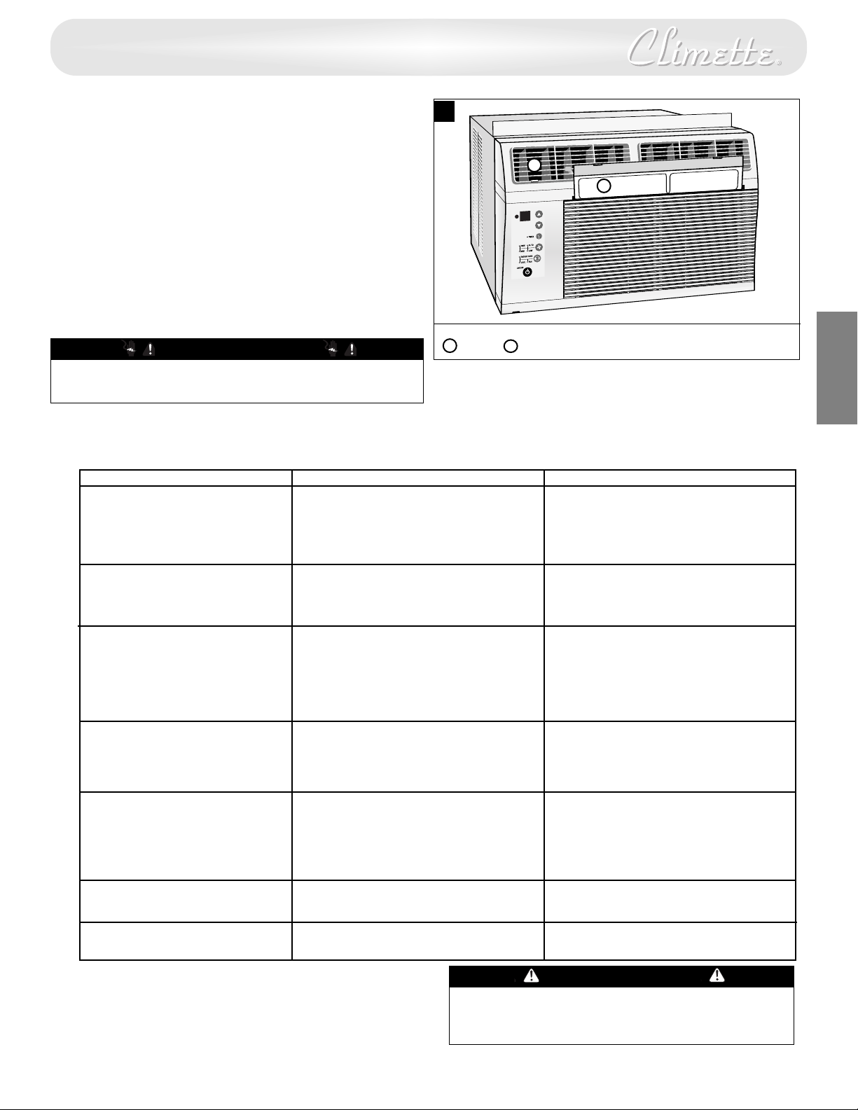
irecting Airflow
Unit is engineered with adjustable louvers to direct discharge
irflow. Louvers are manually adjusted by moving levers in
a
direction of desired airflow (Fig. 21).
Cleaning Air Filter
EVERY TWO WEEKS: Clean the filter.
1. Turn unit off.
. Remove the air filter by grasping the top corners and pulling
2
it up and out of the unit (Fig. 21).
. Wash in hot soapy water, rinse and shake dry.
3
4. Replace the filter, with the front of the filter toward you.
5. To dry the filter thoroughly, run your unit for a few minutes.
Remember, only a clean filter works properly and delivers
top efficiency at every setting.
CAUTION
Failure to keep air fi
operate without fi
lter clean will result in poor air circulation. DO NOT
lter. This can render the unit inoperative.
21
B
A
A
Filter
Proper use and care of your air conditioner will help ensure longer life of the unit.
It is recommended to annually inspect and clean the coils and condensate water
passages. Expense of annual inspection is the consumers’ responsibility
B
ouvers
L
.
E
N
G
L
I
S
H
Troubleshooting Guide
To save time and expense, check the following before calling an authorized servicer.
Occurrence Possible Cause Solutions
Air conditioner will not operate • Wall plug disconnected. • Push plug firmly into wall outlet.
• House fuse blown or circuit breaker tripped. • Replace fuse with time delay type
or reset circuit breaker.
• Unit turned off and then on too quickly. • Wait 3 minutes before restarting.
• Thermostat set too low for cooling. • Adjust thermostat to lower temperature.
Air from unit does not • Unit in Fan mode. • Set Mode to Cool.
feel cold enough • Temperature set too high. • Set thermostat to lower temperature.
• Room temperature below 70°F. • Cooling may not occur until room
temperature rises above 70°F.
Air conditioner cooling, • Outdoor temperature below 70°F. • To defrost the coil, set mode to Fan.
but room is too warm — Then, set thermostat to warmer
temperature.
ice forming on cooling coil • Dirty air filter — air restricted. • Clean filter. See “Cleaning the Air Filter”
section.
behind decorative front To defrost, set mode to Fan.
Air conditioner cooling,
but room too warm —
ice forming on cooling coil
NO
behind decorative front
Noise when unit is cooling • Air movement sound. • The sound of rushing air is normal. If too
loud, Fan Speed to Low setting.
Water dripping inside • Improper installation.
when unit is cooling
ater dripping outside • Unit removing large quantity of moisture
W
when unit is cooling from humid room. days.
• Dirty air fi
• Thermostat set too warm.
• Sound of fan hitting water- • This is normal when humidity is high.
moisture removal system. Close doors, windows and registers.
• Window vibration — poor installation.
lter — air restricted.
• Clean air fi
Refer to “Cleaning Air Filter” section.
• Set thermostat to colder temperature.
• Refer to installation instructions —
check with installer.
• Tilt air conditioner slightly to the outside to
allow water drainage. Refer to installation
instructions — check with installer
• This is normal during excessively humid
lter
.
.
CAUTION
Before cleaning or servicing this unit, it is recommended
that the unit be disconnected from any electrical supply
outlet.
8
Page 10

How to Obtain Warranty Service
Service for your Room Air Conditioner will be provided by
areCo through its network of Authorized Independent
C
Servicers nationwide.
Note: Before calling for service, carefully read the "Installation
nd Operating Instructions" booklet. Then if you need service:
a
1. Call a CareCo authorized service contractor and advise of
he model number, serial number, date of purchase and the
t
nature of your complaint. Service will be provided during
normal working hours. Contact your dealer for the name of
n authorized service contractor, if unknown to you.
a
2. If your dealer is unable to give you the name of a service
contractor or if you need other assistance, call CareCo at
1-800-332-6658
or write:
CareCo
415 Wabash Avenue
Ef
fingham, IL 62401
Proof of Purchase Date
It is the responsibility of the consumer to establish the original
purchase date for warranty purposes. We recommend that a
bill of sale, canceled check or some other appropriate
payment record be kept for that purpose.
9
 Loading...