

Page 1
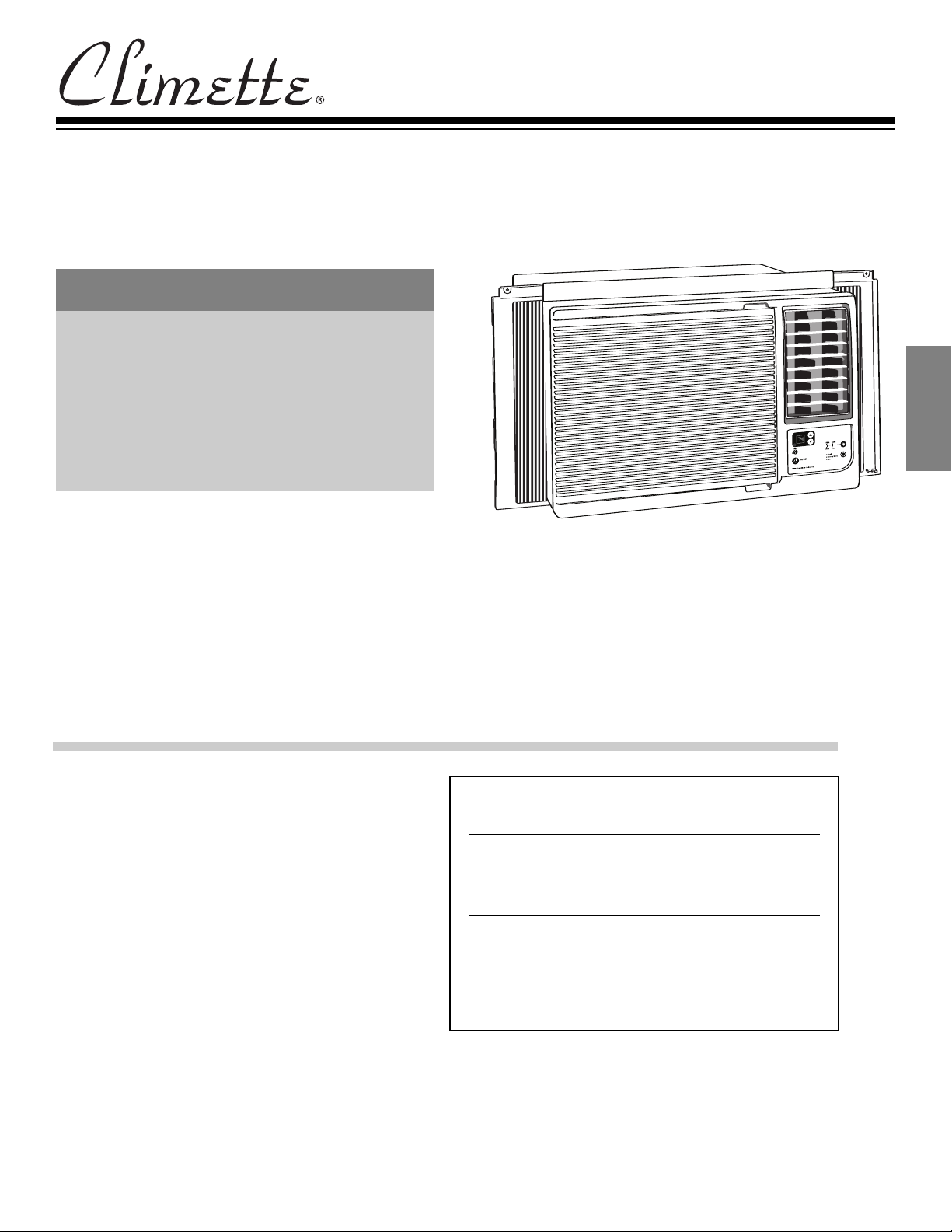
Installation and Operating Instructions
Room Air Conditioners for
Double-Hung Windows & Thru
the wall installation
TABLE OF CONTENTS
ENGLISH
Important Safety Information ................................1
Installation................................................................3
Operation ................................................................6
Maintenance ..........................................................7
roubleshooting ......................................................8
T
How to Obtain Warranty Service or Parts..............9
E
N
G
L
I
S
H
Keep these instructions for future reference
For additional questions please call
1-217-347-6459
Features and specifications subject to change without notice.
For Future Reference
Write down the model and serial numbers
The model and serial numbers can be found on the side of
the cabinet near the control panel. Use these numbers in
any correspondence or service calls concerning your air
conditioner.
Model Number
Serial Number
Date of Purchase
Page 2
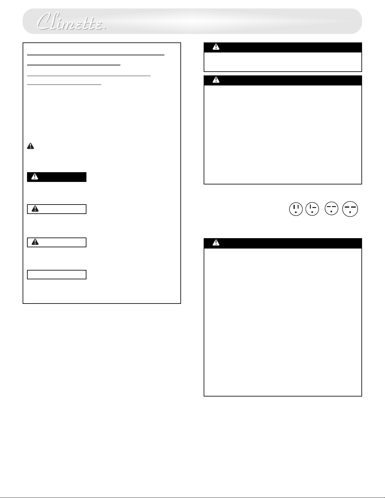
RECOGNIZE SAFETY SYMBOLS,
WORDS AND LABELS
What You Need To Know About
Safety Instructions
Warning and Important Safety Instructions appearing in
this manual are not meant to cover all possible
onditions and situations that may occur. Common
c
ense, caution and care must be exercised when
s
operating or cleaning tools and equipment.
Always contact your dealer, distributor, service agent or
manufacturer about problems or conditions you do not
understand.
This is the safety alert symbol. It is used to alert you
to potential personal injury hazards. Obey all safety
messages that follow this symbol to avoid possible
injury or death.
DANGER
DANGER indicates an imminently hazardous situation
which, if not avoided, will result in death or serious
injury.
WARNING
WARNING indicates a potentially hazardous situation
which, if not avoided, could result in death or serious
injury.
ANGER
D
Do not store or use gasoline or other flammable vapors
and liquids in the vicinity of this or any other appliance.
The fumes can create a fire hazard or explosion.
ANGER
D
Important Grounding Requirements
• Air conditioner has a three-prong grounding plug
on the power supply cord, which must be plugged
nto a properly grounded three-prong wall
i
receptacle for your protection against possible
hock hazard. For models up to and including 7.5
s
amperes, use a grounding type wall receptacle to
match the cord plug.
• For models above 7.5 amperes use a single outlet
grounding type wall receptacle to match the cord
plug.
Do not operate this air conditioner without proper
time delay circuit protection (circuit breaker or fuse).
Refer to serial plate for proper power supply
requirements.
Recommended Wire Sizes
(As installed per building code) :
PROTECTOR SIZEWIRE GAUGE
15 AMP #14 MINIMUM
20 AMP #12 MINIMUM
30 AMP #10 MINIMUM
125V
15A
250V
20A
250V
15A
250V
30A
CAUTION
CAUTION indicates an potentially hazardous situation
which, if not avoided, may result in minor or moderate
injury.
CAUTION
CAUTION used without the safety alert symbol
indicates a potentially hazardous situation which, if not
avoided, may result in property damage.
DANGER
Electrical Shock Hazard
• Plug unit only into a grounded electrical outlet.
• Do not use an extension cord or plug adapter with
this unit. Do not alter cord or plug end. Do not
remove warning label on cord.
• Do not operate unit with decorative front or filter
removed.
• If the air conditioner has a serial plate rating of 115
volts and greater than 7.5 amps, it must have its
own fuse or circuit breaker, and no other device or
unit should be operated on that fuse or circuit
breaker.
• If the air conditioner has a serial plate rating of 230
volts, it must have its own fuse or circuit breaker,
and no other device or unit should be operated on
that fuse or circuit breaker.
e recommend that a qualified electrician install
• W
unit in accordance with the National Electrical Code
and local codes and ordinances.
• Use copper conductors of correct wire gauge and
protector size only
.
1
1
Page 3
Power Cord with
Arc Detection Device
The power cord supplied with this air conditioner is
equipped with an Arc Detection Device designed to shut
ff power to the unit when it senses an arc fault condition.
o
An arc fault is an unintentional electrical discharge that
ccurs when electrical products or wires are damaged,
o
aged, or improperly used. An arc fault can be potentially
azardous if left undetected.
h
DANGER
• Do not remove or modify this plug
Do not use as an on/off switch
•
•
Do not use outdoors
Do not push furniture against or place furniture on the
•
electrical cord. This can trip the test switch and/or
damage the cord and become a potential condition
for arcing
Do not attempt to repair the cord. If the cord requires
•
replacement, call an authorized servicer.
• The Arc Detection Device is not a Ground Fault
Interrupter and should not be used as such
• The Arc Detection Device contains an electronic circuit
board and should not be submerged or exposed to
water spray
Resetting
If the Arc Detection Device has tripped, the reset
button will pop up.
Follow these steps to reset the Arc Detection Device:
1. Unplug unit from electrical outlet
2. Press the reset button
3. Plug the unit back into electrical outlet
4. Check to see if power has returned to the unit
Testing
You should test the Arc Detection Device equipped
power cord monthly, after every major electrical storm,
or if power to your Room Air Conditioner has been
interrupted.
Follow these steps to test the Arc Detection Device:
1. Unplug unit from electrical outlet
2. Press the reset button
Plug the unit back into electrical outlet
3.
4. Press test button. Unit should trip and reset button will
pop up.
5.
Press reset button again for use
ARNING
W
Use two or more people to move and install air
conditioner. Failure to do so can result in back or
other injury.
CAUTION
• Do not cut, alter or remove any of the expanded
polystyrene (styrofoam) inside this air conditioner.
Do not introduce objects in the air discharge area. This
•
could cause permanent damage.
•
Do not pour liquids on the air conditioner as this could
cause a malfunction. With the unit unplugged, use a
damp cloth for cleaning the unit.
CAUTION
• Do not use strong solvents to clean the air conditioner.
• Clean the air conditioner filter every two weeks to
avoid overheating caused by air obstruction. Do not
operate without filter.
Do not obstruct the air intake area of your air
•
conditioner, as this could cause overheating, thus
activating the unit’s security switch and shutting off the
unit.
Do not block air circulation to outside louvers of
•
cabinet.
Do not block air flow inside with blinds, curtains, or
•
furniture, or outside with shrubs, enclosures, or other
buildings.
•
Do not run the air conditioner with an outside
protective cover in place. This could result in fire or
mechanical damage within the air conditioner.
• Carefully inspect the location where the air conditioner
will be installed. Be sure it will support the weight of
the unit over an extended period of time.
E
N
G
L
I
S
H
If above test fails, stop using the air conditioner and
contact customer service
free number:
1-866-629-8441
by calling the following toll-
2
2
Page 4
Installation
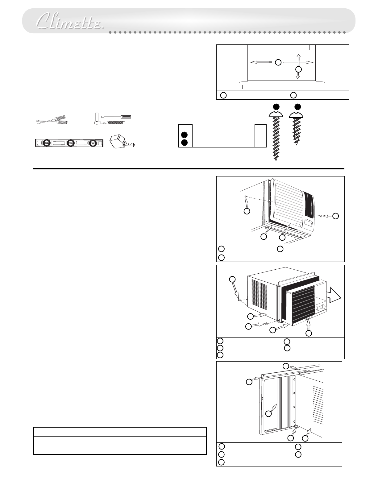
indow Requirements:
W
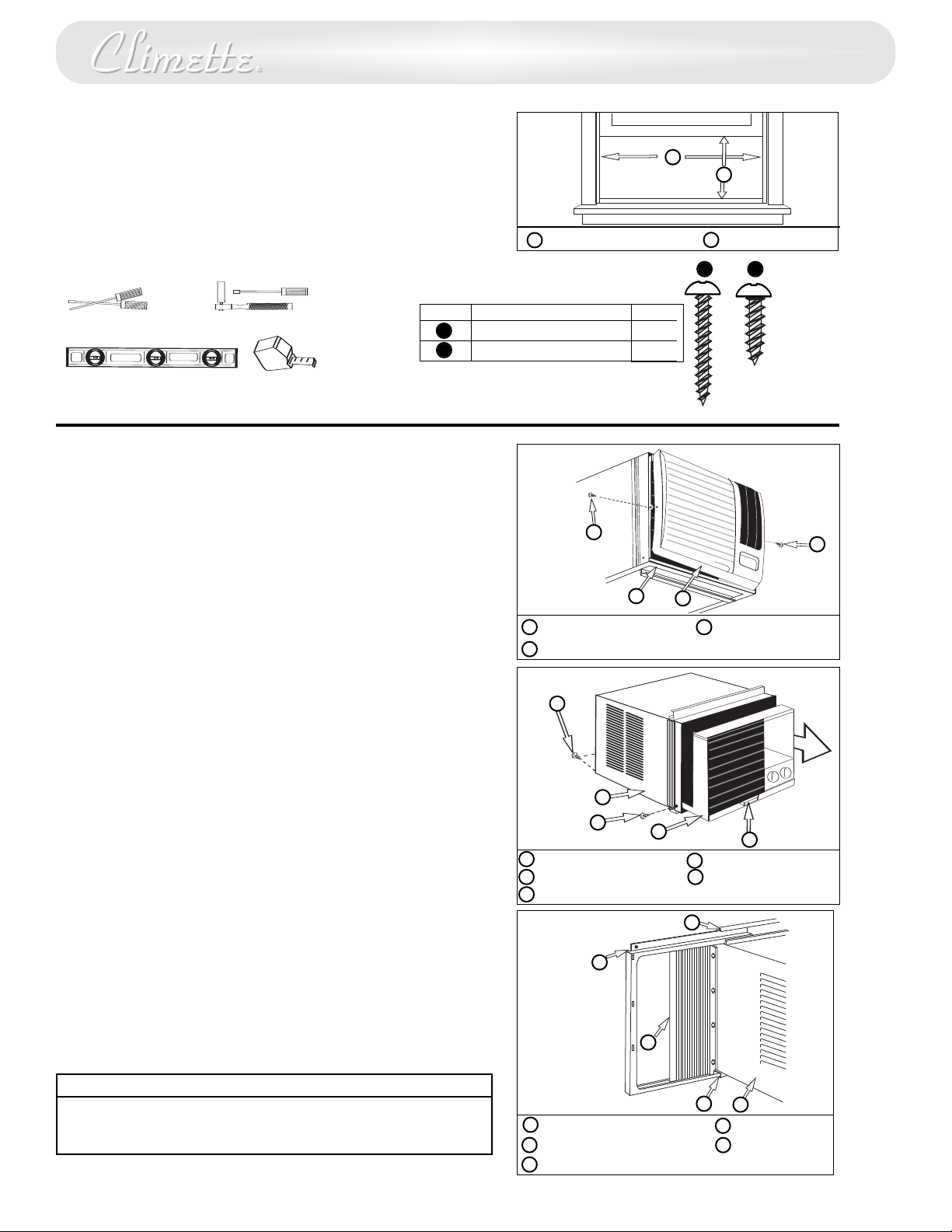
This air conditioner is factory prepared for installation in standard
double-hung windows with actual opening width of 26 7/8” to 41
/8” and clear, vertical opening of 15 5/8” minimum from bottom
5
of sash to sill. Unit can be installed in 23 7/8” wide window, if
cabinet side seals are removed.
A
B
Tools Needed
Fastener Identification
Installation Parts Kit contents:
tem
crewdrivers
S
Carpenter’s Level
atchet or Driver with 1/4” socket
R
Tape Measure
I
A
B
Window Installation
Decorative Front Removal
1. Remove the 3/8” phillips screws on either side of the cabinet
2. Gently pull forward while grasping both sides of the decorative
front.
Removing the Chassis
1. Remove the two (2) shipping screws from the rear bottom side
of the cabinet. These shipping screws may be discarded.
23 7/8” to 41 5/8”
A
Description
1” wood screw
5/8” wood screw
Cabinet
A
Decorative Front
B
A
15 5/8” minimum
B
A B
ty
Q
1
4
Actual size
C
A
B
3/8” phillips screw
C
C
2. Remove the two (2) antitheft screws from the bottom front
sides of the cabinet. RETAIN THESE SCREWS, they will be
replaced later in the installation.
3. Slide the chassis out of the cabinet by grasping the base pan
handle and pulling forward while bracing the top bar.
Filler Panel Frame Installation
1. Slide the filler panel frame onto the air conditioner cabinet using
the tracks on the top bar and bottom bar of the unit. Slide the
frame as close to the air conditioner as possible so that the curtain
locks into place.
2. Gently pull the frame out until it is the correct length for
your application.
CAUTION
Use caution when working around exposed sharp edges of the
cabinet and sharp coils to avoid injury or torn clothing.
3
3
B
C
Shipping Screws
A
Cabinet
B
Anti-theft screws
C
B
op Bar
T
A
Filler Panel Frame
B
Filler Panel Locking Edge
C
D
C
E
Chassis
D
Base pan handle
E
A
D
E
Bottom Bar
D
Cabinet
E
Page 5
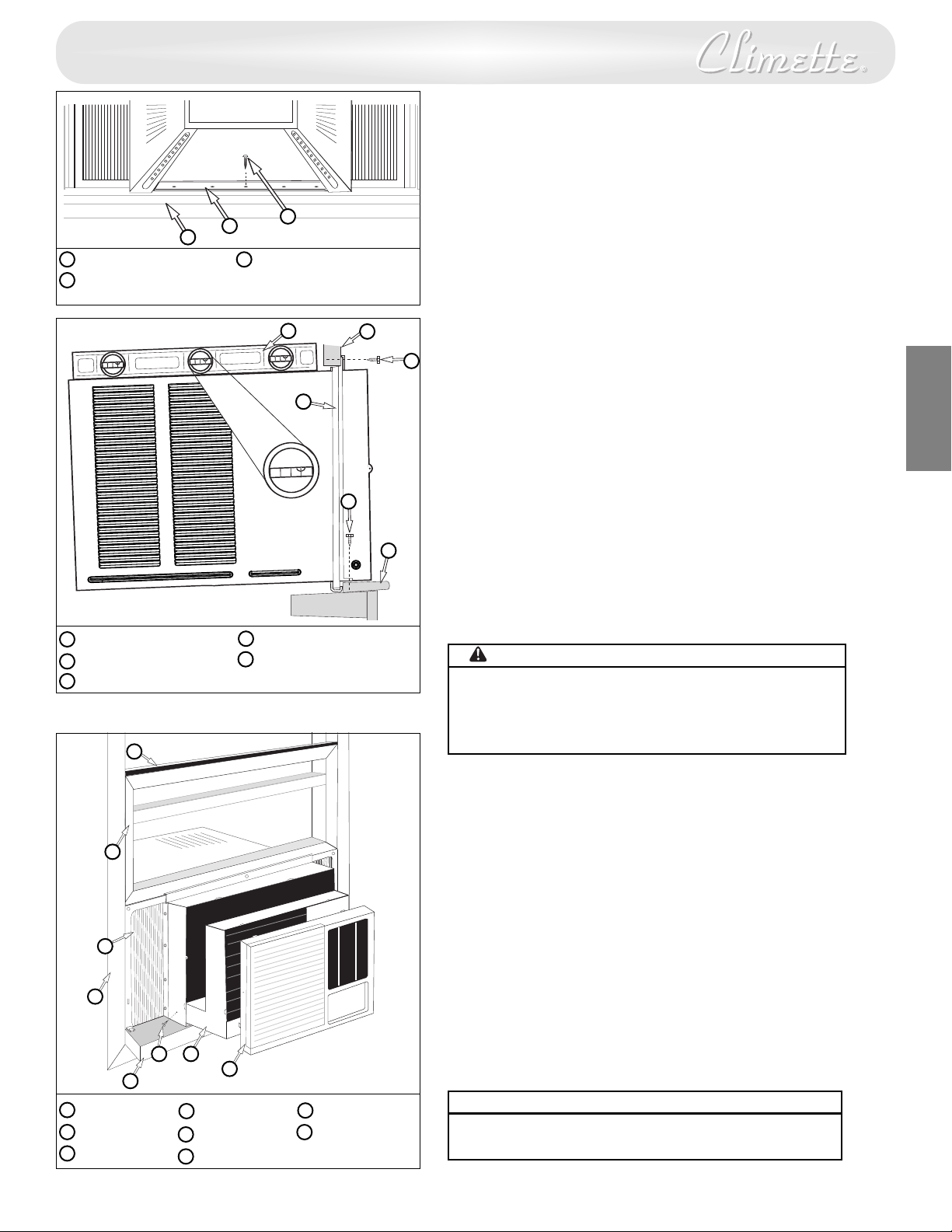
Window Installation (cont.)
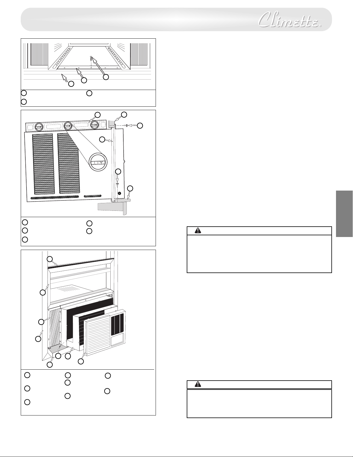
1. Open window, by raising lower window sash, and
ark the center of window sill. Carefully place
m
abinet in window and align center hole on the
c
ottom bar with the center mark on the window sill.
b
Window sill
A
Bottom Bar
B
Side View
Carpenter’s Level
A
Window sash
B
Filler Panel
C
A
B
C
D
B
A
C
1” Wood Screw
C
A
C
B
D
D
top bar. (Do not release your grip on the cabinet until
the lower window sash is in its final position).
3. Attach the cabinet to the window sill by driving one 1”
ong wood screw through the bottom bar into the
l
indow sill.
w
Be sure cabinet maintains an downward pitch. Air
conditioner should slant slightly downward on the
outside as shown by 1/2 a bubble off on a carpenter’s
level. This outward pitch prevents water from
entering the room.
Securing the Filler Panels
4. Slide filler panels outward until they touch window
sash tracks.
5. Secure top of filler panels by driving a 5/8” wood
screw through each top mounting hole into
E
N
G
L
I
S
H
window sash.
2. Close lower window sash until it touches behind the
E
6. Secure bottom of filler panels by driving a 5/8”
wood screw into window sill through each filler
panel tab.
7. Install chassis into cabinet.
5/8” wood screw
D
Window sill
E
WARNING
Do not obstruct the air intake area of your air conditioner, as
this could cause overheating, thus activating the units
security switch and shutting off the unit. Do not block aiflow
inside with blinds, curtains, or furniture. Do not block airflow
outside with shrubs, enclosures, or other buildings.
Installing the Chassis into the Cabinet
1. Slide the chassis into the cabinet.
2. Replace the two anti-theft screws at the bottom
front sides of cabinet.
3. To replace the decorative front, line up the top tabs
and and sides, and gently press into position.
Reattach the screws on both sides of the decorative
front. Make sure the power cord aligns with the
power cord slot on the bottom of the decorative
front. Make sure the decorative front is secure
before reconnecting the plug and operating the
unit.
4. Cut plastic foam seal to width of window and install
between upper and lower window sash.
A
Foam Seal
Lower sash
B
C
Filler panel
Use latex or silicone sealant (not supplied) to fill any
G
F
E
H
Molding
D
Window Sill
E
Anti-Theft screw
F
G
H
Chassis
Dec front
5.
minor openings.
CAUTION
Do not drill a hole in the bottom pan. Unit is designed to
operate with approximately 1/2” of water in bottom pan.
4
4
Page 6
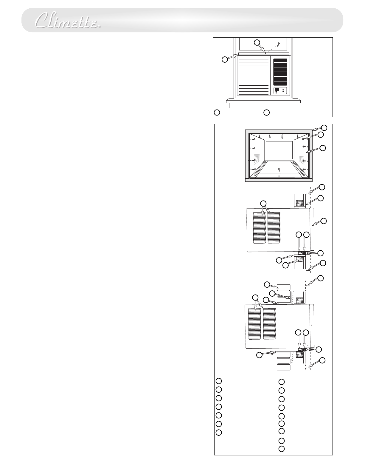
Installing Cabinet in Minimum Width Window
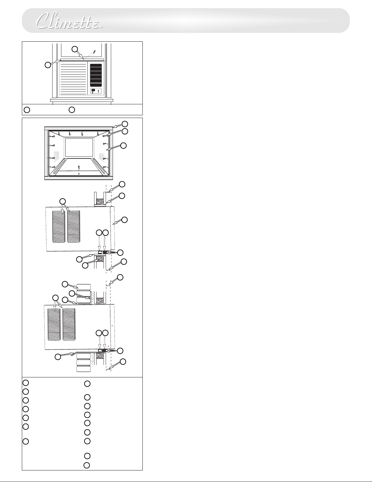
1. Remove filler panels on air conditioner cabinet.
2. Refer to steps 1 through 3 of Window Installation instructions.
3. Close window until it touches behind air conditioner top bar.
4. Fasten top bar to window frame using 5/8” washer head screw.
5. If filler is required on sides of air conditioner, cut plastic foam
seal to size and fill both sides.
6. Use silicone or latex sealant (not supplied to fill any minor
openings.
7. Install chassis into cabinet.
B
A
Consult your authorized dealer or importer for alternative
installation instructions.
Through-the-wall Installation
This air conditioner is designed as a slide-out type chassis, making it
possible to install it through-the-wall in both existing and new
construction. We recommend that this type of installation be
performed with professional assistance.
• IMPORTANT:
applicable electrical and building codes and ordinances.
• It is recommended that you have help to install your unit and that
you use proper lifting technique to avoid personal injury.
• It is important that you inspect the condition of the wall where
the air conditioner will be installed.
• Be sure the wall can support the weight of the unit.
• All cabinet louvers MUST BE on the outdoor side of the wall. DO
NOT BLOCK SIDE LOUVERS.
• The cabinet must be installed level from side-to-side and with a
downward tilt from inside to outside.
1. First remove the Decorative front panel and chassis from the
cabinet, then remove top bar from the cabinet.
2. Determine the size of the opening for a wood frame by adding
1/8” to the width and height of the cabinet. Measure height
from top of cabinet to bottom of bar. Add this measurement to
the thickness of wood used to build the frame. This will
determine the size of wall opening needed. Minimum 1” thick
lumber is recommended when building the frame. When
determining finish frame thickness, be sure not to cover side
louvers on the cabinet.
This appliance must be installed according to all
Top Bar Attach top bar here
A
B
Fig. 1
O
Fig. 2
G
K
L
O
M
D
P
H
A
B
C
J
E
F
M
I
J
3. Install the finished frame in the wall opening square and level,
nail or screw it securely to the wall and place the cabinet into
the framed wall opening.
4. Make sure cabinet projects into the roomside of the wall 1
1/4” at the top and 1 1/2” at the bottom to ensure proper tilt
and access to the anti-theft screw, then fasten cabinet to the
frame by drilling twelve (12) 1” wood screws (not supplied)
through the cabinet and into the frame. (Fig. 1 &2)
If installation is made in a building with brick veneer
construction, a steel angle lintel must be used to support the
bricks above the cabinet.(Fig.3)
Install a 3/4” X 1 1/2” wood filler strip between the bottom bar
5.
and the interior, caulk both top and bottom of this strip. After
cabinet is installed caulk all openings, inside and outside
between finish frame and cabinet to prevent moisture from
getting to the interior of the wall. Use of flashing (driprail) will
further prevent water from dripping inside the wall.
6. Install chassis into cabinet.
5
5
Fig. 3
A
Wood frame
B
1” wood screws
C
Cabinet
D
Bottom Bar
E
Interior wall
Decorative Fr
F
Minimum 1x6 wood
G
support (nailed or
ewed to wood
scr
frame)
N
ont
D
P
H
2” Wood frame
1 1/2” space
I
1 1/4” space
J
Brick veneer
K
Lintel angle
L
M
Caulking
N
Flashing (drip rail)
Side louvers
O
P
ood filler strip
W
M
I
Page 7
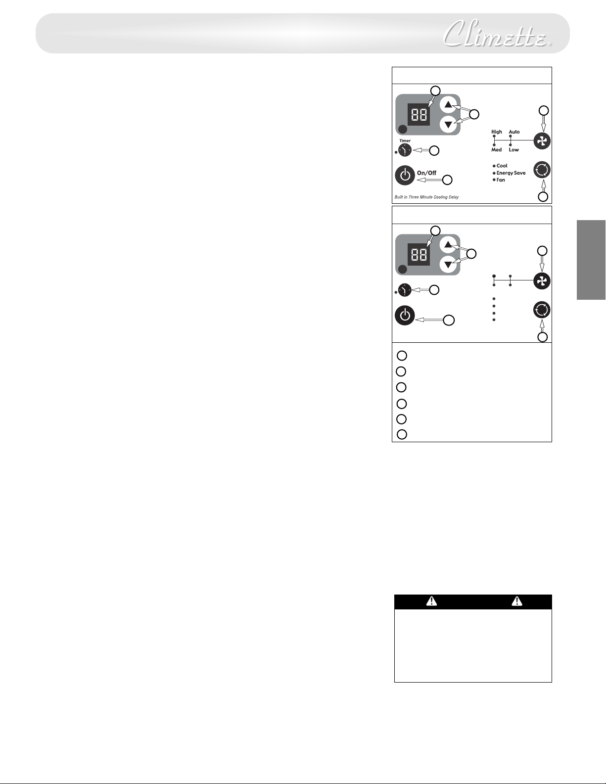
Built in Three Minute Cooling Delay
Cool
High
Timer
M
ed
Auto
L
ow
Fan
E
nergy Save
H
eat
On/Off
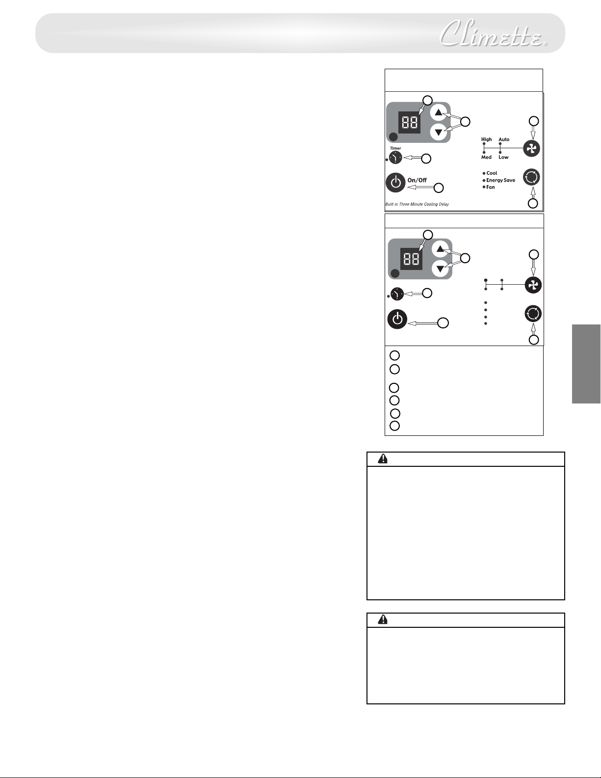
Power Control
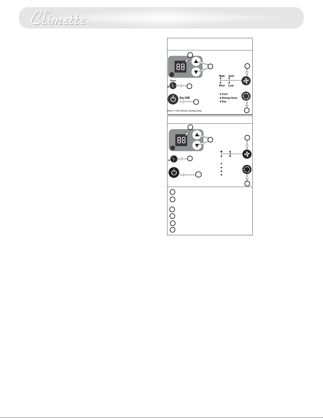
The Power Control turns the unit on and off.
Set Temperature/ Timer Display
Shows the set temperature when the unit is in operation and hours when the
timer is being set. THE TEMPERATURE DISPLAY ONLY SHOWS THE SET
TEMPERATURE, NOT THE ACTUAL ROOM TEMPERATURE.
Temperature/ Timer Hour Controls
These buttons are used to raise or lower the set temperature in increments of 1°
from 66°F to 88°F. By depressing both buttons at once, the display will toggle
between Celsius and Fahrenheit. When the timer is being set, these buttons are
used to change the hour setting in increments of 1 from 00 to 24.
Mode Control
A green light will indicate which mode is currently being utilized.
Cool Mode –
The unit will circulate and cool the air.
Heat Mode (Heat Models Only) –
The unit will circulate and heat the air.
Heater Safety Feature- When heater is powered off, low fan will automatically stay on
and run for 60 seconds to ensure the removal of residual heat, meanwhile, the Low Fan
LED blinks until the low fan stops.
Fan Mode –
The unit will only circulate the air.
Energy Saver Mode –
(The energy saver mode is designed to operate with Cool mode only). The fan will
switch from the set fan speed to Low whenever the compressor turns off in
response to the thermostat. When the compressor cycles back on, the unit will
return to the original fan setting. Speeds will change automatically as the
temperature in the room changes.
Fan Speed Control - High, Medium, Low and Auto
The settings are adjusted with the Fan Speed Control, each time the button is
depressed it changes the setting. A green light will indicate which setting is
currently being used.
When the Auto feature is selected while the air conditioner is in the Cool or Heat
mode, the fan speeds will change automatically as the temperature in the room
changes. In Cool Mode when the room reaches 7° or more above the set
temperature High Fan will be used, 4° or less above the set temperature will use
Low fan. In Heat Mode when the room reaches 7
temperature High fan will be used, 4
° or less below the set temperature will use
° or more below the set
Low fan. At all other times the fan will use Medium fan.
Timer Control (The timer can be set to either turn the unit on or off.)
To automatically START the unit using the Timer mode:
1. Push the timer button while the power is OFF. The display will read 00. Adjust
the display to show the desired number of hours before ST
emperature/Timer adjustment arrows.
T
The display will show the amount of time, in hours, remaining until ST
2.
.
UP
o exit T
T
3.
4.
A green light next to the Timer button indicates that the timer is set.
To automatically SHUT-DOWN the unit using the Timer mode:
imer mode, push the Timer button.
1. Push the timer button while the power is ON. The display will read 00.
Adjust the display to show the desired number of hours before SHUT-DOWN
using the Temperature/Timer adjustment arrows. (The display will
automatically return to the set temperature after 10 seconds.)
2. To display the amount of time left until SHUT-DOWN, push the Timer button
once.
3. To exit Timer mode, push the Timer button twice.
4. A green light next to the Timer button indicates that the timer is set.
AR
6
-UP using the
T
AR
6
Electronic Control (Cooling Only)
A
B
C
F
D
E
Electronic Control (Heat/Cool)
A
B
D
E
N
G
L
I
S
C
F
Temperature/Timer Display
A
Temperature/Timer Adjustment
B
Timer On/Off
C
Fan Speed Control
D
Mode Control
E
Power Control
F
E
H
Built-in three minute timing delay.
If this electronic unit will not respond
to touch pad or remote control
commands, it is necessary to unplug
the unit from the electrical outlet for
five seconds and then plug the unit
back in.
Auto restart feature:
In the event of a power failure, this
feature allows the unit to resume
operation once power has been
restored, retaining the most recent
settings
-
T
WARNING
Heat/Cool models or units with
electric heat are designed to be
used only as a supplemental heat
source. They should be used in
addition to regular heating systems
and never as the primary source of
heat.
Page 8
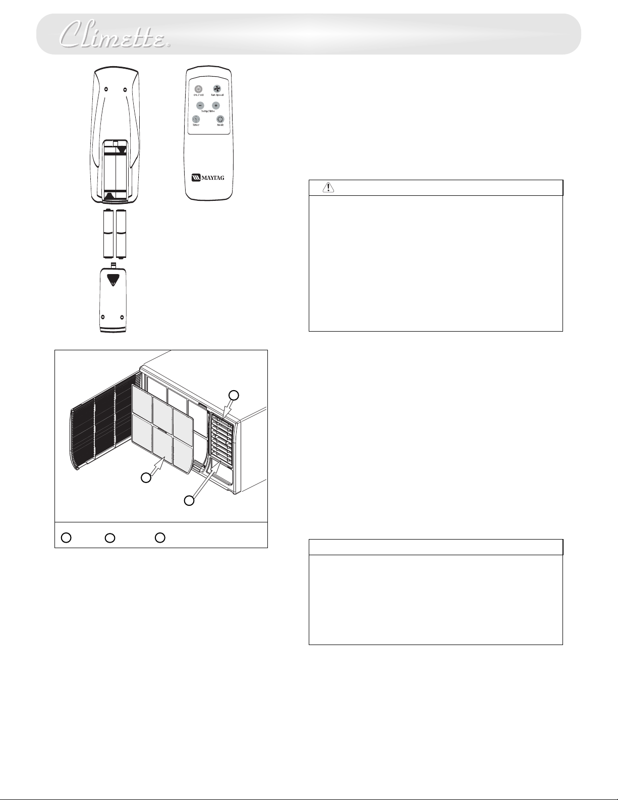
Air Conditioner Remote Control
AAA
IEC R031.5V
+
-
AAA
IEC R03
1.5V
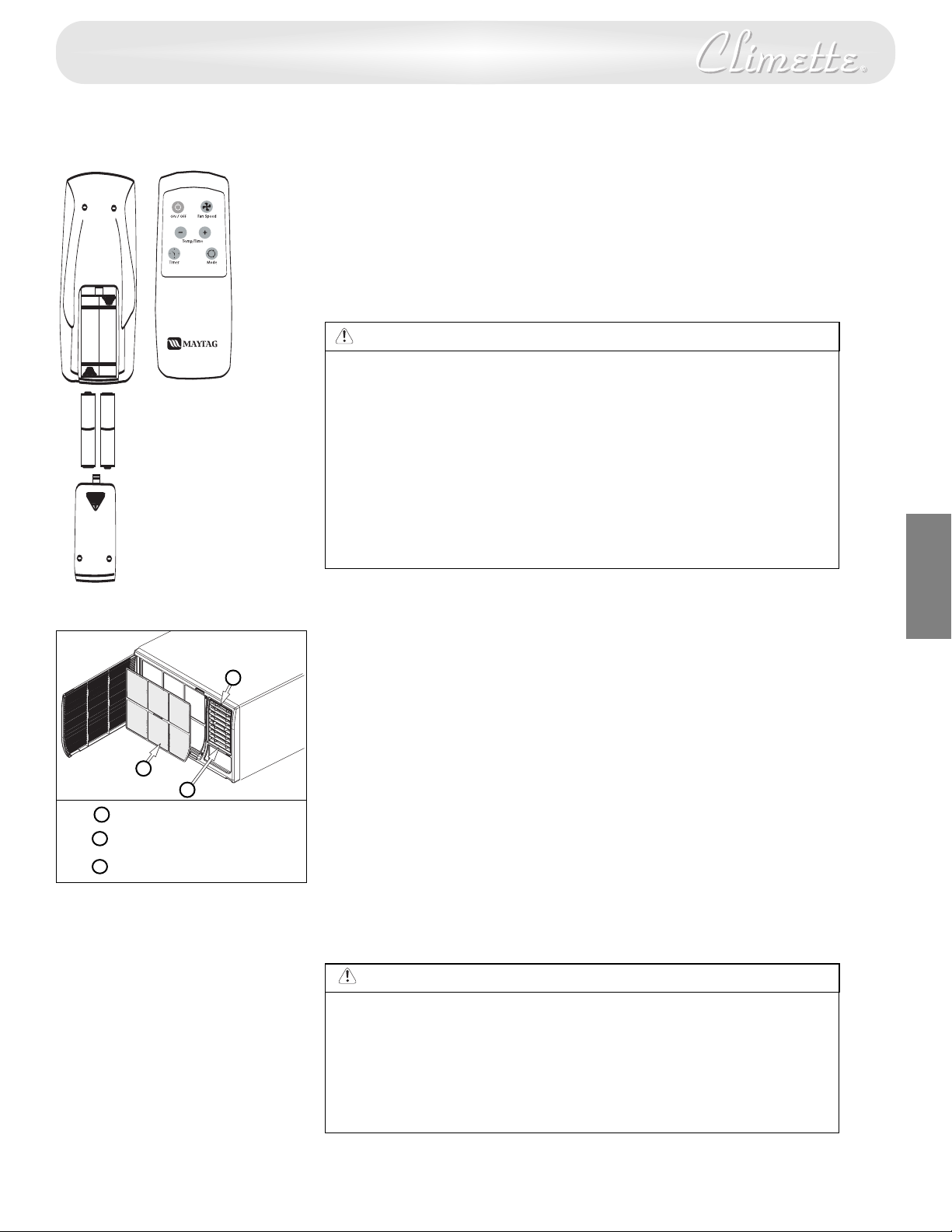
The functions work the same as your air conditioner’s
touch controls.
Batteries: Remove the cover on the back of the remote
controller and insert the batteries with the (+) and (-)
poles pointing in the proper direction.
WARNING
• Use only AAA or IEC R03 1.5V batteries.
• Remove the batteries if the remote controller is not used for a
month or longer.
• Do not mix alkaline, standard (carbon - zinc), or rechargeable
(nickle-cadmium) batteries.
• Do not attempt to recharge the supplied batteries
• All batteries should be replaced at the same time.
• Do not dispose of the batteries in a fire as they may explode.
• Do not mix old and new batteries.
• Do not install the batteries with the polarity (+/–) reversed.
• Keep batteries and other things that could be swallowed
away from young children. Contact a doctor immediately if
an object is swallowed.
Directing Airflow
Unit is engineered with adjustable louvers to direct
discharge airflow. Louvers are manually adjusted by
moving levers in direction of desired airflow.
C
Cleaning the Air Filter
Clean the filter every two weeks
1. Turn Master Control to OFF.
2. Remove the air filter by opening the air intake panel
on the decorative front and pull it out of the unit.
A
B
3. Wash in hot soapy water, rinse and shake dry.
4. Replace the filter, with the front of the filter toward
you.
5. To dry the filter thoroughly, run your unit for a few
minutes. Remember, only a clean filter works properly
and delivers top efficiency at every setting.
A
Filter
B
Louvers Vent door
C
CAUTION
Failure to keep air filter clean will result in poor air circulation.
DO NOT operate without filter. This can render the unit
inoperative.
Proper use and care of your air conditioner will help ensure
longer life of the unit. It is recommended to annually inspect
and clean the coils and condensate water passages. Expense of
annual inspection is the consumer’s responsibility.
7
7
Page 9
Troubleshooting Guide
Occurrence Possible Cause Solutions
ir conditioner will not operate
A
ir from unit does not
A
eel cold enough
f
Air conditioner cooling, • Outdoor temperature below 70°F. • To defrost the coil set thermostat to warmer
ut room is too warm —
b
ce forming on cooling coil
i
ehind decorative front
b
ir conditioner cooling,
A
om too warm —
but ro
O ice forming on cooling coil
N
ehind decorative front
b
To save time and expense, check the following before calling an authorized service station.
Wall plug disconnected. • Push plug firmly into wall outlet.
•
House fuse blown or circuit breaker tripped. • Replace fuse with time delay type
•
Unit turned off and then on too quickly. • If air conditioner is turned off,
•
• Thermostat set too low for cooling. • Adjust thermostat to higher setting for cooling.
Thermostat set too warm. • Set thermostat to colder temperature.
•
Room temperature below 70°F. • Cooling may not occur until room
•
Dirty air filter — air restricted. • Clean filter. See “Cleaning the Air Filter” section.
•
Dirty air filter — air restricted. • Clean air filter.
•
Thermostat set too warm. • Set thermostat to colder setting.
•
r reset circuit breaker.
o
ait 3 minutes before restarting.
w
emperature rises above 70°F.
t
osition.
p
Refer to “Cleaning Air Filter” section.
E
N
G
L
I
S
H
Noise when unit is cooling
Water dripping inside • Improper installation. • Tilt air conditioner slightly to the outside to
when unit is cooling allow water drainage. Refer to installation
Water dripping outside • Unit removing large quantity of moisture • This is normal during excessively humid days.
when unit is cooling from humid room.
• Air movement sound. • The sound of rushing air is normal. If too loud,
turn selector to lower fan setting.
• Sound of fan hitting water-moisture • This is normal when humidity is high.
removal system. Close doors, windows and registers.
• Window vibration — poor installation. • Refer to installation instructions —
check with installer.
instructions — check with installer.
8
8
Page 10

How to Obtain Warranty Service
Service for your Room Air Conditioner will be provided by
CareCo through its network of Authorized Independent
Servicers nationwide.
Note: Before calling for service, carefully read the "Installation
and Operating Instructions" booklet. Then if you need service:
1. Call a CareCo authorized service contractor and advise of
the model number, serial number, date of purchase and the
nature of your complaint. Service will be provided during
normal working hours. Contact your dealer for the name of an
authorized service contractor, if unknown to you.
2. If your dealer is unable to give you the name of a service
contractor or if you need other assistance, call CareCo at
1-800-332-6658
or write:
CareCo
415 Wabash Avenue
Effingham, IL 62401
Proof of Purchase Date
It is the responsibility of the consumer to establish the original
purchase date for warranty purposes. We recommend that a
bill of sale, canceled check or some other appropriate
payment record be kept for that purpose.
9
9
Page 11
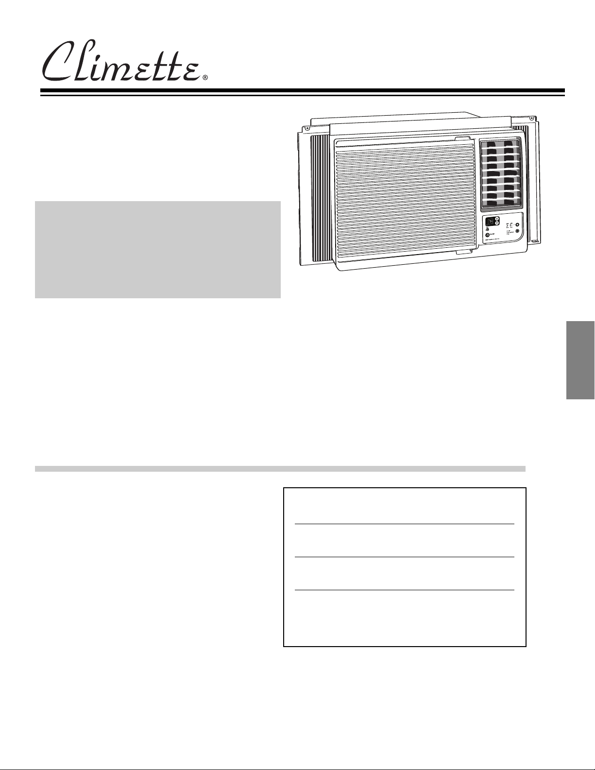
Manual de instalación y funcionamiento
Acondicionadores de aire
ambientales para
ventanas de guillotina y
empotrados en la pared
ESPAÑOL
Instrucciones importantes de seguridad....................1
Instalación....................................................................3
Funcionamiento ..........................................................6
Mantenimiento ..........................................................8
Localización y Solución de Averías ..........................9
Cómo obtener servicio o piezas bajo la garantía ..10
Guarde estas instrucciones para referencia futura
Para mayor información por favor llame al
1-217-347-6459
E
S
P
A
Ñ
O
L
Las características y especificaciones están sujetas a
cambio sin previo aviso.
Para referencia futura
Anote los númer
Encontrará los números de modelos y series en la mano
izquierda del panel decorativo. Use estos números en
cualquier correspondencia o llamadas de servicio respecto
a su aire acondicionado.
os de modelo y series
Modelo No.
Número de serie
Fecha de la compra
Page 12
Reconozca los símbolos,
advertencias y etiquetas de
seguridad
Información sobre las Instrucciones de
Seguridad
Las advertencias e instrucciones importantes sobre
seguridad que aparecen en este manual no están
destinadas a cubrir todas las posibles circunstancias y
situaciones que puedan ocurrir. Se debe ejercer
sentido común, precaución y cuidado cuando instale,
efectúe mantenimiento o cuando use este
distribuidor personal de bebidas.
Siempre póngase en contacto con su distribuidor,
agente de servicio o fabricante si surgen problemas o
situaciones que usted no comprenda.
Éste es el símbolo de alerta de seguridad. Sirve
para advertir al usuario de un posible riesgo para su
integridad física. Siga todos los mensajes de
seguridad que figuren después de este símbolo para
evitar lesiones o incluso la muerte.
PELIGRO
PELIGRO indica un riesgo el cual, si no se evita,
causará la muerte o una herida grave.
ADVERTENCIA
ADVERTENCIA indica un riesgo el cual, si no se
evita, puede causar la muerte o una herida grave.
PRECAUCIÓN
PRECAUCIÓN indica un riesgo, el cual, si no se evita,
puede causar heridas menores o moderadas.
PRECAUCIÓN
PRECAUCIÓN cuando se usa sin el símbolo de alerta,
indica una situación que podría resultar en el daño
del equipo.
ELIGRO
P
No guarde ni use gasolina u otros vapores y líquidos
inflamables en la vecindad de este o cualquier otro
artefacto. Los vapores emitidos pueden crear un riesgo
de incendio o explosión.
PELIGRO
Requerimientos Importantes para la Puesta a Tierra
• El cordón de alimentación del acondicionador de aire
tiene un enchufe de tres clavijas con puesta a tierra el cual
debe ser enchufado en un tomacorriente mural puesto a
tierra de tres alvéolos para su protección contra posible
riesgo de choque eléctrico. Para los modelos de hasta 7,5
amperes o menos, use un tomacorriente mural del tipo
con puesta a tierra que tenga la misma configuración que
el enchufe del cordón de alimentación.
• Para los modelos de más de 7,5 amperes, use un
tomacorriente mural sencillo con puesta a tierra que
tenga la misma configuración que el enchufe del cordón
de alimentación.
NNo
o
haga funcionar este acondicionador de aire sin
protección adecuada del circuito de retardo.
Consulte la placa de serie para los requerimientos
apropiados de alimentación eléctrica.
Tamaños Recomendados de los conductores del circuito
(Instalados según el código de construcción) :
CAPACIDAD DE CALIBRE DE LOS
LOS FUSIBLES CONDUCTORES
15 AMP #14 COMO MINIMO
20 AMP #12 COMO MINIMO
30 AMP #10 COMO MINIMO
125V
15A
250V
20A
250V
15A
250V
30A
PELIGRO
Riesgo de Choque Eléctrico
• Enchufe el aparato
eléctrico puesto a tierra.
• Con este aparato
adaptador de enchufe.
NNo
o
haga funcionar el acondicionador de aire sin el panel
•
delantero.
• Si el acondicionador de aire tiene una potencia nominal
indicada en la placa de serie de 115 voltios y de más de 7,5
amperes, es necesario que sea protegido con su propio
fusible o disyuntor y ningún otro dispositivo debe usar
ese mismo disyuntor o fusible.
• Si el acondicionador de aire tiene una potencia nominal
en la placa de serie de 230 voltios, es necesario que sea
protegido con su propio fusible o disyuntor y ningún otro
aparato debe usar ese mismo disyuntor o fusible.
• Recomendamos que un electricista calificado instale el
acondicionador de aire de acuerdo con el código eléctrico
nacional y los códigos y reglamentos locales.
• Use solamente conductores de cobre y fusibles de calibre
y capacidad adecuada.
ssoollaammeenntte
nnoo uusse
e
e
en un tomacorriente
un cordón de extensión ni un
1
Page 13
Cordón con dispositivo de detección de arco
eléctrico
El cordón eléctrico proporcionado con este acondicionador
de aire viene equipado con un dispositivo de detección de
arco eléctrico diseñado para apagar el suministro eléctrico a
la unidad cuando detecta una condición de falla por arco
eléctrico. Una falla por arco eléctrico es una descarga
eléctrica accidental cuando los artefactos o cables eléctricos
stán dañados, son antiguos o no se han usado de manera
e
adecuada. Una falla por arco eléctrico puede ser peligrosa si
no se detecta a tiempo.
PELIGRO
o
•• NNo
retire o modifique este enchufe
o
•• NNo
lo utilice como un interruptor de
encendido/apagado
o
•• NNo
lo use en el exterior
o
•• NNo
coloque muebles contra o sobre el cordón
eléctrico. Esto puede disparar el interruptor de
prueba y/o dañar el cordón, además de crear una
condición potencial de arco eléctrico
o
•• NNo
intente reparar el cordón. Si necesita reemplazar el
cordón, llame a un técnico de servicio autorizado
• El dispositivo de detección de arco eléctrico no es un
interruptor de falla de conexión a tierra y no se debe
usar como tal
• El dispositivo de detección de arco eléctrico contiene
un tablero de circuitos electrónico y no se debe
sumergir o exponer al agua
Restablecimiento
Si el dispositivo de detección de arco eléctrico se ha
disparado, el botón ‘RESET’ (Restablecer) se levantará.
Siga los siguientes pasos para restablecer el dispositivo de
detección de arco eléctrico:
1. Desenchufe la unidad del tomacorriente
2. Oprima el botón ‘RESET’ (Restablecer)
3. Enchufe la unidad nuevamente en el tomacorriente
4. V
erifique que llega energía eléctrica a la unidad
Pruebas
Realice pruebas del dispositivo de detección de arco eléctrico
una vez al mes, después de cada tormenta eléctrica grande, o
si se ha interrumpido el suministro eléctrico al acondicionador
de aire de habitación.
Siga los siguientes pasos para probar el dispositivo de
detección de arco eléctrico:
1. Desenchufe la unidad del tomacorriente
2. Oprima el botón ‘RESET’ (Restablecer)
3. Enchufe la unidad nuevamente en el tomacorriente
4. Oprima el botón de prueba. El dispositivo debe dispararse
y el botón ‘RESET’ (restablecer) debe levantarse.
5. Oprima el botón ‘RESET’ (Restablecer) nuevamente para
activar la unidad
Si la prueba anterior falla, deje de usar el acondicionador de
aire y póngase en contacto con servicio al cliente.
DVERTENCIA
A
Emplee a dos o mas personas para mover e instalar el
acondicionador de aire.
PRECAUCIÓN
• No corte, modifique ni retire ningún pedazo de
poliestireno expandido (espuma blanca) situado dentro
de este acondicionador de aire.
• No introduzca objetos en el área de descarga del aire.
Esto puede causar daño irreparable a su acondicionador
de aire.
• No vierta líquidos de limpieza en el acondicionador de
aire pues esto puede causar un malfuncionamiento. Use
un paño húmedo para limpiarlo.
PRECAUCIÓN
• Evite usar solventes fuertes para limpiar el
acondicionador de aire.
• Limpie el filtro del acondicionador de aire cada dos
semanas para evitar sobrecalentamiento causado por
obstrucción del aire.
• No obstruya el área de entrada del aire de su
acondicionador, pues esto puede causar
sobrecalentamiento, lo cual activará el interruptor de
seguridad y apagará el aparato.
• No bloquee la circulación del aire hacia las rejillas de
ventilación exteriores del gabinete.
• No obstruya el flujo del aire hacia el interior con
persianas, cortinas o muebles o hacia el exterior con
arbustos, recintos u otros edificios.
No haga funcionar el acondicionador de aire teniendo
•
instalada la cubierta protectora exterior
resultar en daño mecánico dentro del acondicionador de
aire.
• Soporte adecuado de la pared para el peso del
acondicionador de aire durante un período de tiempo
prolongado.
. Esto podría
E
S
P
A
Ñ
O
L
2
2
Page 14
imensiones de la Ventana
D
ste acondicionador de aire ha sido preparado en la fábrica para su
E
instalación en ventanas de guillotina estándares con aberturas de
26,875” a 41,625” de ancho y una abertura vertical de por lo menos
15,625” mínimo desde la parte inferior de la hoja móvil hasta el
umbral. El acondicionador de aire puede ser instalado en ventanas
de 24” de ancho, si se retiran los paneles de sellado laterales del
gabinete.
23 7/8” a 41 5/8”
A
A
B
15 5/8” mínimo
B
Herramientas Necesarias
Destornilladores
Nivel
Llave de tuercas de trinquete
inta de medir
C
Identificación de Tornillo
Partida
A
Tornillo de madera de 5/8”
B
Instalacion en la ventana
Desmontaje del Panel Decorativo Delantero
1. Retire los tornillos que se encuentran a ambos lados del
gabinete.
2. Tire suavemente hacia adelante mientras sostiene
los dos lados del frente decorativo.
Desmontaje del Chasis
1. Retire los dos (2) tornillos de embarque* del costado inferior
trasero del gabinete.
2.
Retire los dos (2) tornillos antirrobo de ambos lados delanteros
inferiores del gabinete. CONSERVE ESTOS TORNILLOS, ellos
serán usados posteriormente en la instalación.
3. Deslice el chasis fuera del gabinete sujetando la manija de la
bandeja inferior y tirando hacia adelante a la vez que sujeta el
barra superior.
Instalación del Marco del Panel de Relleno
1. Deslice el marco del panel de relleno en el gabinete del
acondicionador de aire usando las guías que se encuentran
arriba y abajo de la unidad. Deslice el marco lo más cerca
posible del acondicionador de aire para que la cortina quede
trabada en la posición adecuada.
2. Tire suavemente del marco hasta obtener la longitud que
necesita para realizar la instalación.
ombre la parte
N
Tornillo de madera de 1”
C
Gabinete
A
Panel Decorativo
B
A
B
C
Tornillos de embarque
A
Gabinete
B
Tornillos antirrobo*
C
B
Cantidad
1
4
A
D
C
A B
B
Delantero Tornillo
C
E
Chasis
D
E
Manija de la
bandeja inferior
A
C
PRECAUCIÓN
Tenga cuidado cuando esté trabajando alrededor de las
esqinas afiladas del gabinete ara evitar heridas o ropas
rasgadas.
3
3
Barra superior
A
B
Marco del Panel de relleno
C
Borde de fijación
D
E
Barra inferior
D
Gabinete
E
Page 15
A
Umbral de la ventana
Barra inferior
B
Instalacion en la Ventana
1. Abra la ventana y marque el centro del umbral de la
ventana. Coloque cuidadosamente el gabinete en la
ventana y alinee el agujero central de la barra inferior
con la marca central trazada en el umbral de la
B
A
C
Tornillo de 1”
C
ventana.
2. Cierre la hoja móvil inferior de la ventana hasta que
toque el aparato detrás de la barra de retén superior.
(No suelte el gabinete hasta que la hoja móvil inferior
esté en su posición final).
A
B
D
3. Instale el gabinete en el umbral de la ventana
colocando un tornillo de 1” de largo a través de la
barra de unión inferior hacia el umbral de la ventana.
Asegureidad de los paneles de relleno
C
4. Deslice los paneles de relleno hacia afuera hasta que
toquen los rieles de la hoja móvil de la ventana.
5. Asegure la parte superior de los paneles de relleno
instalando tornillos de 5/8” de largo a través de los
D
agujeros de montaje superiores hacia el umbral de la
ventana.
A
Nivel
Hoja móvil de la ventana
B
C
Panel de relleno
A
B
C
D
F
G
E
A
Espuma de
relleno
B
Hoja móvil
inferior
C
Panel de
D
E
F
relleno
Tornillo de madera de 5/8”
D
E
Umbral de la ventana
H
Moldura
Umbral de
la ventana
Tornillo
antirrobo
Chasis
G
Panel
H
decorativo
delantero
E
6. Asegure la parte inferior de los paneles instalando
tornillos de 5/8” de largo en el umbral de la ventana a
través de las lengüetas del panel de relleno.
7. Instale el chasis en el gabinete (página 15).
E
S
P
A
Ñ
O
ADVERTENCIA
No obstruya el área de la entrada del aire de su
acondicionador, pues esto puede causar
sobrecalentamiento, lo cual activará el interruptor de
seguridad y apagará el aparato. No bloquee el flujo del aire
hacia el interior con persianas, cortinas o muebles o hacia el
exterior con arbustos, recintos u otros edificios
L
Instalación del Chasis en el Gabinete
1. Deslice el chasis hacia el interior del gabinete.
Para reinstalar el panel decorativo delantero, colóquelo
2.
en su lugar y empújelo hacia atrás hacia el
acondicionador hasta que entre a presión en su lugar.
uelva a instalar el tornillo de retén detrás del panel de
V
entrada del aire.
3. Reinstale los dos tornillos antirrobo en los lados
delanteros inferiores del gabinete.
4. Corte un relleno de espuma de plástico del ancho de la
ventana e instálelo entre la hoja móvil superior e
inferior de la ventana.
Use compuesto obturador para llenar cualquier
5.
abertura más pequeña.
ADVERTENCIA
N
o taladre un agujero en la bandeja inferior. El
acondicionador de aire ha sido diseñado para
funcionar aproximadamente con 1/2” de agua en la
bandeja inferior
.
4
4
Page 16
B
A
arra superior Tornillo de madera de 5/8”
B
A
Marco de madera
A
Tornillos de madera de 1”
B
Gabinete
C
Barra inferior
D
Pared
E
Panel decorativo
F
delantero
Soporte de madera de
G
por lo menos 1 x 6
(clavado o atornillado en
co de madera)
el mar
B
O
D
P
G
H
K
L
O
M
P
D
N
co de madera de
Mar
H
2" por todo el rededor
Espacio de 1-1/2”
I
Espacio de 1-1/4”
J
Enchapado de ladrillo
K
L
Dintel angular
Material obturador
M
Guardaaguas
N
ierteaguas)
(V
Rejillas de ventilacion
O
relleno de madera
P
nstalación del Gabinete en una Ventana
I
de Ancho Mínimo
.No instale los paneles de relleno en el gabinete.
1
2. Consulte las instrucciones anteriores desde el paso 1 al 3.
3. Cierre la ventana hasta que toque detrás de la barra superior del
acondicionador de aire.
4. Asegure la hoja móvil inferior de la ventana en el marco de la ventana.
. Si se requiere relleno en ambos lados del acondicionador de aire, corte
5
na espuma de plástico del tamaño adecuado y tape ambos lados.
u
6. Use compuesto obturador para llenar cualquier abertura más pequeña.
A
B
C
J
E
F
M
I
J
M
I
7. Instale el chasis en el gabinete.
Consulte a su distribuidor autorizado o al importador para obtener
instrucciones de instalación alternativas.
Instalación Empotrado en la Pared
Este acondicionador de aire ha sido diseñado como un chasis deslizable, haciendo
que sea posible su instalación empotrado en la pared, tanto en muros de
construcción antigua como moderna. Recomendamos que este tipo de
instalación sea realizado con ayuda profesional.
• IMPORTANTE: Este aparato debe ser instalado de acuerdo con todos los códigos
y reglamentos eléctricos y de construcción aplicables.
• Se recomienda que usted solicite ayuda para instalar el aparato y que use una
técnica de alzamiento adecuado para evitar lesión personal.
• Es importante que usted inspeccione el estado de la pared donde se instalará
el acondicionador de aire.
• Asegúrese de que la pared pueda soportar el peso del acondicionador de aire.
• Todas las rejillas de ventilación del gabinete DEBEN QUEDAR hacia el lado
exterior de la pared. NO BLOQUEE LAS REJILLAS DE VENTILACION LATERALES.
• El gabinete debe ser instalado de modo que quede nivelado de lado a lado y
con una ligera inclinación hacia abajo desde el interior al exterior.
1. Retire primero el panel decorativo delantero y el chasis del gabinete.
Retire la barra superior del gabinete.
2. Determine el tamaño de la abertura para construir un marco de madera
agregando 1/8” al ancho y a la altura del gabinete. Mida la altura desde
la parte superior del gabinete hasta la barra inferior. Agregue esta
medidas al grosor de la madera usada para construir el marco. Esto
determinará el tamaño necesario de la cavidad en la pared. El marco debe
construirse usando madera de por lo menos 1” de espesor
determine el grosor del marco acabado, asegúrese de que este no cubra las
rejillas de ventilación laterales del gabinete.
3. Instale el marco terminado en la cavidad mural de manera que quede a
escuadra y nivelado, luego clávelo o atorníllelo firmemente en la pared e
introduzca el gabinete en la cavidad mural ya preparada con el marco.
4. Asegúrese de que el gabinete sobresalga de la pared 1-1/4” en la parte
superior y 1-1/4” en la parte inferior hacia la habitación para asegurar una
inclinación adecuada y acceso al tornillo antirrobo, luego asegure el
gabinete en el marco instalando doce (12) tornillos de madera de 1” (no
suministrados) a través de los agujeros taladrados en el gabinete y hacia el
marco.
Si el acondicionador se instala en un muro enchapado de ladrillo se debe usar
un dintel angular de acero para sostener los ladrillos que están arriba del
gabinete.
5. Una vez que se haya instalado el gabinete obture todas las aberturas en el
interior y exterior entre el marco acabado y el gabinete para evitar que la
humedad penetre al interior de la pared. El uso de un guardaaguas
(vierteaguas) ayudará también a evitar que el agua gotee dentro de la
pared.
6. Instale el chasis en el gabinete.
5
5
. Cuando se
Page 17
Panel de Control Electrónico
Built in Three Minute Cooling Delay
C
ool
H
igh
Timer
Med
A
uto
Low
Fan
Energy Save
Heat
On/Off
Control de Alimentación
Este botón pone en marcha y apaga el acondicionador de aire.
Indicador de Temperatura de Ajuste/Temporizador
El indicador muestra la temperatura de ajuste cuando el acondicionador de
ire está en funcionamiento y las horas cuando se ha activado el temporizador.
a
EL INDICADOR DE LA TEMPERATURA SOLAMENTE MUESTRA LA
TEMPERATURA DE AJUSTE, NO LA TEMPERATURA AMBIENTE REAL.
Control de la Temperatura/ Temporizador
Estos botones se usan para aumentar o reducir la temperatura de ajuste en
incrementos de 1°, entre 66°F hasta 88°F. Si se oprimen simultáneamente
ambos botones, el indicador digital cambiará entre grados Celsius y Fahrenheit.
Cuando se activa el temporizador, estos botones son usados para cambiar el
ajuste de la hora en incrementos de 1, entre 00 hasta 24.
Selector de Modo
Una luz verde indicará el modo que está siendo utilizado.
Modo ‘Cool’ (Frío) –
El acondicionador de aire circula y enfría el aire.
Modo ‘Heat’ (Calor) [Solamente los Modelos con Calor] –
El acondicionador de aire circula y calienta el aire.
Característica de Seguridad del Calentador – Cuando el calentador está
apagado, el ventilador de baja velocidad se activará y funcionará durante
60 segundos para asegurar la eliminación de algún calor residual, a la vez que
el diodo LED ‘Low Fan’ (ventilador de baja velocidad) destella hasta que se
detenga el ventilador de baja velocidad.
Modo ‘Fan’ (Ventilador) –
El acondicionador de aire solamente hará circular el aire.
Modo ‘Energy Saver’
(Ahorro de Energía) –
(El modo de ahorro de energía está diseñado para funcionar solamente con el
modo ‘Cool’). El ventilador cambiará de la velocidad de ajuste a velocidad baja
cuando el compresor sea apagado por el termostato. Cuando el compresor se
activa nuevamente, el ventilador volverá al ajuste original. La velocidad
del ventilador cambia automáticamente según cambie la temperatura en la
habitación.
Control de la Velocidad del Ventilador – Alta, Mediana,
Baja y Automática
El ajuste de la velocidad del ventilador se cambia cada vez que se oprime
el botón de control de velocidad del ventilador. Una luz verde indicará el
ajuste que se ha seleccionado.
Cuando se selecciona ‘Auto’ (Automático) y el acondicionador de aire está
en el modo ‘Cool’ o ‘Heat’, la velocidad del ventilador cambiará
automáticamente a medida que cambie la temperatura en la habitación.
En el modo ‘Cool’, cuando la habitación llega a 7° o más, sobre la
temperatura de ajuste, se usa ‘High Fan’ (Alta Velocidad), cuando la
temperatura en la habitación es de 4° o menos, sobre la temperatura de
ajuste, se usa ‘Low Fan’ (Velocidad Baja). En el modo ‘Heat’ cuando la
habitación alcanza 7° o más, bajo la temperatura de ajuste, se usa 'High
Fan', cuando la habitación alcance 4° o menos, bajo la temperatura de
ajuste, se usa 'Low Fan'. En todos los otros casos el ventilador usa 'Medium
Fan' (velocidad mediana).
Control Electrónico
(Enfriamiento Solamente)
A
B
C
F
D
E
Control Electrónico (Calor/Frío)
A
B
C
F
D
E
A
Indicador de Temperatura/Temporizador
Ajuste de la Temperatura y del
B
Temporizador
C
Encendido/Apagado del Temporizador
D
Control de la Velocidad del Ventilador
Selector de Modo
E
Control de Alimentación
F
E
S
P
A
Ñ
O
L
ADVERTENCIA
Mecanismo de retraso de tres minutos
incorporado
Si este aparato electrónico no responde a los
mandos del control remoto o cojinete táctil, será
necesario desenchufarlo cinco segundos y luego
volver a enchufar
.
Característica de encendido automático:
In caso de falla eléctrica, esta característica
permite que la unidad se encienda
nuevamente de manera automática cuando
se restablece el servicio eléctrico
manteniendo ls ajustes más recientes.
ADVERTENCIA
Los modelos con Frío/Calor o con calor
eléctrico han sido diseñados para ser
usados como una fuente de calor
suplementaria. Son sólo un complemento
para los sistemas de calefacción habituales
y nunca deben usarse como la fuente
primaria de calefacción.
6
6
Page 18
C
Built in Three Minute Cooling Delay
Cool
High
Timer
Med
Auto
Low
F
an
Energy Save
Heat
O
n/Off
ontrol del Temporizador
(El temporizador puede ser
ajustado ya sea para encender o apagar el acondicionador de aire.)
Para PONER EN MARCHA automáticamente el
acondicionador de aire usando el modo ‘Timer’:
1. Oprima el botón ‘Timer’ cuando la alimentación
eléctrica esté desconectada. El indicador mostrará 00.
Ajuste el indicador para que muestre el número de horas
que desea que transcurran antes de la PUESTA EN
MARCHA, usando las flechas de ajuste ‘Temperature/Timer’
(Temperatura/Temporizador).
2. El indicador mostrará la cantidad de horas que faltan
para la PUESTA EN MARCHA.
3. Para salir del modo ‘Timer’, oprima el botón ‘Timer’.
Una luz verde situada junto al botón ‘Timer’ se
4.
iluminará para indicar que el ‘Timer’ está activado.
Para APAGAR automáticamente el acondicionador de aire
usando el modo ‘Timer’:
1. Oprima el botón ‘Timer’ cuando la alimentación
eléctrica esté conectada. El indicador mostrará 00. Ajuste
el indicador para que muestre el número de horas que
desea que transcurran antes de que se APAGUE usando las
flechas de ajuste ‘Temperature/Timer’
(T
emperatura/Temporizador). (Después de 10 segundos, el
indicador volverá automáticamente a la temperatura de
ajuste.)
2. Para ver la cantidad de horas que faltan para que se
APAGUE el acondicionador de aire, oprima una vez el
botón ‘Timer’.
3. Para salir del modo ‘Timer’, oprima el botón ‘Timer’
dos veces.
4. Una luz verde situada junto al botón ‘Timer’ se
iluminará para indicar que el ‘Timer’ está activado.
Control Electrónico
Enfriamiento Solamente)
(
A
B
C
F
Control Electrónico (Calor/Frío)
A
B
C
F
A
Indicador de Temperatura/Temporizador
Ajuste de la Temperatura y del
B
Temporizador
C
Encendido/Apagado del Temporizador
D
Control de la Velocidad del Ventilador
Selector de Modo
E
Control de Alimentación
F
D
E
D
E
7
7
Page 19
Control Remoto de Acondicionador de Aire
AAA
IEC R031.5V
+
-
AAA
IEC R03
1.5V
as funciones trabajan igual que los controles manuales de su acondicionador
L
de aire.
Pilas:
Retire al tapa en la parte trasera del control remoto e inserte las baterías con
os polos (+) y (-) en la dirección correcta.
l
PRECAUCION
• Use solabente pilas AAA o IEC R03 de 1,5V.
• Retire las pilas si el control remoto no va a ser usado durante un mes o
más.
• No intente recargar las pilas suministradas.
• Todas las pilas deben ser reemplazadas a un mismo tiempo.
• No incrinere las pilas pues pueden explotar.
• No instale las pilas con la polaridad (+/-) inversa.
• Mantenga fuera del alcance de los niños pequeños las pilas y otros
artículos que puedan ser tragados.
Póngase inmediatamente en contacto con un médico si un niño
pequeño se traga un objeto.
• No mezcle pilas alcalinas, standard (carbon-zinc), con pilas recargables (nickel-
cadium).
E
S
P
A
Ñ
O
Dirección del Flujo del Aire
El acondicionador de aire ha sido diseñado con rejillas de ventilación
C
ajustables para orientar el flujo de aire descargado. Las rejillas de
ventilación se ajustan manualmente moviéndolas en la dirección deseada del
flujo del aire.
L
Limpieza del Filtro del Aire
Limpie el filtro cada dos semanas
A
B
A
Filtro
La puerta de ventilación
B
C
Rejillas de Ventilación
1. Gire el control maestro a ‘OFF' (Apagado).
Retire el filtro del aire abriendo el panel de entrada del aire situado en el
2.
panel decorativo delantero y sacándolo fuera del acondicionador de aire.
Lávelo en agua con jabón, enjuague y sacúdalo para secarlo.
3.
4. Vuelva a colocar el filtro con la parte delantera del filtro dirigida hacia
usted.
5. Para secar bien el filtro, haga funcionar el acondicionador de aire
durante unos pocos minutos. Recuerde: solamente un filtro limpio puede
proporcionar eficiencia y funcionar de manera correcta en todos los
ajustes.
PRECAUCION
Si no se mantiene el filtro del aire limpio puede causar circulación deficiente del
aire. NO haga funcionar el acondicionador de aire sin el filtro. Esto puede impedir
que el acondicionador de aire funcione.
El uso y cuidado adecuado de su acondicionador de aire le asegurará una vida útil
prolongada. Se recomienda que inspeccione anualmente y limpie las espirales y los
pasajes del agua del condensado. El costo de la inspección anual es responsabilidad
del propietario.
8
8
Page 20
Localización y Solución de Averías
ara ahorrar tiempo y dinero, verifique lo siguiente antes de llamar a un centro de servicio autorizado.
P
Problema
El acondicionador de aire no
funciona
El aire proveniente del
acondicionador de aire no es
suficientemente frío
El acondicionador de aire enfría,
pero la habitación está demasiado
tibia – se forma hielo en las
espirales de enfriamiento detrás
del panel decorativo delantero
El acondicionador de aire enfría,
pero la habitación está demasiado
tibia – NO se forma hielo en las
espirales de enfriamiento detrás
del panel decorativo delantero
Se produce ruido cuando el
acondicionador de aire está
enfriando
Causa Posible
• El enchufe mural está desconectado.
• Se ha fundido un fusible o se ha
isparado el disyuntor.
d
El acondicionador de aire se apagó y
•
luego se encendió demasiado
rápidamente.
• El ajuste del termostato es muy bajo para
enfriamiento.
• El termostato está en un ajuste
demasiado caliente.
• La temperatura de la habitación es
inferior a 70°F.
• La temperatura exterior es inferior a 70°F.
• El filtro de aire está sucio – restricción del
aire.
• El termostato está en un ajuste
demasiado frío para enfriamiento
nocturno.
• Filtro de aire sucio – restricción del aire.
• Ruido del movimiento del aire.
• Ruido del ventilador al golpear el sistema
de extracción de agua y humedad.
• Vibración de la ventana – instalación
deficiente.
Soluciones
• Inserte bien el enchufe en el tomacorriente
mural.
• Reemplace el fusible con un tipo de fusible con
etardo o reponga el disyuntor.
r
Si el acondicionador de aire está apagado
•
espere 3 minutos antes de volver a encenderlo.
• Cambie el termostato a un ajuste más alto para
enfriamiento.
• Coloque el termostato en una temperatura más
fría.
• No se producirá enfriamiento hasta que la
temperatura de la habitación no sea superior a
70°F.
Para descongelar el serpentín, coloque el
•
termostato en una posición más caliente.
• Limpie el filtro, vea la sección “Limpieza del
Filtro del Aire”.
• Para descongelar la espiral, coloque el
termostato en una posición normal.
• Limpie el filtro del aire. Consulte la sección
“Limpieza del Filtro del Aire”.
• El sonido del aire moviéndose es normal. Si es
demasiado fuerte, gire el selector a un ajuste
del ventilador más bajo.
• Esto es normal cuando la humedad es alta.
Cierre las puertas, ventanas y rejillas de
ventilación.
• Consulte las instrucciones de instalación –
consulte con el instalador.
Goteo de agua dentro del
acondicionador de aire cuando
está enfriando
Goteo de agua fuera del
acondicionador de aire cuando
está enfriando
• Instalación incorrecta.
El acondicionador de aire esta extrayendo
•
gran cantidad de humedad de
habitación.
9
9
• Incline ligeramente el acondicionador de aire
hacia el exterior para desaguar el agua.
Consulte las instrucciones de instalación –
verifique con el instalador.
Esto es normal durante días excesivamente
•
húmedos.
 Loading...