

Page 1
Parts Manual
Floor type Gas Convection Steamer
Series: SteamCraft Model 24CGA10.2
1333 East 179
Cleveland, Ohio 44110
Phone: (216) 481-4900
1-800-338-2204
Fax: (216) 481-3782
www.clevelandrange.com
th
Street
Page 2
Page 3
Page 4

High limit clamp:
109464
Page 5
108207 Nozzle
Page 6
Page 7
Page 8
300145
Page 9
Page 10

Condensate
Solenoid
Manifold
110527
Page 11

Page 12

Page 13

Page 14

Burner box gasket 107947
Fan Gasket 110520
Boiler to Burner Box Gasket
108898
Page 15

Statement of Responsibilities
This document is for use by experienced and trained Qualified Cleveland Range, LLC Authorized Service
Representatives who are familiar with both the safety procedures, and equipment they service.
Cleveland Range, LLC assumes no liability for any death, injury, equipment damage, or property damage
resulting from use of, improper use of, or failure to use the information contained in this document.
Cleveland Range, LLC has made every effort to provide accurate information in this document, but
cannot guarantee that this document does not contain unintentional errors and omissions.
The information in this document may be subject to technical and technological changes, revisions, or
updates.
Cleveland Range, LLC assumes no liability or responsibility regarding errata, changes, revisions, or
updates.
Qualified Cleveland Range, LLC Authorized Service Representatives are obligated to follow industry
standard safety procedures, including, but not limited to, OSHA regulations, and disconnect / lock out /
tag out procedures for all utilities including steam, and disconnect / lock out / tag out procedures for gas,
electric, and steam powered equipment and / or appliances
All utilities (gas, electric, water and steam) should be turned OFF to the equipment and locked out of
operation according to OSHA approved practices during any servicing of Cleveland Ran ge equipment
Qualified Cleveland Range, LLC Authorized Service Representatives are obligated to maintain up-to-date
knowledge, skills, materials and equipment.
Page 16

Cleveland Range Inc.
1333 East 179th St., Cleveland, Ohio, U.S.A. 44110
Ph: 1-216-481-4900 Fx: 1-216-481-3782
Visit our Web Site at www.clevelandrange.com
MODEL: 24-CGA-10.2
ITEM NUMBER __________________________________________
JOB NAME / NUMBER __________________________________
Cleveland Standard Features
■ Cooking Capacity for up to ten 12˝ x 20˝ x 2 1/2˝ deep
Cafeteria Pans, five each compartment.
■ Totally independent cooking compartments, each has its'
own generator, gas valve and water level controls - no
shared components
■ Exclusive High Efficiency Gas Power Burner (forced air)
Generator: Produces more steam for faster cooking while
lowering operating costs (72M BTU's per compartment)
■ Easy Access Cleaning Port: Each generator has a deliming
port located on the outside, top of the unit
■ Generator Cleaning Light for each compartment warns the
operator to delime generator
■ Instant Steam Standby Mode:Holds generator at a
steaming temperature, allows unit to start cooking instantly
■ Each compartment has one, 60-Minute Electro-Mechanical
Timer with load compensating feature.Manual Bypass
Switch for constant steaming.
■ Durable 14 Gauge, 304 Stainless Steel construction for
compartment door, cooking cavity and steam generator
■ Exclusive Two-Piece Compartment door: Slammable,
self-adjusting door provides and airtight seal, reversable
door gasket for extended life
■ Exclusive Gemini Drain/Power Control System: Simple,
reliable 1/2" ball valve style drain automatically turns power
ON/OFF
■ Exclusive Brass Steam Jets distribute even-high velocity
steam throughout cooking compartment for faster cooking
times
■ Easy, Front -Access Generator Controls comes with a
pullout drawer for simple servicing of unit
■ 6˝ Stainless Steel Adjustable Legs with Flanged Feet
■ Approvals:CSA (AGA, CSA) and U.L/NSF#4
■ Compartment Steam Shut-Off Switch (SCS)
Options & Accessories
❐ Electronic Timer with Compensating Feature (ETC)
❐ On/Off Steam Switch Controls, no timer (MC)
Shall be Two Compartments, Cleveland Convection Steamer series
SteamCraftGeminiTM10
, Model 24-CGA-10.2, Twin Gas Atmospheric
Steam Generator, 72M BTU"s input per compartment.
Independent
steam generator, gas valve and water level control system.
Automatic Generator Blowdown. Steam Generator with Automatic Water
Fill on start up.
Exclusive remote probe-type water level controls.
Exclusive Brass “Steam Jet” distribution system. Two-piece freefloating compartment door.
Type 430 Stainless Steel exterior and cook-
ing compartments.
Pullout service drawer for controls and Gemini
Drain/Power Control System.
Exclusive Cold Water Condenser design.
Choice of Compartment Controls. Manual
❐ Propane Gas (PG)
❐ Dissolve
®
Descale Solution, 6 one gallon container w/quart
markings (106174)
❐ Water Filters
Short Form Specifications
SECT. IV PAGE 13
0402
SteamCraft®GeminiTM10
TWO COMPARTMENT FLOOR MODEL DESIGN
PRESSURELESS CONVECTION STEAMER
TWIN, INDEPENDENT GAS-FIRED GENERATORS
Page 17

(NOT TO SCALE)
SECT. IV PAGE 14
0402
Litho in U.S.A.
GAS ELECTRIC COLD WA TER CLEARANCE DRAINAGE
11⁄4˝ IPS line size, 3⁄4˝ (13mm) connection 120V-1Phase, 60 Hz. 35 psi minimum RIGHT = 3˝ operating, 11⁄2˝ dia.
NATURAL PROPANE BTU 2 Blowers & Controls 60 psi maximum 12˝ if adjoining wall or Do not connect other
Piping
3
⁄
4
˝ N.P.T. Piping
3
⁄
4
˝ N.P.T. 72,000 each 150 watts each LEFT = 3˝ units to this drain
Supply pressure Supply pressure Generator, One (E) 1/4" dia. REAR = 3˝
4.50˝ W.C .Min. 11.00˝ W .C .Min. 144,000 total NPT for Generator Allow 6˝ space min. Drain must be vented
14.00˝ W.C .Max. 14.00˝ W.C .Max. from rear and sides
One (D) 1/4" dia when located near Do not use PVC pipe
Manufacturer must be notified if unit will NPT for Condenser combustible walls
be used above 2,000 feet
C
D
NOTES:
Cleveland Range reserves right of design improvement or modification, as warranted.
Many regional, state and local codes exist and it is the responsibility of the owner and installer to comply with the codes.
Cleveland Range equipment is built to comply with applicable standards for manufacturers. Included among those approval agencies are UL/NSF#4 and CSA (AGA, CGA).
Each Compartment has
capacity for:
• Five, 12˝ x 20˝ x 2
1
⁄2˝ deep
Cafeteria Pans.
WATER QUALITY
REQUIREMENTS
The quality of water varies
greatly from region to region.
Steam equipment generators
must be drained daily and
chemically descaled periodically
to ensure proper operation. To
minimize service problems
caused by the accumulation of
minerals and chemicals in water
review the following quality
guidelines with a local water
treatment specialist. Inlet water
that is beyond these specified
guidelines should be treated to
achieve these acceptable limits.
Total Dissolved Solids less than
60 ppm, Alkalinity less than 20
ppm, Silica less than 13 ppm,
pH factor greater than 7.5,
Chlorine less than 30 ppm.
Right - 3”, Left - 3”,
Rear -3”
(12” on control side if adjoining
wall or equipment is over 30”
high for service access)
Contact factory
for variances to
clearances.
A B C
DE
Page 18

CLEVELAND RANGE GEMINI 24CGA 6.2
AND 24CGA10.2
SEQUENCE OF OPERATIONS
Mechanical Timer
Starting with the timed manual switch in the timed position, and no time on the timer.
1. To turn the unit on, turn the ON/OFF lever clockwise to the ON position
• This mechanically closes the drain.
• The red “Power On” indicator is energized.
• 115 VAC is sent through the timer to the three-second timer, which activates the
buzzer for three seconds.
• 115 VAC is sent through the normally closed R1 contacts to the fan motor, turning it
ON
•
115 VAC is sent to H and N of the water level board
2. With the water level board energized and no water in the generator
• 115 VAC is sent from the FILL terminal to the fill solenoid.
• The fill solenoid opens and the generator fills.
3. The water fills to the low probe shorting it to ground
•
115 VAC is sent from the HEAT terminal to the timed manual switch.
•
115 VAC is sent through the high limit to the primary of the 24VAC transformer.
•
The water continues to fill until the water level reaches the high probe then 115 VAC is
removed from the FILL terminal and the fill solenoid is turned off
4.
24VAC is sent to the ignition module.
•
Spark is sent to the igniter.
•
24VAC is sent to the pilot coil of the gas valve and the coil of the R1 relay.
•
The normally closed R1 contacts open, turning off the fan
•
The pilot lights, which acts as a standby heater. When the pilot is ignited and the
module detects 1.0 micro amps DC, the MV terminal on the module is energized it
remains in this standby heat mode until a cooking compartment is turned “ON” (see
step 5).
5. When the timed/manual switch is in the timed position and time is on the timer or the timed
manual switch is set to the manual position:
• 115 VAC is sent to the clean light timer.
• When the clean light timer times down 115 VAC is sent to the clean light switch.
• When the clean light switch is depressed the timer is reset.
• 115 VAC is sent from the compartment timer through the door switch to the normally
closed contacts of the compartment thermostat and R2 relay coil.
• The “Sure Cook” light is energized.
• 115 VAC is also sent from the door switch through the now closed contacts of the R1
relay to the fan motor.
• The fan motor turns ON, and comes up to speed.
Page 19

• The fan prover switch makes allowing 24 VAC to the normally open R2 contacts.
• The normally open R2 contacts close and 24 VAC is sent to the main coil of the gas
valve.
• The main burner is ignited and the water heated to steam.
• Steam enters the cabinet and the compartment thermostat closes at 193 degrees.
• The “Sure Cook” light is de-energized.
• If in the timed mode, 115 VAC is sent to the timer motor and the timer begins
counting down.
• The condensate solenoid is energized sending cold water down condensate spray
nozzle pulling the steam around the product and down the drain.
6. When the timer times out or the unit is switched to the timed mode (with no time on the
timer) from the manual mode, 115 VAC is sent to the 3 second timer and then to the buzzer
for 3 seconds.
7. Whenever the water level drops below the high probe for 5 seconds 115 VAC is sent to the
FILL terminal again.
8. When the on/off lever is turned off :
• The drain is mechanically opened, and the generator begins to drain.
• The red “Power On” indicator light is de-energized.
• 115 VAC is sent to the 3-minute timer and the fill solenoid is energized for 3 minutes
flushing the drain.
Page 20

GEMINI GAS - MECHANICAL TIMER
CUSTOMER
OFF
ON
CONNECTION
DESCALE
TIMER
3 MINUTE
TIMER
SW1
R
POWER ON
BLK
NC
C
NO
120VAC
COMMON TO UPPER AND LOWER COMPARTMENTS
2
3
1
4
6
78 5
3
2
1
SW2
TB
L1
OFF
ON
GND
N
DESCALE REQUIRED INDICATO R
& RESET SWITCH
A
L L
NO NO
WATER
BOARD
XL
HI C
FILL
VALVE
NO
C
NC
HEAT
FILL
H
N
WHT
PROBES
MAGNETIC
DOOR
SWITCH
(SCS)
GENERATOR
IGNITOR
GND
OVER TEMP
HI LIMIT
ELECTRO-MECHANICAL
TIMED
MANUAL
R
MANUAL
ON
TIMED
MANUAL
60 MINUTE
TRANSFORMER
120V
24V
24V24V
GND
SPARK
GND
SPARK CONTROL MOD
MV/PV
TIMER
C NO
MOTOR
1
TIMER
MV
PV
3 SEC TIMER
3
2
1
NC
PAUSE
A
R1
NC
BLOWER
PROVER
COMPARTMENT
THERMOSTAT
NO
C
R2
C NO
R1
3
2
BUZZER
CONDENSER
VALVE
R2
BLOWER MOTOR
M
MV
PV
GAS VALVE
SINGLE COMPARTMENT SHOWN
DUPLICATE FOR SECOND COMPAR T MENT
L300095 C
Page 21

28
BLK
C NO
NC
PS-7
PS-7
C
C
NC
SW2
WHT/RED
PNK
BLK
PS-2
BLK
ON
14
21 3
PRP
PS-5
PS-6
PS-3
WHT/BRN
11-2
BLU
NCNO
OFF
7-6
7-4
7-5
GRA
13
BLK
ORN
BRN
BLU
BLK
ORN
BLK
26
11-1
9-3
9-2
9-8
BLK
BLU
BLU
PRP
29
11-4
7-3
LT BLU
PRP
RED
2-14
PRP
PRP
3 2
4
87
12
TAN
TAN
PNK
25
WHT/BLU
LT BLU
PS-4
23
WHT/BLU
PS-1
24
PS-1
PS-2
WHT/RED
BLK
BLK
18
11-3
SW1
WHT/RED
NO
GRA
BLK
BLU
9-7
9-7
21 3
2-13
2-12
2-11
2-10
GRA
27
15
11-6
4
BLK
7-2
7-1
3-14
RED
WHT
BLK
1
6
5
WHT
LT BLU
5
GRA
2-9
11-5
3-13
LT BLU
2
YEL
24V (GND)
GND (BNR)
9
ORN
WHT
BLU
HEAT
GEMINI GAS / MECHANICAL TIMER
BLU
WHT/ORN
ORN
GRN
GRN
22
8 9
3-9
YEL
C
GRN
PRP
RED
RED
BLK
YEL
GRA
GRN
RED
BLK
RED
WHT/RED
YEL
BLU
WHT/ORN
765
4
32
1
HI
XL
YEL
SPARK
3
MV/PV
PV
PV/MV
MV
24V
PV
MV
FILL H N
6
NOTES:
16 17
1
BLK
ORN
ORN
WHT
3-10
GRA
WHT/RED
WHT/RED
3-5
11
8
PRP
2-1
2-2
2-3
2-4
2-5
213
RED
R1 R2
7
3-6
3-7
3-8
PNK
WHT/ORN
PRP
BLUWHT/ORNYEL
3-12
3-11
2-6
2-7
2-8
10
WHT
GRA
YEL
WHT
LT BLU
3-2
3-1
RED
3-4
YEL
ORN
RED
1. UPPER COMPARTMENT CIRCUIT SHOWN
DUPLICATE FOR LOWER COMMPARTMENT.
2. UNIT SHOWN IN THE OFF MODE WITH DRAIN
VALVE OPEN AND SWITCH 2 ACTUATED.
3-3
COMMON TO UPPER AND LO WER
WHT
BLK
W/R
WHT/RED
W/R
RED
WHT
WHT
BLK
WHT
COMPONENT
COMPARTMENTS
1-1
1-2
19
1-3
CHASSIS
GROUND
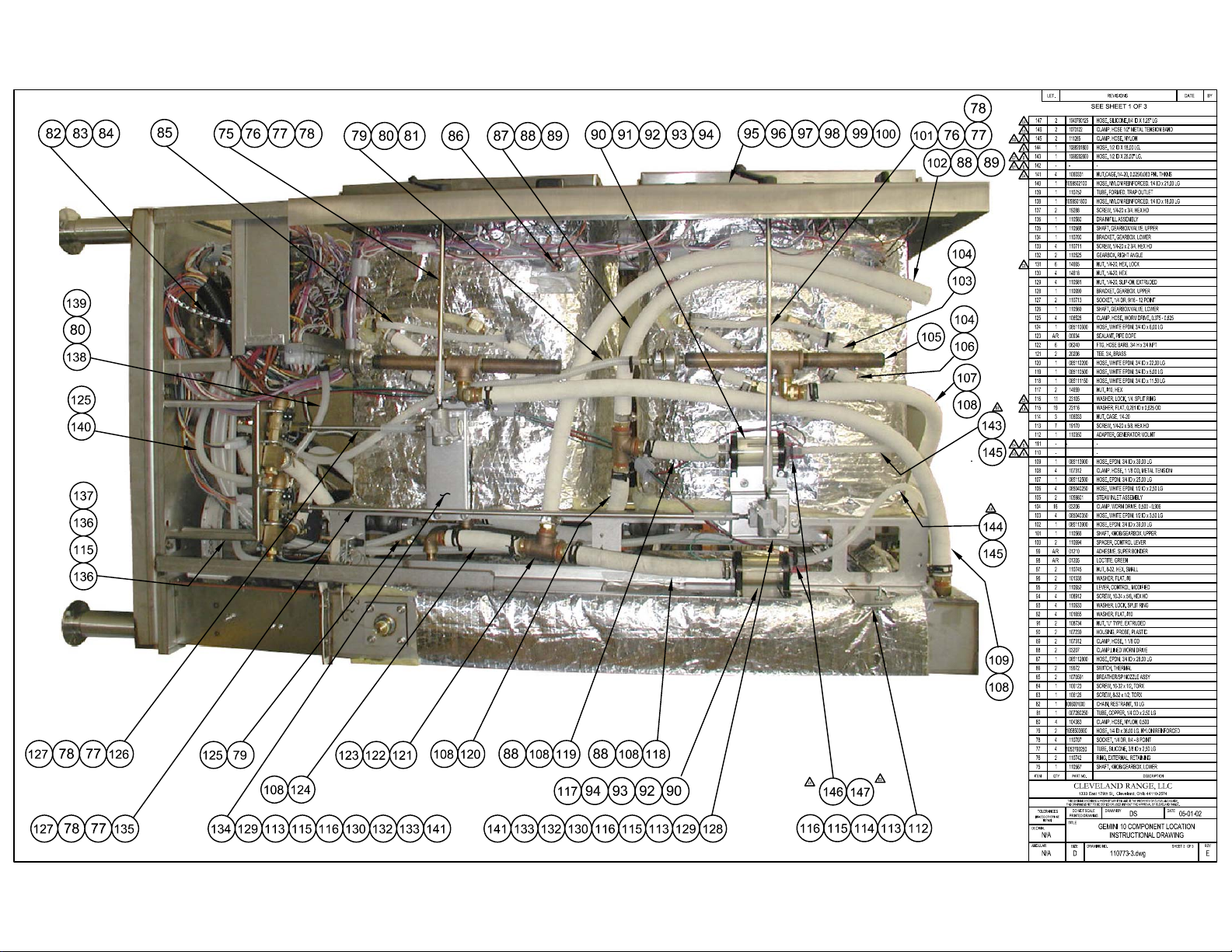
DRAWER
COMPONENT PARTS LIST
ITEM P/N DESCRIPTION
1
1057842
IGNITOR, NATURAL GAS
1057841
2
3
5
6
7
8
9
10
11
12
13
14
15
16
17
18
19
21
21A
22
23
262541350
27 19972 COMP. THERMOSTAT
28 109602
IGNITOR, PROPANE GAS
109877
GAS VALVE, NATURAL
1098771
GAS VALVE, PROPANE
IGNITION CONTROL MODULE
105693
205284
SPARK IGNITION TRANSFO RM E R
HI LIMIT CAPILLARY SWITCH
108995
300094
BLOWER W/ SENSOR (GEMINI 10)
110786 BLOWER W/ SENSOR (GEMINI 6)
108285
24VAC RELAY
105966
120VAC RELAY
107241
WATER LEVEL CONTROL BOARD
LEVEL CONTROL PROB E
107239
3 MINUTE INTERVAL TIMER
20478
106911
DESCALE TIMER
DESCALE INDICATOR / RESET SWITCH
19994
MANUAL DRAIN VALVE WITH SWITCHES
110613
FK300279 SWITCH ASSEMBLY (REPLACEMENT KIT)
STEAM CUTOFF SWITCH - SCS
108880
CONDENSER VALVE
22218
222231
FILL VALVE
12159
INDICATOR (RED)
TERMINAL BLOCK ASSEMBLY
108981
2030420
GROUND LUG
TERMINAL BLOCK SECTION (QTY. 2)
20301
20302
TERMINAL BLOCK END
108979
IGNITOR CABLE ASSEMBLY
110198
ELECTRO-MECHANICAL TIMER
TIMED / MANUAL SWITCH W / INDICATOR
30027824
20477 3 SECOND TIMER
BUZZER
INDICATOR (AMBER)
30015029 60 MINUTE TIMER
20
GRN
GND
WHT
21
21A
CUSTOMER
CONNECTIONS
120VAC
P300095 C
BLK
L1N
Page 22

GEMINI GAS - ELECTRONIC TIMER
CUSTOMER
OFF
ON
DESCALE
TIMER
3 MINUTE
TIMER
SW1
CONNECTION 120VAC
COMMON TO UPPER AND LOWER COMPARTMEN TS
243
1
6
587
3
2
1
POWER ON
R
BLK
NC
C
NO
SW2
TB
L1 N
OFF
ON
GND
DESCALE REQUIRED INDICAT O R
& RESET SWITCH
A
LL
NO NO
NO
C
NC
HEAT
FILL
H
N
VALVE
WATER
BOARD
FILL
CXL HI
PROBES
WHT
TRANSFORMER
FU
60 MINUTE
TIMER
MV
PV
24 VAC
TIMER
ELECTRONIC
3
2
1
R1
CNC
BLOWER
PROVER
COMPARTMENT
THERMOSTAT
NO
R2
NO
C
R1
CONDENSER
VALVE
R2
BLOWER MOTOR
M
MV
PV
TIMED
MANUAL
R
MANUAL
ON
TIMED
MAGNETIC
DOOR
SWITCH
(SCS)
GENERATOR
OVER TEMP
HI LIMIT
IGNITOR
GND SPARK CONTROL MOD GAS VALVE
MANUAL
TRANSFORMER
120V
24V
24V
24V
GND
SPARK
GND
MV/PV
SINGLE COMPARTMENT SHOWN
DUPLICATE FOR SECOND COMPARTMENT
L300096 C
Page 23

GEMINI GAS / ELECTRONIC TIMER
23
PAUSE
BLK
BLK
YELBLK
25
WHT YEL
11-3
11-2
RED
WHT/RED
9-7
ORN
27
WHT/RED
BLK
RED
BLK
18
WHT/RED
9-7
11-5
GRA
ORN
PS-4
24
PS-2
WHT/RED
PS-7 11-4
PRP
BLK
CNCNO
SW1
ON
C
NO
OFF
NC
SW2
GRA
BLK
BLU
13
9-3
9-2
9-8
GRA
PS-7
PS-2
BLU
7-6
7-4
7-5
PS-5
WHT/BRN
GRA
PS-3
14
26
PRP
11-6
11-1
BLU
BLU
ORN
28
PRP
11-6
BRN
2-14
BLU
PRP
12
TAN
TAN
PNK
21 3
7-1
7-2
7-3
LT BLU
PRP
WHT
BLK
PRP
362
1
4
5
7
8
2-13
2-12
2-11
2-10
BLK
3-14
ORN
15
GRA
YEL
4
WHT
24V (GND)
3-13
LT BLU
GND (BNR)
5
LT BLU
SPARK
3
MV/PV
9
ORN
WHT
BLU
YEL
PV/MV
24V
PV
MV
HEAT
MV
2
PV
FILL
BLU
WHT/ORN
ORN
GRN
GRN
4132765 89
GRN
PRP
PRP
RED
BLK
GRA
YEL
RED
C
HI
XL
H
N
YEL
YEL
BLU
WHT/ORN
YEL
GRN
RED
BLK
RED
WHT/RED
6
1
BLK
ORN
ORN
22
3-6
PNK
WHT/ORN
3-12
3-11
7
PRP
BLU
3-7
3-10
WHT/ORN
3-8
2-6
2-7
2-8
10
3-9
16
WHT
GRA
3-5
RED
R1
2-1
2-2
2-3
2-4
2-5
11
1 23
WHT/RED
WHT/RED
8
R2
PRP
WHT
GRA
YEL
17
WHT
LT BLU
3-2
3-1
3-4
YEL
ORN
RED RED
NOTES:
1. UPPER COMPARTMENT CIRCUIT SHOWN
DUPLICATE FOR LOWER COMMPARTMENT.
2. UNIT SHOWN IN THE OFF MODE WITH DRAIN
VALVE OPEN AND SWITCH 2 ACTUATED.
3-3
COMMON TO UPPER AND LOWER
WHT
WHT
W/R
WHT
COMPONENT
COMPARTMENTS
RED
CHASSIS
GROUND
DRAWER
WHT
W/R
WHT/RED
BLK
BLK
1-1
1-2
19
1-3
COMPONENT PARTS LIST
ITEM
10
11
12
13
14
15
17
18
19
20
21
21A
22
23
24
25
26
27
28
1
2
3
4
5
6
7
8
9
DESCRIPTION
P/N
IGNITOR, NATURAL GAS
1057842
IGNITOR, PROPANE GAS
1057841
GAS VALVE, NATURAL
109877
GAS VALVE, PROPANE
1098771
IGNITION CONTROL MODULE
105693
SPARK IGNITION TRANSFORMER
20528
HI LIMIT CAPI LLARY SWITCH
108995
BLOWER W/ SENSOR (GEMINI 10)
300094
BLOWER W/ SENSOR (GEMINI 6)
110786
24VAC RELAY
108285
120VAC RELAY
105966
WATER LEVEL CONTROL BOARD
107241
LEVEL CONTROL PROBE
107239
3 MINUTE INTERVAL TIMER
20478
DESCALE TIMER
106911
DESCALE INDICATOR / RESET SWITCH
19994
MANUAL DRAIN VALVE WITH SWITCHES
110613
FK300279 SWITCH ASSEMBLY (REPLACEMENT KIT)
STEAM CUTOFF SWITCH - SCS
108880
CONDENSER VALVE2221816
FILL VALVE
222231
12159
INDICATOR (RED)
TERMINAL BLO CK ASSEMBLY
108981
GROUND LUG
20304
TERMINAL BLOCK SECTION (QTY. 2)
20301
20302
TERMINAL BLOCK END
108979
IGNITOR CAB L E ASSEMBLY
ELECTRONIC TIMER
104389
TIMED / MANUAL SWITCH W / INDICATOR
300278
TRANSFORMER
104390
19972
COMP. THERMOSTAT
2AMP, 250V FUSE
106909
60 MINUTE TIMER
300150
BLK
WHT
21
21A
GRN
20
GND
L1N
CUSTOMER
CONNECTIONS
120VAC
P300096 C
Page 24

PROBLEM:
24CGA6
24CGA10.2
Steamer won't
steam with handle
in on position
Steamer won't
steam
Replace the
wiring to the
switch
Replace the
switch
Steamer won't
See
Steamer won't
ignite
Is there power to
the Timed/Manual
No
No
Is there power
from the Timed/
Manual switch?
Does the steamer
steam with the
door switch
bypassed?
Replace the
door switch
See
fill.
switch?
Yes
Yes
Yes
No
Is the red light on?
No
No
No
Is there water in
the sight glass?
Does the steamer
steam in manual
Is there 120 VAC
to the R2 relay?
Is there 24 VAC to
the main coil of the
Yes
Yes
Has the pilot
ignited?
Yes
mode?
Yes
Replace
the timer
Yes
Is the fan
turning?
Yes
gas valve?
Yes
Is there power to
No
the steamer?
replace the
on/off micro
No
No
No
Does the coil to
the main gas valve
get 24 VAC when
the fan prover
switch is
bypassed?
Yes
Adjust or
switch
the wiring
Is there 120 VAC
Replace
to relay
to the fan?
Yes
Replace
the fan
No
No
Connect power
to steamer.
No
Replace the R2
Check the
R1 relay
relay.
Replace the
gas valve?
Yes
Replace the
the fan prover
switch.
Page 25

PROBLEM:
24CGA6
24CGA10.2
Steamer won't fill
with the handle in
the on position
Steamer won't
fill
Is there power
to the steamer?
Yes
No
Connect
power to the
steamer
Adjust or
replace the on/
off micro switch
No
Is there water to
the steamer?
Yes
Is there 120 VAC
between the
terminals H and N
on the watr level
board?
Yes
Is there 120 VAC
between terminals
Fill and N on the
water board?
Yes
Is there 120 VAC
across the coil of
the fill solenoid?
Yes
No
No
No
Supply
water to the
steamer.
Adjust or
replace on/off
micro switch
With the wire
removed from the HI
terminal on the water
level board, is there
120 VAC between
terminals Fill and N?
Yes
Is there debris on
the HI probe in the
probe assy?
Yes
No
No
Replace the
water level
board.
Replace the
wire to the HI
probe.
Replace the fill
solenoid.
Clean or
replace the
drain valve.
No
No
Is water leaving
the fill solenoid?
Yes
Does the manual
drain valve close
completely?
Clean or
replace the
probe assy.
Yes
Page 26

PROBLEM:
24CGA6
24CGA10.2
Steamer won't
ignite
Steam generator
won't ignite
Is the red light on?
Yes
Is there power to
No No
the steamer?
Yes
Connect power
to the steamer
Clean or
replace the
probe assy.
Is there 120 VAC
between Heat and N
terminals on the water
No
level board with a
jumper between
terminal XL and C?
Replace water
level board.
Replace the
transformer
Replace the wires
to the ignition
module.
Replace the
ignition module
Steamer won't
Yes
See
fill
No
No
No
Is there water in
No
the sight glass?
Is there 120 VAC
No
terminals Heat and
N on the water
level board with
the the low probe
Is there 120 VAC
across the primary
of the 24 VAC
Is there 24 VAC to
the secondary of
Is there 24 VAC to
Is there spark from
the module until
the 90-second lock
Yes
between the
submerged?
yes
ignition
transformer?
Yes
the ignition
transformer?
Yes
the ignition
module?
Yes
out?
Yes
No
Does the pilot gas
Is spark generated
ground terminal on
Yes
Adjust or
replace the
on/off micro
switch
Replace
the high
limit
valve open when
the 24 VAC is
applied?
Yes
at the igniter?
Yes
Is there at least
1.0 micro amps
DC at the burner
the ignition
module?
Yes
Replace the
ignition module
No
No
No
Replace the
gas valve.
Replace the
igniter and
wire
Is the pilot flame
blue and
enveloping the
igniter?
Yes
Replace the
ground wire
No
Replace the
pilot assy
Supply gas to
the steamer
No
No
Is there 24 VAC to
the pilot coil on the
gas valve until the
90-second lock
out?
Yes
Does the steamer
have gas supplied?
Page 27

PROBLEM:
24CGA6, 24CGA10.2
Electronic timer displays "PAUS" and won't count down
START
Is steam heating
Replace the
thermo-switch
cabinetabove 192
degrees (the set
thermo-switch)?
Does the timer
count down when
Yes
the thermo-switch
the cooking
No
temp of the
Yes
No
is bypassed?
See
Steamer
won't steam
Replace the
electronic timer
START
Is COLD water
supplied to the
steamer?
Yes
Is the door gasket
physically
damaged?
Yes
Turn over the
gasket or
replace it.
No
No
Supply cold
water (35-60
PSI) to the
steamer.
Is the door out of
alignment?
Yes
Replace the
door bearings
and pins.
PROBLEM:
24CGA6, 24CGA10.2
Steam leaks around the door.
Is there 120 VAC
across the coil of
No
the condensate
solenoid?
Is the solenoid
Yes
opening?
No
Is the drain
obstructed?
Yes
Remove the
obstruction
No
No
Replace the
wiring to the
condensate
solenoid.
Replace the
condensate
solenoid.
Yes
Replace the
condensate spray
nozzle
Page 28

Descaling Procedure-SteamCraft Ultra and Gemini Series
How Much DISSOLVE to Use
Model Dissolve
Ultra 3 1/2 Gallon
Ultra 5 1 Gallon
Ultra 10 (Elec.) 1 Gallon (ea.)
Ultra 10 (Gas) 1½ Gallon
Gemini 6 & 10 1 Gallon (ea.)
1. Turn the unit OFF and open the
doors:
This will drain and rinse the generator for about
3 minutes.
2. Turn the unit power back On:
The generator will begin to refill with water.
3. Select Timed with the Timed/Manual
switch:
DO NOT start the timer, since you do not want
to heat the water during descaling. Leave the
doors open.
6. Let the descaler soak in generator for
approximately one hour:
7. After one hour, turn the unit power
This will drain and rinse the generator
Off:
for about 3 minutes.
4.
Remove descaling port cap and add
with the specified amount of
DISSLOVE:
Do this while the unit is refilling. The generators
can take-up to 8 minutes to refill.
After refill has stopped, add extra tap
5.
(See chart above)
water into the descaling port until
liquid is seen entering the cooking
cabinet.
coming out of the drain,
Adding extra water when descaling will raise the
descaling solution higher than the normal fill level,
allowing the DISSOLVE to work on sensors and
surfaces above the water line
Note: Some SteamCraft Ultra models (the
electric powered Ultra 10 and Gemini 6 and 10,
for example) have two generators and two
descaling ports. Both units should be descaled
at the same time, using this procedure
Note: Ultra 10 gas will have liquid
8. After the 3-minute drain cycle
completes, turn the unit back ON. After
the filling has stopped, add water until
liquid enters the cooking compartment (or
drain for the ultra 10 gas), and then turn
the unit OFF. This will drain and flush any
residue from the water level control
assembly. Replace descaling cap.
After the 3 minute drain cycle
9.
completes, Turn the unit ON and set
the Timer for 20 minutes:
Time/Manual switch is in the timed setting
and the doors are closed.
Make sure the
10. When the timer times out (after 20
minutes) turn the power Off:
This will drain and rinse the generator for
about 3 minutes.
This ends the descaling procedure. You can
now turn the unit back on and resume normal
startup and cooking operations.
 Loading...