

ClearSounds CL600 User Manual


Congratulations on your purchase of the CL600 Emergency
Connect Telephone from ClearSounds Communications™.
Please read this User Manual carefully in order to get the very
best results from your telephone. Keep the manual near the
telephone for easy reference.
Please visit our web site at www.clearsounds.com to:
· Register your product
It’s easy! Click on the Warranty Registration Tab, complete the form and click
“submit”. It’s that simple!
· Download additional manuals and troubleshooting tips
LIMITATION OF LIABILITY
By using this product, the purchaser agrees to the terms and conditions below and to read
and follow all instructions and warnings on the product and contained within the enclosed
manual.
It shall be the sole obligation of the purchaser to assure that CL600 Phone is installed and
programmed properly, and that the unit is used and maintained properly. This includes,
but is not limited to, periodic use to assure that the phone, including batteries, is in proper
working order, that the phone is located within sufficient range of the remote band to
provide reliable operation, and education of the user to assure that he/she is familiar with,
and capable of operating the phone and remote band.
The ClearSounds™ maximum liability hereunder is limited to the purchase price of the
product. In no event shall ClearSounds be held liable for any consequential, indirect,
incidental or special damages of any nature arising from the sale or use of the product,
including failure of equipment to perform, whether based in contract, tort, strict liability or
otherwise.
Further, ClearSounds has no obligation to assure that calls are placed, received or responded to, nor is ClearSounds responsible for the acts, or consequences of the acts, of
those responding.
Conditions for Use
IMPORTANT SAFETY INSTRUCTIONS
Read and understand the Installation Guide & User Manual. When using your telephone
equipment, basic safety precautions should always be followed to reduce the risk of fire,
electric shock and injury to person, including the following.
2

WARNING: The CL600 Emergency Connect Telephone should be tested regularly to
ensure proper delivery of your pre-recorded emergency message when activated by the
Emergency Button or the Remote Band. This is your responsibility as the user of the
product.
WARNING: Using the CL600 does not guarantee that you will make contact or receive
help. The CL600 is only an aid to assist you in calling for help.
WARNING: Certain structures within the household may block the transmitter signal. It
is up to the user to test the transmitter (Remote Band) within the first 30 days of use to
determine if any dead areas exist, and where they are located.
WARNING: Do not place the CL600 on any metal surface. It could reduce reception
range.
WARNING: The CL600 is capable of amplifying sounds to a loud volume. It is important to
instruct all potential users of its proper operation. It is advised to adjust the volume control
to the minimum level (Low) when not in use and alert other users that hearing damage can
potentially result from misuse.
WARNING: To avoid the possibility of electrical shock, do not use this product near water
(For example, near a bathtub, wash basin, kitchen sink or laundry tub, in a wet basement
or near a swimming pool) while in the bathtub or shower or when you are wet. If the phone
becomes submerged in water, do not attempt to retrieve it until after you have unplugged
the line cord from the modular wall jack. Do not plug the phone back in until it has dried
completely.
WARNING: Avoid using the telephone during electrical storms. There may be a remote
risk of electric shock from lightning. If the electrical storm is present in your immediate
area, possibility of electrical shock exists.
WARNING: Do not use the phone if you suspect a gas leak in the area. The phone’s
electrical contacts could create a spark, which could ignite any heavy concentration of
leaking gas.
WARNING: Do not use liquid cleaners or aerosol cleaners on the telephone. Use a damp
cloth for cleaning.
WARNING: The Remote Band is not waterproof or water resistant and may not be submerged in water.
IMPORTANT: Test Your CL600! You should check the operation of your CL600 Phone at
least once per month to assure that it is operating properly.
PLEASE SAVE THESE INSTRUCTIONS
3

Table of Contents
Product Overview Page 2
Limitation of Liability Page 2
Conditions For Use Page 2
Table of Contents Page 4
Features & Functions
Top View Page 6
Left side, Right side & Back side Views Page 7
Handset & Bottom View Page 8
LCD Screen Page 9
Screen Display Page 9
Installation Steps
Components Page 10
Installing the optional batteries Page 10
Phone mounting – desk & wall use Pages 11-12
Setting the dialing mode Page 12
Programming ringer – volume & style Pages 13-14
Programming memory dial buttons Pages 14-15
CL600 Emergency Connect Phone Operation
Programming 6 Emergency Connect SOS
dialing numbers Page 16
Record an Emergency Connect SOS message Pages 16-17
Play the Emergency Connect SOS message Page 17
Use the Emergency Connect function Page 17
Test the Emergency Connect phone Page 18
Cancel the Emergency Connect SOS call Page 18
Remote Audio Monitoring
Activate the Remote Audio Monitoring Pages 18-19
Setting Access PIN Code Page 19
Using the Remote Audio Monitoring Page 19
Auto On Hook Page 20
CL600 Phone Operation
Making & receiving a call
Using the handset Page 20
Using the speakerphone Pages 20-21
Using audio & telephone accessory jacks Pages 21-22
Using the amplification function Page 23
4

Using the volume reset override Page 24
Using the outgoing speech volume Page 25
Using the last number redial Page 25
Using the flash button Page 25
Using the mute button Page 25
CL600 Caller ID Operation
Viewing your Caller ID display Page 26
Viewing incoming calls Page 27
New calls / message waiting indicator Page 28
Remove call record(s) from Caller ID
A specific call record Page 28
All call records Pages 28-29
Turn on the Call Waiting Caller ID feature Page 29
CL600 Miscellaneous Feature Setting
Set language Page 30
Set area code / LDS code Page 30
LCD screen contrast Page 31
Date / Hour format Pages 31-32
Adjust number size Page 32
Phone book
Add new number/name Pages 32-33
Review /modify number/name Page 33
Delete number Pages 33-34
Save number from Caller ID Page 34
Dial from the phone book Page 34
Recall/Delete one of the last 30 numbers dialed Pages 34-35
Auto On Hook Page 35
Troubleshooting Guide Pages 35-36
Maintenance and Care Page 37
Change the Emergency Connect Band
Remote Battery Page 37
Specifications Page 38
FCC Regulatory Compliance Pages 38-39
Warranty and Service Page 40
5
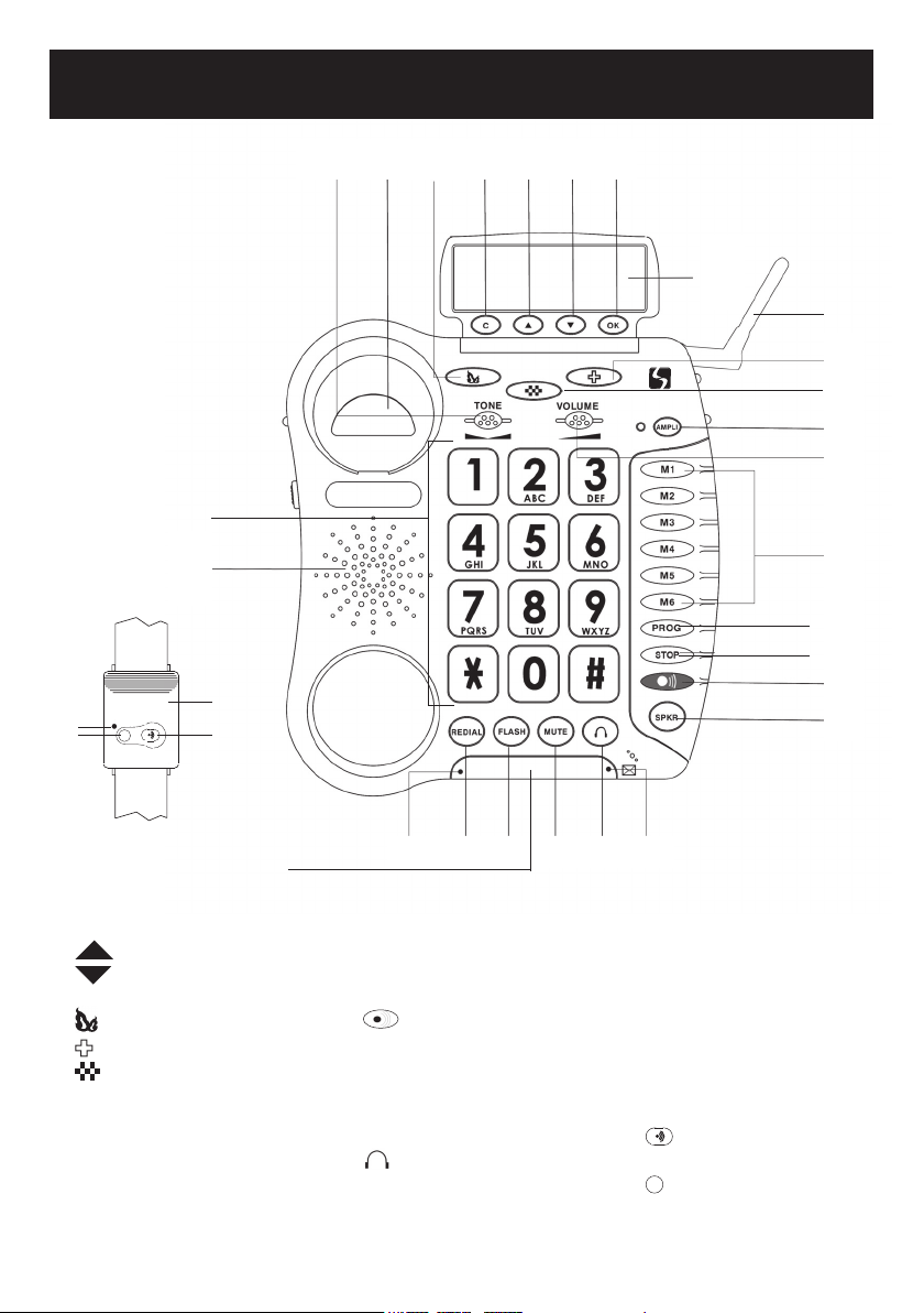
Features & Functions
31
30
Figure #2
X
25
24
28
29
432152611
27
8
6
7
9
10
12
13
14
15
16
Front
19
1. C (delete) button
2.
(up) button
3. (down) button
4. OK (accept) button
5.
– Priority memory button
6. – Priority memory button
7. - Priority memory button
8. Antenna
9. AMPLI – Amplification &
tone activation button
10. Volume control
11. Tone control
12. M1 – M6 One-Touch
memory dial buttons
6
13. PROG – Program (save)
button
14. STOP – Cancels emer-
gency connect dial button
15.
– Active emergency
connect dial button
16. SPKR – Speakerphone
button
17. New calls / message wait ing indicator
18. – Headset button
19. Flashing incoming call
indicator (strobe light)
20. MUTE button
171820212223
21. FLASH button
22. REDIAL button
23. In use indicator
24. Speaker
25. Large keypad
26. Hook switch
27. Caller ID Screen
28. Remote Band
29. – Active or Answer
button
30. X – Cancel or End Button
31. LED Stop/battery light
indicator

Features & Functions
Figure #3
2
Left side
3
4
5
1
Right side
Back
67891011
1. Speakerphone volume adjustment
2. Antenna
3. Outgoing speech volume select switch (LO/NORMAL/HI)
4. Ringer Volume select switch (HI/LO/OFF)
5. Ringer / shaker / strobe select mode
6. Phone line jack
7. AC power adapter jack
8. Volume reset override switch (ON/OFF)
9. Optional bed shaker jack
10. Optional Audio/Neckloop jack (3.5mm jack)
11. Optional Telephone jack (2.5mm hands-free)
7

Figure #4
Bottom
Handset
1234
1. Handset Boost button
2. Memory card to record speed dial numbers
3. Phone keyholes (mounts)
4. Battery compartment
8

Figure #5
1
9
8
Screen example (on hook position)
1. Hours
2. Minutes
3. Power network icon
4. Number of calls
7
6
5. Validation button
6. UP / DOWN arrow buttons
7. Cancel / Clear button
8. Month
9. Day
5
2
3
4
OK button is used to confirm action or a choice on the screen.
“UP / DOWN arrow” buttons are used to highlight or scroll through the menu.
C button is used to cancel or confirm an action/entry or clear a stored Caller ID call.
Your CL600 Phone has a screen with different icons, which help you to use the telephone
The telephone is powered by battery (+battery indicator).
The telephone is powered by AC adapter.
Memory storing is required.
Screen contrast level.
“Mute” is activated.
Speakerphone is activated.
Precede the CID call record number.
To show new records.
9

Installation Steps
Installation of your ClearSounds™ CL600 Emergency Connect Phone is easy. There are
some basic steps you need to take when you set-up your CL600 Emergency Connect
Phone for the first time.
1. Check parts list.
2. Install (4) AAA Alkaline batteries (not included). Batteries are necessary in case of
network power failure to save stored numbers in memory and are required for the
“Phone Book” use.
3. Choose desktop or wall mount.
4. Set the dialing mode.
5. Set ringer and auxiliary alert.
6. Program your memory dial buttons.
COMPONENTS
Check to be sure you have all items that come with your telephone. You should have a
REMOTE BAND, TELEPHONE BASE UNIT, TELEPHONE HANDSET, 6 ft LONG TELEPHONE LINE CORD, 8 inch SHORT TELEPHONE LINE CORD, HANDSET COIL CORD,
WALL PLATE ADAPTER, SCREWDRIVER, AC ADAPTER, AND OWNERS MANUAL
INSTALLING THE OPTIONAL BATTERIES
The batteries are necessary in case of network power failure to save stored numbers in
memory and are required for the “Phone Book” use.
1. Open the battery compartment door located on the bottom of your phone by unscrewing the battery compartment door and removing it from the bottom of your
phone (screwdriver provided).
2. Insert correctly 4 AAA alkaline batteries (purchased separately) in the battery compartment (See diagram #6). Be sure to observe battery polarity as imprinted on the
base of the compartment.
3. Replace the battery compartment door and screw back in place.
4. The batteries will last approximately 1 year before needing replacement.
DIAGRAM #6- Installing the batteries
NOTE: Always unplug the line cord before installing new batteries.
10

PHONE MOUNTING INSTALLATIONS
Choose a location for the CL600 Emergency Connect Telephone that is as central as
possible in the house, while providing access to a modular jack and an AC outlet. The
telephone may be placed on a shelf or table, or may be fixed to a wall using the mounting
bracket.
Plug the AC Adapter into the AC power back on the back of your phone, then into an
electrical outlet or surge protector, if you are using one. NOTE: The adapter is required
for the telephone to work correctly. If the adapter is accidentally unplugged (or in case
of power failure) and if the batteries are dead or not installed, minimal restricted phone
features only will work on the phone (make a call or answer incoming call).
IMPORTANT: Please remove the clear plastic Caller ID tab. This film tab is only for display
and to protect your Caller ID display during shipping.
Desk / Table Use
1. Connect one end of the 6ft telephone cord to the line jack on the back of your CL600
Phone and connect the other end to a modular phone jack (RJ11C).
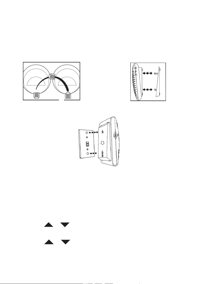
2. Connect the handset coil cord (curly cord) to the handset and to the telephone (See
diagram #7)
3. Lift the handset and listen for a dial tone. If you hear a dial tone, your phone is ready
to use. If there is no dial tone, check all your cords to make sure they are plugged
in securely.
.
DIAGRAM #7 – Desk Installation
Wall Mount Use
1. Slide the handset hanger tab out and reverse its position (rotate it 180 degrees).
Slide it back into place so that the hook points up (See diagram #8). This will keep
the handset from falling out of the cradle when it is mounted on the wall.
2. Plug the 8in short phone cord into the telephone jack on the CL600, run phone cord
underneath wall plate adapter and through the opening.
3. Insert the Wall Plate adapter. Hold the wall plate adapter so that the raised mounting
pins line up with the phone’s keyholes on the CL600. Once the holes are lined up,
push the wall plate adapter in towards the CL600 and then slide the plate upwards
until it is securely seated on the phone. (See diagram #9)
4. With the Wall Plate adapter installed, plug the 8in short phone cord into the jack on
the wall.
11
5. Holding the phone slightly above the mounting screws on the wall jack, push the
phone against the mounting screws so they are hooked into upper and lower keyhole slots on the back of the phone. Slowly slide the phone down until it snaps into
place (See diagram #10).
6. Connect the handset coil cord (curly cord) to the handset and to the telephone.
7. Lift the handset and listen for a dial tone. If you hear a dial tone, your phone is ready
to use. If there is no dial tone, check all your cords to make sure they are plugged in
securely.
DIAGRAM #8 – Reversing The Hook DIAGRAM #9 – Mounting The Wall Bracket
DIAGRAM #10 – Wall Installation
SETTING THE DIALING MODE
The Tone/Pulse is factory pre-set to Tone (T). Please check with your local telephone
company if uncertain of the type of service. You can review or change the settings as
follows:
In the hook position (handset in cradle),
1. Press the MUTE button to access the special features.
2. Using the
PHONE>>.
3. Press the OK (green) button.
4. Using the or arrow buttons, scroll to select <<TONE MODE OR PUSLE
MODE>>.
5. Press OK button.
6. Press the C button 3 times to exit.
12
or arrow buttons (below the Caller ID Display), highlight <<SET

PROGRAMMING THE RINGER & AUXILIARY ALERT
Ringer Volume:
You can adjust the ringer volume of your CL600 as high as 95+ dB. The ringer volume
adjustment is located on the right side of the telephone. The settings are OFF, LO, HI, (See
diagram #11)
can adjust the tone or melody of the ring.
. Your phone comes with the ringer switched to HI. In additional to volume, you
: Off,
: Low,
: Hi
DIAGRAM #11 – Ringer Volume Switch
Ring Style:
Your CL600 Phone allows you to choose from four different ring tones. You can choose a
new one by changing the settings as follows:
In the hook position
1. Press the MUTE button to access the special features (See diagram #12).
2. Using the or arrow buttons (below the Caller ID Display), highlight <<SET
PHONE>>.
3. Press the OK (green) button.
4. Using the or arrow buttons, scroll to select <<SET RING>>.
5. Press OK button.
6. There are four (4) ring tones available. To hear each ring, use the or
arrow button to highlight any one of the four and then press the OK button. Do this
with each one to find the best fit for you.
7. To save the ring tone, highlight the ring tone you want, and then press the C button
three (3) times until you are back to the time and date display. Or after your selection, do nothing for 20 seconds and the ring type will automatically be saved for the
next incoming call.
DIAGRAM #12 – Set The Ringer
Strobe & Optional Bed Shaker Ring Signaling:
Your ClearSounds™ CL600 Emergency Connect Telephone incorporates several options
to alert you that the phone is ringing. The loud, adjustable Ringer as well as the bright
Strobe and optional Bed Shaker or any combination of these allow you to customize the
phone to fit your needs.
13
 Loading...