


 Loading...
XAP™ 400 Audio Conferencing System
Installation & Operation Manual

ii
© 2002 ClearOne Communications, Inc. All rights reserved. No part of this document may be reproduced in any form or by any means without written permission from ClearOne Communications. Printed in the United States of America. ClearOne Communications reserves specific privileges. Information in this document is subject to change without notice.
XAP 400 Installation and
Operation Manual
ClearOne Part No. 800-151-
201 July 2002 (Rev.2.1)
Technical Services Group ~ 1-800-283-5936 (USA) ~ 1-801-974-3760

iii
XAP 400 Insta llation |
an d Operati on Manual |
Table of Contents |
|
CHAPTER 1: Introduction . . . . . . . . . . . |
. . . . . . . . . . . . . . .1 |
Features . . . . . . . . . . . . . . . . . . . . . . . . . . . . . . . . . |
. . . . . . . . . . . . . . . . . . .1 |
Professional Services Group . . . . . . . . . . . . . . . . . . |
. . . . . . . . . . . . . . . . . . .2 |
Product registration . . . . . . . . . . . . . . . . . . . |
. . . . . . . . . . . . . . . . . .3 |
Product returns . . . . . . . . . . . . . . . . . . . . . . . |
. . . . . . . . . . . . . . . . . .3 |
Unpacking . . . . . . . . . . . . . . . . . . . . . . . . . . . . . . . |
. . . . . . . . . . . . . . . . . . .3 |
Controls and Connections . . . . . . . . . . . . . . . . . . . . |
. . . . . . . . . . . . . . . . . . .4 |
Front panel . . . . . . . . . . . . . . . . . . . . . . . . . . |
. . . . . . . . . . . . . . . . . .4 |
Rear panel . . . . . . . . . . . . . . . . . . . . . . . . . . |
. . . . . . . . . . . . . . . . . .5 |
Networking . . . . . . . . . . . . . . . . . . . . . . . . . . . . . . . |
. . . . . . . . . . . . . . . . . . .6 |
Expansion bus . . . . . . . . . . . . . . . . . . . . . . . |
. . . . . . . . . . . . . . . . . .6 |
Operational Requirements . . . . . . . . . . . . . . . . . . . . |
. . . . . . . . . . . . . . . . . . .7 |
Power . . . . . . . . . . . . . . . . . . . . . . . . . . . . . |
. . . . . . . . . . . . . . . . . .7 |
Telephone line . . . . . . . . . . . . . . . . . . . . . . . |
. . . . . . . . . . . . . . . . . .7 |
Equipment placement . . . . . . . . . . . . . . . . . . |
. . . . . . . . . . . . . . . . . .8 |
Environmental . . . . . . . . . . . . . . . . . . . . . . . |
. . . . . . . . . . . . . . . . . .8 |
CHAPTER 2: Installation . . . . . . . . . . . . |
. . . . . . . . . . . . . . .9 |
Hardware Setup . . . . . . . . . . . . . . . . . . . . . . . . . . . |
. . . . . . . . . . . . . . . . . . .9 |
To connect the unit . . . . . . . . . . . . . . . . . . . . |
. . . . . . . . . . . . . . . . . .10 |
Networking Units . . . . . . . . . . . . . . . . . . . . . . . . . . |
. . . . . . . . . . . . . . . . . . .11 |
Expansion bus connections . . . . . . . . . . . . . . . |
. . . . . . . . . . . . . . . . . .11 |
Device IDs . . . . . . . . . . . . . . . . . . . . . . . . . . |
. . . . . . . . . . . . . . . . . .12 |
Mixer mode . . . . . . . . . . . . . . . . . . . . . . . . . |
. . . . . . . . . . . . . . . . . .12 |
LCD Programming . . . . . . . . . . . . . . . . . . . . . . . . . |
. . . . . . . . . . . . . . . . . . .13 |
LCD menu tree . . . . . . . . . . . . . . . . . . . . . . . |
. . . . . . . . . . . . . . . . . .13 |
System menu . . . . . . . . . . . . . . . . . . . . . . . . . |
. . . . . . . . . . . . . . . . . .14 |
RS-232 menu . . . . . . . . . . . . . . . . . . . . . . . . |
. . . . . . . . . . . . . . . . . .15 |
Meter menu . . . . . . . . . . . . . . . . . . . . . . . . . |
. . . . . . . . . . . . . . . . . .16 |
Inputs menu . . . . . . . . . . . . . . . . . . . . . . . . . |
. . . . . . . . . . . . . . . . . .18 |
Outputs menu . . . . . . . . . . . . . . . . . . . . . . . . |
. . . . . . . . . . . . . . . . . .18 |
Technical Services Group ~ 1-800-283-5936 (USA) ~ 1-801-974-3760

iv
CHAPTER 3: System Configuration . . . . . . . . . . . . . . . . . . |
.21 |
G-Ware Requirements . . . . . . . . . . . . . . . . . . . . . . . . . . . . . . . . . . . . . . . . . |
.21 |
Creating floppy disk copies . . . . . . . . . . . . . . . . . . . . . . . . . . . . . . . . |
22 |
Installing G-Ware . . . . . . . . . . . . . . . . . . . . . . . . . . . . . . . . . . . . . . . . . . . . . |
22 |
Site Setup . . . . . . . . . . . . . . . . . . . . . . . . . . . . . . . . . . . . . . . . . . . . . . . . . . . |
23 |
Creating a new site . . . . . . . . . . . . . . . . . . . . . . . . . . . . . . . . . . . . . . |
23 |
Adding a XAP 400 . . . . . . . . . . . . . . . . . . . . . . . . . . . . . . . . . . . . . . |
24 |
Configuring Unit Properties . . . . . . . . . . . . . . . . . . . . . . . . . . . . . . . . |
25 |
G-Ware Screens . . . . . . . . . . . . . . . . . . . . . . . . . . . . . . . . . . . . . . . . . . . . . . |
27 |
Flow Screen . . . . . . . . . . . . . . . . . . . . . . . . . . . . . . . . . . . . . . . . . . . |
27 |
Matrix Screen . . . . . . . . . . . . . . . . . . . . . . . . . . . . . . . . . . . . . . . . . . |
27 |
Audio Routing . . . . . . . . . . . . . . . . . . . . . . . . . . . . . . . . . . . . . . . . . . . . . . . . |
30 |
Expansion bus O—Z routing . . . . . . . . . . . . . . . . . . . . . . . . . . . . . . . . |
30 |
Process A—D routing . . . . . . . . . . . . . . . . . . . . . . . . . . . . . . . . . . . . . |
30 |
Cross point attenuation . . . . . . . . . . . . . . . . . . . . . . . . . . . . . . . . . . . |
30 |
Matrix report . . . . . . . . . . . . . . . . . . . . . . . . . . . . . . . . . . . . . . . . . . |
31 |
Inputs and outputs . . . . . . . . . . . . . . . . . . . . . . . . . . . . . . . . . . . . . . . . . . . . |
32 |
Inputs 1—4 . . . . . . . . . . . . . . . . . . . . . . . . . . . . . . . . . . . . . . . . . . . . |
32 |
Inputs 5—8 . . . . . . . . . . . . . . . . . . . . . . . . . . . . . . . . . . . . . . . . . . . . |
44 |
Outputs 1—9 . . . . . . . . . . . . . . . . . . . . . . . . . . . . . . . . . . . . . . . . . . . |
46 |
Expansion Buses . . . . . . . . . . . . . . . . . . . . . . . . . . . . . . . . . . . . . . . . . . . . . . |
48 |
From Expansion Bus O—Z . . . . . . . . . . . . . . . . . . . . . . . . . . . . . . . . . |
48 |
To Expansion Bus O—Z . . . . . . . . . . . . . . . . . . . . . . . . . . . . . . . . . . . |
48 |
Processing . . . . . . . . . . . . . . . . . . . . . . . . . . . . . . . . . . . . . . . . . . . . . . . . . . |
49 |
Processing A—D . . . . . . . . . . . . . . . . . . . . . . . . . . . . . . . . . . . . . . . . . |
49 |
Telco Setup . . . . . . . . . . . . . . . . . . . . . . . . . . . . . . . . . . . . . . . . . . . . . . . . . . |
55 |
To configure telco settings . . . . . . . . . . . . . . . . . . . . . . . . . . . . . . . . . |
55 |
Telco Transmitand Receive . . . . . . . . . . . . . . . . . . . . . . . . . . . . . . . . . . . . . . |
57 |
Telco Transmit . . . . . . . . . . . . . . . . . . . . . . . . . . . . . . . . . . . . . . . . . . |
57 |
Telco Receive . . . . . . . . . . . . . . . . . . . . . . . . . . . . . . . . . . . . . . . . . . . |
58 |
CHAPTER 4: Advanced Configuration . . . . . . . . . . . . . . . . . |
59 |
Presets . . . . . . . . . . . . . . . . . . . . . . . . . . . . . . . . . . . . . . . . . . . . . . . . . . . . .59
Overview . . . . . . . . . . . . . . . . . . . . . . . . . . . . . . . . . . . . . . . . . . . . . .59
Creating Presets . . . . . . . . . . . . . . . . . . . . . . . . . . . . . . . . . . . . . . . .59
Running presets . . . . . . . . . . . . . . . . . . . . . . . . . . . . . . . . . . . . . . . . .64
Technical Services Group ~ 1-800-283-5936 (USA) ~ 1-801-974-3760

v
Running multiple presets simultaneously . . . . . . . . . . . . . . . . . . . . . |
.64 |
Macros . . . . . . . . . . . . . . . . . . . . . . . . . . . . . . . . . . . . . . . . . . . . . . . . . . . . |
.67 |
Creating macros . . . . . . . . . . . . . . . . . . . . . . . . . . . . . . . . . . . . . . . . |
67 |
Editing macros . . . . . . . . . . . . . . . . . . . . . . . . . . . . . . . . . . . . . . . . . . |
69 |
Running macros . . . . . . . . . . . . . . . . . . . . . . . . . . . . . . . . . . . . . . . . . |
70 |
CHAPTER 5: Operation . . . . . . . . . . . . . . . . . . . . . . . . . . . . |
71 |
Using the XAP 400 . . . . . . . . . . . . . . . . . . . . . . . . . . . . . . . . . . . . . . . . . . . |
71 |
To answer a call . . . . . . . . . . . . . . . . . . . . . . . . . . . . . . . . . . . . . . . . |
71 |
To make and disconnect a call . . . . . . . . . . . . . . . . . . . . . . . . . . . . . |
71 |
Using the Dial interface . . . . . . . . . . . . . . . . . . . . . . . . . . . . . . . . . . . . . . . . |
72 |
To make and disconnect a call . . . . . . . . . . . . . . . . . . . . . . . . . . . . . . |
72 |
To dial multiple numbers . . . . . . . . . . . . . . . . . . . . . . . . . . . . . . . . . . |
72 |
To mute . . . . . . . . . . . . . . . . . . . . . . . . . . . . . . . . . . . . . . . . . . . . . . . |
72 |
Touch-tone dialing . . . . . . . . . . . . . . . . . . . . . . . . . . . . . . . . . . . . . . . |
73 |
Utilities . . . . . . . . . . . . . . . . . . . . . . . . . . . . . . . . . . . . . . . . . . . . . . . . . . . . |
74 |
Signal Generator . . . . . . . . . . . . . . . . . . . . . . . . . . . . . . . . . . . . . . . . |
74 |
Document Compare Utility . . . . . . . . . . . . . . . . . . . . . . . . . . . . . . . . |
75 |
Print Reports . . . . . . . . . . . . . . . . . . . . . . . . . . . . . . . . . . . . . . . . . . |
78 |
Copy and paste settings . . . . . . . . . . . . . . . . . . . . . . . . . . . . . . . . . . . |
78 |
GFirm Firmware Upgrade . . . . . . . . . . . . . . . . . . . . . . . . . . . . . . . . . |
79 |
G-Ware Switcher . . . . . . . . . . . . . . . . . . . . . . . . . . . . . . . . . . . . . . . . |
81 |
Message Log . . . . . . . . . . . . . . . . . . . . . . . . . . . . . . . . . . . . . . . . . . . |
82 |
Monitoring views . . . . . . . . . . . . . . . . . . . . . . . . . . . . . . . . . . . . . . . . . . . . . |
83 |
Gate View . . . . . . . . . . . . . . . . . . . . . . . . . . . . . . . . . . . . . . . . . . . . . |
83 |
Meter Views . . . . . . . . . . . . . . . . . . . . . . . . . . . . . . . . . . . . . . . . . . . |
83 |
Telco meters . . . . . . . . . . . . . . . . . . . . . . . . . . . . . . . . . . . . . . . . . . . |
84 |
CHAPTER 6: Control . . . . . . . . . . . . . . . . . . . . . . . . . . . . . |
87 |
GPIO Builder . . . . . . . . . . . . . . . . . . . . . . . . . . . . . . . . . . . . . . . . . . . . . . . . |
87 |
Control/Status A . . . . . . . . . . . . . . . . . . . . . . . . . . . . . . . . . . . . . . . . |
87 |
Remote Builder . . . . . . . . . . . . . . . . . . . . . . . . . . . . . . . . . . . . . . . . . . . . . . . |
88 |
XAP IR Remote . . . . . . . . . . . . . . . . . . . . . . . . . . . . . . . . . . . . . . . . |
88 |
ClearOne Control Panels . . . . . . . . . . . . . . . . . . . . . . . . . . . . . . . . . . |
89 |
RS-232 Port . . . . . . . . . . . . . . . . . . . . . . . . . . . . . . . . . . . . . . . . . . . . . . . . . |
92 |
Remote modem access . . . . . . . . . . . . . . . . . . . . . . . . . . . . . . . . . . . . |
92 |
Technical Services Group ~ 1-800-283-5936 (USA) ~ 1-801-974-3760

vi
Serial commands . . . . . . . . . . . . . . . . . . . . . . . . . . . . . . . . . . . . . . . .92 Command strings . . . . . . . . . . . . . . . . . . . . . . . . . . . . . . . . . . . . . . . .93
APPENDICES . . . . . . . . . . . . . . . . . . . . . . . . . . . . . . . . . .95
Appendix A: Specifications . . . . . . . . . . . . . . . . . . . . . . . . . . . . . . . . . . . . . .95 Appendix B: Pinouts . . . . . . . . . . . . . . . . . . . . . . . . . . . . . . . . . . . . . . . . . . .97 Appendix C: Control Panel . . . . . . . . . . . . . . . . . . . . . . . . . . . . . . . . . . . . . .101 Appendix D: Accessories . . . . . . . . . . . . . . . . . . . . . . . . . . . . . . . . . . . . . . . .103 Appendix E: Serial Commands . . . . . . . . . . . . . . . . . . . . . . . . . . . . . . . . . . .104 Appendix F: Warranty . . . . . . . . . . . . . . . . . . . . . . . . . . . . . . . . . . . . . . . . .146 Appendix G: Compliance . . . . . . . . . . . . . . . . . . . . . . . . . . . . . . . . . . . . . . . .148
Glossary . . . . . . . . . . . . . . . . . . . . . . . . . . . . . . . . . . . . . . . . . . . . . . . . . . . .152 Index . . . . . . . . . . . . . . . . . . . . . . . . . . . . . . . . . . . . . . . . . . . . . . . . . . . . . .162
Technical Services Group ~ 1-800-283-5936 (USA) ~ 1-801-974-3760

CHAPTER 1: Introduction
Congratulations on purchasing the XAP™ 400 Audio Conferencing System. The XAP 400 combines a highly advanced eight-by-eightdigital matrix mixer that features Gentner® Distributed Echo Cancellation®, noise cancellation, and audio processing with a single-line digital telephone hybrid. This combination provides the highest quality audio for a variety of audio and video conferencing applications–all in a single one-rack unit.
Features
•Gentner Distributed Echo Cancellation–four microphone/line echo cancellers remove echo in even the most difficult environments.
•EC Reference summing enables the XAP 400 to reference various signals for an echo cancellation reference without requiring a dedicated output.
•Noise cancellation reduces background noise such as that caused by fans or air conditioning.
•Four independent processing blocks, each with 15 filters, delay, and compressors, provide pinpoint audio configuration.
•Four mic/line inputs, four line inputs, and eight outputs.
•Enhanced expansion bus provides network capabilities. Eight XAP 400s or XAP 800s can be networked for up to 64 microphone inputs.
•Fully configurable matrix which allows you to route any input to any output or combination of outputs.
•Front panel control of mute and gain on inputs and outputs.
•Safety mute button on the toolbar that mutes all outputs if feedback occurs during the configuration process.
•ClearOne’s 100% digital signal processing (DSP) technology ensures crystal-clear audio with the deepest, most reliable hybrid null.
•International configuration of telephone hybrid setting
•Built-in telephone interface with:
~Telco noise cancellation
~Touch-tone dialing capability (40 character dial string)
~Full-time telco echo cancellation with 31 millisecond tail time
Technical Services Group ~ 1-800-283-5936 (USA) ~ 1-801-974-3760

2 |
|
Introduction ~ Professional Services Group |
|
~Selectable caller automatic level control (ALC)
~Adjustable dial tone, DTMF attenuation
~Continual adaptation to telephone line conditions
~Digital anti-alias filter minimizes hum and Central Office switching noise
~Analog telephone line compatibility
•10W speaker amp output.
•Program and operate with a connected PC or any other type of serial remote control device via expansion bus or RS-232 port.
Professional Services Group
If you need any additional information on how to install, set up, or operate your system, please contact us at one of the locations listed below. We welcome and encourage your comments so we can continue to improve our products and serve your needs.
ClearOne Communications ~ 1825 Research Way ~ Salt Lake City, Utah 84119
Technical Support
Telephone: |
1.800.283.5936(USA) or 1.801.974.3760 |
Fax: |
1.801.977.0087 |
E-mail: |
tech.support@clearone.com |
Web site: |
www.clearone.com |
Sales and Customer Service |
|
Telephone: |
1.800.945.7730 (USA) or 1.801.975.7200 |
Fax: |
1.800.933.5107 (USA) or 1.801.977.0087 |
E-mail: |
sales@clearone.com |
ClearOne Communications EuMEA GmbH
Leonhardstr.16-18, D-90443 Nuremberg, Germany |
||
Telephone: |
+49 |
911 955159-0 |
Fax: |
+49 |
911 955159-10 |
E-mail: |
global@clearone.com |
|
Technical Services Group ~ 1-800-283-5936 (USA) ~ 1-801-974-3760
Introduction ~ Unpacking
Product registration
Please register your XAP 400 online by visiting ClearOne Technical Support at www.clearone.com. When your product is properly registered, ClearOne Communications is better able to serve you should you require technical assistance. Registration information is also used to notify you of upgrades and new product information.
Product returns
All product returns require a return authorization (RA) number. Please contact ClearOne Technical Support before attempting to return your XAP 400 unit.
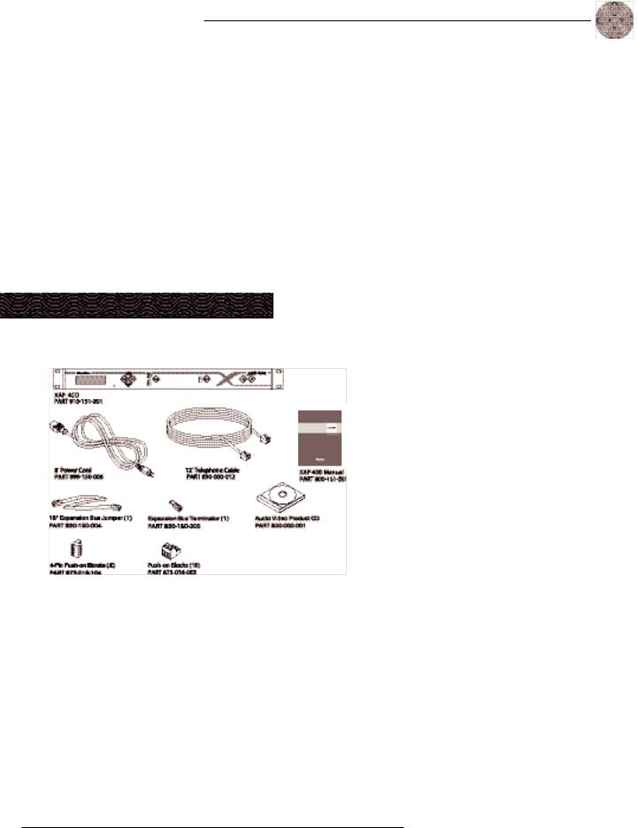
Unpacking
Ensure that the following items were received with your shipment:
Figure 1.1. Equipment included with XAP 400 unit
3
! |
ClearOne is not responsible |
|
for |
product damage |
|
incurred during shipment. |
||
You must make claims directly with the carrier. Inspect your shipment carefully for obvious signs of damage. If the shipment appears to be damaged, retain the original boxes and packing material for inspection by the carrier. Contact your carrier immediately.
Technical Services Group ~ 1-800-283-5936 (USA) ~ 1-801-974-3760

4
Figure 1.2. XAP 400 front-panel controls
Introduction ~ Controls and Connections
Controls and Connections
Front panel
The XAP 400 front-panel controls perform the following functions:
A.LCD. The LCD is used for numeric display of audio levels, gain readouts, and limited set-up and programming functions. See page 13.
B.Enter/ /ESC. These buttons are used to navigate the XAP 400’s menu system.
C.LED Meter. The LED bar meter is displays the audio level of a selected input, output, or processing channel of the XAP 400. The audio level of Output 8 is displayed by default. See page 16.
D.Meter. The Meter button takes you directly to the Meter branch of the XAP 400’s LCD programming tree. See page 16.
E.Mic On LED. These LEDs indicate microphone gate status.
F.On LED/button. The bicolor LED on the button illuminates green when the hybrid is on. The On button connects the XAP 400 to the telephone line and automatically adapts the hybrid to the line. Pressing and holding the On button for more than a half-second while the hybrid is active will readapt the hybrid to the telephone line.
G.Off LED/button. The bicolor LED on the button illuminates red when the hybrid is off. The Off button disconnects the hybrid from the telephone line.
Technical Services Group ~ 1-800-283-5936 (USA) ~ 1-801-974-3760
Introduction ~ Controls and Connections
Rear panel
The XAP 400 rear-panel connectors perform the following functions:
A.Power. The AC power cord input is a IEC type connector allowing 100—240VAC, 50/60Hz.
B.Inputs 1—4. These Phoenix-type connection blocks are for mic and/or line level inputs.
C.Outputs 1—8. These Phoenix-type connection blocks are for line level outputs that may be configured for any combination of gated and non-gated inputs, as well as a mix of mic and line level inputs.
D.Inputs 5—8. These Phoenix-type connection blocks are for line level inputs.
E.Expansion Bus In, Out. This RJ-45 connector is used to connect XAP units. G-Ware is capable of accessing and controlling an expansion bus network of up to eight XAP 400/800/PSR1212 units and 16 XAP TH2 units, where the total number of microphone inputs does not exceed 64. The expansion bus supports a distance of up to 80 feet between each connected XAP 400/800 or PSR1212.
F.RS-232. This female DB9 serial port connects the XAP 400 to a PC, modem, or other custom remote controller. For serial commands, see page 104.
G.Control/Status Ports A and B. These two female DB25 connectors are for general purpose input/output (GPIO) control of custom or unique control devices. The control devices access the command set for the XAP 400 and can be used for common functions such as volume control, muting, preset changes, room combining, etc. Devices can be connected to either port.
For instructions on how to program the control and status pins, see the GPIO section on page 87. The default settings allow control and status of inputs, outputs, volume, and presets. These pins are active low. For pinout and default information, see Appendix B.
5
Figure 1.3. XAP 400 rear-panel connectors
Technical Services Group ~ 1-800-283-5936 (USA) ~ 1-801-974-3760

6
The latency or propagation delay is <1ms.
Introduction ~ Networking
H.Speaker. This is a 10W power amp connector. A 4—16ž speaker can be directly connected to the XAP 400, eliminating the need for an external power amplifier.
I.Telco Line. This RJ-11 connector provides connection of a standard analog telephone line to the hybrid.
J.Telco Set. This RJ-11 connector allows connection to a standard telephone set. Tip and ring from the phone line are present at this connector when the hybrid is off. Tip and ring from the phone line are not present at this point when the hybrid is on.
K.RS-485 Remote Panel A/B Port. These four-pin Phoenix connector ports allow you to control the XAP 400 with the ClearOne Control Panel or XAP IR Remote.
Power is supplied through the RS-485 ports to the remote Control Panels from the XAP 400. This power is limited to a total of 300mA at 15 volts for each connector. Over-current protection is provided on the +15V pins to prevent damage in the event of shorting. External power can be provided to control devices when more current is required. See page 102 for maximum cable run distances when using ClearOne Control Panels.
Networking Expansion bus
The digital mix-minus expansion bus (RJ-45 LAN) is used to connect up to eight XAP 800/400s and 16 XAP TH2 units, where the total number of microphone inputs does not exceed 64. The maximum distance between interconnected XAP 800/400 or PSR1212 units is 80 feet (24 meters). Connecting a XAP TH2 must not increase the cable length between two PSR1212s, XAP 800s and/or XAP 400s beyond 80 feet. ClearOne recommends that category five twisted-pair (10BaseT LAN) cable be used.
The expansion bus (E-bus) allows audio routing between destinations on the E-bus network. The E-bus contains 12 independent digital audio buses labeled O—Z which can route mic or line level inputs in any combination across the E-bus network. The O—Z buses are divided into two groups (O—R and S—Z) based on their capabilities and default settings. The E-bus also contains four PA adapt/acoustic echo cancellation reference buses, four global gating buses, and one control bus.
•O—R buses. These four audio buses are defaulted as the mic mix buses; they can communicate the NOM count and mic mixing parameters across the
Technical Services Group ~ 1-800-283-5936 (USA) ~ 1-801-974-3760

Introduction ~ Operational Requirements |
|
7 |
|
network to other XAP 400s. All gated mics are routed to the 0-bus by default.
•S—Z buses. These eight buses are defaulted as auxiliary mix buses. They are used to route auxiliary audio, such as from a CD playe r or VCR, to and from other units on the network. These buses are also used as mic mix buses when NOM count is not required.
•PA Adapt/Acoustic Echo Cancellation Reference buses. These buses allow an input from a XAP 400 to reference an output on another linked XAP 400/800. See PA Adapt and AEC Reference on page 33 for more information.
•Global Gating Groups A-D buses. These mix-minus buses are defined as microphone gating groups which support first-mic priority, maximum number of mics, etc. and work across all linked XAP 400/800s. Unlike the audio buses, they contain only mic status and gat e parameters. See page 41 for more information about gating groups.
•Control bus. The control bus is an independent channel from the E-bus’s audio channel; it uses a different pair of wires on the same E-bus cable. This allows control information to pass even if the units are not using the audio
Operational Requirements Power
The XAP 400 automatically accommodates voltage requirementsof 100—240VAC, 50/60Hz, 15W.
Telephone line
The XAP 400 model operates on a standard analog telephone line and connects to the telephone system with a standard RJ-11C modular jack. If you do not have an RJ-11C jack where you want to install your XAP 400, call your telephone company for installation.
The XAP 400 can be configured to meet compliance requirements of different countries via the G-Ware software. See page 2 5.
! |
Warning: The country code |
||
must be s |
et correctly i n |
||
G-Ware to ensure that the |
|||
unit operates pr |
operly when |
|
|
connected to the telco network and |
|
||
that it complie s with the country’s |
|
||
telco |
requirements. Changi ng thi s |
||
code to a coun try other than the |
|
||
intended country of operation might |
|||
cause the XAP 400 to be non |
- |
||
compliant. |
|
|
|
Technical Services Group ~ 1-800-283-5936 (USA) ~ 1-801-974-3760

8 Introduction ~ Operational Requirements
Equipment placement
The XAP 400 models are designed for installation in a standard 19-inch equipment rack. You canalso purchase side panels for desktop placement. See Appendix D for a list of accessories.
Environmental
The XAP 400 can be safely operated in a room with varying temperatures between 32 °F/0 °C and 110 °F/43 °C.
Technical Services Group ~ 1-800-283-5936 (USA) ~ 1-801-974-3760
CHAPTER 2: Instal lation
The XAP 400 is designed for easy installation and setup. All connections are made through rear-panel connectors. This chapter provides instructionson installing the units and making initial connections, creating an expansion bus (E-bus) network, assigning device ID numbers, selecting the mixer mode, and using the LCD menu.
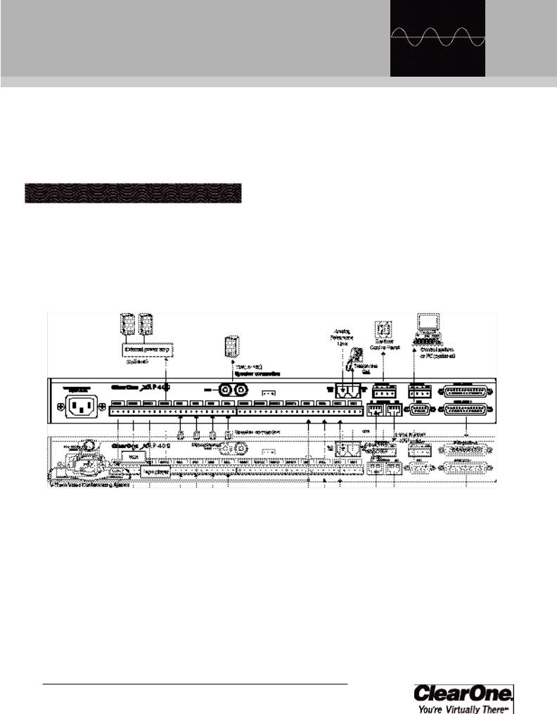
Hardware Setup
The diagram below illustrates the typical connections that are made for a single-unit XAP 400 system. The default routing settings in the G-Ware Matrix Screen allow the XAP 400 to work out of the box for this type of installation.
Figure 2.1. XAP 400 installation diagram
Technical Services Group ~ 1-800-283-5936 (USA) ~ 1-801-974-3760

|
|
|
10 |
|
Installation ~ Hardware Setup |
|
||
|
|
|
Figure 2.2. XAP 400 rear-panel connectors
|
The th ree terminals in |
||
the |
Phoenix con |
nector |
|
|
correspond with the rear- |
||
panel audio |
contacts (from |
left to |
|
right): + ( positive), — (negative), |
|||
and |
(ground). |
|
|
Figure 2.3. Phoenix push-on connector
To connect the unit
1.Place the unit in a standard 19-inch rack and attach it securely.
2.Connect your telephone line from the wall jack to the RJ-11C Line jack [I].
3.Plug your telephone set into the RJ-11C Set jack [J].
4.If you are using a custom controller for control and status, plug it into the DB25 Control/Status A or B port [G].
If you are using an e xternal RS-232 controller, connect it to the RS-232 port [F].
5.Wire the inputs and outputs to the XAP 400 using the provided three - terminal Phoenix push-on connectors. These connectors are designed for easy wiring; simply insert the desired wire into the appropriate connector opening and tighten down the top screw.
•Inputs 1—4 [B] Mic or line level inputs
•Inputs 5—8 [D] Line level inputs only
•Outputs 1—8 [C] Line level outputs
6.If you are using a ClearOne Remote Panel, wire it to the RS-485 port [K] using the provided four-terminal Phoenix push-on connectors.
7.Connect the speaker wire to the + (red) and — (black) binding post connectors. A 4—16ž speaker can be directly connected to the XAP 400, eliminating the need for an external power amplifier.
8.Plug in the XAP 400 to complete the installation. The power output [A] will operate at any level between 100—240VAC and 50—60Hz.
If you are installing only one XAP 400 and are not connecting it to any other XAP or PSR1212 units, you have completed the hardware installation.
Technical Services Group ~ 1-800-283-5936 (USA) ~ 1-801-974-3760

Installation ~ Networking Units
Networking Units Expansion bus connections
Using the Expansion Bus ports (RJ-45), you can connect up to eight XAP 800/400s and 16 XAP TH2 units, where the total number of microphone inputs does not exceed 64. Make connections between units in daisy-chain fashion using the short RJ-45 jumper. If your units are further apart, use category five twisted-pair cable.
The maximum distance between interconnected XAP 800/400 or PSR1212 units is 80 feet (24 meters). Expansion bus cable length is calculated between XAP 800s/400s and PSR1212s. The cable connecting a XAP TH2 to the network is included in the cable length between the XAP 800 or XAP 400. For example, if the cable from the XAP 400 to the XAP TH2 is 50 feet and the cable from the XAP TH2 to the XAP 800 is 50 feet, then the total length between the XAP 400 and XAP 800 is 100 feet which is beyond the maximum 80-foot limit.
To create an expansion bus network
1.Plug the expansion bus terminator in the Expansion Bus In connector of the first unit in the network.
2.Connect the RJ-45 jumper cable (or Cat 5 twisted pair cable) to the Expansion Bus Out connector of the first unit in t he network and Expansion Bus In connector of the second unit. Continue connecting units in the same fashion.
3.Plug the expansion bus terminator in the Expansion Bus Out connector on the final unit to complete the network connections.
If the E-bus network is not connected properly, the front panel LEDs will flash on the units that are physically connected to the network. To correct the problem, check for broken connections and reconnect the expansion bus cables.
11
Figure 2.4. E-bus connection diagram
|
ClearOne recommends that |
the first unit in your E-bus |
|
|
network be a XA P 400 or |
XAP 800 rather than a XAP TH2. |
|
|
RS-232 system-wide con- |
trol can be provided by any |
|
|
unit in the network. |
Technical Services Group ~ 1-800-283-5936 (USA) ~ 1-801-974-3760
12
|
If t he s ame device ID is |
assigned to more tha n one |
|
|
unit on the E-Bus network, |
the Meter LE D “ +12” will fl ash |
|
red, the |
Mic L ED “ 2” will flash |
green, and th e Off LED will flash red on the affected units. To correct the problem, c hange the dev ice ID on one of the conflicting units.
|
You can als o use G-Ware |
to sel ect a mixer mode . |
|
|
See page 25. |
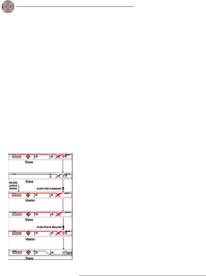
Figure 2.5. E-bus network with master units
Installation ~ Networking Units
Device IDs
Once your expansion bus connections are made (and if you have more than one XAP 400 at a site), you need to set up a unique expansion bus device ID number–a network address–for each XAP 400 on the network. As shipped from the factory, all XAP 400s default as device ID 0.
To assign device IDs
1.Press the front-panel Enter button, then scroll through the menu until the System menu is visible.
2.Press Enter, then scroll through the menu until Device ID is visible.
3.Press Enter, then scroll through the eight (0—7) options. When the desired Device ID is visible, press Enter to select it. (You can also set the Device ID in the Unit Properties window of G-Ware software see page 25.)
4.Repeat this process for each XAP 400 on the expansion bus network.
Mixer mode
There are two mixer mode settings: slave (default) and master. A master unit is not required in a networked system and in most installations, all units will be slaves. Master units ignore audio from upstream units. This prevents audio from being received from units above the master unit in the network. However, global control of the system is still maintained by whichever XAP 400/800 or PSR1212 unit is connected to a control device through its RS-232 or RS-485 ports. Control is not affected by master/slave designations.
In Figure 2.5, the third unit in the network is a master. It prevents the audio from the first and second units from being passed down the network chain. Likewise the second master unit in the network will not pass on the audio from the unit before it. The third unit provides system-wide control through a connection to its RS-232 port.
To select a mixer mode
1.Press the front panel Enter button and scroll through the menu until System menu is visible. Press Enter to select the menu.
2.Scroll through the System menu and select Mixer Mode.
3.Select the mixer setting you want to use. Repeat for additional units.
Technical Services Group ~ 1-800-283-5936 (USA) ~ 1-801-974-3760

Installation ~ LCD Programming
LCD Programming
The XAP 400’s front panel is intuitive to operate, thanks to its simple interface: a 2x16 character LCD, menu buttons, and a peak-level LED bar meter. Although most of the XAP 400’s features are programmed with G-Ware software (see page 23), the front panel can be used for simple adjustments and meter monitoring.
When power is applied to the XAP 400, the LCD panel will first read INITIALIZING. If an error is displayed, contact technical support. When initialization is complete, “XAP 400” is displayed on the top line and “Unit 0” is displayed on the bottom line.
LCD menu tree
The menu tree features fivemain menus, each with submenus. These branches typically end when an adjustable parameter or viewable value is reached. The diagram below shows the LCD menu tree.
13
|
G-Ware software is |
|
required to c |
omplete |
|
|
system setup. |
|
|
Pressing ESC at the top of |
the tree does nothing. |
Figure 2.6. LCD menu tree
Technical Services Group ~ 1-800-283-5936 (USA) ~ 1-801-974-3760

14 Installation ~ LCD Programming
The five main menus are: System, RS-232, Meter, Inputs, and Outputs. All submenu items are arranged under these menus. Use the Enter button to select items and the and buttons to scroll through menus and submenus. When the last menu item is reached, the display scrolls back to thebeginning of the list. The Esc button allows you to back out of the menus.
To adjust a parameter
1. Scroll to the parameter you want to adjust. Press Enter to select the parameter. The parameter will flash when selected.
2. Adjust the value with the and buttons. As the value is adjusted, the parameter is updated immediately.
3. To store the new value, press Enter. To discard the change and revert back to the old value, press Esc.
If the Meter button is pressed while a parameter is being adjusted, the LCD will switch to the Meter menu.
System menu
There are eight system-level parameters (see Figure 2.6): Select Preset, Run Macro, Lock Panel, Set Passcode, Device ID, Mixer Mode, Unit ID, and Firmware Version. The latter two are read only; they cannot be changed.
Select Preset
The Select Preset menu item allowsfor one of 32 preprogrammed presets to be selected for XAP 400 use. To select a preset, scroll through the numbered presets (1-32) until the desired preset is visible, then press Enter to run the preset.
Run Macro
The Run Macro menu item allows you to execute a macro. To select a macro, scroll through the numbered macros (1-255) until the desired macro is visible, then press Enter to run the macro.
Lock Panel
The front panel may be locked to prevent unauthorized adjustments to the XAP 400. To lock the front panel, use the / buttons to select Lock Panel fromthe System menu, and press Enter. Lock Panel selections are Off, On, or On at Timeout. Press Enter to enable your selection.
Technical Services Group ~ 1-800-283-5936 (USA) ~ 1-801-974-3760
Installation ~ LCD Programming
To unlock the front panel, attempt to adjust a parameter. The XAP 400 will prompt for the passcode. Upon entering the fifth character (if entered correctly), the front panel will unlock. The default passcode for all boxes is Enter.
Set Passcode
Once the XAP 400 is unlocked, the passcode may be changed. Before the XAP 400 will allow passcode changes, the new passcode must be entered, then re-entered to validate the new passcode.
The front panel passcode can also be set (and reset) within G-Ware. See page 26 for more information.
Device ID
The XAP 400’s device ID is set from this menu. There are eight device ID selections to choose from (0—7). Select the network position you want to use. Within a single site, you must assign different device ID numbers for each XAP 400 unit. See Device IDs, page 12.
Unit ID
The Unit ID menu selection allows you to access the read-only address set at the factory. This unique ID number identifies your particular XAP 400 unit and cannot be changed.
Mixer Mode
This setting allows you to set to master or slave mode. See page 12 for details.
Firmware Version
This menu selection allows you to view which firmware version is being used. This information cannot be changed.
RS-232 menu
There are four submenus under the RS-232 menu: Baud Rate, Flow Control, Enable Modem, and Clear Password.
Baud Rate
This parameter allows you to set the XAP 400’s baud rate to 9.6kbps,19.2kbps, 38.4kbps, or 57.6kbps. Default is 38.4kbps. Select the baud rate you want to use, then press Enter.
|
|
|
|
|
|
|
15 |
|
|
|
|
|
Menu items can |
sti ll be |
|
scrolled t hrough when the |
|||
|
panel is locked. However, |
||
settings cannot be entered un til the |
|||
panel is |
unl ocked with |
the |
|
appropriate passcode. |
|
|
|
Technical Services Group ~ 1-800-283-5936 (USA) ~ 1-801-974-3760

16
|
ClearOne recommends that |
you leav e Flow Control |
|
|
enabled. |
|
The |
modem initialization |
|
string can on ly b e set via |
|||
|
the |
MINIT |
serial |
command (se e p age 130) |
or the |
||
G-Ware softwa re. It cannot |
be set |
||
through the front panel LCD. |
|
||
|
You can s et the modem |
password using the |
|
|
MPASS serial comm and |
(see pa ge 13 1) o r i n G- Ware (see page 26).
Installation ~ LCD Programming
Flow Control (hardware)
The XAP 400 uses the RTS and CTS pins onthe RS-232 port to regulate the transmission and reception of data. You canenable or disable flow control on the front panel of unit and select the flow control type in the Site Properties window of G-Ware (see page23). If you select On (default) from the front panel menu, select Hardware as the flow control type in the Site Propertieswindow. If you disableflow control on the front panel, select None in the Site Properties window. When None is selected, the XAP 400 ignores flow control, making the connected external control device ensure that data is not lost. Software flow control (Xon/Xoff) is supported by the XAP/PSR units and is only used with a pass-through device, such as a modem.
To avoid communication errors, ClearOne strongly recommends that you connect all DB9 pins and enable flow control when connecting to a PC.
Enable Modem
This parameter configures the RS-232 port for connection of a modem. When On is selected, the XAP 400 will send an initializationstring to the modem on power-up and require a password before data transfer is allowed through the port. When Off (default) is selected, the password is disabled.
To use the XAP 400 with a modem
1.Match the baud rate of the modem to that of the XAP 400.
2.Turn off Serial Echo on the modem.
3.Turn off the modem’s response mode (e.g., no OK messages, ring, etc.).
4.Enable auto-answer on the modem.
Clear Password
This parameter allows you to erase the serial port (modem) password in case it has been forgotten. Select Yesto keep the current password or No to erase it. Press Enter to enable your selection.
Meter menu
There are 10 submenus under the Meter menu: Inputs, Outputs, Processing, ERL, ERLE, Telco RX, Telco TX, TERL, TERLE, and Default Meter. The meter selection determines what is shown on the front panel peak-level LED display. When the meter is selected in the LCD menu tree, the LCD displays peak level indications as well. Use the and buttons to select the Metermenu, then scroll through the options and press Enter when you reach the desired option.
Technical Services Group ~ 1-800-283-5936 (USA) ~ 1-801-974-3760

Installation ~ LCD Programming |
|
17 |
|
Inputs
Select which input (1—4) you want to monitor on the LCD and LED display. Scroll to the input, then press Enter. The meter displayed is the post-gain meter.
Outputs
This submenu allows you to choose which output (1—8) you want to monitor on the LCD and LED display. Scroll to the output you want to monitor, then press Enter.
Processing
This submenu allows you to choose which processing channel (A-D) you want to monitor on the LCD and LED display. Scroll to the output you want to monitor,then press Enter.
ERL
This submenu allows monitoring of the ERL meters on the XAP 400. Select the meter you want to monitor and press Enter.
ERLE
This submenu allows monitoring of the ERLE meters on the XAP 400. Select the meter you want to monitor and press Enter.
Telco RX
This submenu allows you to monitor the Telco RX (Receive) meteron the XAP 400. Press Enter to enable your selection.
Telco TX
This submenu allows you to monitor the Telco TX (Transmit) meter on the XAP 400. Press Enter to enable your selection.
TERL
This submenu allows you to monitor the TERL meter on the XAP 400. Press Enter to enable your selection.
Technical Services Group ~ 1-800-283-5936 (USA) ~ 1-801-974-3760

18 |
|
Installation ~ LCD Programming |
|
TERLE
This submenu allows you to monitor the TERLE meter on the XAP 400. Press Enter to enable your selection.
Default Meter
This submenu determines what is displayed on the LED meter when a meter is not specifically selected elsewhere in the Meter menu. The default is Output 8.
The Meter Reference Point diagram on following page shows where the meter pick-up points (  ) are in the signal path through the XAP 400.
Inputs menu
There are two submenus under the Inputs menu: Mute and Gain. To access these submenus you must first select the input. Choose from Inputs 1—8, Global, or From Telco. Use the and buttons to select the Inputs menu, then scroll through the options and press Enter when you reach the desired option.
Mute
This submenu allows you to turn mute on or off (default) for the selected input.
Gain
This submenu allows you to adjust the gain for the selected input. Use the and buttons to increase or decrease gain.
Outputs menu
There are two submenus under the Outputs menu: Mute and Gain. To access these submenus you must first select the output. Choose from Outputs 1—8, Speaker, or To Telco. Use the and buttons to select the Outputs menu, then scroll through the options and press Enter when you reach the desired option.
Mute
This submenu allows you to turn mute on or off (default) for the selected output.
Gain
This submenu allows you to adjust the gain for the selected output. Use the and buttons to increase or decrease gain.
Technical Services Group ~ 1-800-283-5936 (USA) ~ 1-801-974-3760

|
|
|
Installation ~ LCD programming |
|
19 |
|
||
|
|
|
Figure 2.7. Meter Reference Point diagram
Technical Services Group ~ 1-800-283-5936 (USA) ~ 1-801-974-3760

20
Technical Services Group ~ 1-800-283-5936 (USA) ~ 1-801-974-3760

CHAPTER 3: System
Configu rati on
ClearOne’s G-Ware software provides an easy interface for configuring and controlling your XAP 400. While some configuration can be done using the front panel LCD menus, G-Ware is required to complete the custom configuration of your audio conferencing system. If you are using the default settings, no configuration is necessary.
This chapter describes how to install G-Ware, create a site, and set up the telco portion of your system. It also describes all configurable parameters of your system. These descriptions are designed to be used as a guide as you make adjustments for your particular installation. It is not necessary to configure all parameters.
G-Ware Requirements
G-Ware software must operate on computer equipmentthat meets the following minimum requirements:
Windows 95 OSR2 |
64MB RAM |
Windows 98 |
64MB RAM |
Windows ME |
64MB RAM |
Windows NT |
64MB RAM |
Windows 2000 |
129MB RAM |
Windows XP |
256MB RAM |
PII 200MHz or AMD Equal
1024x768 SVGA (16bit) high color
8M Video card IE 4.0
20M HD space RS-232 COM port CD-ROM drive
Technical Services Group ~ 1-800-283-5936 (USA) ~ 1-801-974-3760

22
|
You ca n also a ccess the |
Disk Cop y program f rom |
the G-Ware insta ll me nu which is located on the AV Products CD (exefiles\gware\setup.exe).
System Configuration ~ Installing G-Ware
Creating floppy disk copies
Depending upon the computer equipment you have available,you might need to install G-Ware software fromfloppy disks rather than the included CD. To do this, a Disk Copy program is provided in G-Ware that allows you to transfer G-Ware to floppy disks. You will need a PC with a CD-ROM drive to make the transfer.After installing G-Ware on the CD-ROM-equipped computer, youcan access the Disk Copy program in the following way:
•From the Windows Start menu, select Programs, ClearOne G-Ware, and then Create Install Floppy Disks. Follow the onscreen prompts to complete creation of the floppy disks.
|
To s elect an alterna |
te |
destination directory, click |
||
Browse and use the Choose Directory window to find the desired location. Click OK to retu rn to the previous window.
Figure 3.1. Desktop icon
Installing G-Ware
To install G-Ware
1.Boot the PC to the Windows operating system. Ensure that all other programs or applications are closed. Insert the Audio and Video Products CD into the CD-ROM drive.
If the Autorun feature is enabled on the P C, the ClearOne Welcome window opens. Click the Software tab and select G-Ware.
If the Autorun window does not open, open the Windows Start menu and choose Run. Type “<drive>:\\gentner.exe” where <drive> is the letter of the CD-ROM drive (e.g., D:\\gentner.exe).
2.At the G-Ware window, click Install G-Ware near the bottom of the window.
3.The InstallShield Wizard opens, and guides you through the Welcome and License Agreement windows. At the Choose Destination Location window, choose the directory where G-Ware will be installed. We recommend that you use the default directory.
4.Click Next or Yes to move to proceed through the windows that follow or No or Cancel to end the installation process.
5.Follow the onscreen instructions. You must restart your computer once installation is complete.
The G-Ware Program Folderis now added to your Start menu. You can start G-Ware through the Start menu or by double-clicking the desktop icon.
Technical Services Group ~ 1-800-283-5936 (USA) ~ 1-801-974-3760

System Configuration ~ Site Setup
Site Setup Creating a new site
New site files are created through the Site Properties window in G-Ware. A site file contains all information about a particular installation including all unit settings and properties. It also provides G-Ware with the necessary information to communicate with the site hardware using your PC. Open G-Ware by double clicking the desktop icon or by selecting G-Ware from the Start menu.
To create a new site
1.Open the Site Properties window by selecting New Site from the File menu or by clicking the New Site button on the toolbar.
2.In the Site tab, enter the site name, author, company, location, room, and description, using the Tab key or mouse to select each field.
3.Click the Comm tab. Select the COM port, baud rate, and flow control you want to use. ClearOne recommends that you leave Flow Control set to Hardware. The Software setting is not supported by XAP/PSR units and is typically used with modems.
4.If you plan to use a modem, select Use Modem and enter the phone number, initialization string, and reset string.
5.Click the Security tab. Enter the site password in the Site Password box. Click File Access Password to create a password for the Site File.
Figure 3.3. Site Properties, Site tab |
Figure 3.4. Site Properties, Comm tab |
Technical Services Group ~ 1-800-283-5936 (USA) ~ 1-801-974-3760
23
|
Whenever a mouse click is |
indicated in this manual, it |
refers to the left mouse button unless otherwise stated.
Figure 3.2.
New Site button
|
You can e nable flow |
control using the XAP |
page 16. front pa nel co ntrols. See
Figure 3.5. Site Properties, Security tab

24
Figure 3.6. Open
Site File button
Figure 3.7.
Connect button
Figure 3.9. Add Unit
to Current Site
System Configuration ~ Site Setup
Adding a XAP 400
You can add a XAP 400(s) to your site file by connecting to your site and using G-Ware to automatically create icons for the detected units. Or, you can work offline and manually add the unit(s) to the site file and connect to the site at a later time. To open an existing site file, click the Open Site File button or select Open Site from the File menu.
To auto-detect units
1.Click the Connect button on the G-Ware toolbar or select Connect from the Connect Menu.
2.Choose Sync to Unit(s). G-Ware will automatically create icons for the new units it detects on the network and place them in the Site pane. See Figure 3.11.
Figure 3.8. Connection choices
Note: When connecting to your site, you can choose to sync to Unit(s) or Document. If you sync to the Unit(s), you will overwrite your G-Ware site file with the current settings of the unit(s). If you sync to the Document, you will overwrite the settings in your units with the settings you have saved in the site file. Choosing to sync to Document will also create icons for any new units.
To manually add units
1.If you are working offline, click the Add button on the G-Ware toolbar. This opens the Add Unit window.
Figure 3.10. Add Unit window
2. Select the XAP 400 icon and click Add.
Technical Services Group ~ 1-800-283-5936 (USA) ~ 1-801-974-3760
Loading...