

Page 1
Titan™ Media Cart
InstallatIon and operatIon Manual
Page 2

tAble of contents
INTRODUCTION
SERVICE AND SUPPORT ......................................................................................... 1
PRODUCT RETURNS ............................................................................................... 1
UNPACKING .............................................................................................................. 1
TITAN SINGLE MEDIA CART .................................................................................... 2
TITAN DUAL MEDIA CART ........................................................................................ 2
BEFORE YOU BEGIN ................................................................................................ 3
ASSEMBLY
TITAN SINGLE MEDIA CART .................................................................................... 4
Assembling the hArdwAre ......................................................................4
mounting the screen..............................................................................6
TITAN DUAL MEDIA CART ........................................................................................ 7
Assembling the hArdwAre ......................................................................7
mounting the screens ...........................................................................9
ATTACHING A PTZ CAMERA.................................................................................. 10
ATTACHING THE CODEC SHELF .......................................................................... 11
APPENDIX
SPECIFICATIONS ................................................................................................... 12
TITAN MEDIA CART INSTALLATION AND OPERATION MANUAL
CLEARONE PART NO. 800-300-101 JANUARY 2012 (REV. 4.1)
© 2012 ClearOne Communications, Inc. All rights reserved. No part of this document
may be reproduced in any form or by any means without written permission from
ClearOne Communications. Printed in the United States of America. ClearOne
reserves specific privileges. Information in this document is subject to change
without notice
Page 3

Introduction
The Titan™ Media Carts provide superior strength, mobility and storage
space. They are a perfect blend of heavy duty construction and professional
styling. Our durable metal carts are an attractive, highly functional addition
to any conferencing environment. The ability to hold one screen (single cart)
or two screens (dual cart) makes Titan perfect for large conference rooms
or distance learning facilities. See the Specifications section on page 12 for
maximum screen sizes.
service And support
If you need additional information on how to install, set up or operate your
Titan Media Cart, please contact us. We welcome your comments so that we
can continue to improve our products and better meet your needs.
Support
Tel: 1.800.283.5936
1.801.974.3760
Fax: 1.801.974.3669
Email: tech.support@clearone.com
product returns
All product returns require a return materials authorization (RMA) number.
Please contact ClearOne Technical Support before attempting to return your
product. Make sure you return all the items that shipped with your product.
unpAcking
Carefully remove all items that ship with the Titan Media Cart. Ensure you
have received all items shown on the following page. If you are missing any
items, please contact our Service Department at 1-800-283-5936.
NOTE: ClearOne is not responsible for product damage incurred
during shipment. You must make claims directly with the carrier.
Inspect your shipment carefully for obvious signs of damage. If
the shipment appears damaged, retain the original boxes and
packing material for inspection by the carrier. Contact your carrier
immediately.
Introduction 1
Page 4
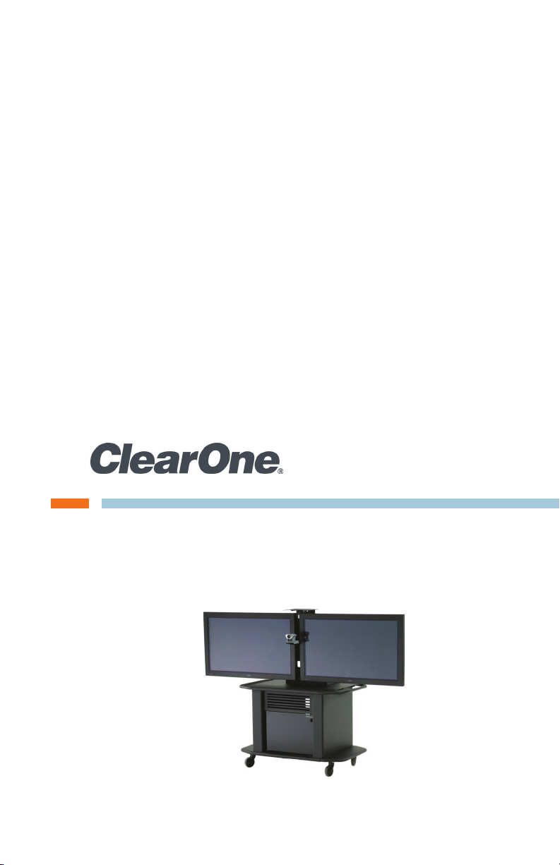
titAn single mediA cArt
Manual
8-32 Pan Head Screws
Qty: 2
5/16 Nuts
Qty: 12
Vertical Support
Universal Base with Support Top
SHE
Codec Shelf 1/4-20 Screw
Qty: 1
5/16 Bolts
Qty: 20
5/16 Washers
Qty: 12
NOTE: Depending on your options, not all included hardware will
be used when assembling the Titan Single Media Cart.
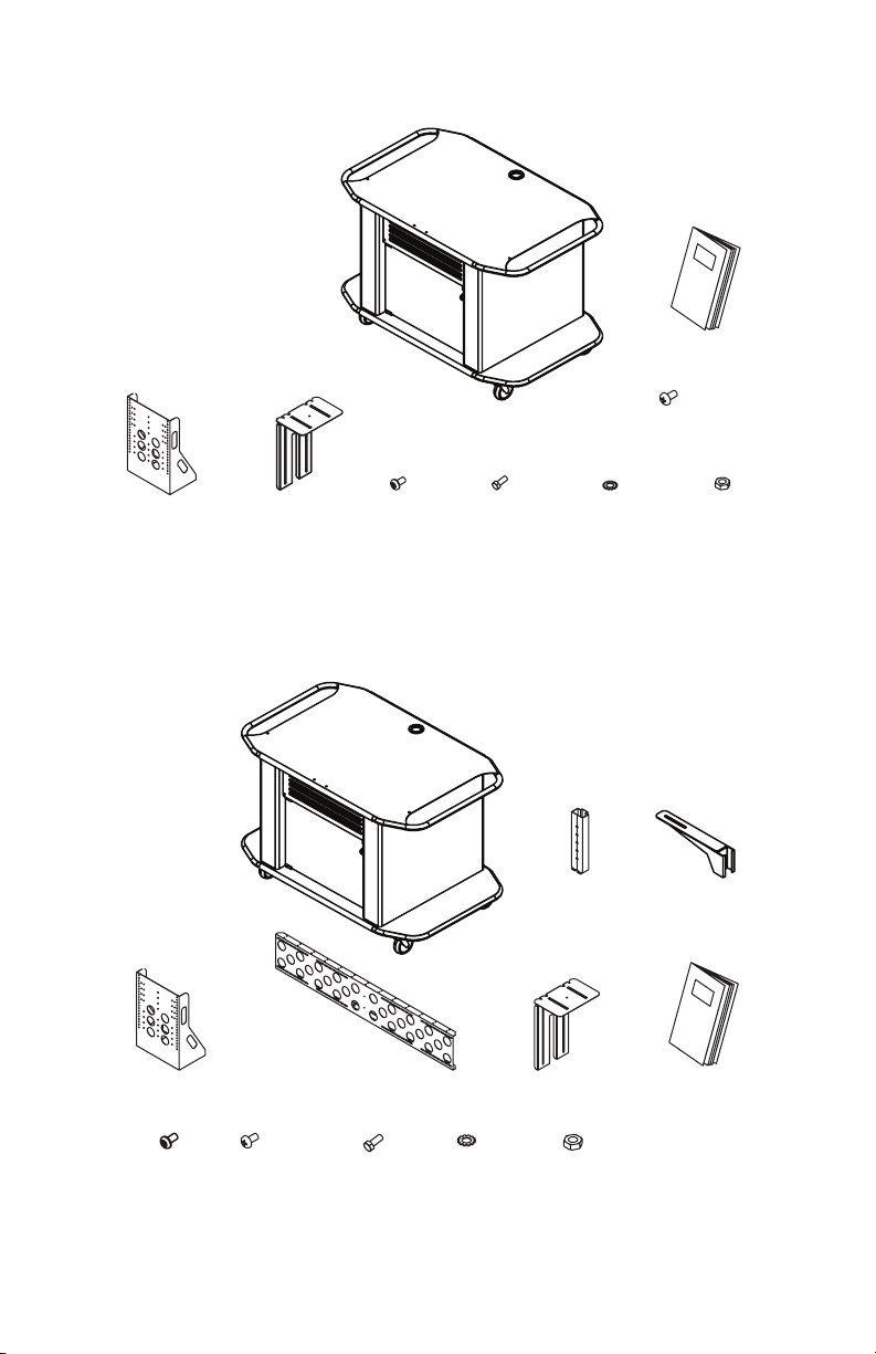
titAn duAl mediA cArt
Universal Base with Support Top
Rail Track
Bracket
Vertical SupportHorizontal SupportCodec Shelf
1/4-20 Screw
Qty: 1
8-32 Pan Head Screw
Qty: 2
5/16 Bolts
Qty: 20
2 Technical Support: 800.283.5936
5/16 Washers
Qty: 12
5/16 Nuts
Qty: 12
Manual
Page 5

before You begin
Before you begin assembling your Titan Media Cart, be sure to have the
following:
• OmniMount 1N1-L screen mount (single screen configuration)
or
OmniMount VB150F (X2) screen mounts (dual screen configuration)
• 1/2” wrench
• Socket wrench with 1/2” socket
• Phillips screw driver
The Titan Media Carts require one mount for each screen that is to be
secured to the unit. Both the OmniMount 1N1-L and the OmniMount VB150F
include a wall mount that connects to the cart and vertical rails that attach
to the back of the monitor. The OmniMount 1N1-L and VB150F are not sold
by ClearOne and are not included with the Titan Cart systems, but must be
purchased separately. Contact the Service Department at 1-800-283-5936
for more information.
Introduction 3
Page 6

Assembly
titAn single mediA cArt
ASSEMBLING THE HARDWARE
1. Align the Vertical Support over the self-clinching nuts in the Universal
Base.
» NOTE: The self-clinching nuts are attached to the top of the
Universal Base.
2. Secure the Vertical Support using six 5/16 Bolts.
Bolts
Vertical Support
Support Top
Universal Base
4 Technical Support: 800.283.5936
Page 7

3. Remove and set aside the Locking Bar from the OmniMount 1N1-L Flat
Panel Mount assembly (not supplied), then securely anchor the mount
to the Vertical Support using four 5/16 Bolts, four 5/16 Washers and
four 5/16 Nuts.
NOTE: The Flat Panel Mount can be attached higher or lower on
the Vertical Support depending on desired position and size of
screen.
Locking Bar
and Screws
Wall Plate
Washers and Nuts
Bolts
4. Using hardware supplied with the 1N1-L mount, attach the vertical rails to
the back of the screen. (See 1N1-L instructions for more information.)
Vertical
Rail
Screen
Assembly 5
Page 8

MOUNTING THE SCREEN
1. With the aid of another person, lift the screen up to the Flat Panel
Mount and align the tabs on the Vertical Rails with the top and bottom
horizontal bars of the Flat Panel Wall Mount that is mounted on the
vertical support.
Vertical Rails
Locking Bar
and Screws
Over Wall Mount
Flat Screen
Display
2. Slide the screen down into place.
3. Place and secure the Locking Bar with the included screws over the
top horizontal bar of the mount, locking the Vertical Rails to the wall
mount.
» NOTE: For instructions on installing the Codec Shelf, see page
11.
6 Technical Support: 800.283.5936
Page 9

titAn duAl mediA cArt
ASSEMBLING THE HARDWARE
1. Align the Vertical Support over the self-clinching nuts in the Universal
Base.
» NOTE: The self-clinching nuts are attached to the top of the
Universal Base.
Universal Base
2. Secure Vertical Support using six 5/16 Bolts.
3. Line up the Horizontal Support alignment pins with the guiding holes
on the Vertical Support at desired height and slide into place.
4. Hold the Horizontal Support in place while securing it to the Vertical
Support using six 5/16 Bolts.
Bolts
Vertical Support
Support Top
» NOTE: The Horizontal Support can be raised or lowered on the
Vertical Support to achieve the desired viewing position of the
screens.
Horizontal Support
Alignment
Pin
Bolts
Assembly 7
Page 10

5. Attach the Rail Track to the Horizontal Support using two 8-32 Pan
Head Screws.
6. Slide the Camera Bracket down over rail.
» NOTE: Attaching the Camera Bracket is optional. The bracket is
normally used with codecs that have a detachable camera or with
a small PTZ camera. This bracket allows the camera to be placed
at eye-level between the monitors.
Camera Shelf
Pan Head Screws
Rail Track
Horizontal Support
» NOTE: To adjust the Camera Shelf height, pull the Adjusting Pin out
of the Rail Track, slide the Camera Bracket to the desired height,
and replace the Adjusting Pin.
7. Securely anchor the Wall Plates (not supplied) to the Horizontal
Support using eight 5/16 Bolts, eight 5/16 Washers and eight 5/16
Nuts.
Washers and Nuts
Horizontal
Support
Washers and Nuts
Wall Plate
Bolts
» NOTE: Adjust the position of the Wall Plates based on the size of
the screens.
8 Technical Support: 800.283.5936
Bolts
Page 11

8. Using hardware supplied with the Wall Mount, attach the Vertical Rails
with the Rubber Stops to the back of the screen. (See OmniMount
VB150F instructions for more information.)
» NOTE: Titan Media Carts require one OmniMount VB150F Wall
Mount (not supplied) for each screen that is to be secured to the
support.
Rubber Stop
Vertical
Rails
Rubber Stop
MOUNTING THE SCREENS
1. With the aid of another person, lift the screen up to the Wall Plate
attached to the Horizontal Support and align the tabs on the Vertical
Rails above the Wall Plate.
WARNING: Due to a potential tipping hazard, the cart should not be
moved until both screens are securely mounted.
Horizontal Support
Wall Plate
Locking Bar
Vertical Rail
Assembly 9
Page 12

2. Lower the screen into place with the Vertical Rails hooking over the
Wall Plate.
3. Thread the Locking Bar from the side through the Wall Plate and both
Vertical Rails. When fully inserted, turn in place to position locking tab..
NOTE: For instructions on installing the Codec Shelf, please see
page 11.
AttAching A ptZ cAmerA
1. Secure the camera to Camera Bracket using the 1/4-20 Screw.
Camera
Camera
Bracket
» NOTE: Different camera models can be attached to the Camera
Bracket using individual mounting hardware supplied by the
camera manufacturer.
10 Technical Support: 800.283.5936
Page 13

AttAching the codec shelf
NOTE: The Codec Shelf supports a set-top codec or PTZ camera;
using the shelf is optional.
1. Align the Codec Shelf with the guiding holes on the Vertical Support.
Codec Shelf
Washer
and Nut
(Screen Mounting Hardware Not Shown.)
Support Top
2. Secure the Codec Shelf to Vertical Support using the attached bolts on
Vertical Support, four 5/16 Washers, and four 5/16 Nuts.
» NOTE: The Codec Shelf can be positioned on the Vertical Support
to accommodate various sizes and styles of screens.
Assembly 11
Page 14

Appendix
specificAtions
Dimensions (W x H x D)
45” x 31” x 28”
Assembled Dimensions without screens (W x H x D)
Single: 45” x 72” x 28”
Dual: 72” x 72” x 28”
Integrated Rack
Height: 9 space, 15.75” (40 cm)
Depth: 22”
Rack rails: included
Rail recess: 2” clearance from door
Casters
Heavy duty (250 lb. rating each)
6 1/2” clearance with 5” diameter
Caster Composition
Precision synthetic, plate-mounted, double ball bearing, with swivel
head and polypropylene tread
Vented Back Panel
Height: 17”
Width: 17”
Attachment: Four #8-32 screws
Weight Capacity
800 lb (364 kg)
Construction
14-, 12-, and 11-gauge steel
Columnar support, channel welded
Screen Support
Single: One screen (maximum size 65”, 39 1/2“ max height)
Dual: Two screens (maximum size 56”, 51 1/2 max width ea.)
Part Numbers
911-300-101 Titan Single Media Cart
911-300-110 Titan Dual Media Cart
12 Technical Support: 800.283.5936
Page 15

Appendix 13
 Loading...