

Page 1
Titan Articulating Arm Dual Media Cart
INSTALLATION INSTRUCTIONS
Page 1
Page 2
INSTRUCTIONS
4 each (per TV) [8 each]
4 each (per TV) [8 each]
4 (per TV) [8] 5 (per TV) [10]
4 (per TV) [8]
1
Used to secure camera to shelf
Not shown in any assembly images
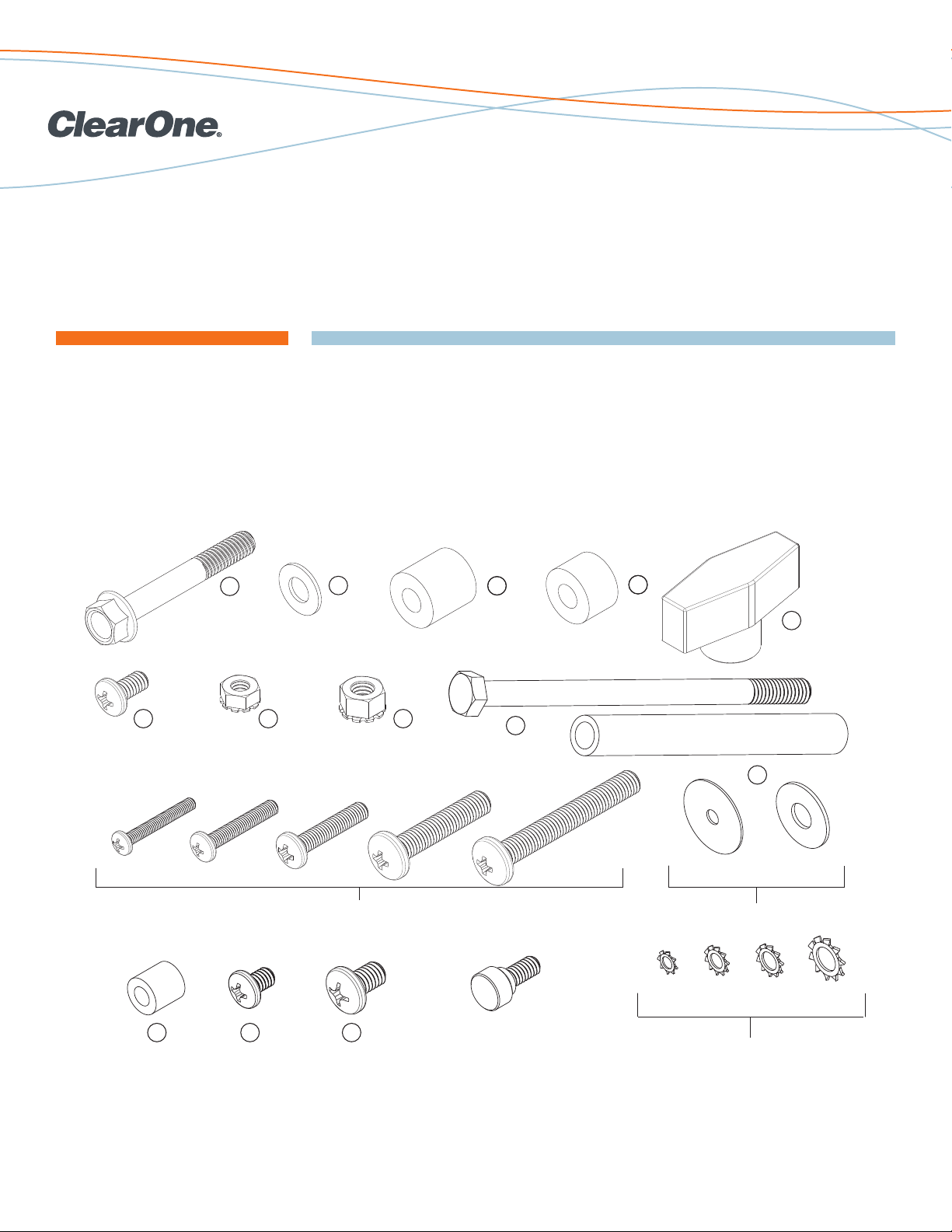
8X
A
8X
B
16X
C
D
2X
2X
E
F
4X
G
5X 1X
H
1X
I
1X
J
4 each (per TV) [8 each]
M4 M5 M6 M8 M8
Use with
M4 or M5
Use with
M6 or M8
Use with
M6
Use with
M8
Use withM4Use with
M5
K
L
M
CLEARONE DOCUMENT 800-300-025-01
(REVISION 2.0) February 2013.
TITAN DUAL ARTICULATING ARM MEDIA CART
The Titan Dual Articulating Arm Media Cart is assembled from the shipped parts using standard tools.
PARTS USED IN ASSEMBLY
Page 2
Page 3
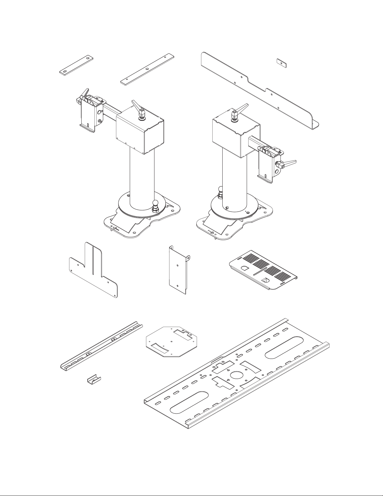
MEDIA CART COMPONENTS USED IN ASSEMBLY
Short Plate
4X
Left Side Assembly
1X
Long Plate
4X
Lock Plate
2X
Spacer Bracket
1X
Right Side Assembly
1X
TV Bracket
2 (per TV) [4]
TV Inner Bracket
4 (per TV) [8]
Adjustable Channel Tilt Camera ShelfCamera Mounting Bracket
Reinforcing Plate
1 (per TV) [2]
TV Mounting Tray
1 (per TV) [2]
Page 3
Page 4

INSTRUCTIONS FOR ASSEMBLING THE
ARTICULATING ARMS AND TV’S ON THE MEDIA CART
Step 1
1. Place the Right Side Assembly on the top of the cart. Note that the directional arrows at the base of the assembly are to
indicate the right or left assembly and point to the outside of the cart when positioned.
2. Align the holes of the assembly to the corresponding holes on the top of the cart.
Right Side Assembly
A
B
C
Long Plates
Short
Plates
C
Page 4
Page 5

Step 2
1. Bolt the Right Side Assembly on the top of the cabinet using 4 bolts (A), 4 washers (B), 2 Short Plates and 2 Long plates
with the 4 spacers (C) provided to fill the gap between the long and short plates. Be sure to put Long plates and spacers
(C) outside and inside the cabinet. The Long Plates are threaded to accept the bolts. Do not overtighten the bolts.
C
Short Plates
Step 3
1. Repeat the procedure for the Left Side Assembly.
A
Long Plate
Page 5
Page 6

Step 4
1. Assemble the Camera Mounting kit by attaching the Camera Mounting Bracket to the Spacer Bracket with 4 bolts (F) and
lock nuts (G).
2. Attach the Adjustable Channel to the Camera Mounting Bracket. The Adjustable Channel has an embedded bolt that can
be fastened with a nut (G) on the opposite side.
3. Attach the Tilt Camera Shelf to the Adjustable Channel using the bolt (I), spacer (J) and nut (H).
Tilt Camera Shelf
J
H
Adjustable Channel
I
Camera Mounting Bracket
G
Step 5
1. Remove the Clamping Lever from the top of each Articulating Arm assembly.
2. Place the Spacer Bracket with the Adjustable Channel and Tilt Camera Shelf onto the threaded inserts and adjust
Articulating arms as needed.
3. Bolt it together using the Clamping Levers and provided flat washers.
4. Make sure the Articulating Arms are securely tightened to the cabinet.
F
Spacer Bracket
Page 6
Page 7

Step 6
1. Assemble the mounting for each TV display. Place the TV’s face down on a safe, non-scratch solid surface. Use the TV
Brackets, Inner Brackets, Spacers, M4, M5, M6 or M8 screws, lock washers and washers suitable to the mounting holes
of the TV. Position the TV Inner Brackets inside the TV Brackets, adjust to the proper spacing for your mounting holes, then
place screws, washers and optional spacers so that the assemblies are firmly in place. Do not overtighten the screws or
use power tools for assembly.
Optional
K
Spacers
TV Inner Bracket
Reinforcing Plate
TV Bracket
2 (per TV) [4]
M
TV Mounting Tray
2. Mount the Reinforcing Plate on the TV Tray, then the TV Tray with Reinforcing Plate to the TV Brackets. Slots in the TV
brackets and TV mounting tray may be used to adjust the vertical and horizontal position of the TV’s, respectively.
Depending on the size of the TV’s, this might be necessary to clear the top of the cart or to adjust the gap between the
units. Do not overtighten the screws or use power tools for assembly.
L
Page 7
Page 8
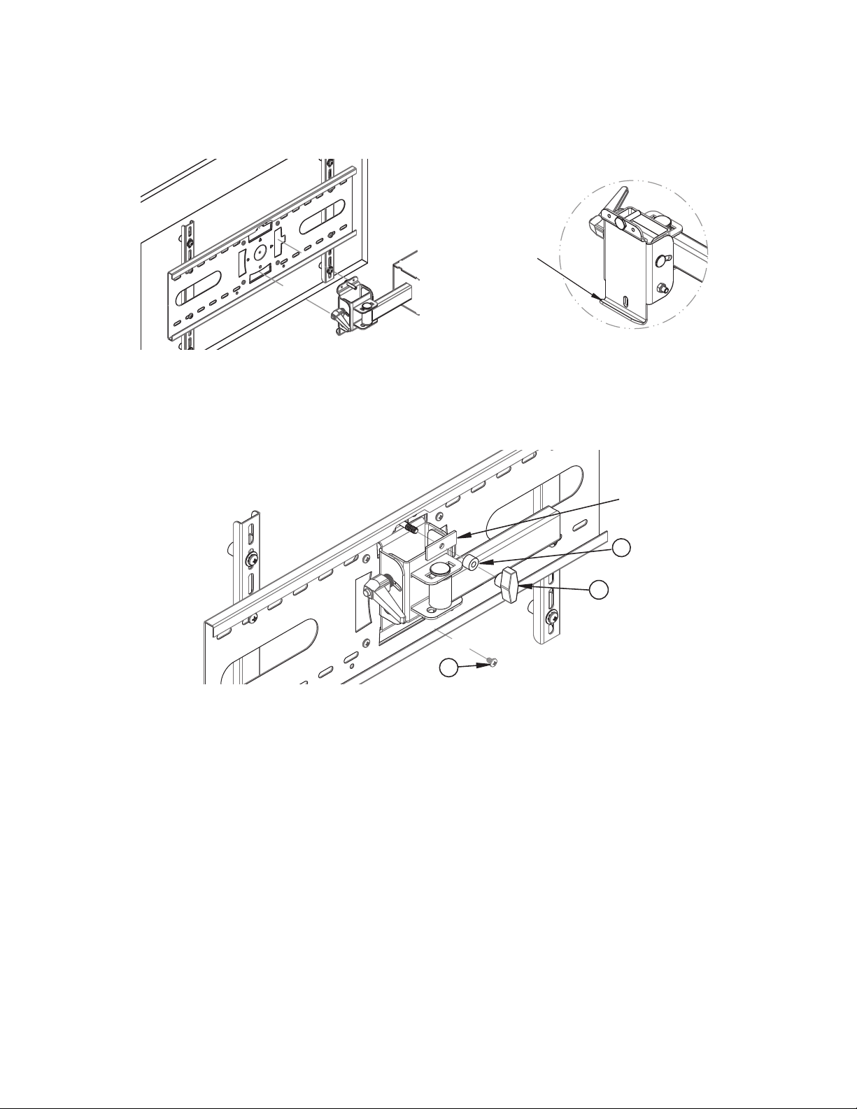
Step 7
1. Fully extend the arms to a position that allows for easy installation of the TVs. Lift the TV (with the attached mounting
hardware from step 6) onto the Articulating Arm. Make sure the Reinforcing Plate fits snug against the Articulating Arm
assembly with the weight supported by the TV Support Cleat on the articulating arm.
TV Support Cleat
NOTE: This operation requires the assistance of another person to lift and hold the TV into place as the
attachments are made.
2. Secure the TV to the Articulating Arm with the screw (L) placed through the hole near the bottom of the TV Support Cleat.
Then place the lock plate, spacer (D), and the lock knob (E) over the bolt at the top of the cleat on the articulating Arm,
then tighten. Note that there is a small amount of left-right tilt that can be brought level and set with the locking knob.
L
3. Repeat this procedure for the remaining TV and Articulating Arm.
Lock
Plate
D
E
Page 8
Page 9

Step 8
1. Power and equipment cables for the TV’s can be dressed through the Cable Access Holes in the Cabinet top, up through
the Spacer Bracket and over to the TV Mounting Plate to conceal them and make rotation of the Articulating Arms free from
obstruction.
Rear View of Completed Assembly
(TV’s not Shown)
TV Cable Access Holes
CLEARONE LOCATIONS
HEADQUARTERS:
Salt Lake City, UT USA
5225 Wiley Post Way
Suite 500
Salt Lake City, UT 84116
Tel: 801.975.7200
Toll Free: 800.945.7730
Fax: 801.977.0087
e-mail: sales@clearone.com
800-300-025-01 Rev. 2.0 © 2013 ClearOne, Inc. All rights reserved. Information in this document is subject to change without notice.
EMEA
Tel: 44 (0) 1189.036.053
e-mail: global@clearone.com
APAC
Tel: 852.3590.4526
e-mail: global@clearone.com
Page 9
LATAM
Tel: 801.974.3621
e-mail: global@clearone.com
TechSales
Tel: 800.705.2103
e-mail: techsales@clearone.com
Technical Support
Tel: 800.283.5936
e-mail: tech.support@clearone.com
 Loading...