

Page 1

CLEAR-COM ENCORE
RCS-2700 PROGRAMMABLE SOURCE ASSIGNMENT PANEL
INSTRUCTION MANUAL
Page 2

RCS-2700 Programmable Assignment Panel Instruction Manual
© 2007 Vitec Group Communications Ltd. All rights reserved.
Part Number 810500Z Rev. 1
Vitec Group Communications, LLC.
850 Marina Village Parkway
Alameda, CA 94501
U.S.A
Vitec Group Communications
7400 Beach Drive
Cambridge Research Park
Cambridgeshire
United Kingdom
CB25 9TP
Vitec Group Communications
Room 1806, Hua Bin Building
No. 8 Yong An Dong Li
Jian Guo Men Wai Ave
Chao Yang District
Beijing, P.R. China 100022
® Clear-Com, CellCom/FreeSpeak and the Clear-Com Communication Systems logo are registered trademarks of The Vitec Group
plc.
Page 3

CONTENTS
OPERATION . . . . . . . . . . . . . . . . . . . . . . . . . . . . . . . . . . . . . . . 1-1
Description . . . . . . . . . . . . . . . . . . . . . . . . . . . . . . . . . . . . . . . . . . . . . . . . . . 1-1
Overview . . . . . . . . . . . . . . . . . . . . . . . . . . . . . . . . . . . . . . . . . . . . . . . . . . 1-1
Remote-Controlled Operation. . . . . . . . . . . . . . . . . . . . . . . . . . . . . . . . . . 1-1
Typical Applications . . . . . . . . . . . . . . . . . . . . . . . . . . . . . . . . . . . . . . . . . 1-2
Connecting Multiple RCS-2700 Units . . . . . . . . . . . . . . . . . . . . . . . . . . . . . 1-2
ISO Channels and Groups. . . . . . . . . . . . . . . . . . . . . . . . . . . . . . . . . . . . . . . 1-3
Powering the System . . . . . . . . . . . . . . . . . . . . . . . . . . . . . . . . . . . . . . . . . . . 1-5
Powering a Single RCS-2700 Unit. . . . . . . . . . . . . . . . . . . . . . . . . . . . . . . 1-5
Powering Multiple RCS-2700 Units . . . . . . . . . . . . . . . . . . . . . . . . . . . . . 1-5
Front Panel . . . . . . . . . . . . . . . . . . . . . . . . . . . . . . . . . . . . . . . . . . . . . . . . . . 1-6
Lights . . . . . . . . . . . . . . . . . . . . . . . . . . . . . . . . . . . . . . . . . . . . . . . . . . . . 1-6
Power Light (1) . . . . . . . . . . . . . . . . . . . . . . . . . . . . . . . . . . . . . . . . . . . 1-6
Data Light (2) . . . . . . . . . . . . . . . . . . . . . . . . . . . . . . . . . . . . . . . . . . . . 1-6
System Expansion (“Sys Exp”) Light (3) . . . . . . . . . . . . . . . . . . . . . . . . 1-6
Fault Light (4) . . . . . . . . . . . . . . . . . . . . . . . . . . . . . . . . . . . . . . . . . . . . 1-6
Locked Light (5) . . . . . . . . . . . . . . . . . . . . . . . . . . . . . . . . . . . . . . . . . . 1-6
Preset Button (6) . . . . . . . . . . . . . . . . . . . . . . . . . . . . . . . . . . . . . . . . . . . . 1-7
Preset Configurations (“Presets”) . . . . . . . . . . . . . . . . . . . . . . . . . . . . . . 1-7
Selecting Presets from the Front Panel of the RCS-2700 . . . . . . . . . . . . 1-8
Code and Lock/Unlock Buttons (7 & 8) . . . . . . . . . . . . . . . . . . . . . . . . . . 1-8
Changing the Unlock Code. . . . . . . . . . . . . . . . . . . . . . . . . . . . . . . . . . 1-8
Locking the RCS-2700 . . . . . . . . . . . . . . . . . . . . . . . . . . . . . . . . . . . . . 1-9
Unlocking the RCS-2700 . . . . . . . . . . . . . . . . . . . . . . . . . . . . . . . . . . . 1-9
Remote RCU-67 Front-Panel Jack (9) . . . . . . . . . . . . . . . . . . . . . . . . . . . 1-10
Rear Panel . . . . . . . . . . . . . . . . . . . . . . . . . . . . . . . . . . . . . . . . . . . . . . . . . . 1-10
Address Switch (1). . . . . . . . . . . . . . . . . . . . . . . . . . . . . . . . . . . . . . . . . . 1-10
Code-Reset Button (2). . . . . . . . . . . . . . . . . . . . . . . . . . . . . . . . . . . . . . . 1-11
Remote RCU-67 Rear-Panel Jack (3). . . . . . . . . . . . . . . . . . . . . . . . . . . . 1-11
PC Serial Port (4) . . . . . . . . . . . . . . . . . . . . . . . . . . . . . . . . . . . . . . . . . . 1-11
Preset-Select Contact Closure (5). . . . . . . . . . . . . . . . . . . . . . . . . . . . . . . 1-12
Termination Switches (6). . . . . . . . . . . . . . . . . . . . . . . . . . . . . . . . . . . . . 1-12
INSTALLATION. . . . . . . . . . . . . . . . . . . . . . . . . . . . . . . . . . . . . . 2-1
Unpacking the RCS-2700 . . . . . . . . . . . . . . . . . . . . . . . . . . . . . . . . . . . . . . . 2-1
Wiring Overview. . . . . . . . . . . . . . . . . . . . . . . . . . . . . . . . . . . . . . . . . . . . . . 2-1
Source Connections (1) . . . . . . . . . . . . . . . . . . . . . . . . . . . . . . . . . . . . . . . 2-2
Power Patch Panel Connections (2) . . . . . . . . . . . . . . . . . . . . . . . . . . . . . . 2-2
Destination Connections (3) . . . . . . . . . . . . . . . . . . . . . . . . . . . . . . . . . . . 2-2
Source Expansion Connections (4) . . . . . . . . . . . . . . . . . . . . . . . . . . . . . . 2-2
Powering the RCS-2700 and Destinations. . . . . . . . . . . . . . . . . . . . . . . . . . . 2-2
Powering from Party-Line Sources . . . . . . . . . . . . . . . . . . . . . . . . . . . . . . . 2-2
RCS-2700 SOURCE ASSIGNMENT PANEL
i
Page 4

Powering from Multiple Party-Line Source Channels . . . . . . . . . . . . . . 2-3
Powering from One Party-Line Source Channel . . . . . . . . . . . . . . . . . . 2-3
Powering from a Separate Power Supply . . . . . . . . . . . . . . . . . . . . . . . . 2-4
Powering from TW Party-Line Sources . . . . . . . . . . . . . . . . . . . . . . . . . . . 2-5
Powering the RCS-2700 from a Separate Power Supply . . . . . . . . . . . . . . . 2-6
Connecting and Setting Rear Panel Controls . . . . . . . . . . . . . . . . . . . . . . . . . 2-7
Setting the Address Switch (1) . . . . . . . . . . . . . . . . . . . . . . . . . . . . . . . . . . 2-7
Setting the Address Switch for a Single-Unit System . . . . . . . . . . . . . . . 2-7
Setting Address Switches in a Multi-Unit System . . . . . . . . . . . . . . . . . 2-7
Using the Code-Reset Button (2). . . . . . . . . . . . . . . . . . . . . . . . . . . . . . . . 2-8
Connecting a Remote RCU-67 (3) . . . . . . . . . . . . . . . . . . . . . . . . . . . . . . 2-9
Connecting a PC (4) . . . . . . . . . . . . . . . . . . . . . . . . . . . . . . . . . . . . . . . . . 2-9
Wiring the Data-Links Connectors to Expansion Units (5) . . . . . . . . . . . 2-10
Wiring the Preset-Select Contact Closure (6). . . . . . . . . . . . . . . . . . . . . . 2-12
Setting Termination Switches (7). . . . . . . . . . . . . . . . . . . . . . . . . . . . . . . 2-12
Wiring Source Channels . . . . . . . . . . . . . . . . . . . . . . . . . . . . . . . . . . . . . . . 2-13
Basic Switching Theory . . . . . . . . . . . . . . . . . . . . . . . . . . . . . . . . . . . . . . 2-13
Wiring Source Channels in an 8-Source System. . . . . . . . . . . . . . . . . . . . 2-15
Wiring Source Channels . . . . . . . . . . . . . . . . . . . . . . . . . . . . . . . . . . . 2-15
Wiring Source-8 Connection Points . . . . . . . . . . . . . . . . . . . . . . . . . . 2-15
Wiring Source Channels in a 15-Source System. . . . . . . . . . . . . . . . . . . . 2-16
Wiring Source-8 Connection Points to Expansion Unit 1 . . . . . . . . . . 2-16
Wiring Source Channels in a 48- or 72-Destination System . . . . . . . . . . 2-16
Wiring Source-8 Connection Points to Expansion Units. . . . . . . . . . . 2-16
Wiring Destinations . . . . . . . . . . . . . . . . . . . . . . . . . . . . . . . . . . . . . . . . . . 2-19
Wiring Summary for 8-Source Systems . . . . . . . . . . . . . . . . . . . . . . . . . . . . 2-21
Wiring Summary for 15-Source Systems . . . . . . . . . . . . . . . . . . . . . . . . . . . 2-22
MAINTENANCE . . . . . . . . . . . . . . . . . . . . . . . . . . . . . . . . . . . . . 3-1
Troubleshooting Tips. . . . . . . . . . . . . . . . . . . . . . . . . . . . . . . . . . . . . . . . . . . 3-1
Block Diagram . . . . . . . . . . . . . . . . . . . . . . . . . . . . . . . . . . . . . . . . . . . . . . . 3-2
GLOSSARY . . . . . . . . . . . . . . . . . . . . . . . . . . . . . . . . . . . . . . . . 4-1
SPECIFICATIONS. . . . . . . . . . . . . . . . . . . . . . . . . . . . . . . . . . . . . 5-1
RCS-2700 Programmable Source Assignment Panel . . . . . . . . . . . . . . . . . . . 5-1
RCS-2700 System . . . . . . . . . . . . . . . . . . . . . . . . . . . . . . . . . . . . . . . . . . . . . 5-3
LIMITED WARRANTY . . . . . . . . . . . . . . . . . . . . . . . . . . . . . . . . . . .6-I
Warranty Period. . . . . . . . . . . . . . . . . . . . . . . . . . . . . . . . . . . . . . . . . . . . . . . 6-i
Technical Support . . . . . . . . . . . . . . . . . . . . . . . . . . . . . . . . . . . . . . . . . . . . . 6-i
Warranty Repairs and Returns. . . . . . . . . . . . . . . . . . . . . . . . . . . . . . . . . . . . 6-ii
Non-Warranty Repairs and Returns. . . . . . . . . . . . . . . . . . . . . . . . . . . . . . . . 6-ii
Extended Warranty . . . . . . . . . . . . . . . . . . . . . . . . . . . . . . . . . . . . . . . . . . . . 6-ii
Service Contract . . . . . . . . . . . . . . . . . . . . . . . . . . . . . . . . . . . . . . . . . . . . . 6-iii
ii
RCS-2700 SOURCE ASSIGNMENT PANEL
Page 5

Liability. . . . . . . . . . . . . . . . . . . . . . . . . . . . . . . . . . . . . . . . . . . . . . . . . . . . 6-iii
RCS-2700 SOURCE ASSIGNMENT PANEL
iii
Page 6

iv
RCS-2700 SOURCE ASSIGNMENT PANEL
Page 7

Please read and follow these
instructions before operating
this product.
IMPORTANT SAFETY INSTRUCTIONS
1. Read these instructions.
2. Keep these instructions.
3. Heed all warnings.
4. Follow all instructions.
5. Do not use this apparatus near water.
6. Clean only with dry cloth.
7. Do not block any ventilation openings. Install in accordance with the
manufacturer’s instructions.
8. Do not install near any heat sources such as radiators, heat registers, stoves,
or other apparatus (including amplifiers) that produce heat.
9. Only use attachments/accessories specified by the manufacturer.
10. Use only with the cart, stand, tripod, bracket, or table specified by the
manufacturer, or sold with the apparatus. When a cart is used, use caution
when moving the cart/apparatus combination to avoid injury from tip-over.
11. Unplug this apparatus during lightning storms or when unused for long
periods of time.
12. Refer all servicing to qualified service personnel. Servicing is required when
the apparatus has been damaged in any way, such as power-supply cord or
plug is damaged, liquid has been spilled or objects have fallen into the
apparatus, the apparatus has been exposed to rain or moisture, does not
operate normally, or has been dropped.
13. WA RN I NG : To reduce the risk of fire or electric shock, do not expose this
product to rain or moisture.
Please familiarize yourself with the safety symbols in Figure 1. When you see
these symbols on this product, they warn you of the potential danger of electric
shock if the station is used improperly. They also refer you to important
operating and maintenance instructions in the manual.
RCS-2700 SOURCE ASSIGNMENT PANEL
v
Page 8
CAUTION
RISK OF ELECTRIC SHOCK
DO NOT OPEN
This symbol alerts you to the presence of uninsulated dangerous
voltage within the product's enclosure that might be of sufficient
magnitude to constitute a risk of electric shock. Do not open
the product's case.
This symbol informs you that important operating and maintenance instructions are included in the literature accompanying
this product.
Figure 1: Safety Symbols
EMC AND SAFETY
The RCS-2700 Programmable Source Assignment Panel meets all relevant CE
and FCC specifications set out below:
EN55103-1 Electromagnetic compatibility. Product family standard for audio,
video, audio-visual, and entertainment lighting control apparatus for
professional use. Part 1: Emissions.
EN55103-2 Electromagnetic compatibility. Product family standard for audio,
video, audio-visual, and entertainment lighting control apparatus for
professional use. Part 2: Immunity.
And thereby compliance with the requirement of Electromagnetic
Compatibility Directive 2004/108/EC and Low Voltage Directive 2006/95/EC
This device complies with Part 15 of the FCC Rules. Operation is subject to
the following two conditions: (1) this device may not cause harmful
interference, and (2) this device must accept any interference received,
including interference that may cause undesired operation.
vi
RCS-2700 SOURCE ASSIGNMENT PANEL
Page 9

1
• “Sources” are typically
the channels from a main
or master station.
• “Destinations” are
remote stations,
beltpacks, or other
devices that are assigned
to channels of the source
station.
OPERATION
DESCRIPTION
OVERVIEW
You can quickly and easily assign remote stations or beltpacks to the channels of a
main intercom station with an RCS-2700 Source Assignment Panel. One
RCS-2700 unit can program up to 24 “destinations” to 8 “source” channels.
Using a Windows-based PC, or the optional RCU-67 Remote Control Unit, you
can program source/destination assignments from a distance of up to 300 feet
(91 meters) from the RCS-2700 unit.
• “Sources” are typically the channels from a 4-, 8-, or 12-channel main or
master station.
• “Destinations” are typically remote intercom stations, beltpacks, or other
interfaces, but can also be groups of such devices connected together.
The RCS-2700 unit can store up to 14 “presets”—sets of pre-programmed
source/destination assignments—which can be selected to go into operation
within seconds as needed, using either the handheld RCU-67 Remote Control
Unit, a PC, a contact closure, or directly from the front panel of the RCS-2700.
The front panel can be “locked” to prevent unauthorized tampering.
• You can program
source/destination
assignments with the
RCU-67 Remote Control
Unit or with a
Windows-based PC.
With a Windows-based PC (95/98/ME/2000) and its companion software
program, RCS-WIN, you can create presets and store them in your computer for
current or future use. The RCS-WIN software offers a user-friendly onscreen
image of an assignment panel with slider buttons that you move up or down to
change assignments.
With the optional compact RCU-67 Remote Control Unit, you can select,
create, and edit presets through its numerical LED readouts. The remote unit is
compact, easy to store, and offers an alternative to using a PC.
The RCS-2700 requires very little electrical current to operate. Because of this, it
operates from 30 VDC power, and no internal power supply is required. The
unit can be powered by one of the channels of the main station or power supply
that powers the system. In the event of a power loss, the latching relays in its
switching matrix remain in position, maintaining the channel assignments.
REMOTE-CONTROLLED OPERATION
The RCU-67 and the PC can be located up to 300 feet (91 meters) away from
the RCS-2700 main unit, connected with Category-5 cable. This provides not
only convenience and flexibility in system control, but can also save money
during installation: the assignment panel no longer needs to be located in the
control room area. This shortens cable runs (often improving intercom system
performance) and allows more flexibility in location of the RCS-2700 main
unit—both potential money savers.
RCS-2700 SOURCE ASSIGNMENT PANEL
1-1
Page 10
SOURCES
1-8
DESTINATIONS
1-24
• “Presets” are sets of
pre-programmed
source-to-destination
assignments that are
stored in the RCS-2700’s
memory. They can be
changed instantaneously
by a single mouse click or
push of a button.
If desired, the PC or wired remote can remain connected during system
operation to offer real-time remote control of the system, although it is not
necessary that they remain connected for the RCS-2700 to continue to function
as programmed. If a PC is always connected to the system, an operator can
access the system from anywhere in the world through the Internet and the use of
special remote program software.
TYPICAL APPLICATIONS
Applications will typically include any facility with at least four channels of party
line and twelve or more “drops” where the assignment setups change on a regular
basis: performing arts facilities, broadcast studios and remote trucks, convention
centers, and houses of worship. Additional applications include simultaneous
language translation and virtual-reality gaming and teaching/training facilities
that use groups in simulators.
The RCS-2700 unit is compatible with Clear-Com and other popular party-line
intercom systems.
CONNECTING MULTIPLE RCS-2700 UNITS
Up to six RCS-2700 units can be wired together in various combinations for up
to a 15-source by 72-destination system. There are six possible combinations of
units.
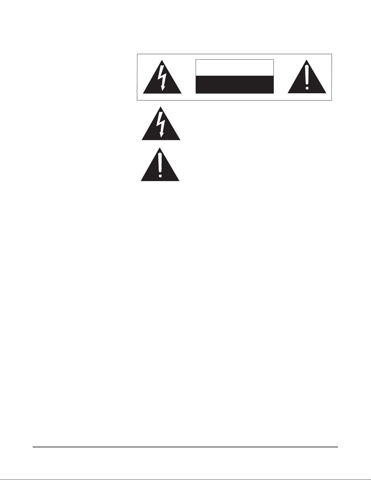
A single RCS-2700 unit has 8 sources of audio and 24 remote destinations, as
shown in Figure 1-1.
Figure 1-1: Sources and Destinations in a One-Unit Setup
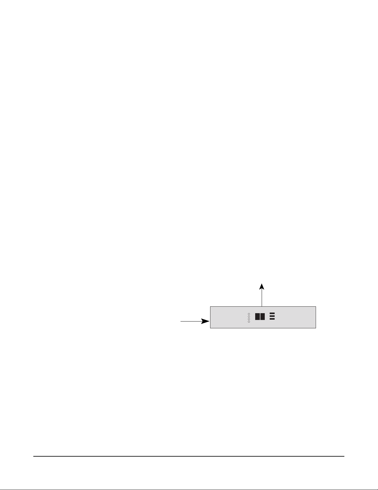
Two RCS-2700 units can be connected together to provide either 15 sources of
audio and 24 destinations or 8 sources of audio and 48 destinations as shown in
Figure 1-2. The address switch on the rear panel of each unit must be set with the
correct unit number to determine which configuration is chosen. Instructions for
setting and changing unit numbers are provided in the Installation Chapter.
1-2
RCS-2700 SOURCE ASSIGNMENT PANEL
Page 11
SOURCES 1-8
DESTINATIONS 1-24
DESTINATIONS 25- 48
SOURCES 1-7
DESTINATIONS 1-24
SOURCES 8-15
MAIN UNIT
UNIT 1
MAIN UNIT
Figure 1-2: Possible Configurations with Two RCS-2700 Units
UNIT 2
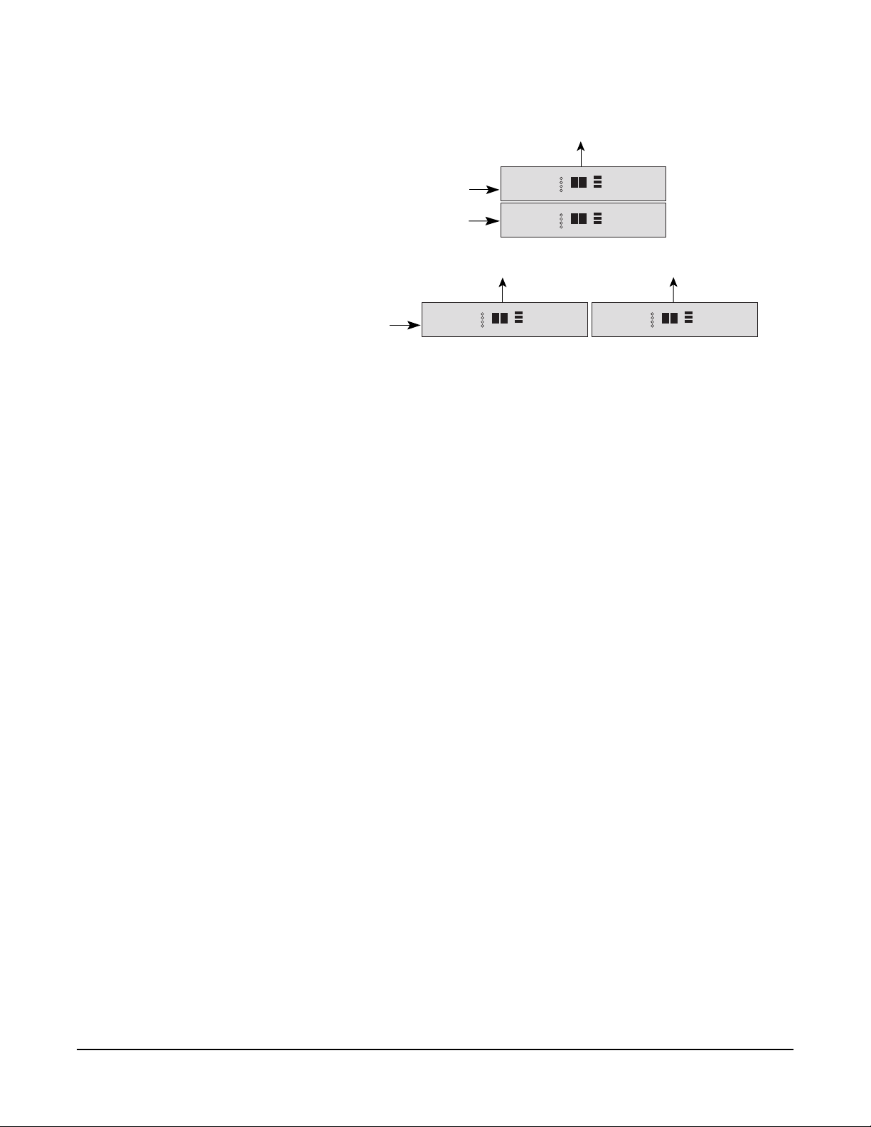
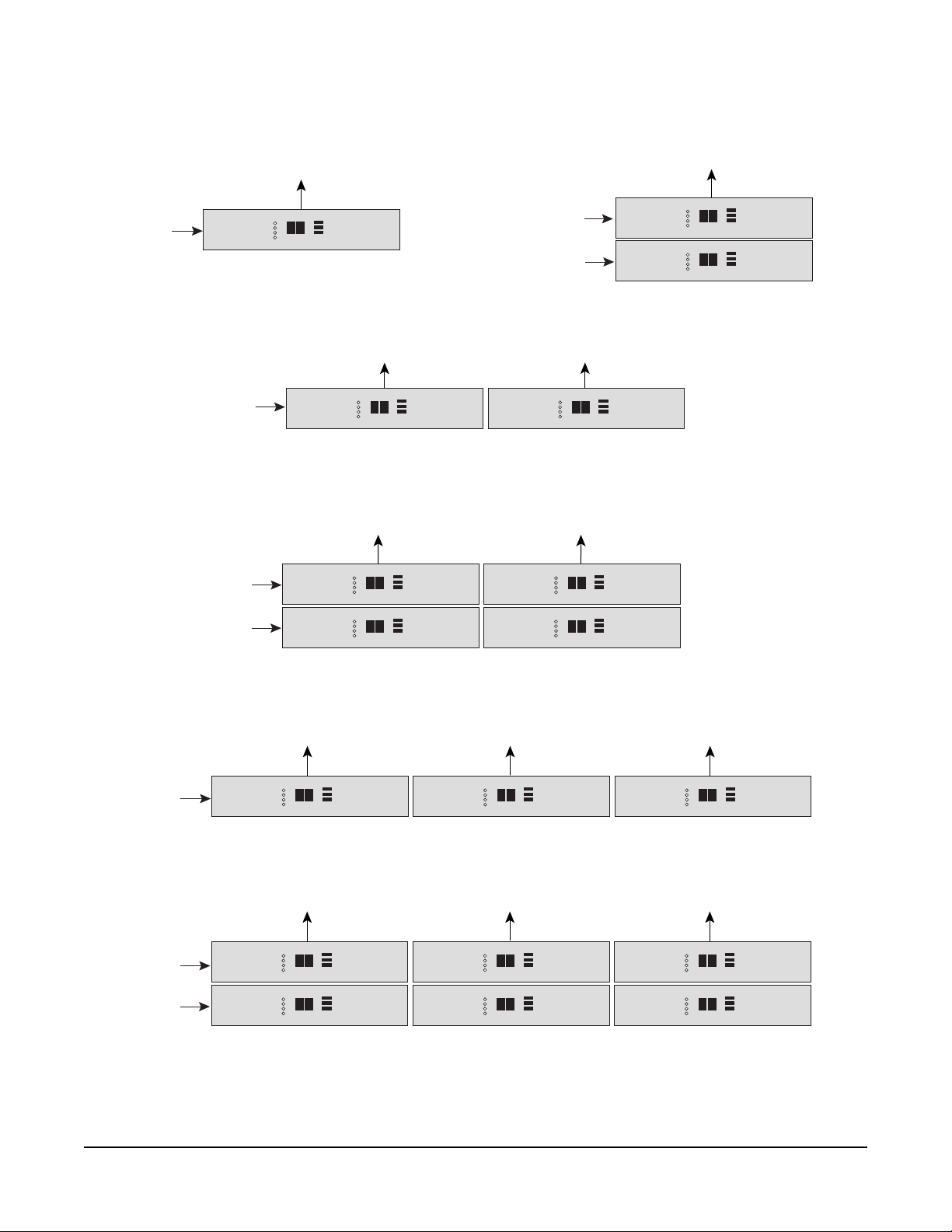
Other possible configurations include: 15 sources and 48 destinations (4 units),
8 sources and 72 destinations (3 units), and 15 sources and 72 destinations (6
units). Figure 1-3 illustrates all of the possible combinations of RCS-2700 units
with the correct unit numbers for each configuration.
For information on installing and wiring expansion units, and for setting unit
number addresses for each configuration, consult the Installation Chapter of this
manual.
ISO CHANNELS AND GROUPS
A single RCS-2700 unit has eight source channels available for use. If the main
source intercom station uses less than the eight available channels, the remaining
channels can still be used. For example, if a 4-channel MS-704 intercom station
provides the first four source channels, there will be four additional lines available
as source channels on the 8-channel RCS-2700.
These “virtual source channels” are called “ISO(lated)” channels, and the
destinations assigned to them are called “ISO” groups because they are not
connected to the main source intercom station. This in effect gives you four extra
channels to use, in addition to the four channels on the MS-704 source station,
offering a cost effective way to expand the functionality of your intercom system.
A typical application of an ISO channel is to allow two or three destinations to
talk to each other independently of the other destinations on a source channel.
To accomplish this, you assign the chosen destinations to an ISO channel as a
separate preset, or as a source/destination edit within the current preset.
A system can also be set up to work without a main station if all eight channels
are ISO channels. Destinations would be connected in the usual way and
assignments would be made between the eight ISO channels. System power is
still required.
RCS-2700 SOURCE ASSIGNMENT PANEL
1-3
Page 12
SOURCES 1-8
DESTINATIONS 1-24
MAIN UNIT
UNIT M
8 SOURCES X 24 DESTINATIONS
DESTINATIONS 1-24
SOURCES 1-8
SOURCES 1-7
MAIN UNIT
DESTINATIONS 1-24
MAIN UNIT
SOURCES 1-7
SOURCES 8-15
DESTINATIONS 25-48
UNIT M
8 SOURCES X 48 DESTINATIONS
DESTINATIONS 25-48
UNIT M
DESTINATIONS 1-24
MAIN UNIT
UNIT M
UNIT 1
15 SOURCES X 24 DESTINATIONS
UNIT 2
UNIT 2
SOURCES 1-8
SOURCES 1-7
SOURCES 8-15
SOURCES 8-15
MAIN UNIT
MAIN UNIT
DESTINATIONS 1-24
DESTINATIONS 1-24
UNIT 1
15 SOURCES X 48 DESTINATIONS
DESTINATIONS 25-48
UNIT M
8 SOURCES X 72 DESTINATIONS
DESTINATIONS 25-48
UNIT M
UNIT 1
15 SOURCES X 72 DESTINATIONS
UNIT 2
UNIT 2
UNIT 3
UNIT 3
DESTINATIONS 49-72
UNIT 4
DESTINATIONS 49-72
UNIT 4
UNIT 5
1-4
Figure 1-3: All Possible Configurations of RCS-2700 Units, with Unit Numbers for Each Configuration
RCS-2700 SOURCE ASSIGNMENT PANEL
Page 13
POWERING THE SYSTEM
POWERING A SINGLE RCS-2700 UNIT
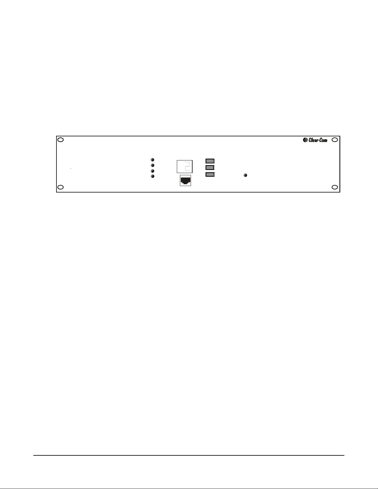
When a single RCS-2700 unit is powered, it goes through a start-up sequence
that takes five seconds to complete. During this time the green Power light and
red Fault light will be on. When the unit is ready for use, the green Power and
Data lights will be on and the red Fault light will be off. The current preset
number will appear on the front-panel display.
Remote
RCU-67
Select
Preset
Code
Lock/Unlock
Figure 1-4: RCS-2700 Front Panel
Locked
RCS-2700
Power
Data
Sys Exp
Fault
Preset/Code
POWERING MULTIPLE RCS-2700 UNITS
In a multi-unit configuration, the RCS-2700 main unit and all RCS-2700
expansion units must operate as one system, and therefore must all be powered
from the same power supply.
When the RCS-2700 units are powered, each unit will go through a start-up
sequence in which the system configuration is detected and validated. During
this time, each unit’s green Power light and red Fault light will be on. For the
main unit this sequence takes about five seconds, and for each expansion unit it
takes about two seconds.
At the conclusion of the start-up sequence, each expansion unit will display its
unit number as set by the address switch on the rear panel. Each expansion unit’s
Fault light will be off and the green Power, Data, and System Expansion lights
will be on.
When the main unit completes its start-up sequence successfully, it will display
the current preset number. The main unit’s Fault light will be off and its green
Send and Data lights will be on. If there are expansion units connected to the
main unit, the main unit’s green System Expansion light will be on.
If the main unit detects an invalid system configuration during the start-up
sequence, it will not complete the sequence. The main unit’s green Fault light
will be on and its green System Expansion light will flash. Expansion units will
display their addresses. To correct this condition, turn power to the system off,
adjust the address switches on the back of the expansion units according to the
numbers shown in Figure 1-3, and turn the power back on.
RCS-2700 SOURCE ASSIGNMENT PANEL
1-5
Page 14
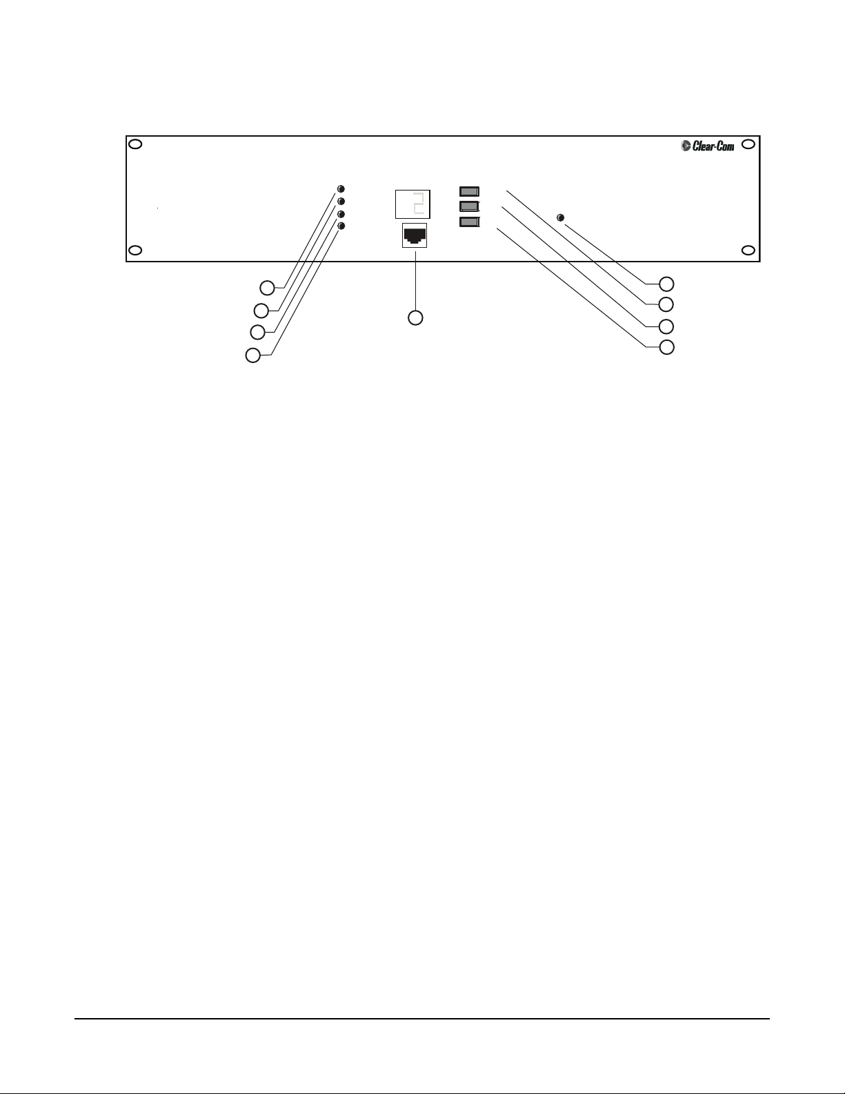
FRONT PANEL
System-Expansion Light
Fault Light
• You can change the
current preset in one of
four ways: from the front
panel of the RCS-2700,
with an RCU-67 Remote
Control Unit, with a
Windows-based PC, or
with a contact closure.
Power Light
Data Light
Remote
RCU-67
Select
Preset
Code
Lock/Unlock
Figure 1-5: RCS-2700 Front Panel
Locked
RCS 2700
5
Locked Light
6
Preset Button
7
Code Button
8
Lock/Unlock Button
Power
Data
Sys Exp
Fault
1
2
3
4
Preset/Code
9
Remote RCU-60 Jack
LIGHTS
Power Light (1)
When the green Power light is on, the unit is receiving DC power from the
intercom line or lines of a “source” intercom station or from an external power
supply.
Data Light (2)
When the green Data light is slowly blinking, the unit is transmitting or
receiving data from an attached RCU-67 Remote Control Unit or PC. When the
unit is ready to transmit or receive data, the green Data light will be on solidly.
System Expansion (“Sys Exp”) Light (3)
When the green System Expansion (“Sys Exp”) light is on solidly, the RCS-2700
main unit and all expansion units are properly connected in a multi-unit setup
and are communicating data. A blinking light, or no light, indicates a problem
such as an incorrect unit number in the multi-unit setup.
1-6
Fault Light (4)
When the red Fault light remains on after the start-up sequence, there is a
problem in a multi-unit setup such as a wiring problem or incorrect unit number.
Locked Light (5)
When the Locked light is on, the Preset button on the front panel of the
RCS-2700 is locked, and presets cannot be changed from the front panel. Presets
can be changed using an RCU-67 Remote Control Unit or a PC, however, even
if the Preset button is locked.
RCS-2700 SOURCE ASSIGNMENT PANEL
Page 15

PRESET BUTTON (6)
Preset Configurations (“Presets”)
A “preset” is a group of source/destination assignments that you store for current
or future use. The RCS-2700 unit’s memory can store 14 groups of
source/destination assignments. Each group is called a “preset.”
assignments are always made within one of the 14 presets. The desired preset must
be specified before making a source/destination assignment.
The number of source/destination assignments within a preset can be as few as
one destination assigned to one source or as many as 72 destinations assigned to
15 sources (in a multi-unit system).
When you receive your system, all 14 available presets are set to a default
configuration in which each destination is assigned to a source in numerical
order, as shown in Figure 1-6. You can then change the source/destination
assignments within each preset to suit your needs.
If at some point you want to set the system back to the default presets, you can
do so by using the Code-Reset button on the rear panel of the RCS-2700. See
“Using the Code-Reset Button” in the Installation Chapter for further
instructions.
Source/destination
SOURCES
DESTINATIONS
1 2 3 4 5 6 7 8 9 101112131415161718192021222324
1
xxx
2
3
4
5
6
7
8
xxx
xxx
xxx
xxx
xxx
xxx
xxx
Figure 1-6: Default Source/Destination Assignments
You initially program presets using a handheld RCU-67 Remote Control Unit or
a PC with RCS-WIN software. When you have programmed more than one
preset, you can select between presets in one of four ways: with the preset button
on the front panel of the RCS-2700; with a handheld RCU-67 Remote Control
Unit; with a contact closure; or with a PC that has the RCS-WIN software
installed.
RCS-2700 SOURCE ASSIGNMENT PANEL
1-7
Page 16

This chapter gives instructions for selecting a preset from the front panel of the
RCS-2700. For instructions on selecting or editing a preset with the RCU-67
Remote Control Unit, see the RCU-67 Remote Control Unit Instruction Manual.
For instructions on selecting, editing, or creating a preset with a Windows-based
PC, see the RCS-WIN Software Instruction Manual. For instructions on selecting
a preset with a contact closure, see “Wiring the Preset-Select Contact Closure” in
the Installation Chapter of this manual.
Selecting Presets from the Front Panel of the RCS-2700
• The RCU-67 Remote
Control Unit connects to
the RCS-2700 main unit
through up to 300 feet
(91 meters) of cable.
Category-5 cable is
recommended.
You can select which of the 14 presets will go into operation at any given time
with the Preset button on the front panel of the RCS-2700.
To select a preset from the front panel of the RCS-2700 unit:
1. Repeatedly press the Preset button to progress through the available preset
numbers until you reach the desired preset number.
The display will progress from one preset to the next, starting at 1 and ending
at 14. When it reaches preset 14, it will start again at preset 1.
2. When the desired preset number appears on the display, hold the Preset
button down until the display goes blank, then release the button.
Releasing the Preset button before the display goes blank will cancel the
change. This feature prevents accidental changes.
The RCS-2700 main and expansion units will then change to the newly selected
preset. When this change is complete, the main unit will display the new preset
number in the “Preset/Code” window.
The change to the preset will take about two seconds for each main or expansion
unit in the system. For example, changing a preset in a system with a main unit
and two expansion units will take about six seconds.
Note: When you change a preset, the RCS-2700 will switch destination and
source assignments within the unit, causing a clicking sound. This is normal.
1-8
CODE AND LOCK/UNLOCK BUTTONS (7 & 8)
You can lock the Preset button on the RCS-2700’s front panel to prevent
accidental or unauthorized changes to the selected preset from the front panel.
When you first receive your RCS-2700 unit, it is set to the factory default code of
“0.” When the code is set to “0” the RCS-2700’s Preset button cannot be locked.
If you do not want to use the lock feature, you can leave the RCS-2700 set to the
factory default code of “0.”
If you want to lock the RCS-2700’s Preset button, you must first change the code
from the “no-lock” code of “0” to another single-digit code called an “unlock”
code, and then lock the unit. See the following section “Changing the Unlock
Code” for instructions.
Changing the Unlock Code
The process of changing the unlock code is the same whether you are changing
from the factory default code of “0” to an unlock code, or changing from one
unlock code to another.
RCS-2700 SOURCE ASSIGNMENT PANEL
Page 17

• The preset button on the
RCS-2700 can be locked
to prevent unauthorized
or accidental changes.
Note: If the RCS-2700 unit’s Preset button is locked, you must unlock it first
before changing the unlock code. See the following section entitled “Unlocking the
RCS-2700” for instructions on unlocking the preset button. If the lock code is set
to the factory default “no-lock” code of “0” you do not need to unlock it.
To change the unlock code:
1. Press and simultaneously hold the Lock and Code buttons on the main unit
for three seconds until “L_” appears in the display. When “L_” appears in the
display, release the buttons.
2. Repeatedly press the Code button until the desired new code appears in the
display.
• The unlock code is a single-digit character. Note that, in addition to the
numbers 1-9, there are some alphabetic and special characters available
when choosing a code.
• If you release the Code button for three seconds before going on to the next
step, the unlock-code change is cancelled.
3. When the desired new code appears in the display, press and release the Lock
button.
Within a few seconds, the current preset number will reappear in the display.
• When an RCS-2700 is
purchased from
Clear-Com, it is set to the
“no-lock” code of 0 which
disables the preset-button
locking feature.
The unlock code is now changed. Write down the unlock code and keep it in a
safe place for future reference. If you forget or misplace the code, there are only a
limited number of ways to unlock the Preset button. For more information, see
the section entitled “Code-Reset Button” later in this chapter
Locking the RCS-2700
To lock the Preset button on the front panel of the RCS-2700:
• Press and hold the Lock button on the main unit for at least three seconds
until the Locked light comes on.
• If the code is set to the factory default “no-lock” code of “0” you will not be
able to lock the Preset button. When you press the Lock button, the Locked
light will not turn on. You must first change the code from “0” to a
single-digit unlock code, and then lock the unit. See the previous section
entitled “Changing the Unlock Code” for instructions and more
information.
The Preset button on the RCS-2700 is now locked. Note that the Lock button
only locks the Preset button on the RCS-2700 unit. Presets can still be changed
using the handheld RCU-67 Remote Control Unit or a PC even though the
RCS-2700 Preset button is locked.
Unlocking the RCS-2700
To unlock the Preset button, you must use the Code and Lock/Unlock buttons
on RCS-2700 unit’s front panel to enter an unlock code.
To unlock the Preset button on the front panel of the RCS-2700:
1. Press and hold the Code button on the main unit for three seconds until “C_”
appears on the display.
2. Repeatedly press the Code button until the correct unlock code appears.
RCS-2700 SOURCE ASSIGNMENT PANEL
1-9
Page 18

• If the lock light is on, you
cannot change the preset
from the front panel. For
security reasons you
cannot change the unlock
code either. You must
unlock the unit first.
If the Code button is released for three seconds before going to the next step,
the unlocking procedure is cancelled and the RCS-2700 remains locked.
3. When the correct code appears, press and release the Lock button.
Within a second or two, the Locked light will turn off and the current preset
number will appear on the display.
The Preset button on the RCS-2700 is now unlocked and you can select a new
preset. To lock the Preset button again, and keep the same unlock code, simply
press and hold the Lock button for three seconds.
REMOTE RCU-67 FRONT-PANEL JACK (9)
An RCU-67 Remote Control Unit can be plugged into the front-panel jack to
provide additional programming capability. The RCU-67 connects to the
RCS-2700 unit through Category-5 cable with RJ-45 connectors. The
RCS-2700 unit will recognize the presence of the RCU-67 and will begin
communicating with it after it has been plugged in for a few seconds.
While an RCU-67 is plugged into the front-panel jack, communication with a
PC or with a rear-panel connected RCU-67 will be suspended.
REAR PANEL
ADDRESS
RCU-67
B
A
5
PC SERIAL
1
Address Switch
2
Remote RCU-67 Jack
M
1
2
1 23456789101112131415161718192021222324
3
4
13
MTX
DATA
CONT
LINKS
PORT
1
DESTINATION POWER
14 15 16 17 18 19 20 21 22 23 24
2 3 4 5 6 7 8 9 10 11 12
3
4
5
DESTINATIONS
DESTINATIONS
Preset-Select Contact
Data Links
PC Serial Port
1
2345678
SOURCE POWER
1
SCE
RCS PWR
2 3 4 5 6 7 8
13
14 15 16 17 18 19 20 21 22 23 24
1
2 3 4 5 6 7 8 9 10 11 12
Code-Reset Button
SOURCES
SOURCE EXPANSIONS
SOURCE EXPANSIONS
Termination Switches
6
CODE RESET
123 84567
ON
OFF
TERMINATION
SWITCHES
7
Figure 1-7: RCS-2700 Rear Panel
ADDRESS SWITCH (1)
An RCS-2700 unit’s address switch is set when it is installed and should not be
changed unless the system is being reinstalled or reconfigured.
1-10
The position of this switch can be determined from the RCS-2700 unit’s
front-panel display. If the address switch is set to “M,” then the unit functions as
RCS-2700 SOURCE ASSIGNMENT PANEL
Page 19

a main unit and displays the preset number. If the address switch is set to 1, 2,
and so forth, then the unit functions as an expansion unit and displays the
expansion unit numbers “U1,” “U2,” and so forth on its front-panel display.
In a multi-unit setup, the main unit is the only unit that will display the
currently selected preset. All of the expansion units will display only their unit
number in the multi-unit setup.
• With the Code-Reset
button you can set the
RCS-2700 preset button
back to a “no-lock”
status.
Warning : Do not connect a
PC to the PC serial port
while an RCU-67 is
plugged into the jack on
the rear panel.
For more information on selecting or changing an address with the address
switch, see the section entitled “Setting the Address Switch” in the Installation
Chapter.
CODE-RESET BUTTON (2)
If you forget or misplace your unlock code, there are only three ways to unlock
the RCS-2700 unit’s Preset button without it:
• Try all 32 unlock codes.
• Use the Code-Reset button to restore all source/destination assignments to
their factory default positions. This will also reset the unlock code back to the
“unlock” code of 0. For instructions, see the section entitled “Using the
Code-Reset Button” in the Installation Chapter.
• Use the Code-Reset button in conjunction with a PC and RCS-WIN software
to set the unlock code back to the “unlock” code of 0 without changing the
source/destination assignments back to their factory default settings. For
instructions see the RCS-WIN Instruction Manual.
REMOTE RCU-67 REAR-PANEL JACK (3)
An additional RCU-67 Remote Control Unit can be connected to the rear panel
of the RCS-2700 unit. It connects to the RCS-2700 with Category-5 cable
terminated with RJ-45 connectors.
Only one RCU-67 Remote Control Unit can operate at any one time.
Communication with an RCU-67 connected to the rear-panel will be suspended
if an RCU-67 is plugged into the front-panel jack. The front-panel RCU-67
always takes precedence over the rear-panel RCU-67.
Warning:Do not connect a PC to the PC serial port while an RCU-67 is plugged
• The “preset-select”
contact closure allows you
to use an external device
such as a wall- or
panel-mounted button to
change presets.
RCS-2700 SOURCE ASSIGNMENT PANEL
PC SERIAL PORT (4)
For ultimate programming capability, you can connect a PC (Windows
95/98/ME/2000) to the PC serial port on the back of the RCS-2700 main unit.
You can then program the RCS-2700 directly from the PC. The PC must have
the RCS-WIN program installed.
Do not connect an RCU-67 Remote Control Unit while the PC is in use. If you
connect a front-panel RCU-67, communication to the PC will be suspended. If
into the rear-panel RCU-67 jack. Doing this will connect multiple
serial ports on the rear panel which are not designed to be connected.
Either one or both of the ports will not work.
1-11
Page 20

you connect a rear-panel RCU-67, you will have connected multiple serial ports
on the rear panel and either one or both of the ports will not work.
Refer to the Installation Chapter of this manual for further information
regarding the PC serial port.
PRESET-SELECT CONTACT CLOSURE (5)
You can wire the contact closure on the rear panel of the RCS-2700 so that you
can select presets by pressing external buttons or other devices.
Refer to the Installation Chapter for more detailed information on the wiring
and operation of this feature.
TERMINATION SWITCHES (6)
The termination switches are set by a technician when the RCS-2700 is installed
and should not be changed unless a specific need arises. If these switches are not
set correctly, very poor intercom operation can result. Refer to the section
entitled “Setting Termination Switches” in the Installation Chapter for guidelines
on setting these switches.
1-12
RCS-2700 SOURCE ASSIGNMENT PANEL
Page 21

2
• You connect the
RCS-2700 unit to source
channels, destinations,
expansion RCS-2700
units, and power.
INSTALLATION
UNPACKING THE RCS-2700
When you unpack the RCS-2700 Source Assignment Panel, you will find the
following items:
• RCS-2700 unit
• RCS-2700 manual
• 31 6-terminal Euro-block connectors
The Euro-block connectors press on to the rear-panel pins of the RCS-2700 unit.
They are used to wire the unit to destinations and sources. You can install the
connectors with the visible screws facing either upward or downward. However,
facing the screws upward, so that they are visible from above, allows more
flexibility in tightening the connections.
WIRING OVERVIEW
Four sets of pins on the rear panel of the RCS-2700 connect the unit to source
channels, destinations, expansion RCS-2700 units, and power.
ADDRESS
RCU-67
B
A
5
PC SERIAL
An overview of the wiring is given below, with more detailed explanations and
diagrams following later in the chapter.
2
Power Patch Panel
M
1
2
1 23456789101112131415161718192021222324
3
4
13
MTX
DATA
CONT
LINKS
PORT
1
DESTINATION POWER
14 15 16 17 18 19 20 21 22 23 24
2 3 4 5 6 7 8 9 10 11 12
DESTINATIONS
DESTINATIONS
1
2345678
SOURCE POWER
SCE
Destination Connections (Power and Audio)
3
Source Connections (Power and Audio)
1
RCS PWR
2 3 4 5 6 7 8
13
14 15 16 17 18 19 20 21 22 23 24
1
2 3 4 5 6 7 8 9 10 11 12
Source-8 Connection Points
Tie Together or Connect to Expansion Units
Figure 2-1: Four Sets of Connection Pins on the Rear Panel of an RCS-2700 Unit
1
SOURCES
SOURCE EXPANSIONS
SOURCE EXPANSIONS
4
CODE RESET
123 84567
TERMINATION
SWITCHES
ON
OFF
RCS-2700 SOURCE ASSIGNMENT PANEL
2-1
Page 22

• In a multi-unit setup, the
RCS-2700 main unit and
all RCS-2700 expansion
units must be powered by
the same channel on the
same power supply.
SOURCE CONNECTIONS (1)
You wire power and audio connections from the channels of a source intercom
station to the row of pins labeled “Sources” (1–8) on the rightmost upper corner
of the rear panel of the RCS-2700.
POWER PATCH PANEL CONNECTIONS (2)
The power patch panel links power from sources to destinations. The leftmost
upper two rows of pins on the rear panel of the RCS-2700 is the power patch
panel. The pins are labeled “Destination Power” and “Source Power.”
DESTINATION CONNECTIONS (3)
You wire power and audio to remote stations and beltpacks on the two rows of
pins labeled “Destinations” (1–24) in the rightmost lower corner of the rear
panel of the RCS-2700.
SOURCE EXPANSION CONNECTIONS (4)
You wire source-8 connection points to each other or to expansion RCS-2700
units on the two rows of pins labeled “Source Expansions” in the rightmost lower
corner of the rear panel of the RCS-2700.
You can wire these four sets of pins in any order. In multi-unit setups, however,
layering the wiring by beginning with the lower-level pins and moving upward is
more efficient.
POWERING THE RCS-2700 AND DESTINATIONS
POWERING FROM PARTY-LINE SOURCES
2-2
The first step in an installation is to determine how you are going to supply
power to the RCS-2700 unit and its connected remote stations and beltpacks.
The RCS-2700 unit and its connected remote devices are typically powered by
one or more channels of a main station or power supply. The RCS-2700 unit
itself uses very little power.
Although the system can be powered by one channel of a source station, this is
usually not recommended, especially for complex systems. Using multiple
channels to power the system provides for power redundancy in the case of
outages.
The source intercom station is typically a 2-, 4-, 8-, or 12-channel main or
master station. To power the entire system from a source station, the source
station must have an internal power supply.
Examples of stations that can power an entire system are Clear-Com’s MS-702
2-channel main station or its MS-704 4-channel main station. Two or more
stations can be used as source stations for one system if additional channels are
desired. For example, two MS-704 4-channel stations can be used to provide 8
source channels.
RCS-2 700 SOURCE ASSIGNMENT PANEL
Page 23

• The data cables between
expansion units should
not exceed 6 feet (2
meters) each.
A station without an internal power supply can still serve as a source station if an
external power supply is added. For example, Clear-Com’s RM-702 2-channel
remote station can serve as a source station if you add PS-702 (2-channel) or
PS-704 (4-channel) power supplies.
If expansion RCS-2700 units are added, the main unit and all expansion units
must be powered by the same channel on the same power supply so that the main
unit can correctly determine the size and configuration of the entire system.
Destinations can be powered from the power patch panel on the RCS-2700 or
from external power supplies. Power from pin 2 of each source channel is
connected internally to the respective “Source Power” connection in the power
power patch area. Destination power connections for each destination are
connected internally to pin 2 of the respective destination connections.
The connection scheme is very flexible, so there are a number of ways that power
can be patched. Strategies for providing power to the RCS-2700 main unit,
expansion units, and destinations are discussed in the following sections.
Powering from Multiple Party-Line Source Channels
Figure 2-2 shows how multiple source channels can power the RCS-2700 unit
and all connected remote destinations.
Each source channel powers three destinations. Power from the first source
channel powers the RCS-2700 unit and destinations 1, 2, and 3; power from the
second source channel powers destinations 4, 5, and 6; and so on through the
eighth source channel which powers destinations 22, 23 and 24.
The advantage of this connection strategy is that if the power for one destination
is shorted, it will only affect two others, assuming that the eight source power
channels are individually short protected.
When power is monitored with the RCU-67 Remote Control Unit or with the
PC, it will be possible to more closely detect which destination's power is shorted
because the short can be isolated to one of eight groups of destinations.
Figure 2-2: Powering the RCS-2700 from Multiple Source Channels
Powering from One Party-Line Source Channel
Figure 2-3 shows how power from one channel of the source intercom station
can power the RCS-2700 unit and all connected remote destinations.
RCS-2700 SOURCE ASSIGNMENT PANEL
2-3
Page 24

Power from the source intercom station’s one channel is patched to the power
Destination Power Channel Fuses or Circuit Breakers
connection for the RCS-2700 and to the power connections for all remote
destination stations.
The main advantage of this wiring is its simplicity. The disadvantage is that a
short on one destination’s cable can bring the whole system down. When power
monitoring is done with the RCU-67 or the RCS-WIN PC program, it will not
be possible to detect which destination's power is shorted.
Figure 2-3: Powering the RCS-2700 from a Single Source Channel
Powering from a Separate Power Supply
The third way of connecting power involves the use of a separate high-current 30
VDC power supply. The power supply is connected directly to the RCS-2700’s
power input connector, and fuses or circuit breakers are wired as shown in Figure
2-4 to protect each destination’s power circuit individually.
In this configuration, either an RCU-67 Remote Control Unit or a PC with the
RCS-WIN program installed will be able to detect precisely which destination’s
power circuit is shorted.
242322212019181716151413121110987654321
+30 VDC
Power Supply
Ground
Figure 2-4: Powering the RCS-2700 from an Individual Destination
2-4
RCS-2 700 SOURCE ASSIGNMENT PANEL
Page 25

POWERING FROM TW PARTY-LINE SOURCES
You can operate the RCS-2700 using TW party-line sources provided that each
source channel is powered. If power does not exist on every intercom channel,
you can add it using TWC-701 or TWC-704 TW Adapters. The wiring is as
shown in Figure 2-5. Because 2-amp relays are used, they can easily handle the
DC current on the line as they switch.
MS-704
4-Channel
Main Station
TWC-701 TWC-701 TWC-701 TWC-701
AAAATW TW TW TW
Shield
Source 4
Source 1
Source 2
Source 3
Main Unit
TW Destination
Channels
1 & 2 3 & 4 5 & 6 7 & 8 9 & 10 11 & 12
Shield
D C B A
3 (NC)
1 2
1 2 3
Turn MS-704
Channel
Terminations ON
Turn RCS-2700
Channel Terminations
1-4 OFF
When powering the stations this way, you should not connect the destination
power block to the source power block. Instead, connect a jumper wire on each
destination output using the connection options shown in Figure 2-5.
You can take RCS-2700 power from one of the source channels using the power
patch panel. The current drain of the RCS-2700 is designed not to interfere with
the audio on the powered source. You connect a jumper from the desired source
RCS-2700 SOURCE ASSIGNMENT PANEL
Figure 2-5: TW Source Wiring for a 4-Source System
2-5
Page 26

in the source power block to the RCS power connection. You must also add a
+30 VDC
jumper between the pin-2 and pin-3 (or the pin-5 and pin-6) connections for the
selected source in the sources block. In Figure 2-6, power from Source 8 is being
used to power the RCS-2700.
Figure 2-6: Powering the RCS-2700 from Source 8
Table 1 gives the pin assignments for wiring RTS source channels.
PIN# FUNCTION
Pin#1 Ground
Pin#2 No connection
Pin#3 Channel B
Pin#4 No connection
Pin#5 No connection
Pin#5 Channel A
Table 2-1: Pinouts for Wiring RTS Source Channels
POWERING THE RCS-2700 FROM A SEPARATE POWER SUPPLY
It is not essential that you power the RCS-2700 unit from the same supply as the
rest of the intercom system. Similarly, if you use the RCS-2700 to switch signals
in a non-intercom application, there may be no intercom power supply and the
destinations will not need +30 VDC power. The following figure shows the
connections needed to power the RCS-2700 from a separate 30 VDC supply.
Power Supply Ground
2-6
Figure 2-7: Powering the RCS-2700 from a Separate Power Supply
RCS-2 700 SOURCE ASSIGNMENT PANEL
Page 27

1
Address Switch
3
Remote RCU-67 Jack
CONNECTING AND SETTING REAR PANEL CONTROLS
Code-Reset Button
2
ADDRESS
RCU-67
B
A
5
PC SERIAL
CODE RESET
M
1
2
1 23456789101112131415161718192021222324
3
4
13
MTX
DATA
CONT
LINKS
PORT
1
DESTINATION POWER
14 15 16 17 18 19 20 21 22 23 24
2 3 4 5 6 7 8 9 10 11 12
6
5
4
DESTINATIONS
DESTINATIONS
Preset-Select Contact
Data Links
PC Serial Port
1
2345678
SOURCE POWER
1
SCE
RCS PWR
2 3 4 5 6 7 8
13
14 15 16 17 18 19 20 21 22 23 24
1
2 3 4 5 6 7 8 9 10 11 12
SOURCES
SOURCE EXPANSIONS
SOURCE EXPANSIONS
Termination Switches
123 84567
ON
OFF
TERMINATION
SWITCHES
7
Figure 2-8: RCS-2700 Rear Panel
SETTING THE ADDRESS SWITCH (1)
Setting the Address Switch for a Single-Unit System
If you are using one RCS-2700 unit, the address switch should be set to “M” for
main unit. This is the factory default setting that the unit is shipped with, so no
changes are necessary to the address switch if you are using one RCS-2700 unit.
Setting Address Switches in a Multi-Unit System
In a multi-unit system, each RCS-2700 unit must be defined as a main unit or an
expansion unit in the switching array. Since all RCS-2700 units are identical
electronically, setting their address switches is the only way to define their unique
functions in a multi-unit setup.
When the system is installed, you turn the address switch to the unit numbers
shown in Figure 2-9.
RCS-2700 SOURCE ASSIGNMENT PANEL
2-7
Page 28

Main Unit
M
4
2A
Sources 1–8 (1–7*)
Destinations 1–24
Unit 2
Sources 1–8 (1–7*)
Destinations 25–48
Unit 4
Sources 1–8 (1–7*)
Destinations 49–72
Unit 1
Sources 8–15
Destinations 1–24
* If Unit 1 exists, then the Main Unit and Units 2 and 4 connect to Sources 1–7 instead of 1–8.
Figure 2-9: Unit Numbers
Note: Before setting an address switch to the desired unit number, you must turn
the power to the system off. When the system is powered back up, the changes to
unit numbers take effect.
To set the address switch to the desired unit number:
1. Turn the power to the RCS-2700 unit off.
2. Use a small flat-bladed screwdriver to turn the rotary address switch to the
correct unit number.
3. Set the switch to “M” for the main unit, “1” for expansion unit 1, “2” for
expansion unit 2, and so on.
• The “A” and “B” positions should not be used. They are reserved for factory
testing.
• Note that the small arrow on the shaft of the switch indicates the selected
position. For example, in the figure shown below, the switch is set to “M.” It
is not set to “2” or “A.”
Unit 3
Sources 8–15
Destinations 25–48
Unit 5
Sources 8–15
Destinations 49–72
2-8
B
1
35
Figure 2-10: Address Switch
4. Turn the power to the unit back on.
The front-panel “Preset/Code” window will indicate whether the unit is a
main or expansion unit. A main unit will show the current preset number in
the display. An expansion unit, however, will always show only its unit
number on the front-panel display.
USING THE CODE-RESET BUTTON (2)
The Code-Reset button has two functions. You can use it to set the RCS-2700
back to a “no-lock” status if you have forgotten your unlock code. To do this you
RCS-2 700 SOURCE ASSIGNMENT PANEL
Page 29

need a PC with the RCS-WIN program installed. For detailed instructions, see
the RCS-WIN Instruction Manual.
The second function of the Code-Reset button is to return a main or expansion
unit to its factory default settings. If there are presets defined and set, or source
and destination names entered, they will all be erased when this function is used.
This function must therefore only be performed with careful consideration. This
function only affects the main or expansion unit it is performed upon; it does not
affect an entire system. Setting a unit back to its factory default settings will also
set the unlock code for that unit back to the “no-lock” code of 0.
Warning:The following steps will completely erase all programmed settings and
return the main or expansion unit to the factory default settings.
To return an RCS-2700 unit to the factory default settings:
1. Turn power to the unit off.
2. Press and hold the Code-Reset button.
3. Turn power to the unit on while continuing to hold the Code-Reset button.
4. Release the Code-Reset button when the front-panel display reads “CC.”
5. If the Locked light remains on, turn power to the unit off and then on again.
After a few seconds, the start-up sequence will begin and the factory default
settings will be restored.
Warning : Do not connect a
PC and an RCU-67
Remote Control Unit to
the RCS-2700 unit at the
same time.
CONNECTING A REMOTE RCU-67 (3)
For additional programming capability, you can connect an RCU-67 Remote
Control Unit to the rear-panel jack provided for it. The RCS-2700 will recognize
the RCU-67 and begin communicating with it a few seconds after it is
connected.
Only one RCU-67 Remote Control Unit can operate at any one time. If at any
one time two RCU-67s are connected, only the front-panel RCU-67 will
operate. The RCU-67 connected to the front-panel jack always takes precedence
over the RCU-67 connected to the rear-panel jack.
Warning:Do not connect a PC to the PC serial port while an RCU-67 Remote
Control Unit is plugged into the jack on the rear panel. Doing this will
connect multiple serial ports which are not designed to be connected.
Either one or both of the ports will not work.
CONNECTING A PC (4)
For ultimate programming capability, you can connect a PC to the PC serial port
on the back of the main RCS-2700 unit. You can then program the RCS-2700
directly from the PC. The PC must have the RCS-WIN program installed.
Communication with the PC will be suspended if an RCU-67 Remote Control
Unit is plugged into the front-panel jack.
Warning:Do not connect an RCU-67 Remote Control Unit to the rear-panel jack
RCS-2700 SOURCE ASSIGNMENT PANEL
while a PC is connected to the serial port. Doing this will connect
2-9
Page 30

multiple serial ports which are not designed to be connected. Either one
or both of the ports will not work.
The communication interface is RS-232D and the settings are:
• 19200 baud
•1 start bit
•8 data bits
•1 stop bits
•no parity
The RS-232D interface has a distance limitation of 300 feet of cable (91 meters),
but this is subject to the quality of the wiring used and the presence of electrical
noise and interference along the cable run. The pinout of the DB-9F serial port
connector on the rear panel is shown in the Table 2-2 below:
PIN SIGNAL FUNCTION
1 CF Received Line Signal Detector (not used)
2 RXD Serial data from the RCS-2700 to the PC
3 TXD Serial data from the PC to the RCS-2700
4 DTR Data Terminal Ready (connected to DSR)
• The data links pairs
connect the main unit to
expansion units.
5GNDSignal ground
6 DSR Data Set Ready (connected to DTR)
7 RTS Request to Send (connected to CTS)
8 CTS Clear to Send (connected to RTS)
9 RI Ring Indicator (not used)
Table 2-2: Pinout of DB-9F Serial Port Connector
WIRING THE DATA-LINKS CONNECTORS TO EXPANSION UNITS (5)
Two data-link pairs are provided on the rear panel of each RCS-2700 for
connecting expansion units to the main unit. A single-pair connection between
the main unit and each expansion unit is required so that the main unit can
direct the operation of the system as a whole. This is a bi-directional, parallel
connection, and the two data-link pairs are connected together internally, so
there is no “in” or “out” connection per se. Note the location of the ground and
data connection pins in the following diagram.
2-10
RCS-2 700 SOURCE ASSIGNMENT PANEL
Page 31

CONTACT
G
Data
U5
S
S
round
DATA
LINKS
PRESET
SELECT
Figure 2-11: Ground and Data Connections for Linking RCS-2700 Units
You can “daisy-chain” the connections from unit to unit to connect all of the
units together. Use wires of two different colors to connect the ground and data
pins from unit to unit. You can use twisted pair or shielded wire. If you use
shielded wire, connect the shield to the ground pin.
The length of each section of wire between units should be less than 6 feet (2
meters), although typically less than a foot of wire (30 centimeters) should be all
that is necessary. The units should be linked as shown in the Figure 2-12. It does
not matter in what order the main and numbered expansion units are connected,
although connecting the units in numbered order should result in an installation
that is more organized.
hield
M
U1
U2
U3
hield
Figure 2-12: RCS-2700 Units are “Daisy-Chained” Together
RCS-2700 SOURCE ASSIGNMENT PANEL
U4
2-11
Page 32

WIRING THE PRESET-SELECT CONTACT CLOSURE (6)
T
G
• You can use button or
relay contacts to select
presets.
The contact closure on the rear panel labeled “Preset-Select Contact” allows you
to wire button or relay contacts to select presets. To use this feature, connect
normally open button or relay contacts, or a +5 VDC (active low) logic output,
to these contacts. For logic connections, note the ground and signal connections
shown in Figure 2-13.
Signal
round
DATA
LINKS
Figure 2-13: Ground and Signal Connections for a Logic-Output Device
To select a preset with a contact closure:
PRESET
SELECT
CONTAC
1. Close the contact the number of times that equals the desired preset number.
Close the contact once for preset 1, twice for preset 2, and so on.
2. Hold each connection for at least three seconds.
3. Release the contacts.
The RCS-2700 will change to the selected preset.
If the sequence of contact closures stops with an open condition for two seconds,
the change is cancelled. Each time a new sequence of contact closures is initiated,
the counting begins from “1.” Selecting a preset with a contact closure in this
way allows you to know which preset you have selected without visual indicators.
The timing of the contact closure is as follows:
• Counting contact closure: .25 to 1 second
• Release time between counting contact closures: .25 to 1 second
• Contact closure time required to enable preset change: 3 seconds or more
Note that all Clear-Com PL main stations and some remote stations have a
contact closure triggered by the stage announce button. If the stage announce
button is not being used for other purposes, it can serve as a preset-select
connection for the RCS-2700.
You can select a preset with a preset-select contact even when a PC or RCU-67 is
connected to the RCS-2700 unit at the same time. You can also select a preset
when the RCS-2700 unit’s front-panel preset button is locked.
SETTING TERMINATION SWITCHES (7)
Each Clear-Com party-line channel requires one and only one termination. The
RCS-2700 provides switchable terminations at the source connections.
Therefore, terminations for party-line channels coming from main stations or
power supplies should be turned off at those sources to allow the RCS-2700 to
provide the terminations. There will be less crosstalk and noise on the intercom
2-12
RCS-2 700 SOURCE ASSIGNMENT PANEL
Page 33

lines if the terminations are located at the RCS-2700 rather than at the main
stations or power supplies.
Terminations for each source channel should be switched on only at the
RCS-2700 main unit and expansion unit 1. Termination switches on all other
RCS-2700 expansion units should be switched off.
If there are unused source channels on any unit, the terminations to those source
channels should be turned on.
When the RCS-2700 is used for general switching of devices other than
Clear-Com party lines, the termination switches on all of the units should be
turned off.
DEVICE TERMINATION SWITCH
Main source station off
Power supply off
RCS-2700 main unit on
RCS-2700 expansion unit 1 on
All other RCS-2700 expansion units off
Any unused source channel on any unit on
Table 2-3: Termination Switch Settings
• Source-8 pins must be
wired together in a
single-unit system, or
wired to another
RCS-2700 unit in a
multi-unit system.
WIRING SOURCE CHANNELS
BASIC SWITCHING THEORY
Figure 2-14 is a schematic diagram of an RCS-2700 switching block. Under
microprocessor control, the switching block can move a destination between
sources 1 through 8.
To Destination 1
Source 1
Source 2
Source 3
Source 4
Source 5
Source 6
Source 7
Source 8
Figure 2-14: Basic RCS-2700 Switching Block
Connection points for sources 1 through 7 are internally wired together.
Connection points for source 8 are not internally wired together, but are wired
outward instead, to pins on the rear panel of the RCS-2700 unit. This is done so
that source 8 can serve as a bridge to an expansion RCS-2700 unit, if necessary.
RCS-2700 SOURCE ASSIGNMENT PANEL
2-13
Page 34

To Des tination 1
Source 1
Source 2
Source 3
Source 4
Source 5
Source 6
Source 7
Source 8
To Des tination 2
Source 1
Source 2
Source 3
Source 4
Source 5
Source 6
Source 7
Source 8
To Des tination 3
Source 1
Source 2
Source 3
Source 4
Source 5
Source 6
Source 7
Source 8
To Des tination 24
Source 1
Source 2
Source 3
Source 4
Source 5
Source 6
Source 7
Source 8
In a single-unit system, source 8
connection points must be manually
connected on the rear panel of the
RCS-2700 unit
Figure 2-15: Multiple Switching Blocks in One RCS-2700 Unit
In a single-unit system, the source-8 pins on the rear panel of the RCS-2700
must be manually wired together in order for source 8 to work properly. In a
multi-unit system, the source-8 pins on the first, or main, unit must be wired to
source-connection pins on the next RCS-2700 unit in the system, and so on, to
allow for expansion of the number of sources.
• The RCS-2700 can be
used for switching
applications not limited to
intercom.
When an RCS-2700 main unit is connected to one expansion RCS-2700 unit,
the resulting system will be able to switch 24 destinations to 15 sources. The
switching blocks in the two units combine as shown in Figure 2-16. Note that
the source-8 connection points on the main unit (the upper unit in the diagram)
are not connected together, but are connected instead to the source connection
points on the expansion unit (the lower unit in the diagram). Note also that the
source-15 connection points on the expansion unit are not connected in the
diagram, to indicate that they must be manually wired together on the rear panel
of the expansion unit. (See Figure 2-17 and Figure 2-18 for examples of
rear-panel wiring.)
2-14
RCS-2 700 SOURCE ASSIGNMENT PANEL
Page 35

To Destination 1
Source 1
Source 2
Source 3
Source 4
Source 5
Source 6
Source 7
To Destination 2
Source 1
Source 2
Source 3
Source 4
Source 5
Source 6
Source 7
To Destination 3
Source 1
Source 2
Source 3
Source 4
Source 5
Source 6
Source 7
To Destination 24
Source 1
Source 2
Source 3
Source 4
Source 5
Source 6
Source 7
Source 8
Source 9
Source 10
Source 11
Source 12
Source 13
Source 14
Source 15
Source 8
Source 9
Source 10
Source 11
Source 12
Source 13
Source 14
Source 15
Source-8 connection points
have moved from main unit to
expansion unit
Source 8
Source 9
Source 10
Source 11
Source 12
Source 13
Source 14
Source 15
Source-15 connection points must be
manually wired together on the rear panel
of the expansion unit
Figure 2-16: Switching Block Configuration in a Two-Unit System
All source/destination connections are maintained even when the RCS-2700 is
not powered. The switched connections are isolated from any other internal
wiring and are rated at two amperes. Consequently, the RCS-2700 can be used
for switching applications not limited to intercom. In addition to party-line
intercom, other applications include 70-volt speaker switching and industrial
applications limited only by the designer’s imagination.
WIRING SOURCE CHANNELS IN AN 8-SOURCE SYSTEM
Wiring Source Channels
Source 8
Source 9
Source 10
Source 11
Source 12
Source 13
Source 14
Source 15
In 8-source systems, the source channels are wired as shown in Figure 2-17. The
pinout to the XLR cables connecting to main stations or power supply channels
is simply 1-2-3 from left to right. Pin 3 is the switched connection.
Wiring Source-8 Connection Points
The source-8 connection points, which have been wired out to pins on the rear
panel labeled “source expansions” (as explained in the previous section, “Basic
Switching Theory”) must now be wired together as shown in Figure 2-17. The
leftmost wire coming from the source expansion connector in the diagram
connects the joined sources to source 8 and its termination. The same source
wiring applies to expansion units 2 and 4, if they are used.
RCS-2700 SOURCE ASSIGNMENT PANEL
2-15
Page 36

Source 8
Main Unit
Source 7
Source 6
Shield
1 2 3
Source 5
Source 4
Source 3
Source 2
Source 1
Figure 2-17: Source Wiring for an 8-Source System
WIRING SOURCE CHANNELS IN A 15-SOURCE SYSTEM
Wiring Source-8 Connection Points to Expansion Unit 1
Figure 2-18 shows how 15-source systems must be wired. The source-expansion
pins of the main unit must be wired to expansion unit 1. Source 8 connects to
unit 1 and the source-8 connections on the main unit are left disconnected. This
wiring also applies to expansion units 2 and 3, as well as expansion units 4 and 5,
if used. Also shown in Figure 2-18 is the data-link connection between the main
unit and unit 1.
WIRING SOURCE CHANNELS IN A 48- OR 72-DESTINATION SYSTEM
Wiring Source-8 Connection Points to Expansion Units
In 48- or 72-destination systems, the wiring shown in the Figure 2-19 must be
added to join the sources of the main unit to the sources of unit 2. In
72-destination systems, this wiring must also be added between unit 2 and unit
4. Also shown in the diagram is the data-link connection between the units. Note
that the termination switches should be turned on in the main unit only, not in
unit 2 or unit 4.
In 15-source systems with 48 or 72 destinations, this wiring should also be added
between units 1, 3, and 5. Similarly, the termination switches in unit 1 should be
turned on, while the termination switches in units 3 and 5 should be turned off.
2-16
RCS-2 700 SOURCE ASSIGNMENT PANEL
Page 37

Source 7
Main Unit
ld
Shield
Shield
1 2 3
24 Shielded
Source
Expansion Wires
Source 6
Source 5
Source 4
Source 3
Source 2
Source 1
Source 15
Source 14
Source 13
Source 12
Source 11
Source 10
Source 9
Source 8
Termination
Switches ON
Shie
Termination
Switches ON
Expansion Unit 1
RCS-2700 SOURCE ASSIGNMENT PANEL
Figure 2-18: Source Wiring for a 15-Source System
2-17
Page 38

Main Unit
Source 8
F
Shield
1 2 3
Source 7
Source 6
Source 5
Source 4
Source 3
Source 2
Source 1
Termination
Switches ON
Shield
Expansion Unit 2
Shield
Shield
1 2 3
Termination
Switches OF
1 2 3
Figure 2-19: Source Wiring for a 48- or 72-Destination System
2-18
RCS-2 700 SOURCE ASSIGNMENT PANEL
Page 39

WIRING DESTINATIONS
Destinations
You wire destinations to the main unit and to expansion units 2 and 4, if they
exist. The pinout to the XLR cables connecting to beltpacks and other stations is
simply 1-2-3 from left to right. Pin 3 is the switched connection.
You use the 3-pin XLR connector in 2-wire intercom systems for cabling stations
and beltpacks together. Pin 1 is ground, pin 2 carries power (and sometimes
audio), and pin 3 carries audio (and sometimes power). When a destination is
connected to the RCS-2700, the RCS-2700 is actually switching the destination’s
pin-3 audio connection to one of the sources. The pin-2 connections (which
carry power) and the pin-1 connections do not switch.
Main Unit
123456789101112
Destinations
Shield
1 2 3
12 13 14 15 16 17 18 19 21 22 23 24
Figure 2-20: Connection Wiring to Destinations
You can wire the destination connections for conventional single-channel
Clear-Com party lines or for two-channel TW party lines. The wiring difference
is as follows:
RCS-2700 SOURCE ASSIGNMENT PANEL
2-19
Page 40

1
3
2
1
23
1
23
123456
2-Channel
TW Wiring
123456
Single-Channel
Wiring
Figure 2-21: Connection Wiring for 1-Channel and 2-Channel Destinations
Note that if you want to monitor power with RCS-WIN or with an RCU-67,
you must jumper pin 3 to pin 2, and jumper pin 6 to pin 5.
2-20
RCS-2 700 SOURCE ASSIGNMENT PANEL
Page 41

WIRING SUMMARY FOR 8-SOURCE SYSTEMS
The following table shows the basic groups of connections that form various
sized 8-source systems. Check that the wiring indicated for each topic has been
performed. Refer to wiring diagrams elsewhere in this chapter for the detailed
connections.
BASIC WIRING FOR 24-DESTINATION,
8-SOURCE SYSTEM
MAIN UNIT UNIT 2 UNIT 4
ADDRESS
SOURCES
DESTINATIONS
TER MINAT ION
SWITCHES
SOURCE EXPANSIONS
DESTINATION POWER
(SINGLE CHANNEL)
DESTINATION POWER
(2-CHANNEL TW)
RCS POWER
DATA LINK
M2 4
1–8 1–8 1–8
1–24 25–48 49–72
On Off* Off*
Tied together Tied together Tied together
+30 VDC +30 VDC +30 VDC
No connection** No connection** No connection**
+30 VDC +30 VDC +30 VDC
To Unit 2 To Unit 4 Last connection
*Exceptions are unconnected source channels, which should be set to on.
ADDITIONAL WIRING
FOR 48 DESTINATIONS
Table 2-4: Wiring Configurations for an 8-Source System
ADDITIONAL WIRING FOR
72 DESTINATIONS
**If you want to monitor power with RCS-WIN or with an RCU-67 Remote
Control Unit, you must jumper pin 3 to pin 2, and jumper pin 6 to pin 5.
RCS-2700 SOURCE ASSIGNMENT PANEL
2-21
Page 42

WIRING SUMMARY FOR 15-SOURCE SYSTEMS
The following table shows the basic groups of connections that form various
sized 15-source systems. Check that the wiring indicated for each topic has been
performed. Refer to wiring diagrams elsewhere in this chapter for the detailed
connections.
BASIC WIRING FOR 24-DESTINATION, 15-SOURCE
SYSTEM
MAIN UNIT UNIT 1 UNIT 2 UNIT 3 UNIT 4 UNIT 5
ADDRESS
SOURCES
DESTINATIONS
M12 34 5
1–7 8–15 1–7 8–15 1–7 8–15
1–24 Source
expansions
from main
unit
TERMINATION
SWITCHES
SOURCE
EXPANSIONS
DESTINATION
POWER (SINGLE
CHANNEL)
DESTINATION
POWER
On On Off* Off* Off* Off*
To u n it 1
Tied together To unit 3
destinations
+30 VDC No
connection
No
connection**
No
connection**
ADDITIONAL WIRING FOR 48
DESTINATIONS
25–48 Source
expansions
from unit 2
Tied together To unit 5
destinations
+30 VDC No
connection
No
connection**
No
connection**
ADDITIONAL WIRING FOR 72
DESTINATIONS
49–72 Source
expansions
from unit 4
Tied together
destinations
+30 VDC No
connection
No
connection**
No
connection**
(2-CHANNEL TW)
RCS POWER
DATA LINK
2-22
+30 VDC +30 VDC +30 VDC +30 VDC +30 VDC +30 VDC
To unit 1 To unit 2 To unit 3 To unit 4 To unit 5 Last
connection
Table 2-5: Wiring Configurations for a 15-Source System
* Exceptions are unconnected source channels, which should be set to “on.”
* *If you want to monitor power with RCS-WIN or with an RCU-67 Remote
Control Unit, you must jumper pin 3 to pin 2, and jumper pin 6 to pin 5.
RCS-2 700 SOURCE ASSIGNMENT PANEL
Page 43

3
SYMPTOM CAUSE SOLUTION
MAINTENANCE
TROUBLESHOOTING TIPS
Listed below are some of the more common problems the RCS-2700 may experience,
their possible causes, and suggested solutions.
RCS-2700 fault light
remains on after start-up
sequence and system
expansion light is blinking.
If destination does not
change to source that you
intended.
System configuration is set up
incorrectly.
Incorrect power input. Make sure power input is 30 V ±
1. First, turn power to the
system off.
2. Check that address switches
are set to correct unit numbers.
See Figure 1-3 in the Operations
Chapter for correct unit
numbers.
10% (27–33 V) at all times. You
can power the unit from a
separate 30 VDC power supply.
RCS-2700 SOURCE ASSIGNMENT PANEL
3-1
Page 44

BLOCK DIAGRAM
EXPANSION
INTERFACE
PC / RCU-67
INTERFACE
24 DESTINATIONS
8 SOURCES
SWITCHING MATRIX
TEST
INTERFACE
VOLTAGE
REGULATOR
TW POWER
ADAPTOR
COMMUNICATIONS/USER
INTERFACE
MICROPROCESSOR
FRONT PANEL
DISPLAYS AND
BUTTONS
INTERCOM POWER PATCH PANEL
24 MONITORED POWER INPUTS
Figure 3-1: RCS-2700 Block Diagram
TEST
INTERFACE
MEMORY/ INPUT/OUTPUT
MICROPROCESSOR
BACK PANEL
SWITCHES
AND INPUTS
POWER
MONITORING
CIRCUITS
3-2
RCS-2700 SOURCE ASSIGNMENT PANEL
Page 45

4
GLOSSARY
Channel: A two-way talk path.
Destination: An intercom station, beltpack, or interface (or group of such
devices connected together) which is assigned to a source channel of a central
intercom station. Destination stations do not have their own power supply, and
are typically powered by the central intercom station.
Download: In traditional computer terminology, to download data means to
transfer data from a large computer’s memory to the memory of another device,
usually a smaller computer. In this manual, to download data specifically means
to transfer data from the RCS-2700 unit’s memory to RCS-WIN where it will
display on the computer screen.
ISO: The ISO function allows a member on a party line to speak privately to
another member on the party line.
Main Station: A multi-channel intercom station with an internal power supply
which can provide power both to itself and to all of the remote stations
connected to it.
Master Station: A multi-channel intercom station with an internal power supply
which can provide power to itself but not to any of the remote stations connected
to it.
Null: (noun) 1. Adjustment that controls the amount of sidetone heard by the
user. 2. The degree of sidetone adjustment. (verb) To adjust the amount of
sidetone heard by the user.
Online: In general computer terminology online means connected to a
computer or telecommunications system. Specifically in this manual it means
that RCS-WIN is connected to the RCS-2700 unit so that data can be
transferred between them.
Offline: In general computer terminology offline means not connected to a
computer or telecommunications system or operating independently of such a
system. Specifically in this manual, offline means that RCS-WIN is not actively
connected to the RCS-2700 and therefore cannot send data to and from the
RCS-2700 unit. Even though RCS-WIN is offline to the RCS-2700 unit, it can
still be programmed with source/destination assignments that can be applied
when it goes online to the RCS-2700 unit.
Party Line: Intercom channel on which each member can both listen and speak
to every other member on the channel. Analogous to a telephone conference call
with its two-way, full duplex communication.
Preset: A preset is a group of source/destination assignments that you create for
current or future use. The RCS-2700 Source Assignment Panel can store up to
14 presets. All source/destination assignments are made within a preset.
RCS-2700 SOURCE ASSIGNMENT PANEL
4-1
Page 46

Preset Button: A button on the Source Assignment Screen that you click to select
a particular preset.
Remote Station: See Destination.
Sidetone: The sound of your own voice transmitted through an earphone as you
speak.
Source: One of the channels of a main or master station to which remote stations
or beltpacks (generally one or two-channel devices) are assigned. Once a remote
station is assigned to a source channel, that station’s operator can both talk and
listen to all other stations on the channel.
Source/Destination Assignment: The assignment of a destination to a particular
source channel.
Upload: In traditional computer terminology, to upload data means to transfer
data from a microcomputer to a remote computer, usually through a modem. In
this manual, to upload data specifically means to transfer data from RCS-WIN to
the RCS-2700 unit’s memory.
4-2
RCS-2700 SOURCE ASSIGNMENT PANEL
Page 47

5
SPECIFICATIONS
0 dBu is referenced to 0.775 volts RMS
RCS-2700 PROGRAMMABLE SOURCE ASSIGNMENT PANEL
Audio
Party-line intercom 20 - 20KHz
(passive switching)
RS-232 Data
Baud rate 19.2 Kbps
Start Bits 1 start bit
Stop Bits 1 stop bit
Parity no parity
Crosstalk
<-70 dB
Frequency Response
Port-Port 20Hz - 20KHz
Switching Matrix Latching Relays
Switching Current <=2A
Power Requirements
Input Voltage: 27-33 VDC
Input Current (max) <= 80mA
Rear Panel Connectors
RJ-45 (1)
DB-9 for RS-232 (1)
Euro-block pins for:
• Sources
• Source expansions
• Source power
• Destinations
• Destination power
• RCS power
• Source 8 continuation
• Data links
• Matrix/contact closure
RCS-2700 SOURCE ASSIGNMENT PANEL
5-1
Page 48

Rear Panel Controls
Front Panel Connector
Front Panel Controls
Front Panel Indicators
Environmental
Dimensions
Reset button
Unit address switch
Termination switches (8)
RJ-45
Preset
Code
Lock/Unlock
Double-digit, 8-segment LED
readout LEDs for Power, Data,
System Expansion, Fault, Lock
32o to 122o F (0o to 50o C)
19 in. x 3.5 in. x 10.75 in.
(48.3 cm x 8.9 cm x 27.31 cm)
Weight
5.5 lb. (2.5 kg)
5-2
RCS-2700 SOURCE ASSIGNMENT PANEL
Page 49

RCS-2700 SYSTEM
Sizes
Single frame, 1x2, 2x1, 2x2, 1x3,
2x3
Maximum RCS-2700 Units
6 RCS-2700 units for a 15-source by
72-destination system
Storage
14 presets with labels (maximum size
systems)
Non-volatile memory system
maintains all settings and switching
matrix connections when powered
off
Notice About Specifications
While Clear-Com makes every attempt to maintain the accuracy of the information
contained in its product manuals, that information is subject to change without notice.
Performance specifications included in this manual are design-center specifications and are
included for customer guidance and to facilitate system installation. Actual operating
performance may vary.
RCS-2700 SOURCE ASSIGNMENT PANEL
5-3
Page 50

5-4
RCS-2700 SOURCE ASSIGNMENT PANEL
Page 51

VGC offers 24 x 7 customer
support if you have an
Extended Warranty or
Service Contract.
Return Material
Authorization (RMA)
numbers are required for all
returns.
LIMITED WARRANTY
Vitec Group Communications (VGC) warrants that at the time of purchase, the
equipment supplied complies with any specification in the order confirmation
when used under normal conditions, and is free from defects in workmanship
and materials during the warranty period.
During the warranty period VGC, or any service company authorized by VGC,
will in a commercially reasonable time remedy defects in materials, design, and
workmanship free of charge by repairing, or should VGC in its discretion deem it
necessary, replacing the product in accordance with this limited warranty. In no
event will VGC be responsible for incidental, consequential, or special loss or
damage, however caused.
WARRANTY PERIOD
The product may consist of several parts, each covered by a different warranty
period. The warranty periods are:
• Cables, accessories, components, and consumable items have a limited
warranty of 90 days.
Both warranty and
non-warranty repairs are
available.
• Headsets, handsets, microphones, and spare parts have a limited warranty of
one year.
• UHF wireless IFB products have a limited warranty of one year.
• UHF wireless intercom systems have a limited warranty of three years.
• All other Clear-Com and Drake brand systems and products, including
beltpacks, have a limited warranty of two years.
The warranty starts at the time of the product’s original purchase. The warranty
start date for contracts which include installation and commissioning will
commence from the earlier of date of the Site Acceptance Test or three months
from purchase.
TECHNICAL SUPPORT
To ensure complete and timely support to its customers, VGC’s User Support
Center is staffed by qualified technical personnel. Telephone and email technical
support is offered worldwide by the User Support Center.
The User Support Center is available to VGC’s customers during the full course
of their warranty period. Telephone support during the warranty period will be
offered at no charge between 09:00 and 17:00 according to the customer’s local
time zone.
In addition, for customers who purchase an Extended Warranty or Service
Contract, 24-hour customer support is offered immediately upon purchase of
WARRANTY
i
Page 52

such agreement. For more information, contact your authorized dealer,
distributor, or sales representative.
Instructions for reaching VGC’s User Support Centers are given below.
Telephone for Europe, Middle East and Africa: +49 40 6688 4040
Telephone for the Americas and Asia: +1 510 337 6600
Email: vitec.support@AVC.de
Once the standard warranty period has expired, the User Support Center will
continue to provide telephone support if you have purchased an Extended
Warranty or Service Contract. In these cases, you will have access to telephone
support 24 hours per day, 7 days per week.
WARRANTY REPAIRS AND RETURNS
Before returning equipment for repair, contact a User Support Center to obtain a
Return Material Authorization (RMA). VGC representatives will give you
instructions and addresses for returning your equipment. You must ship the
equipment at your expense, and the support center will return the equipment at
VGC’s expense.
For out-of-box failures, use the following contact information:
Europe, Middle East and Africa
Tel: +44 1223 815000 Email: customerservicesEMEA@vitecgroup.com
North America, Canada, Mexico, Caribbean & US Military
Tel: +1 510 337 6600 Email: customerservicesUS@vitecgroup.com
Asia Pacific & South America
Tel: +1 510 337 6600 Email: customerservicesAPAC@vitecgroup.com
VGC has the right to inspect the equipment and/or installation or relevant
packaging.
NON-WARRANTY REPAIRS AND RETURNS
For items not under warranty, you must obtain an RMA by contacting the User
Support Center. VGC representatives will give you instructions and addresses for
returning your equipment.
You must pay all charges to have the equipment shipped to the support center
and returned to you, in addition to the costs of the repair.
EXTENDED WARRANTY
ii
If you purchase an Extended Warranty, you are also given access free of charge to
the User Support Center 24 hours a day, 7 days a week.
You can purchase an extended warranty at any time during the first two years of
ownership of the product. The purchase of an extended warranty extends to five
WARRANTY
Page 53

years the warranty of any product offered with a standard two-year warranty.
The total warranty period will not extend beyond five years. Any purchase of an
extended warranty provides 24 x 7 customer support in addition to the warranty
immediately upon purchase of the warranty extension.
Note: VGC does not offer warranty extensions on UHF wireless intercom
systems, or on any product with a 1-year or 90-day warranty.
SERVICE CONTRACT
VGC also offers service contracts that provide 24 x 7 telephone support, advance
replacements, training, proactive maintenance, on-site visits, and no charge for
repair or replacement of equipment. For more information, contact your
authorized dealer, distributor, or sales representative.
LIABILITY
THE FOREGOING WARRANTY IS VGC'S SOLE AND EXCLUSIVE
WARRANTY. THE IMPLIED WARRANTY OF MERCHANTABILITY
AND FITNESS FOR A PARTICULAR PURPOSE AND ANY OTHER
REQUIRED IMPLIED WARRANTY SHALL EXPIRE AT THE END OF
THE WARRANTY PERIOD. THERE ARE NO OTHER WARRANTIES
(INCLUDING WITHOUT LIMITATION WARRANTIES FOR
CONSUMABLES AND OTHER SUPPLIES) OF ANY NATURE
WHATSOEVER, WHETHER ARISING IN CONTRACT, TORT,
NEGLIGENCE OF ANY DEGREE, STRICT LIABILITY OR OTHERWISE,
WITH RESPECT TO THE PRODUCTS OR ANY PART THEREOF
DELIVERED HEREUNDER, OR FOR ANY DAMAGES AND/OR LOSSES
(INCLUDING LOSS OF USE, REVENUE, AND/OR PROFITS). SOME
STATES DO NOT ALLOW THE EXCLUSION OR LIMITATION OF
INCIDENTAL OR CONSEQUENTIAL DAMAGES OR THE
LIMITATION ON HOW LONG AN IMPLIED WARRANTY LASTS, SO
THE ABOVE LIMITATIONS MAY NOT APPLY TO YOU. IN ANY
EVENT, TO THE MAXIMUM EXTENT PERMITTED UNDER
APPLICABLE LAW, VGC'S LIABILITY TO CUSTOMER HEREUNDER
SHALL NOT UNDER ANY CIRCUMSTANCES EXCEED THE COST OF
REPAIRING OR REPLACING ANY PART(S) FOUND TO BE
DEFECTIVE WITHIN THE WARRANTY PERIOD AS AFORESAID.
This warranty does not cover any damage to a product resulting from cause other
than part defect and malfunction. The VGC warranty does not cover any defect,
malfunction, or failure caused beyond the control of VGC, including
unreasonable or negligent operation, abuse, accident, failure to follow
instructions in the manual, defective or improperly associated equipment,
attempts at modification and repair not approved by VGC, and shipping
damage. Products with their serial numbers removed or defaced are not covered
by this warranty.
This warranty does not include defects arising from installation (when not
performed by VGC), lightning, power outages and fluctuations, air conditioning
failure, improper integration with non-approved components, defects or failures
WARRANTY
iii
Page 54

of customer furnished components resulting in damage to VGC provided
product.
This limited warranty is not transferable and cannot be enforced by anyone other
than the original consumer purchaser.
This warranty gives you specific legal rights and you may have other rights which
vary from country to country.
iv
WARRANTY
 Loading...