

Page 1
HME# 400G623
Rev B 9/24/09
DX300ES
Wireless Headset System
Operating Instructions
Page 2

Table of Contents
SECTION 1. INTRODUCTION..............................................................................................1
SECTION 2. EQUIPMENT IDENTIFICATION..................................................................2
STANDARD EQUIPMENT.....................................................................................................................................2
OPTIONAL EQUIPMENT ......................................................................................................................................3
EQUIPMENT FEATURES...................................................................................................................................... 4
Base Station .........................................................................................................................................................4
Beltpac .................................................................................................................................................................6
All-In-One Headset (optional) ............................................................................................................................. 6
SECTION 3. EQUIPMENT SETUP......................................................................................7
BATTERY CHARGER............................................................................................................................................ 7
BASE STATION...................................................................................................................................................... 8
Antenna and AC Power Connections...................................................................................................................8
Optional Battery Operation of Base Station......................................................................................................... 9
Spectrum Friendly™ Interference Avoidance ...................................................................................................10
Multiple Base Stations .......................................................................................................................................11
Audio Connection .........................................................................................................................................11
Dual Channel Setting ....................................................................................................................................11
Multiple Base Station Initialization ...................................................................................................................12
Primary/Secondary Base Station Setting....................................................................................................... 12
Base Station Microphone Gain Adjustment.......................................................................................................14
BELTPACS ............................................................................................................................................................ 15
Beltpac Registration........................................................................................................................................... 15
Beltpac or All-In-One Headset Adjustments .....................................................................................................16
Sidetone Adjustment (Beltpac only, not on all-in-one headset).................................................................... 16
Microphone Gain Adjustment....................................................................................................................... 16
OPTIONAL REMOTE ANTENNA INSTALLATION......................................................................................... 17
OPTIONAL AUXILIARY EQUIPMENT CONNECTION.................................................................................... 18
SECTION 4. EQUIPMENT OPERATION.........................................................................19
BASIC OPERATION.............................................................................................................................................19
Base Station .......................................................................................................................................................19
Beltpac / All-In-One Headset............................................................................................................................. 20
Changing Batteries............................................................................................................................................. 21
Operating Mode Setup ....................................................................................................................................... 22
RADIO APPLICATIONS ......................................................................................................................................23
Emergency Services........................................................................................................................................... 23
Operating Scenario........................................................................................................................................ 23
Beltpac Configuration ...................................................................................................................................23
Production Crew with Separate Radio Channel................................................................................................. 24
Operating Scenario........................................................................................................................................ 24
Beltpac Configuration ...................................................................................................................................24
SECTION 5. TROUBLESHOOTING..................................................................................25
FREQUENTLY ASKED QUESTIONS................................................................................................................. 27
SECTION 6. TECHNICAL DATA......................................................................................28
EQUIPMENT SPECIFICATIONS.........................................................................................................................28
Base Station...................................................................................................................................................28
Beltpac ..........................................................................................................................................................29
All-In-One Headset ....................................................................................................................................... 29
BASE STATION BLOCK DIAGRAM..................................................................................................................30
SECTION 7. INDEX...............................................................................................................31
Page 3

g
FCC NOTICE
This device complies with Part 15 of the FCC rules. Operation is subject to the following two conditions:
(1) This device may not cause harmful interference, and (2) This device must accept any interference received,
including interference that may cause undesired operation.
NOTE: This equipment has been tested and found to comply with the limits for a Class A digital device, pursuant to
Part 15 of the FCC rules. These limits are designed to provide reasonable protection against harmful interference when
the equipment is operated in a commercial environment. This equipment generates, uses and can radiate radio frequency
energy and, if not installed and used in accordance with the instruction manual, may cause harmful interference to radio
communication. Operation of this equipment in a residential area is likely to cause harmful interference, in which case
the user will be required to correct the interference at his own expense.
Changes or modifications not expressly approved by HM Electronics, Inc. could void the users authority to
operate this equipment.
Hereby, HM Electronics, Inc. declares that the DX300ES is in compliance with the essential requirements and other
relevant provisions of R&TTE Directive 1999/5/EC.
This product operates in the 2400 to 2483.5 MHz frequency range. The use of this frequency range is not yet harmonized
between all countries. Some countries may restrict the use of a portion of this band or impose other restriction relating to
power level or use. You should contact your Spectrum authority to determine possible restrictions.
WASTE ELECTRICAL AND ELECTRONIC EQUIPMENT (WEEE)
The European Union (EU) WEEE Directive (2002/96/EC) places an obligation on producers (manufacturers, distributors
and/or retailers) to take-back electronic products at the end of their useful life. The WEEE Directive covers most HME
products being sold into the EU as of August 13, 2005. Manufacturers, distributors and retailers are obliged to finance the
costs of recovery from municipal collection points, reuse, and recycling of specified percentages per the WEEE requirements.
Instructions for Disposal of WEEE by Users in the European Union
The symbol shown below is on the product or on its packaging which indicates that this product was put on the market after
August 13, 2005 and must not be disposed of with other waste. Instead, it is the user’s responsibility to dispose of the user’s
waste equipment by handing it over to a designated collection point for the recycling of WEEE. The separate collection and
recycling of waste equipment at the time of disposal will help to conserve natural resources and ensure that it is recycled in a
manner that protects human health and the environment. For more information about where you can drop off your waste
equipment for recycling, please contact your local authority, your household waste disposal service or the seller from whom
you purchased the product.
HM Electronics, Inc. is not responsible for equipment malfunctions due to erroneous translation of its publications
from their original English version. Illustrations in this publication are approximate representations of the actual
equipment, and may not be exactly as the equipment appears.
© 2009 HM Electronics, Inc.
The HME lo
o and product names are registered trademarks of HM Electronics, Inc. All rights reserved.
Page 4
SECTION 1. INTRODUCTION
The DX300ES is a digital wireless communication system that enables handsfree two-way secure communication on two independent channels, or both
channels at the same time. It can be operated with AC or battery power.
Multiple base stations can be interconnected for expanded capabilities.
In addition to the standard communication among base station and beltpac
operators, the system can be configured to operate with almost any radio or
digital matrix (4-Wire) communication system.
This manual provides detailed setup and operating instructions for your
DX300ES system.
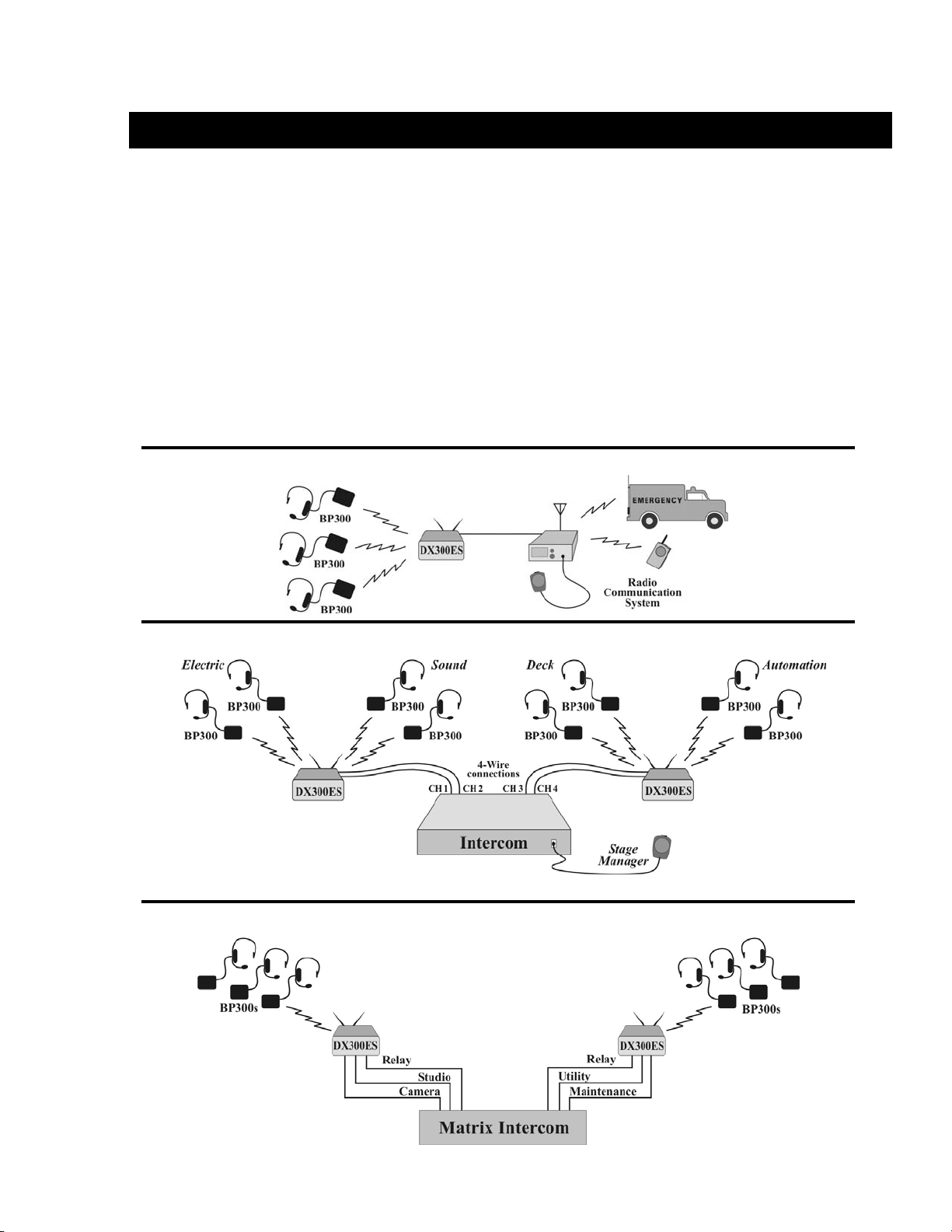
The following examples are of typical DX300ES applications.
Radio Communication Center
Theatre
Broadcasting
1
Page 5
t
SECTION 2. EQUIPMENT IDENTIFICATION
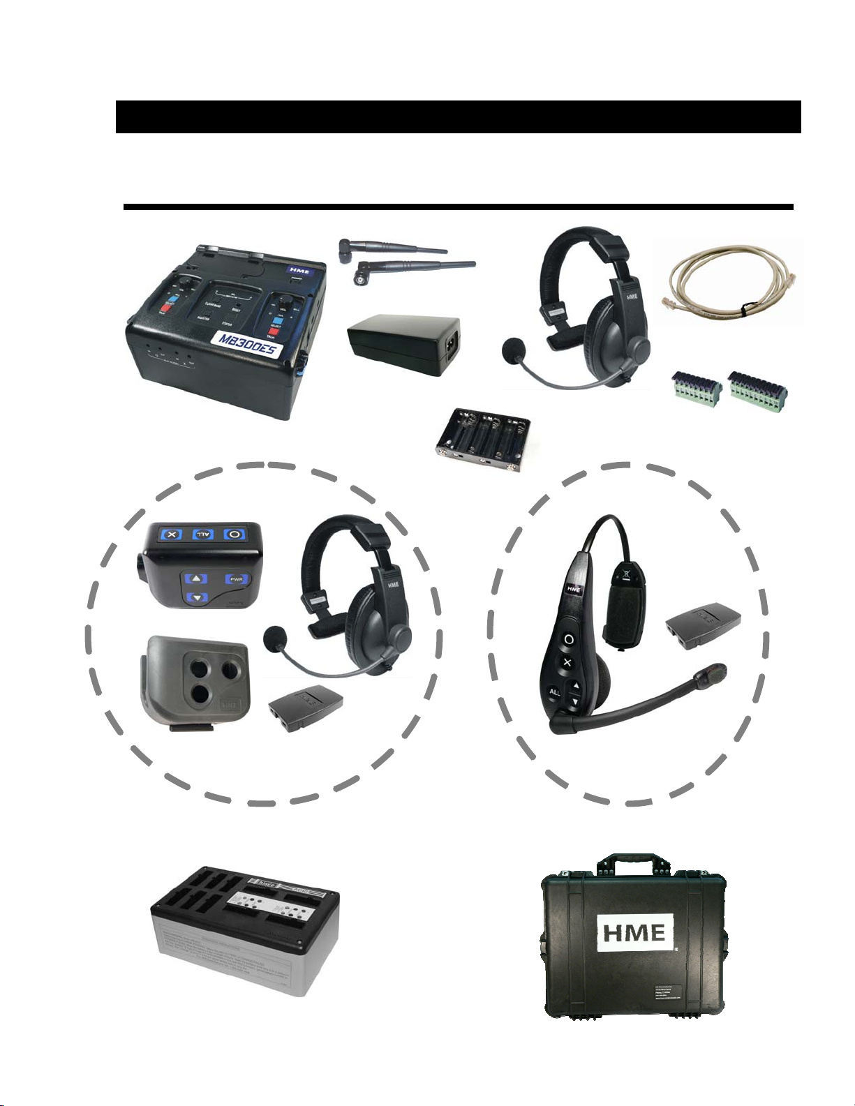
STANDARD EQUIPMENT
Base station
Beltpac with headset, pouch and battery
Antennas
Power adapter and cord
Battery sled
OR
Base station
interconnect cable
Headse
8-pin and 10-pin
spring clamp
connectors
All-in-one headset with battery
Battery charger with power supply and cord
for beltpac and all-in-one headset batteries
2
Travel case
Page 6
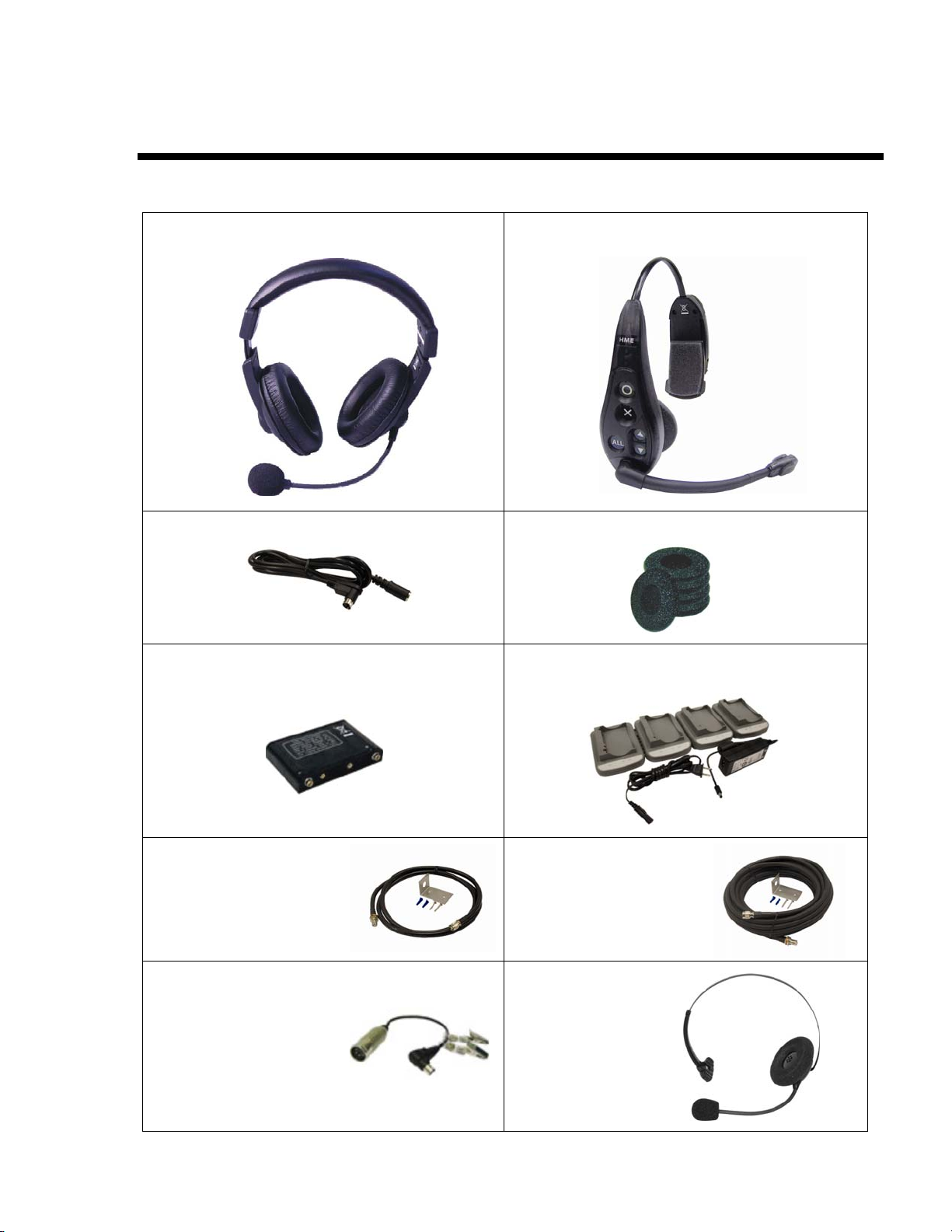
OPTIONAL EQUIPMENT
Headset with dual ear muffs
Model # HS15D
Headset extension cable, 6 ft (1.83 meter)
Rechargeable battery for base station
Model # BAT850
All-in-one headset with battery
Model # WH300
Foam earmuffs for all-in-one headset
Battery charger for use with rechargeable
base station batteries
Model # AC850
Remote antenna kit with
6 foot (1.83 meter) cable
and bracket
Adapter cable for headset with dynamic
microphone and XLR connector
Model # MD-XLR4F
MD-XLR4M
MD-XLR5F
Remote antenna kit with
30 foot (9.14 meter) cable
and bracket
Lightweight headset
Model # HS16
3
Page 7
b
b
b
t
b
(
EQUIPMENT FEATURES
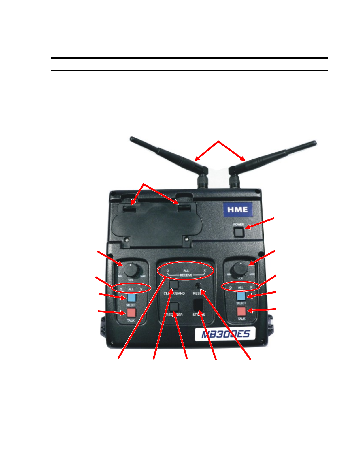
Base Station
Top Panel —
Left
headset
volume
control
Left talk
lights
Left select
utton
Left talk
button
Battery
compartment
latches
Antennas
Power
utton
Right
headse
volume
control
Right talk
lights
Right select
utton
Right talk
utton
Active Channel
lights
Clear/Band
button
Registration
button
4
Status
indicator
Reset
switch
recessed)
Page 8
b
(recessed)
b
t
r
r
p
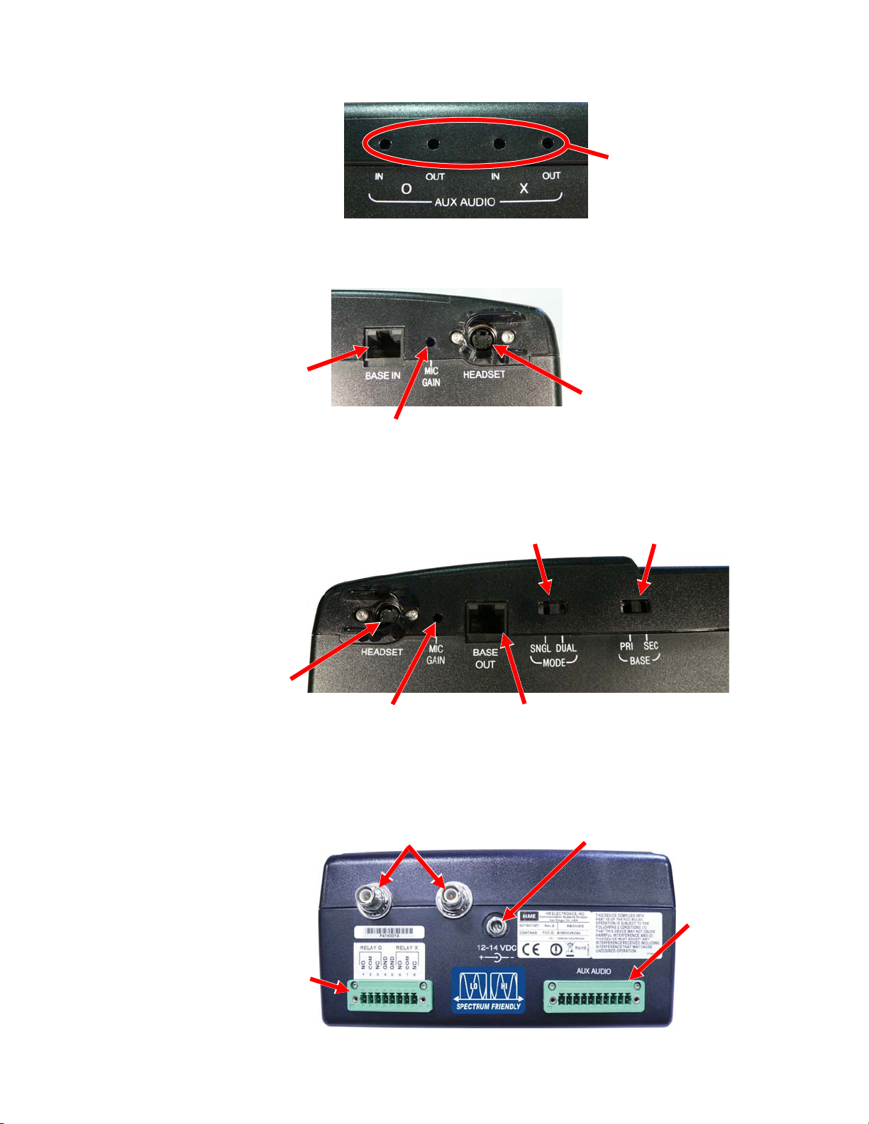
Front Panel —
Left Side Panel —
Cable “input”
from another
ase station
Right Side Panel —
connecto
Rear Panel —
8-
in connector for
equipment relay
controlled by
beltpac buttons
Right
headset
Auxiliary audio
in/out volume
adjustments
Left headset
Microphone gain
adjustment for
left headset
Single/Dual
base station
selection switch
Microphone gain
adjustment for
right headse
Antenna
connectors
Cable “output”
to another
ase station
connector
Primary/Secondary
selection switch
Power supply
connecto
base station
10-pin connector
for auxiliary
audio connection
input/output
5
Page 9
b
b
b
b
b
p
butto
t
ght
ght
boom
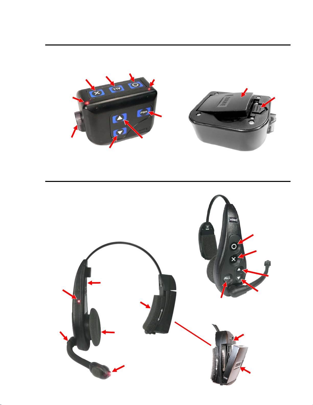
Beltpac
Power/X-channel
X-channel
utton
light
ALL
utton
O-channel
button
Power/O-channel
light
Headset
cable
connector
Volume
down button
Volume
button
u
All-In-One Headset (optional)
Power
utton
Battery
Battery
release
latch
Power/Talk
li
Microphone
Power
n
Headband
slide-to-fi
Sanitary
muff
Talk
li
O-channel
utton
X-channel
button
Volume
up button
Volume
down button
ALL
utton
Battery
release
latch
Battery
6
Page 10
SECTION 3. EQUIPMENT SETUP
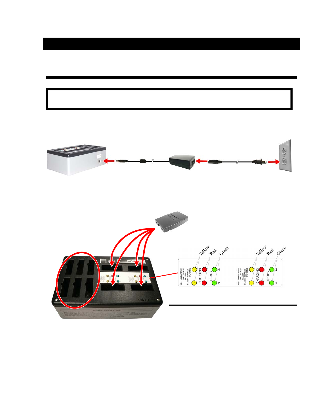
BATTERY CHARGER
NOTE: Set up the battery charger and charge all beltpac and/or all-in-one headset batteries
while you are setting up the base station.
1 Connect power supply to charger and electrical outlet
Power supply
2 Charge all beltpac batteries
Charging time is approximately 3 hours
Storage ports for
charged batteries
Power supply cord
Put up to 4 batteries
in charging ports
Status lights next to each charging port
Red light
Stays on steady while battery is charging
Green light
Goes on when battery is fully charged
Yellow light
Stays on steady when charging port is empty
Flashes if battery is too hot to charge
If on steady when battery is in charging port, charge
has failed – See instructions on side of charger
7
Page 11
connector
r
BASE STATION
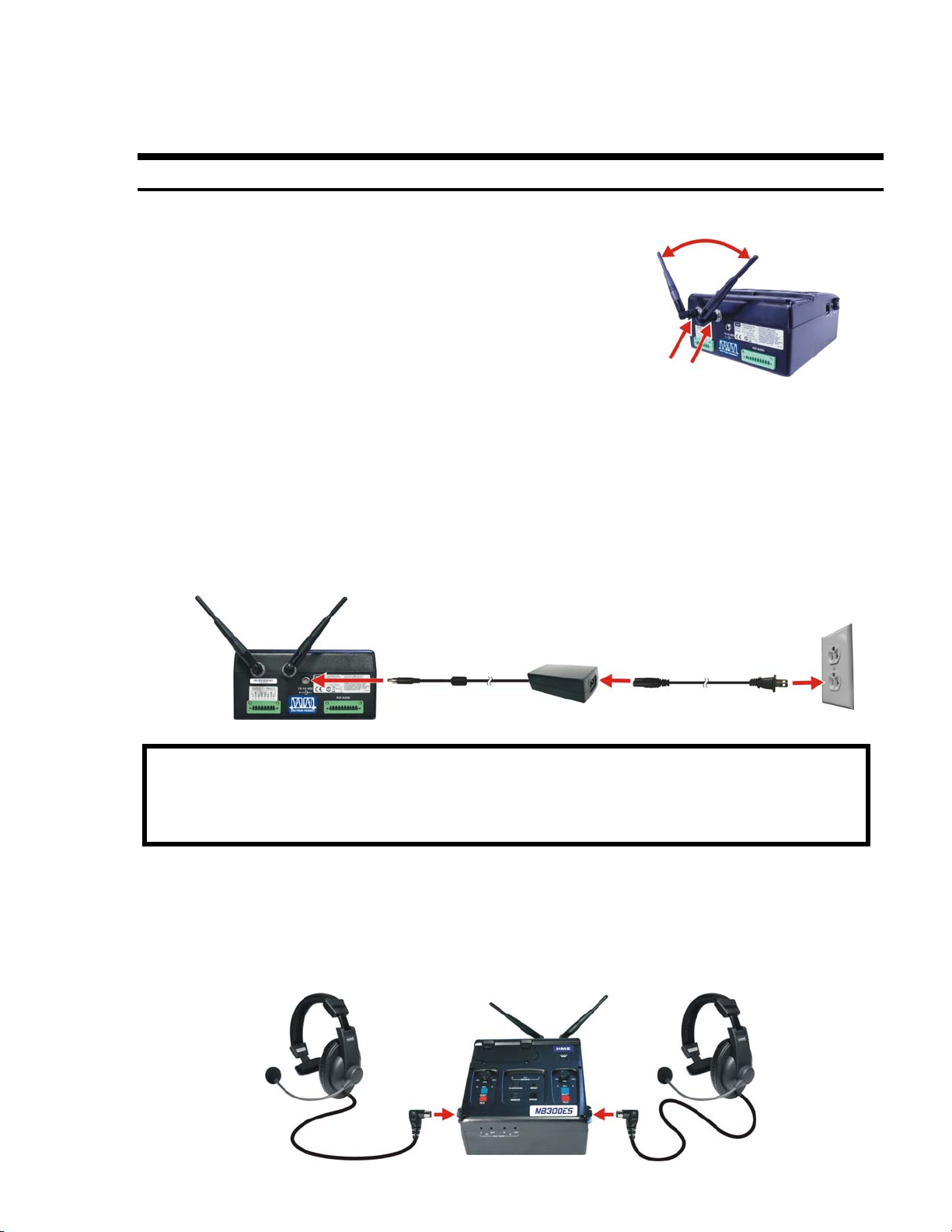
Antenna and AC Power Connections
1 Screw both antennas onto the connectors
on the back of the base station.
Tighten at 90° angle.
90° angle
Antenna
connectors
2 Set up base station where no objects are
blocking the line-of-sight from base station to the beltpacs.
If base station can not be set up wit h no o bject s in lin e-of -sigh t bet ween
it and the beltpacs, install the antennas away from the base station.
See page 17 for remote antenna installation.
3 Plug power adapter into base station and screw nut onto conn ector ,
then plug power cord into power a dap te r and e lectr ica l ou tlet .
Power
adapter
Power
cord
NOTE: A fully charged battery can be kept in the base station as a backup in case of AC
power interruption.
If AC power is unavailable, the base station can operate on battery power
(See page 9).
4 Press POWER button to turn power on.
5 Plug headsets into base station, inserting headset plugs all the way into
connectors.
Left
headset
Right
headset
connecto
8
Page 12

y
r
Optional Battery Operation of Base Station
NOTE: Always plug base station into AC power when it is available.
Turn base station off when it is not being used, to conserve battery power.
Typical base station battery life when used continuously is as follows:
BAT850 Rechargeable Battery 3 hours
Duracell Coppertop 1 hour
Energizer Lithium 6 hours
1 If you are using the battery sled, load 6 “AA” batteries into it.
2 Pull back on the battery compartment latches and lift the battery
compartment cover on the base station.
Battery
compartment
Battery
compartment
cove
Battery sled
BAT850
Batter
3 Insert the battery sled or rechargeable
BAT850 battery (optional) into the
battery compartment and close the cover.
4 If you are using the BAT850 battery, put it in the AC850
battery charger (optional) for recharging after each use.
Follow the instructions received with the charger.
Charging time is approximately 3 hours.
NOTE: When base station battery power is low, everyone connected to or registered to that
base station will hear a tone in their headset, repeating every 8 seconds and both
headset select lights will blink.
AC850 Battery Charger
9
Page 13

Spectrum Friendly™ Interference Avoidance
Interference such as popping sounds may occur when frequencies of a WiFi
system, a wireless DMX lighting system or another HME system is in use.
This interference may be avoided if these systems can be limited to one
portion of the 2.4GHz to 2.48GHz frequency band, and your base station is set
to operate in the opposite half of the band as follows:
1 Turn the base station power on.
The STATUS window will show “8” for a f ew seco nds.
After the “8” disappears, the
STATUS window will be blank.
2 Press and hold the CLEAR/BAND button and, while you are still holding
the CLEAR/BAND button, press and hold the REGISTER button.
When the STATUS window shows L, H or A,
release both buttons.
3 Press the CLEAR/BAND button repeatedly to cycle through parts of the
frequency band ― L = Low end, H = High end and A = All
Stop at the desired setting and wait until “c” appears
on the STATUS display.
NOTE: Base stations are shipped in the “A” (default) position.
“c” will appear on the STATUS display if you are re-setting the frequency band.
If you change a base station’s existing frequency band setting, you will have to
re-register all beltpacs and/or all-in-one headsets that were registered to that
base station.
10
Page 14

Multiple Base Stations
Up to 20 crewmembers can communicate in the dual-channel mode, 5 per base
station, by interconnecting base stations as described below.
Audio Connection
Connect base stations with the provided interconnect cable, from the BASE
OUT connector on one to the BASE IN connector on the other.
BASE OUT
connector
Primary base station
Interconnect cable
Secondary base station
BASE IN
connector
Dual Channel Setting
On the right side of the base stations, set the MODE switch to the DUAL or
SNGL position.
MODE switch
Right side of base station
Dual channel (DUAL) ― 3 beltpacs and/or all-in-one headsets can be used in
the hands-free mode.
Single channel (SNGL) ― When dual channel operation is not required,
4 beltpacs and/or all-in-one headsets can be used in the hands-free mode.
11
Page 15

Multiple Base Station Initialization
Multiple base stations must be “initialized” according to the following
instructions, so their frequencies will not cause interference.
After initializing each base station, register each beltpac that will be used
with that base station (See page 15).
Primary/Secondary Base Station Setting
Set the BASE switch on each base station as described below, and then
configure each base station through the initialization procedure that follows.
On the right side of each base station, set the BASE switch as follows:
1 Primary base station – Leave the BASE switch in the PRI position.
2 Secondary base stations – On each secondary base station, move the
BASE switch to the SEC position, and then press the base station
POWER switch twice to turn the power off and back on again to activate
the setting.
Right side of base station
BASE switch
3 With the primary base station
powered on first, turn on the
secondary base station.
The STATUS window will show
“8” for a few seconds, and then
a double bar.
STATUS window
with double bar
12
Page 16

4 Press the REGISTER button on the primary base station
The STATUS window will show a small “o.”
5 Press the REGISTER button on the secondary base station
to assign it a number (1, 2 or 3).
Wait until the base is initialized (approximately 10 seconds).
RECOMMENDED: If only two base stations will be used, set the secondary base
station to #2.
HINT!
beltpacs and/or all-in-one headsets, mark them with the number of the base station
they are registered to, for later identification.
Mark each base station with its assigned number, and then, when registering
6 When initialization is complete, the STATUS window will
show one bar.
7 Press the REGISTER button on the primary base station
to clear the STATUS window, or just wait and the display
will automatically go blank after timing out.
8 Repeat steps 1 – 5 to initialize up to three secondary base stations.
NOTE: When multiple HME base stations are to be used in the Spectrum Friendly™ mode,
the primary base station should always be set to the required band first.
13
Page 17

Base Station Microphone Gain Adjustment
The microphone gain adjustment allows you to adjust the level of your voice
as it is transmitted from the headsets plugged into the base station, to the
rest of the system.
Microphone gain must be adjusted for each base station headset.
1 Use a headset that is plugged into the right side of a base station, and
locate the MIC GAIN adjustment that is recessed in a hole on the right
side of the base station.
Insert small screwdriver
2 Insert a small screwdriver in the
hole and turn the adjustment
clockwise to increase or
counterclockwise to decrease
microphone gain.
Base station microphone gain adjustment
3 Speak into the headset microphone and listen to your own voice level
(sidetone) in the headset as you adjust the microphone gain.
4 Use a headset that is plugged into the left side of a base station, and
locate the MIC GAIN adjustment on the left side of the base station, and
then repeat steps 2 and 3 for the left side headset.
5 Repeat steps 1 through 4 for each base station.
NOTE: Base station microphone gain is factory set at about one-third from minimum level.
14
Page 18

BELTPACS
Beltpac Registration
NOTE: Registration of all-in-one headsets is the same as the beltpac registration described
below, except for step 2.
If you have more than one base station, you must register each beltpac and/or
all-in-one headset to the base station it will be used with.
1 Turn the base station power on, and beltpac power off.
2 Plug the headset into the beltpac and put
the headset on your head.
3 Press the REGISTER button on the base
station registration panel.
A lower case “o” will appear on the
STATUS window.
REGISTER
button
STATUS window
4 Press and hold the ALL button on the
beltpac while you press and release its
PWR (power) button.
After a brief delay, you should hear
“Registration complete” in the headset.
An ID number for this beltpac will appear
briefly on the STATUS window.
ALL button
Power button
5 Repeat steps 1 through 4 for each beltpac.
NOTE: If the registration is not successful, you will hear “Registration failed.”
If this happens, refer to TROUBLESHOOTING, on page 25.
NOTE: If you try to register more than 15 beltpacs to a base station:
An “F” (Full) will appear in the STATUS window and you will hear “Registration failed” in the
headset.
Clear all current registrations by pressing and holding the CLEAR/BAND button while you
press and release the RESET button with a pen point.
Continue holding the CLEAR/BAND button after you release the RESET button until the clear
code “c” (lower case) appears on the STATUS window.
Register all beltpacs, one at a time, including previously registered beltpacs.
15
Page 19

Beltpac or All-In-One Headset Adjustments
Sidetone Adjustment (Beltpac only, not on all-in-one headset)
When you speak into the microphone, you can hear sidetone (your own voice)
in the beltpac headset.
Sidetone can be adjusted as follows:
1 Be sure the beltpac power is on.
2 While holding down the “O” button, press the volume-up ▲ or volume-down
▼ button as many times as needed to reach an acceptable level.
You do not hear beeps except for maximum or minimum double beep.
Maximum sidetone level is recommended.
Microphone Gain Adjustment
Some people speak louder or softer than average. The microphone gain
adjustment helps to compensate for extremes in speaking level of individuals
using beltpacs or all-in-one headsets.
NOTE: The microphone gain can be monitored through sidetone, or preferably by
someone else using a beltpac or all-in-one headset, or at the base station.
1 Be sure the beltpac or all-in-one headset power is on.
2 While holding down the “X” button, press the volume-up ▲ or volume-
down ▼ button as many times as needed to reach an acceptable level.
You do not hear beeps except for maximum or minimum double beep.
Recommended microphone gain levels are:
Beltpacs – 12 clicks down from maximum
All-in-one headsets – 8 clicks down from maximum
NOTE: You will hear “Maximum” if you try to go above maximum microphone gain.
You will hear repeating beeps if you try to go below minimum microphone gain.
Microphone gain and sidetone adjustments will be saved in memory and do not
need to be reset after the unit is turned off and on.
16
Page 20

OPTIONAL REMOTE ANTENNA INSTALLATION
If it is not possible to avoid obstructions that may block signals between the
base station and the beltpacs and/or all-in-one headsets, it may be necessary
to locate the antennas away from the base station. Remote antenna kits with
either 6 foot (1.83 meter) or 30 foot (9.14 meter) cables can be used to mount
the antennas wherever necessary to alleviate this problem.
To order a remote antenna kit, see optional equipment on page 3.
Installation instructions are enclosed with the remote antenna kit.
17
Page 21

OPTIONAL AUXILIARY EQUIPMENT CONNECTION
Equipment requiring 4-Wire audio interfacing, such as audio/video recorders or
hardwired intercoms, can be connected to the 10-pin connector and plugged
into the rear panel of the base station.
Equipment requiring relay closure, such as a router or mobile radio, can be
connected to the 8-pin connec tor a nd plug ge d into r ear p ane l of th e ba se sta tion .
1 Connect the enclosed 10-pin
connector to the wires from
your auxiliary audio equipment
according to this table.
Pin Connections
1 Aux In − O
2 Aux In + O
3 Aux Out − O
4 Aux Out + O
5 Ground
6 No Connection
7 Aux In − X
8 Aux In + X
9 Aux Out − X
10 Aux Out + X
Differential pair
Differential pair
Differential pair
Differential pair
2 Connect the enclosed 8-pin connector to
the wires from equipment you would like to
control from the O, X or ALL buttons on your
beltpacs and/or all-in-one headsets
(i.e. long range radio).
3 Plug the connectors into the back panel of the base station.
8-pin and 10-pin
spring clamp connectors
4 Using a small screwdriver in the holes on the
front panel of the base station, you can adjust
the IN and OUT sound level of “O” and “X”
communication channels as needed.
18
Page 22

:
SECTION 4. EQUIPMENT OPERATION
BASIC OPERATION
Base Station
Left
headset
controls
Right
headset
controls
1 Press base station POWER button to turn on power.
2 Put left or right headset on your head.
Use headset controls on same side of base station as headset.
Headset volume
Channel indicator lights
(O, ALL or X)
Green – Listen only
Red – Talk and listen
Channel select button
(O, ALL or X)
Talk button
(Push ON – Push OFF)
3 Adjust headset volume as needed.
CAUTION
Having your headset at a high volume level for a long time can
cause hearing damage.
4 Press channel SELECT button; Green light appears above O, ALL or X
selection ― Press SELECT button again to change selection
O = O channel only ― ALL = both O & X channels ― X = X ch an ne l only
5 To talk to beltpac and/or all-in-one headset users, press and release TALK
button − Green light turns red.
Talk and listen as in normal telephone conversation.
Press and release TALK button again when you finish talking.
(You will still hear them, but they will not hear you.)
NOTE: Base station TALK buttons do not activate relay closures.
6 To turn base station off, press and hold POWER button until the lights go off.
19
Page 23

y
Beltpac / All-In-One Headset
The O, X and ALL button functions described below are for operation in the
standard default mode. The buttons can also be set to function in other
modes. See page 22 for operating mode setups.
1 Be sure fully charged battery is in the unit.
2 If using beltpac —
Plug headset into beltpac and put headset on your head.
Slide beltpac into pouch and clip it on your belt.
3 Press and release PWR (power) button to turn unit on.
Beltpac power button
All-in-one headset power button
(above earpiece on inside surface)
4 Press and release O button to communicate with O channel users, or
press the X button to communicate with X channel users.
Speak to O channel users
and activate O rela
Speak to X channel users
and activate X relay
5 To communicate with both O and X channel users, press and hold ALL
button while talking.
Speak to ALL O and X channel users
and activate both O and X relays
6 Adjust headset volume as needed.
CAUTION:
Increase volume Decrease volume
Having your headset at a high volume level for a long time can
cause hearing damage.
7 To turn unit off, press and hold power button for about 2 seconds until
you hear “Power off.”
20
Page 24

Changing Batteries
Beltpac batteries typically provide 20 hours of continuous use in listen mode.
If you hear “Change battery” in your headset
―
1 If using beltpac, remove it from its pouch.
2 On beltpac or all-in-one headset, slide battery release latch
in direction of arrow.
3 Lift battery out of beltpac or all-in-one headset.
4 Place battery in battery charger port for recharging.
5 Install fully charged battery in beltpac or all-in-one headset.
6 If using beltpac, put it back in its pouch.
Battery
release
latch
Beltpac
Battery
Battery
release
latch
All-in-one headset
Battery
21
Page 25

Operating Mode Setup
Set up beltpacs and/or all-in-one headsets to operate in the desired mode by
pressing and holding the button combinations shown below when you press
the PWR (power) button to turn the unit on.
Mode Button Combination Button Functions
X = X-channel only
(default) Hold X + O + ALL and press PWR
O = O-channel only
ALL = both X and O channels
O-channel only Hold O and press PWR
O-channel + ALL Hold O + ALL and press PWR
X-channel only Hold X and press PWR
X-channel + ALL Hold X + ALL and press PWR
O-channel + X-channel only Hold X + O and press PWR
Latching
(Hands-Free, Full-Duplex)
Push-To-Talk (PTT) Hold ALL + ▼ and press PWR
Hold ALL + ▲ and press PWR
X & O both = O-channel
ALL has no function
X & O both = O-channel
ALL = both X and O channels
X & O both = X-channel
ALL has no function
X & O both = X-channel
ALL = both X and O channels
X = X-channel only
O = O-channel only
ALL has no function
X & O will latch on when pressed and
released, for a normal two-way
conversation
X, O & ALL must be pressed and held
while you talk, and released to listen
NOTE: Mode settings will be stored, so your beltpacs and/or all-in-one headsets will have
the same mode settings after you turn them off and back on.
NOTE: ALL does not latch on, and must be held down to hear both O and X.
22
Page 26

RADIO APPLICATIONS
Emergency Services
Operating Scenario
● All crewmembers will hear both the Crew Channel and Radio Channel
simultaneously.
● All crewmembers have the ability to talk to other crewmembers in either
Latching (hands-free) or PTT (push-to-talk) modes, using either the O or X
buttons.
● All crewmembers have the ability to talk to the radio channel in a PTT
mode, using the ALL button.
Beltpac Configuration
● Set for Latching mode with the O and ALL buttons enabled.
● The X button will work as a second O button.
NOTE: Application shown is for radio equipment requiring Ext MIC PTT connection to be
pulled low to key radio transmitter.
23
Page 27

Production Crew with Separate Radio Channel
Operating Scenario
● Production Manager will monitor Radio Channel and Production Crew
Channel simultaneously, hands free. Production Manager can selectively
talk to Radio channel or Production Crew Channel.
● Production Crew members will hear and talk to Production crew members
only.
● Radio Crew members will hear and talk to radio Crew members only.
Beltpac Configuration
● Production Manager Beltpac set for X and O and ALL (monitor on O).
● Crew Beltpac set for X only.
NOTE: Application shown is for radio equipment requiring Ext MIC PTT connection to be
pulled low to key radio transmitter.
24
Page 28

SECTION 5. TROUBLESHOOTING
If you are unable to correct any of the problems described below or if your problem is not
covered, call 1-800-848-4468 for assistance.
Power light on base station does not come on when power button is pressed.
Be sure the power supply is properly connected to the base station, and the power cord is
properly connected to the power supply and electrical outlet.
If operating on battery power, be sure the battery is charged and in the battery compartment
with the cover securely closed.
Beltpac or all-in-one headset power lights do not turn green and you hear “out of range.”
Be sure the base station power is on.
Turn beltpac or all-in-one headset power on and off.
Beltpac or all-in-one headset may be too far from the base station.
When trying to register a beltpac or all-in-one headset, you hear “registration failed.”
Press the RESET button on the base station with the point of a pen.
The STATUS window will show “8” and then become blank.
Try again to register the beltpac or all-in-one headset.
If registration fails again, call your dealer for assistance.
No one can hear me when I talk.
On the beltpac or all-in-one headset, be sure you are pressing the X, O or ALL button.
On the base station, be sure you have selected the correct channel, and you are pressing the
TALK button.
Be sure the headset plug is properly connected to the beltpac or base station.
With more than one base station, one base station operator can not hear O or ALL
transmission from another base, or another base station operator can not hear X or
ALL transmission from another base.
Be sure interface cable is properly connected from BASE OUT on the primary base station to
BASE IN on the secondary base station, and so on.
If problem is not resolved, try using a different interface cable.
No or low auxiliary audio sound.
Check wiring from auxiliary equipment to AUX AUDIO connector on back of the base station.
Turn AUX AUDIO adjustments on front of base station with a small standard (flat) screw
driver, clockwise to increase level and counterclockwise to decrease level.
25
Page 29

Beltpac or all-in-one headset users can not hear or talk to base station operators who
are using headsets.
Be sure base station headsets are fully plugged into the base station headset connectors.
Be sure the appropriate SELECT lights are red (O, X or ALL) when base station operators are
talking.
Be sure everyone is talking or listening on the right channel (O, X or ALL).
Beltpac range is bad.
Be sure antennas are properly connected and tightened on base station.
Be sure base station is positioned where there are no physical obstructions blocking line-of-
sight from the base station to beltpacs or all-in-one headsets.
Beeping is heard in base station headset and SELECT lights are blinking.
Base station is operating on battery power and battery is low.
Not all beltpac buttons are working.
Button functions may have been changed to work in the desired operating mode
(See page 22).
There is interference from a cordless telephone.
A 2400MHz cordless telephone nearby may cause interference, which may be corrected by
doing the following:
Change frequencies on the phone.
Move the phone as far as possible from the base station.
Use another type phone.
(If your base station does not have a battery backup)
In the event of an electrical power outage — such as from lightning or a power generator
failure, if you experience problems with your DX300ES equipment after the power comes on
again, unplug the AC power supply from its electrical outlet and wait 15 seconds, then plug it
back in.
26
Page 30

FREQUENTLY ASKED QUESTIONS
Are the battery charger and base station power supplies interchangeable?
Yes.
What is the maximum recommended number of base stations that can be linked
together with interconnect cables?
Four.
Does linking the base stations automatically prevent them from interfering with each
other?
No, all bases that are linked together must be initialized or set to the high or low portion of the
frequency band to prevent them from interfering with each other’s frequencies.
If the primary base station is turned off just momentarily (before the secondary base(s)
have a chance to start working independently), will the secondary base(s) automatically
re-initialize to the primary?
Yes, the secondary base(s) will re-establish communication without being initialized again.
Will a secondary base station continue to operate if its primary is turned off for a period
of time?
Yes & No. Secondary base stations will initially stop operating when the primary base is
turned off, but will resume operation independently after about 40 seconds.
Three bars will appear in its STATUS display, and its beltpacs will still be able to communicate.
If the primary base station is turned back on, the secondary base must be turned off and on
again to re-establish proper initialization.
Can I use more than three beltpacs on a single base station in dual channel mode?
Yes, but only three users will be able to transmit at the same time.
Up to 15 beltpacs can be registered to a single base station.
Beltpacs and all-in-one headsets should be placed in push-to-talk (PTT) mode when more than
3 beltpacs or all-in-one headsets are used (See page 22).
What should I do if my carrying case and equipment get wet?
Dry them out thoroughly before further use.
Be sure all equipment is dry before using it again.
CAUTION
: Plugging wet electrical equipment into an AC power outlet is dangerous!
27
Page 31

SECTION 6. TECHNICAL DATA
EQUIPMENT SPECIFICATIONS
Base Station
GENERAL ⎯
Frequency Range: All, 2400 – 2483.5 MHz
Low, 2401.92 to 2439.94 MHz
High, 2443.39 to 2481.41 MHz
Frequency Response: 200 Hz to 3.5 kHz
Power Requirements: 100-240VAC, 50-60Hz
12-14VDC or six AA batteries (NiMH optional)
Temperature Range: 32-122°F (0-50°C)
Size: 8” x 8” x 3.5” (20.32 x 20.32 x 8.89 cm)
Weight: 2.75 lb with battery (1.25 kg)
# of Beltpacs per Base: 15 can be registered; any 4 can have simultaneous full-duplex
communication at one time (in single channel mode)
8-Wire I/O: RJ45, 600Ω balanced out, high impedance in
Auxiliary Audio: 10-Ckt Phoenix connector, 600Ω balanced out, high impedance in,
level adjustable
Headset Connectors: 4-pin mini-DIN
Electret microphone: 45 KΩ
Headset Output: 200mW into 32Ω
Top Panel Controls
and Indicators: Power button
Left and Right headset controls
Rotary knobs for headset volume (VOL) adjustment
Headset SELECT buttons (O, X or ALL)
Headset TALK buttons
Registration controls
CLEAR/BAND button
REGISTER button
RESET switch (recessed)
STATUS indicator
Headset transmit dual-color LEDs, left and right (red/green) – O, X, ALL
RECEIVE LEDs (green) – O, X, ALL
Front Panel: Auxiliary input and output level adjustments
Left Panel: 8-wire audio port
Microphone gain adjustment
Left headset connector
Right Panel: Right headset connector
Microphone gain adjustment
8-wire audio port
Single/Dual selection switch
Primary/Secondary selection switch
Rear Panel: Auxiliary input and output connectors
Antenna connectors
Antenna Type: External ½ -wave dipole (R-TNC connector)
RX/TX horizontal/vertical diversity
System Distortion: <2%
Communication Security: 64-bit encryption dual-slot diversity
28
Page 32

TRANSMITTER ⎯
Type: Frequency hopping, spread spectrum
Transmit Power: 100mW burst
Modulation Type: Gaussian filtered FSK, TDMA
Frequency Stability: 13 ppm
Harmonics/Spurious: Exceeds FCC and ETSI specifications over temperature
RECEIVER ⎯
Type: Frequency hopping, spread spectrum
RF Sensitivity: <–90dBm w 10
Frequency Stability: 13 ppm
Distortion: <2%
-3
BER
Beltpac
Frequency Range: 2400 MHz – 2483.5 MHz
Antenna: Internal, horizontal/vertical diversity
Frequency Response: 200 Hz to 3.5 kHz
Transmit Power: 100mW burst
RF Sensitivity: <–90dBm w 10
Battery Requirements: 3.6V lithium ion, rechargeable
Battery Life: Hands-free – up to 14 hours
PTT – up to 20 hours
Temperature Range: 32-122°F (0-50°C)
Weight: 7.4 oz (.21 kg) with battery and pouch
Headset Connector: 4-pin, mini-DIN
Microphone: Electret
Headset Output: 160mW into 32Ω
Controls: Power PWR, Volume-up S, Volume-down T, O, X, ALL
Indicators: Dual-color LED (red/green)
-3
BER
All-In-One Headset
Frequency Range: 2400 MHz – 2483.5 MHz
Antenna: Internal
Frequency Response: 200 Hz to 3.5 kHz
Transmit Power: 100mW burst
RF Sensitivity: <–90dBm w 10
Battery Requirements: 3.6V lithium ion, rechargeable
Battery Life: Hands-free – up to 14 hours
PTT – up to 20 hours
Temperature Range: 32-122°F (0-50°C)
Weight: 5.7 oz (.16 kg) with battery
Microphone: Electret
Headset Output: 160mW into 32Ω
Controls: Power, Volume-up S, Volume-down T, O, X, ALL
Indicators: Transmit LED (red in “X” channel / green in “O” channel)
Power LED (red/green)
-3
BER
29
Page 33

BASE STATION
BLOCK DIAGRAM
30
Page 34

SECTION 7. INDEX
Base station
audio connection (multiple base stations) ...............................................................................11
features......................................................................................................................................4
interference avoidance, Spectrum Friendly™ .........................................................................10
microphone gain adjustment ...................................................................................................14
operation..................................................................................................................................19
primary/secondary setting (multiple base stations) .................................................................12
setup (multiple base stations)..................................................................................................11
setup (single base station).........................................................................................................8
setup for battery operation.........................................................................................................9
single/dual channel setting ......................................................................................................11
specifications...........................................................................................................................28
Base station block diagram.........................................................................................................30
Battery charger setup....................................................................................................................7
Beltpac
changing batteries ...................................................................................................................21
features......................................................................................................................................6
microphone gain adjustment ...................................................................................................16
operating mode setup..............................................................................................................22
operation..................................................................................................................................20
registration...............................................................................................................................15
side tone adjustment ...............................................................................................................16
specifications...........................................................................................................................29
Equipment
optional......................................................................................................................................3
standard.....................................................................................................................................2
Headset, all-in-one
changing batteries ...................................................................................................................21
features......................................................................................................................................6
microphone gain adjustment ...................................................................................................16
operating mode setup..............................................................................................................22
operation..................................................................................................................................20
registration...............................................................................................................................15
specifications...........................................................................................................................29
Optional equipment installation
auxiliary equipment connection ...............................................................................................18
remote antennas......................................................................................................................17
Troubleshooting ..........................................................................................................................25
Frequently Asked Questions ...................................................................................................27
31
 Loading...