

Page 1
DX100
Wireless Intercom
HME# 400G626
Rev B 1/14/10
Operating Instructions
Page 2

Page 3

Table of Contents
SECTION 1. INTRODUCTION.......................................................................................................................1
EQUIPMENT IDENTIFICATION.......................................................................................................................2
MAIN EQUIPMENT FEATURES.......................................................................................................................3
Base Station Features ........................................................................................................................................ 3
Beltpac Features ................................................................................................................................................ 3
WH200 Headset Features..................................................................................................................................4
Speaker Station Features ................................................................................................................................... 4
SECTION 2. EQUIPMENT SETUP................................................................................................................. 5
BATTERY CHARGER SETUP ...........................................................................................................................5
Connect AC Power Supply................................................................................................................................5
Charge Batteries ................................................................................................................................................ 5
BASE STATION SETUP...................................................................................................................................... 6
Antenna and Power Setups................................................................................................................................6
Interference Avoidance......................................................................................................................................8
Multiple Base Stations....................................................................................................................................... 9
Primary and Secondary Base Station Settings...................................................................................................9
Base Station Initialization................................................................................................................................10
BELTPAC / WH200 HEADSET / SPEAKER STATION SETUP AND REGISTRATION............................12
Set Up Beltpacs ............................................................................................................................................... 12
Register Beltpacs.............................................................................................................................................12
Set Up WH200 Headsets................................................................................................................................. 14
Register WH200 Headsets...............................................................................................................................14
Set Up Speaker Station....................................................................................................................................16
Register Speaker Station.................................................................................................................................. 18
SECTION 3. EQUIPMENT OPERATION...................................................................................................20
BASE STATION OPERATION ......................................................................................................................... 20
Controls and Indicators....................................................................................................................................20
Low Battery Indicator......................................................................................................................................20
BELTPAC OPERATION.................................................................................................................................... 21
WH200 HEADSET OPERATION......................................................................................................................23
SPEAKER STATION OPERATION.................................................................................................................. 25
SECTION 4. TROUBLESHOOTING............................................................................................................28
SECTION 5. TECHNICAL DATA................................................................................................................. 29
EQUIPMENT SPECIFICATIONS ..................................................................................................................... 29
Base Station.....................................................................................................................................................29
Beltpac............................................................................................................................................................. 30
WH200 Headset............................................................................................................................................... 30
Speaker Station................................................................................................................................................30
Illustrations in this publication are approximate representations of the actual
equipment, and may not be exactly as the equipment appears.
HM Electronics, Inc. is not responsible for equipment malfunctions due to
erroneous translation of its publications fr om thei r original English version.
The HME logo and product names are registered trademarks of HM Electronics, Inc. All rights reserved.
© 2010 HM Electronics, Inc.
Page 4

INFORMATION TO USER
This device complies with Part 15 of the FCC Rules. Operation is subject to the following two conditions: (1) This device may
not cause harmful interference, and (2) This device must accept any interference received, including interference that may cause
undesired operation.
This equipment has been tested and found to comply with the limits for Class B Digital Device, pursuant to Part 15
of the FCC Rules. These limits are designed to provide reasonable protection against harmful interference in a
residential installation. This equipment generates and can radiate radio frequency energy and, if not installed and
used in accordance with the instructions, may cause harmful interference to radio communications. However, there
is no guarantee that interference will not occur in a particular installation. If this equipment does cause harmful
interference to radio or television reception, which can be determined by turning the equipment off and on, the user is
encouraged to try to correct the interference by one or more of the following measures.
• Reorient or relocate the receiving antenna
• Increase the separation between the equipment and receiver
• Connect the equipment into an outlet on a circuit different from that to which the receiver is connected
• Consult the dealer or an experienced radio/TV technician for help
Any changes or modifications not expressly approved by the party responsible for compliance could void the user’s
authority to operate the equipment.
MANDATORY SAFETY INSTRUCTIONS
FOR INSTALLERS AND USERS
Use only manufacturer or dealer supplied antennas.
The Federal Communications Commission has adopted a safety standard for human exposure to RF (Radio Frequency)
energy, which is below the OSHA (Occupational Safety and Health Act) limits. These instructions also meet Industry
Canada RSS-GEN 7.14.
The term “IC:” before the certification number signifies that the Industry Canada technical specifications were met.
Base Station Antenna minimum safe distance: 7.9 inches (20 cm) at 100% duty cycle.
Base Station Antenna gain: This device has been designed to operate with an antenna having a maximum gain of up to
2dBi. The required antenna impedance is 50 Ohms.
Antenna mounting: The antenna(s) used for the base transmitter must be installed to provide a separation distance of at
least 7.9 inches (20 cm) from all persons and must not be co-located or operating in conjunction with any other antenna or
transmitter.
Antenna substitution: Do not substitute any antenna for the one supplied by the manufacturer or radio dealer. You may
be exposing person or persons to excess radio frequency radiation. You may contact your radio dealer or the manufacturer
for further instructions.
WARNING: Maintain a separation distance from the base station transmit antenna to a person(s) of at least 7.9 inches (20 cm)
at 100% duty cycle.
You, as the qualified end-user of this radio device must control the exposure conditions of bystanders to ensure the
minimum separation distance (above) is maintained between the antenna and nearby persons for satisfying RF exposure
compliance. The operation of this transmitter must satisfy the requirements of Occupational/Controlled Exposure
Environment, for work-related use. Transmit only when person(s) are at least the minimum distance from the properly
installed, externally mounted antenna.
Hereby, HM Electronics, Inc. declares that the DX100 is in compliance with the essential requirements and other relevant
provisions of R&TTE Directive 1999/5/EC.
This product operates in the 2400 to 2483.5 MHz frequency range. The use of this frequency range is not yet
harmonized between all countries. Some countries may restrict the use of a portion of this band or impose other
restriction relating to power level or use. You should contact your Spectrum authority to determine possible restrictions.
Page 5
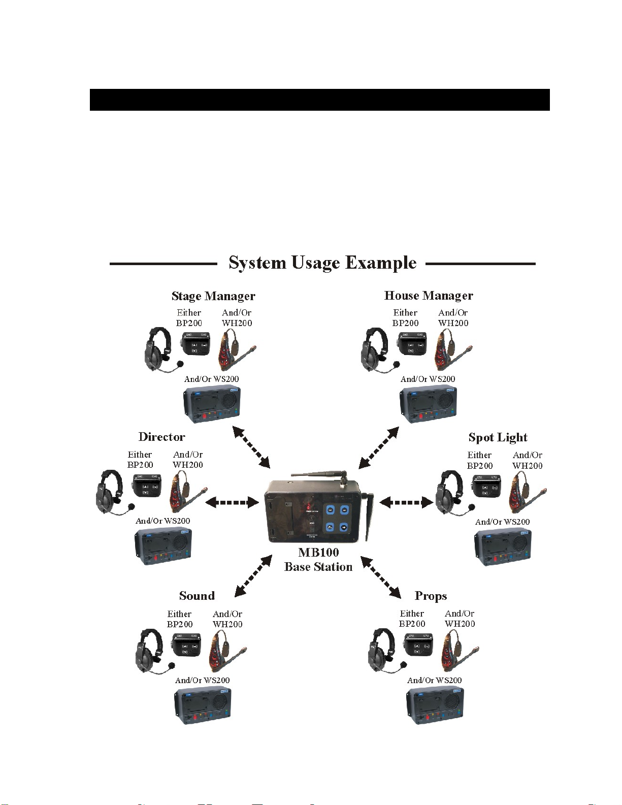
SECTION 1. INTRODUCTION
The DX100 provides private, secure communication. Each base station can have up to a total of fifteen BP200
Beltpacs, WH200 All-in-one Wireless Headsets and/or WS200 Wireless Speaker Stations “registered” to it. All
Beltpacs or all WH200 Headsets, or a combination of Beltpacs, Headsets and/or Speaker Stations can be used.
Four of the fifteen Beltpacs, Headsets and/or Speaker Stations can transmit at the same time.
Beltpacs/Headsets/Speaker Stations can be used either in the Push-To-Talk (PTT) or Hands-Free (HF) mode.
The base station operator can stop any Beltpac/Headset/Speaker Station from transmitting.
The MB100 Base Station and WS200 Speaker Station can be operated using standard AC electricity, an external
DC power source or six AA batteries. A power supply, cable and a battery sled are included with the base station.
This is an example of a typical theatrical application. A variety of other uses for the DX100 are possible.
1
Page 6

EQUIPMENT IDENTIFICATION
t
The following equipment is standard with the DX100 Wireless Intercom System.
As you unpack the equipment, check the enclosed shipping documents to be sure you received all items listed.
MB100 Base Station
WH200 All-in-one
AC40A
Battery Charger
Wireless Speaker Station
115/230 Volt AC Power Supply
with Power Cord for WS200
WS200
Base Station Antennas
(2 per Base Station)
Battery
WS200 Battery Sled
(1 per Base Station, with Power Cord)
(1 per AC40A Battery Charger, with Power Cord)
BP200 Beltpac
Beltpac Pouch
HS4-3 Earpiece & Lapel Microphone
HS15 Single-Muff Headset
HS15D Dual-Muff Headset
HS16 Lightweight Headset
HSI6000 Headset Adapter
XLR Headset Adapters:
MD-XLR4M Mini-DIN to 4-Pin Male
MD-XLR4F Mini-DIN to 4-Pin Female
MD-XLR5F Mini-DIN to 5-Pin Female
BAT850 Rechargeable Battery for WS200
AC850 Battery Charger for WS200
Base Station Battery Sled
115/230 Volt AC Power Supply
HS15 Headse
OPTIONAL EQUIPMENT
2
Page 7
MAIN EQUIPMENT FEATURES
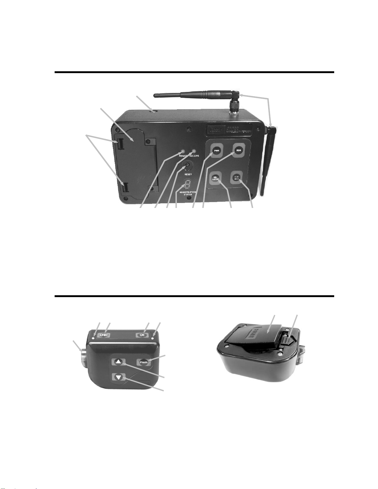
Base Station Features
10
11
12
1.
POWER indicator light
. RECEIVE indicator light
2
3. RESET button
4. REGISTRATION STATU
5. PWR (Power) b
6. REG (Registration) button
utton
1 2 3 4 5 6 7 8
7. UN-LATCH button
8. CLR/BND (Clear/Band) button
9. Antennas
S display
10. Power connector
partment cover
11. Battery com
12. Battery compartm
9
ent cover release latches
eltpac Features
B
1
. Headset cable connector
1
. Beltpac power and transmit lig hts
2
3. ISO (Isolate) button
4. IC (Intercom) button
5. PWR (Power) button
2 3 4 2
8 9
5
6
7
6. Volume-up S button
7. Volume-down T button
8. Battery
9. Battery release latch
3
Page 8
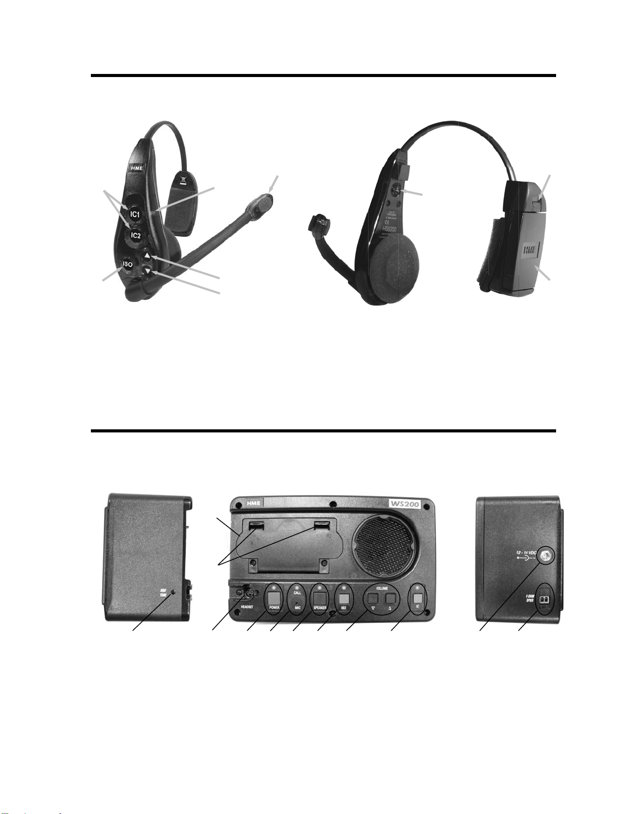
H Features W 200 Headset
3
4
Power light
1.
Transmit light
2.
3. IC1 & IC2 (Int
4. ISO (Isolate) b
1
5
6
ercom) buttons
utton
2
5. Volume-up S button
6. Volume-down T button
7. Power button
8. Battery release latch
9. Battery
7
8
9
peaker Station Features
S
Left side panel Front panel Right side panel
2
3
1
1. SIDE TONE adjustme (recessed)
Battery compartment cover
2.
3. Battery compartment cover release latches
4. HEADSET connector
5. POWER button and light
6. icrophone) CALL light and MIC (m
4
nt
5
6
8 10 9 12 11
7
7. SPEAKER t
8. ISO (Isolate) button and light
9. VOLUME down T and up S buttons
10. IC (Intercom) button and light
11. Power supply cable connector
12. External speaker connector
button and ligh
4
Page 9
ge p
ging port
ging p
SECTION 2. EQUIPM
r
r
t
ENT SETUP
BATTERY CHARGER SETUP
IMPORTANT! – Before installing the system, connect the AC power supply to the AC40A Battery Charger
and plug it into an electrical outlet. Charge all the batteries while the other equipment is being installed.
Charging time is about 2.5 hours.
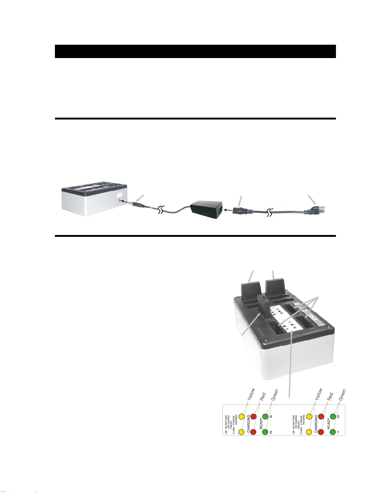
Connect AC Power Supply
• Attach the AC power supply cable connector to the screw connector on the battery charger.
• Plug the power cord connector into the AC power supply.
• Plug the power cord into an electrical outlet.
The red lights on the charger will come on and go off, and then the yellow lights will come on and stay on.
To electrical
outle
AC40A Battery Charger
Power supply
cable connecto
AC power supply Power cord
Power cord
connecto
Charge Batteries
Up to four batteries can be charged in the battery charger at
the same time. The battery status lights next to each
charging port are explained below. Up to six fully charged
batteries can be stored in the battery storage ports.
• Insert a battery in each of four charging ports until it
clicks in place.
• A yellow light next to each charging port stays on while
the port is empty. When a battery is in a charging port, a
flashing yellow light next to it indicates CHARGE
PENDING, which means the battery is too hot . Adjust
the room temperature or move the charger to a cooler
area. When a battery is in a charging port, a yellow light
on steady next to it means CHARGE FAILED.
If this happens, follow the instructions on the side of
battery charger.
• A red CHARGING light next to a battery port stays on
while a battery in the port is charging.
A green READY light next to a battery port goes on
when a battery in the port is fully charged.
Store fully charged batteries in storage ports.
NOTE: The storage ports neither charge nor maintain the
batteries. They simply provide a place to store the
charged batteries until they are needed.
Batteries should not be left in charge ports after being fully
charged. If a battery is left in a charge port for more than
three weeks, the yellow indicator may light up. In this case, it does not indicate a faulty battery.
Charged batteries
in stora
Battery in
char
orts
char
Empty
orts
5
Page 10
BASE STATI
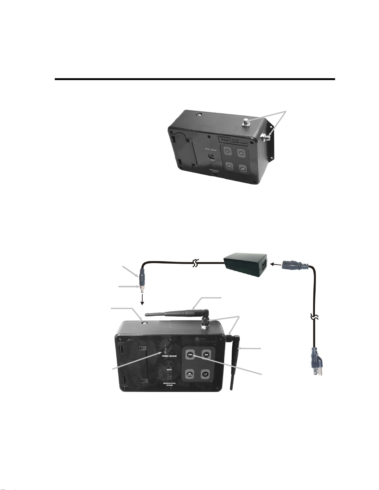
Locate the two base station antennas and the AC power adapter and power cord received with the base station,
and connect them to the base station as described below.
ON SETUP
Antenna and Power Setups
Step 1. Connect the two enclosed
antennas to the antenna
connectors on the top and right
side of the base stati on, sho wn to
the right. Position the antennas
at right angles to each other.
The illustration belo w shows one
possible arrangement. Turn the
sleeve on each of the antenna
connectors clockwise to tighten
the antennas securely in position.
Step 2. Note which of the following applies to you.
• If using the D
cable into the p
clockwise to secure it to the base station. Plug the large female connector at one end of the AC
power cord in
Power supply
cable connector
Sleeve
Power
connector
X100 with AC power wer supply
ower connector on to ble connector
to the power supply. Plug the other end of the AC power cord into an electrical outlet.
Antenna
connectors
⎯ Plug the connector at the end of the AC po
p of the base station. Turn the sleeve on the ca
le Power supply cab
AC power supply
Antenna
Sleeves
Powe
cord
r
POWER
light
Antenna
PWR button
6
Page 11
p
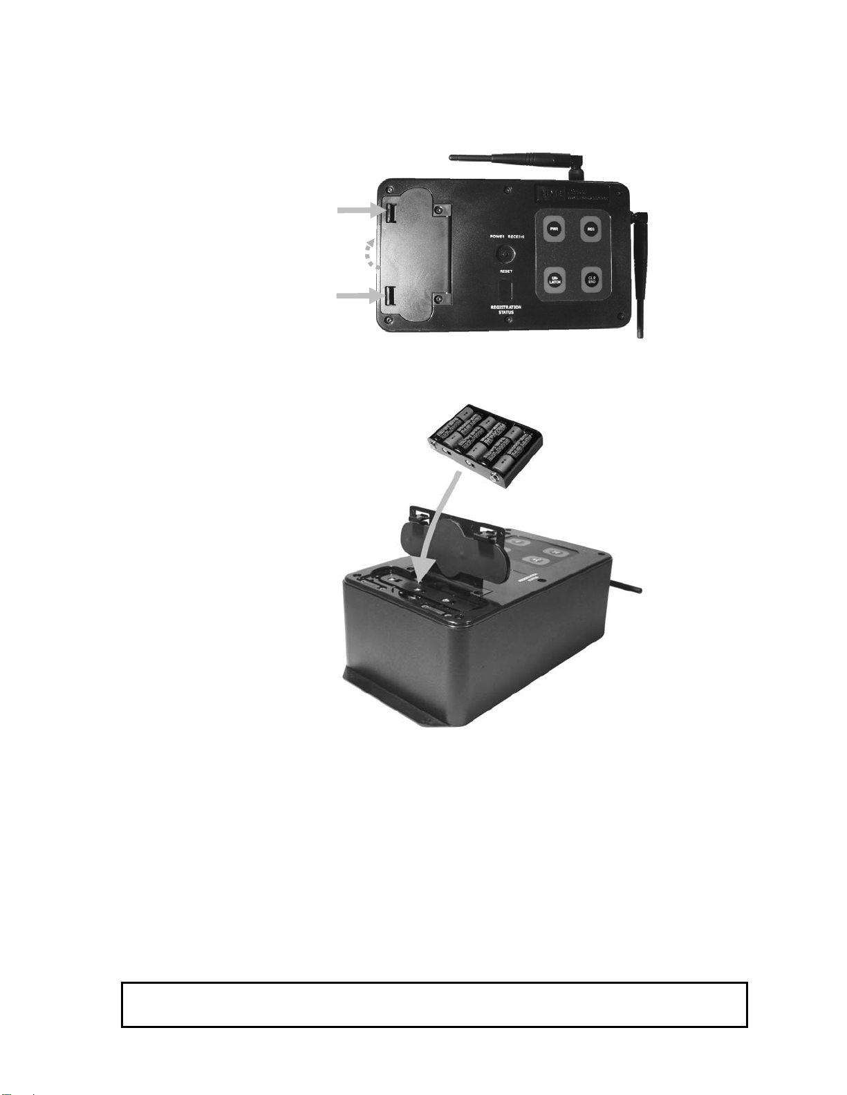
• If using the DX100 with batter
y power ⎯ Press in and up on the two battery cover release
latches to lift the cover and open the battery compartment.
Battery cover
release latches
(Push latches i
n
direction of arrows
and fli
lid up.)
Insert six AA batteries into
sled in the battery compartm
th e
e battery sled, in the positions shown inside the sled, and install th
ent as shown below. An HME BAT850 Rechargeable NiMH Battery
may be used instead.
Battery sled
with batteries
Close the battery compartment by pressing its cover down until both latches snap in place.
NOTE: Pressing down on the cover next to both of the latches at the same time
will assure its
proper closing.
• If using the DX100 with an external DC power source ⎯ We recommend that you purchase a
power co
w apter plug tip PN 273-1717. Follow the manufacturer’s instruc t the external
rd such as the Radio Shack 12VDC, 5A cigarette lighter power adapter, PN 270-1558
ith ad tions to connec
DC power source to the power connector on top of the DX100. Any power supply used with the
DX100 should be rated at least 12VDC, 500mA.
NOTE: Having a fully charged (or new) battery in its battery compartment when operating the DX100 with AC
or external DC power can prevent interruption of communication during a power outage, as the base
station will automatically switch to battery power.
If only one base station will be used, skip pages 8 – 11 and go on to page 12.
If more than one base station will be used, continue with all the instructions on the following pages.
7
Page 12

Interf e
er nce Avoidance
Interference, ur whenever other equipment such as
WI-FI systems, wireless DMX systems, other HME Base Stations, etc. use the same frequency band. If these
systems can be limited to one portion of the band, then the DX100 can be set to the opposite half of the 2.4 GHz
to 2.48 GHz band. To avoid this type of interference, select the upper part of the frequency range on one Base
Station (or more), and the lower part of the frequency range on the other(s) as follows:
• Turn on the Bas
An “8” will a RATION STATUS display for a few seconds.
• After the
display i
base), press and hol
are still holding the CLR/BND button, press and hold the REG
button and wait until a L, H or A appears, and then release both
buttons.
• Press the CLR/BND button to cycle through parts of the
frequency band; L = Low end, H = High end and A = All.
• Wait until “c” appears on the display.
NOTE: Ba in the A (default) position.
which may be heard in a headset as popping sounds, may occ
e Station power.
ppear on the REGIST
“8” disappears and the REGISTRATION STATUS
s blank (primary base) or shows a double bar (secondary
d the CLR/BND button and then, while you
REGISTRATION
STATUS display
se stations are shipped
“c e REGISTRATION STATUS display if you are setting the frequency
” will only appear on th
ban
d the first time, or you are changing the setting.
If y
ou stop at L, H or A that was already set, an “8” will appear for a few seconds and the
RE
GISTRATION STATUS display will become blank.
If y station’s existing frequency band setting, you will have to re-register all be ltpacs
ou change a base
d
an /or all-in-one headsets that were registered to that base station.
REG
button
CLR/BND
button
8
Page 13

Multiple Base Stations
This mode of operation can be used to expand the number of users communicating through multiple HME Base
Stations operating in the same portion of the 2.4 GHz to 2.48 GHz frequency band.
Primary and Secondary Base Station Settings
One base station must be designated as “primary” and all others must be designated as “secondary”. You can have
only one primary and up to 3 secondary base stations. Secondary base stations are assigned numbers 1, 2, or 3.
• Label the base stations as “Primary,” “1,” “2” and “3.”
• Start with every base station and Beltpac/Headset power off.
Set DIP Switches
Open each secondary base station and set
DIP switch #4 to the ON position as follows.
• Using a T9 torque wrench, remove the
six screws from the front panel of each
secondary base station. Lift the front
panel carefully and set it face down.
Be careful not to pull any wires loose.
• Locate the DIP switch on the transceiver circuit board inside the front panel of each secondary base station.
Set DIP switch #4 to the ON position. Leave #s 1 and 3 in the OFF position.
1
4
2
5
3
6
DIP switch inside
secondary
base station
• Replace the front panel and screws on the secondary base stations.
• The primary base station DIP switch #4 should be in the OFF position.
9
Page 14

Base Station Initializatio
For multiple HME Base Stations to operate without interference, they must be properly initialized before
performing any other setups. After initializing each base station, register each Beltpacs/Headsets/Speaker
Station to that base according to the procedures on pages 12 - 19.
NOTE: Base stations must be set up for split-band operation prior to initialization. If a different frequency
band needs to be selected to avoid interference, the primary base station must
band before base station initialization is started. (See Interference Avoidance on page 8.)
Initialize each base station and register all Be
n
be set to this frequency
ltpacs/Headsets/Speaker Stations as follows:
rimary Base Station ―
P
Turn the primary base station power on. Register any Beltpacs/Headsets/Speaker Stations to be used with the
•
primary base station (See pages 12 - 19). Turn each Beltpac/Headset/Speaker Station off after registering it.
Sec
ondary Base Stations ―
•
Power-on one secondary base station.
The REG US display will show a double bar
indicating
Press the
•
The REGISTRATION STATUS display will show a small “o.”
To assign a number to a secondary base station and initialize it, press
•
the
causes it to cycle through the numbers 1, 2, and 3. When th
number appears, stop pressing and wait. While the seconda
itializes, the REGISTRATION STATUS display will continue
in
sh
owing the selected number. When initializatio
base station is finished, the display will sh
condary has initialized to the primary.
se
• Press the
The R
• Regi
• After ations registered to it.
• Repeat the above steps for each remaining secondary base station. Use a different number for each. Only the
primary base and the secondary base you are working with should have power on during initi alization. Al l
other equipment should be off.
• After all secondary bases are initialized and Beltpacs/Headsets/Speaker Stations are registered, power-up all
base stations.
ISTRATION STAT
the secondary base station is ready to be initialized.
REG button on the primary base st
REG button on the secondary base. Pressing the button
REG button on the primary base station.
EGISTRATION STATUS display will go blank.
ster Beltpacs/Headsets/Speaker Stations to the secondary (See pages 12 - 19).
registration, turn off the secondary base and all Beltpacs/Headsets/Speaker St
,
ation.
REG
repeatedly
e desired
ry base
n of the secondary
ow one bar, to indicate the
REGISTRATION
STATUS display
button
10
Page 15

• Press the
RESET button on the prim
ary base and let it recover.
RESET
button
• Turn on the primary Beltpacs/ Headsets/Speaker Stations and let them link.
• Press the
RESET button on each secondary base station one at a ti
me and
let it initialize to the primary base, as indicated by a single bar.
• Turn on the Beltpacs/Headsets/Speaker Stations associated with the secondary base stations. Do one group at
a time until they have all linked. Then do the next group. At thi s point all base stati ons and
Beltpacs/Headsets/Speaker Stations should be powered-up an
d linked, ready for use.
Now proceed with normal system configuration, setting functions and levels as required.
•
• If it becomes necessary to replace a seco
as the old secondary. After initialization y
ndary base ion, initialize the new secondary with the same nu ber
stat m
ou will have to register any Beltpacs/Headsets associated with the
old secondary to the new secondary.
• If it becomes necessary to replace a prima
Before initialization of the secondary base
ry base station, follow the preceding instructions completely.
stations, clear the previous secondary initialization as follows.
For each secondary, press the
CLR/BN
RESET button at the same time. Continue
CLR/BND button after you release the RE
until the clear code “c” (lower case) appears on the
REGISTRATION
STATUS display.
D button and e
th
holding the
SET button,
RESET
button
CLR/BND
button
Any Beltpacs/Headsets/Speaker Stations associated with the old
primary base station will have to be registered to the new primary,
after secondary base station initialization.
All Beltpacs/Headsets/ Speaker Stations associated with secondary
base stations also have to be registered again.
• If the primary base is shut down or if the prim wered off for mo
bases will drop their Beltpac/Headset/ Spea ions and begin searching for the primary. If the
primary is not found in 30 seconds, the second atically revert to primary-mode operation and
ary base is po
ker Station connect
ary will autom
re than 30 seconds, all secondary
reconnect the Beltpacs/ Headsets/Speaker Stations. At this point the secondary REGISTRATION STATUS
displays will show three bars. If the primary is turned back on it will be necessary to press
RESET button on all secondary bases to allow them to find and initialize to the
the
primary again. It is therefore important to have all base stations connected to the sam e AC
circuit to prevent this situation when the system is shut down after hours and powered up
again the next day.
NOTE: You cannot register Beltpacs/Headsets/Speaker Stations to a base that is set to primary m
then switch the base mode to secondary for initialization. Once in
secondary mode, the base cannot
ode, and
recognize the Beltpacs/Headsets/Speaker Stations registered duri n g pri mary operation. For secondary
bases, the Beltpacs/Headsets/Speaker Stations must always be registered after secondary base
initialization, with the primary base remaining active and the secondary base displ aying one bar.
11
Page 16

BELTPAC / WH200 H AKER STATION
EADSET / SPE
SETUP AND REGISTRATION
The first time you operate the DX100 system, you must register eac
Station for use with a specific base station. The base station will then recognize all registered Beltpacs/
Headsets/Speaker Stations when their power is on, and will know the difference between them and other
electronic
replaced nce only 15
Beltpacs, Headsets and/or Speaker Stations can be in memory, whether currently in use or not, all memory must
be cleared to remove any old Beltpac/Headset/Speaker Station registrations.
equipment operating on the same frequencies. If a Beltpac/Headset/Speaker Station is added,
or repaired later, the new one must be registered but the old one will remain in memory. Si
h Beltpac, WH200 Headset and/or Speaker
Set Up Beltpacs
Before registering them, set up all Beltpacs as follows.
S
tep 1. Insert a fully charged battery in the
Beltpac, with the metal contacts on
the end of the battery inse
Press it in until it snaps.
Step
2. Place the Beltpac in the pouch.
ep
St 3. Plug the headset cable connector into the Beltpac.
egister Beltpacs
R
rted first.
Step 1
Step 2
Step 3
Beltpacs must be within 6 feet (1.83 meters) of the base station while you a
station power is on, and each Beltpac you are going to register is turned
base off before you begin. Beltpacs
are already registered can be on or off.
that
TE: If you are setting up multiple base stations, the following steps m
NO ust be repeated for Beltpacs being
registered to each base station.
1. Put the headset, of the Beltpac being registered, on your head.
Step
Press the REG button on the front pa
Step 2.
base station.
• The REGISTRATION STATUS display on
the base station will show a small “o” for open.
NOTE: If you wait too long before going
on to Step 3, the base station will
go out of the registration mode
and you will have to repeat Step 2.
Step 3. Press and hold the ISO button on the Beltpac while you press and release the PWR (power) button to tu
the unit on, then release theISO button. This will cause the Beltpac to enter the registration mode.
nel of the
REGISTRATION
STATUS
re registering them. Be certain th
display
• The two power lights at the corners of the Beltpac near the IC
and ISO buttons will b
two or three times and go off.
Wait! There may be a short delay.
•
egin blinking red, then will blink green
e
REG
butto
rn
n
12
Page 17

I
f registration is successfully completed:
• A voice message in the headset will say “Power on, Beltpac #, V , Begin
complete, …”
• After a delay of up to 15 seconds, the REGISTRATION STATUS display w
to this Beltpac for about 10 seconds.
NOTE: ID numbers are assigned sequentially as 0 thru 9, A, b, C, d and E.
• in on steady green.
The power light on the Beltpac, next to the IC button, will rema
ersion # registration, Registration
ill show the ID number assigned
• Repeat Steps 1 to 3 at the bottom of page 12 for each Beltpac to be registered.
If r
egistration failed:
A voice message in the headset will say “Power on, Beltpac #, Version #, Begin registration, …” Both
•
power lights on the Beltpac will be blinking red, and there may be a delay of up to 90 sec
hear “Registration failed.”
• Press the RESET button on the base station. When the REGISTRATION STATUS display becomes
blank, press the REG button on the base station and register the Beltpac again. If registration fails again,
call your dealer for assistance.
onds before you
If you try to register more than 15 Beltpacs, Headsets and/or Speaker Stations
t a
o base station
•
An F (for registration “Full”) will appear on the
REGISTRATION STATUS display on the base
station and you will hear “Registration failed” in the
headset.
Clear all current registrations by pressing the CLR/
•
BND button and the RESET button at the same time.
Continue holding the CLR/BND button after you
release the RESET button, until the clear code “c”
(lower case) appears on the REGISTRATION
STATUS display.
• Register all active Beltpacs, one at a time.
Previously registered WH200 Headsets and Speaker Stations must also be re-registered.
:
REGISTRATION
STATUS
play
dis
RESET
button
REGISTRATION
STATUS
display
CLR/BND
button
13
Page 18

Set Up WH200 Headsets
ght
b
B ach WH200
efore registering them, insert a fully charged battery in e
Headset, nserted first.
Press it in until it snaps.
Power On/Off
• To turn power on
• To turn power off
with the metal contacts on the end of the battery i
Press and release the power button on the inside of the Headset housing.
will say “Headset #” and the power l i ght on the opposi t e s ide of th e e arpi ece wi ll go on.
Press and hold the power button for approximately 3 s
“Headset off,” and the power light on the opposite s
econds. A sage in ce will say
ide of the ear ill go off.
voice mes
piece w
A voice message in the earpiece
the earpie
Power
utton
Power
li
Register WH200 Headsets
Headsets ) of the base station while you are registering them. Be certain the
base station power is on, and each headset you are going to register is tur
that are already registered can be on or off.
NOTE: If you are set
Step 1. Put
Step 2. Pres
must be within 6 feet (1.83 meters
ting up multiple, daisy-chained base stations, the following steps must be repeated for
WH200 Headsets being registered to each base st
the Headset on your head.
s the REG button on the front panel of the
base station.
• The REG
on the bas
for open.
NOTE: If you wait too long before
ISTRATION STATUS display
e station will show a small “o”
going on to Step 3, the base
station will go out of the
registration mode and you will
have to repeat Step 2
.
ned off before you begin. Headsets
ation.
REGISTRATION
STATUS
display
REG
button
Step 3. et while you press and release the power button to turn the unit
Press and hold the ISO button on the Heads
on, then release the ISO button. This will cause the Headset to enter the registration mode.
• The Headset power light will begin blinking red, then will blink green two or three times and go off.
Wait! There may be a short delay.
14
Page 19

If the registration is successfully complete
d:
• A voice message in the Headset will say “Power on, Headset #, Version #, Begin registration, Registration
complete, …”
• After a delay of up to 15 seconds, the REGISTRATION STATUS display will show the ID number assigned
to this Headset for about 10 seconds.
NOTE: ID numbers are assigned sequentially as 0 thru 9, A, b, C, d and E.
• The power light on the Headset will remain on steady green.
• Repeat Steps 1 to 3 at the bottom of page 14 for each headset to be registered.
If registration failed:
•
A voice message in the Headset will say “Power on, Headset #, Version #, Begin registration, …” Both
power lig h t s o n t h e Headset
will be blinking red, and there may be a delay of up to 90 seconds before you
hear “Registration failed” and the REGISTRATION STATUS display goes blank.
•
Press the RESET button on the base station. When the REGISTRATION STATUS display becomes
blank, press the REG button on
the base station and register the Headset again. If registration fails again,
call your dealer for assistance.
If you try to register more than 15 Beltpacs, Headsets and/or Speaker Stations
a base stationto
•
An F (for registration “Full”) will appear on the
REGISTRATION STATUS display on the base
station and
the Headset.
•
Clear all current registrations by pressing the
CLR/BND button and the RESET button at the
same time. Continue holding the CLR/BND
button after you release the RESET button, until
the clear code “c” (
REGISTRATION STATUS display.
Register all active Headsets, one at a time.
•
Previously registered Beltpacs and Speaker Stations must also be re-registered.
:
you will hear “Registration failed” in
lower case) appears on the
REGISTRATION
TUS STA
display
RES
ET
button
REGIS
TRATION
TUS STA
display
CLR/BND
button
15
Page 20

Set Up Speaker Station
The WS200 Speaker Station can be used together with Beltpacs and WH
wireless communication through its built-in microphone and speaker, or
also be connected to the un
he Speaker Station can be used on a table top or mounted on the wall. It can be operated with standard AC power,
T
2-14VDC or with six AA batteries or an optional rechargeable battery. A power supply with cord and a battery
1
sled are provided. W
Station must be located
it.
hether used on a table top or mounted on the wall, if AC operation is required, the Speaker
close enough to an electrical outlet to be reached with the power supply and cord.
200 All-in-one Headsets. It provides
a plug-in headset. A remote speaker can
Wall Mounting
• Hold the unit against the wall where you will mount it
and mark the wall through the four holes in the flanges
on its left and right sides.
• Drill holes in the wall at the four marked spots, and
mount the WS200 over the holes with your selected
hardware (not provided).
1
3
AC Power Operation
If using the WS200 with AC power ―
• Plug the connector at the end of the power supply cord into the 12-14 VDC power connector on the
right side of the unit. Turn the sleeve on the connector clockwise to secure it to the unit.
• Plug the large female connector at one end of the AC power cord into the power supply. Plug the other
end of the AC power cord into a
n electrical outlet.
2
4
Power supply
Power supply cord
H n ry compartment when operating the WS200 with AC or
avi g a fully charged (or new) battery in its batte
ex n unication during a power outage. The WS200 will
ter al DC power can prevent interruption of comm
autom
atically switch to battery power.
16
AC power cord
Page 21

Battery Operation
If using the WS200 with battery power ―
• Press down and pull out on the two battery cover
release latches and lift the cover to open the
battery compartment.
• Insert six AA batteries into the battery sled, in the
positions shown inside the sled, and install the sled in
the battery compartment.
NOTE: An HME BAT850 Rechargeable
NiMH Battery can be used instead.
• Close the battery compartment by pressing
down on its cover next to both of the latches
at the same time until they snap in place.
Battery sled
Battery cover
release latches
Battery
compartment
Battery
sled
17
Page 22

Register Speaker Station
The first time you operate the WS200, you must register it for use with a specific base station. The base station
will then recognize the WS200 wh
electronic equipment operating on similar frequencies, or DX family Beltpacs or All-in-one Headsets.
NOTE: The WS200 must be within 6 feet (1.83 meters) of the base station while being registered.
Registration Procedure:
• Be sure the WS2
• On the base station, press and release the
REG button.
⎯ The REGISTRATION STATUS
will show a small “o” for open.
• On the WS200, press and hold the IS
unit on, and then release the ISO button. This will cause the WS200 to enter the registration mode.
⎯ The REGISTRATION STATUS display on the base station will continue t o show a small “ o.”
⎯ The ISO and IC lights on the WS200 will be blinking red then will change to a steady g
00 is turned off and the base station power is on.
en its power is on, and will be able to tell the difference between it and other
display
REGISTRATION
O button while you press and release the POWER button to turn the
POWER
button
ISO button
and light
STATUS
display
IC button
and light
REG
button
reen IC light.
hen registration is successfully completed:
W
• If you have a headset plugged into the WS200 or if the speaker is on, you will hear a voice message in the
headset or speaker saying “Power on, Speaker, Version #, Begin registration, Registration complete…”
• The REGISTRATION STATUS display on the base station will show the ID number assigned to the
WS200, for about 10 seconds.
NOTE: ID numbers are assigned sequentially to registered Beltpacs, All-in-one Headsets and Speaker Stations
as 0 thru 9, A, b, C, d and E (up to 15 total).
• The IC light on the WS200 will remain on steady green.
18
Page 23

f registration failed:
I
A voice message will say “Power on, Speaker, Version #, Begin registration, …”
•
The ISO and IC lights on the WS200 will be blinki
before you hear “Registration failed” and the
ng red, and there may be a delay of up to 90 seconds
REGISTRATION STATUS display goes blank.
Press the RESET button on the base station.
•
When the REGISTRATION STATUS
display becomes blank, press the REG butto n
RESET
button
on the base station and register the WS200
again. If registration fails again, call your
dealer for assistance.
EGISTRATION
R
TATUS
S
display
f you try to register more than 15 Beltpacs, All-in-one Headsets or Speaker Stations:
I
An F (for registration “Full”) will appear on
•
the REGISTRATION STATUS display
on
the base station and you will hear
“Reg
istration failed.”
REGISTRATION
STATUS
display
• Clear all current registrations from the base
station by pressing the CLR/BND button and
the RESET button at the same time.
RESET
button
Continue holding the CLR/BND button after
you release the RESET button, until the clear
code “c” (lower case) appears on the
REGISTRATION STATUS display.
REGISTRATION
STATUS
display
• Register all active Beltpacs, All-in-one Headsets and Speaker Stations, one at a time.
All previously registered units must be re-registered.
REG
button
CLR/BND
button
19
Page 24

SECTION 3. EQUIPMENT OPERATION
BASE STATION OPERATION
Controls and Indicators
•
POWER indicator light WER indicator light
h
h
Lig ts red when power is on. Blinks every 8 – 10 Lig ts red when power is on. Blinks every 8 – 10
conds when the battery is running low.
conds when the battery is running low.
sese
• REC r light
• REC r light
• RESET button
• RESET button
• REGISTRATION STATUS display
• REGISTRATION STATUS display
• PW
• PW
• REG (Registration ) button
• REG (Registration ) button
• UN-LATCH button
• UN-LATCH button
• CLR/BND (Clear Registration ) button
• CLR/BND (Clear Registration ) button
EIVE indicato
EIVE indicato
Ligh er Stations
Ligh er Stations
ts green when Beltpacs/Headsets/Speak
ts green when Beltpacs/Headsets/Speak
are
are
transmitting.
transmitting.
ress to reset all communication links, or press
ress to reset all communication links, or press
PP
gether with the CLR/BND button to clears all
gether with the CLR/BND button to clears all
toBto
eltpac/Headset/Speaker Station registrations.
eltpac/Headset/Speaker Station registrations.
B
Displays “8” briefly when base station power is turned on. Indicates status as you register each
Displays “8” briefly when base station power is turned on. Indicates status as you register each
Belt
Belt
pac/Headset/Speaker Station. See pages 12 - 19.
pac/Headset/Speaker Station. See pages 12 - 19.
R (Power ) button
R (Power ) button
ress and release to turn the DX100 power on. Press
ress and release to turn the DX100 power on. Press and hold for 2 seconds to turn power off.
PP and hold for 2 seconds to turn power off.
se this button to register each Beltpac/Headset/Speaker Station used with the DX100. See pages 12 - 19.
se this button to register each Beltpac/Headset/Speaker Station used with the DX100. See pages 12 - 19.
UU
se this button to unlatch all Beltpac/Headset/Speak
se this button to unlatch all Beltpac/Headset/Speaker Station transmitters. Users can configure their
UU er Station transmitters. Users can configure their
eltpacs/Headsets to “latch” on, in order to talk and listen to each other. Base station operators can use the
eltpacs/Headsets to “latch” on, in order to talk and listen to each other. Base station operators can use the
BB
N-LATCH button to stop Beltpac/Headset/Speaker Station conversations. Also, if a Beltpac/Headset/ Speaker
N-LATCH button to stop Beltpac/Headset/Speaker Station conversations. Also, if a Beltpac/Headset/ Speaker
UU
tation user takes a Beltpac/Headset/Speaker Station off and leaves it “latched on” in an un known l ocation, sounds
tation user takes a Beltpac/Headset/Speaker Station off and leaves it “latched on” in an un known l ocation, sounds
SfrS
om the area where it is left ar p by ne and transm er Beltpac/Headset/Speaker
om the area where it is left ar p by ne and transm er Beltpac/Headset/Speaker
fr e picked u
tation users. This distraction ca ped the UN-LAT on the base station.
tation users. This distraction ca ped the UN-LAT on the base station.
The CLR feature of this button is used to clear Beltpac/Headset/Speaker Station registrations. See pages 12 - 19.
The CLR feature of this button is used to clear Beltpac/Headset/Speaker Station registrations. See pages 12 - 19.
The BND feature of this button is used to select upper or lThe BND feature of this button is used to select upper or l
e picked u
n be stop
n be stop
its micropho
its micropho
by pressing
by pressing
itted to oth
itted to oth
CH button
CH button SS
ower portion of frequency band. See page 9.
ower portion of frequency band. See page 9.
Low B
Low B
When th , repeating beeps will be heard, and the POWER light on the base
stati
that are
NOTE: e HME BAT850 (NimH) Battery, up to 10
attery Indicator attery Indicator
e base station battery power is low
on will be blinking red. When this happens, replace the batteries in the base station immediately with ones
new or fully charged, as instructed on page 5.
Battery life varies with the type of batteries used. With th
hou n be expected.
rs ca
20
Page 25

BELTPAC OPERATION
The Belt
pressed firmly. Use your fingertips, not your fingernails, t
Pow
• Pow button
• ower Off — Press and hold the PWR button for approximately 2 seconds.
NOTE: While the Beltpac is transmitting, the green power light will be flashing.
ISO
Use the ISO button to communicate with other Beltpac/Headset/Speaker Station users. The ISO feature can be
lock o e as the IC button.
Use the I nnel.
• Pus et the Beltpac for PTT communication, with the power off, press and
• ands-Free (HF) Mode — To set the Beltpac for HF communication, with the power off, press and hold
•
NOTE: ry and only nee epeated when you want to change between
• ush-To-Talk (PTT) Mode Operation — Press and hold the IC or ISO button for more than one
• to “latch” the
NOTE: In HF mode, pressing the IC button while latched in ISO will latch on IC. Pressing the ISO button
pac control buttons have a snap action. They will activate when
o press the buttons.
er On/Off
er On — Press and release the PWR (power)
A v Beltpac
oice message in the earpiece will say “Power on,
and d ISO
the red power lights at the corners of the IC an
Afte ,
r a short time, one light will go off and the other wi
indi he REGISTRATI US
cating the Beltpac is ready for use. T
dicator on the base station will momentarily indicate the ID ltpac.
P
voice message in the earpiece will say “Power off,” and the green power light will go off.
A
The green power light will be on steady whenever the Beltpac is ready, but not transmitting.
.
#, Version #,”
buttons will go on.
ll change to green
ON STAT
of the Bein
(Isolate) and IC (Intercom)
ed ut, causing the ISO button to function the sam
C button to communicate via the intercom cha
h-To-Talk (PTT) Mode — To s
hold d ISO buttons while you p e PWR (power) b utton. You will hear
the volume-down T an ress and release th
Power on, Beltpac #, Version #, Hands-free off” in the e. Press and hold the IC or ISO
utton while talking.
b
H
e volume-up S and ISO buttons while you press and release the PWR (power) button. You will hear
th
Power on, Beltpac #, Version #, Hands-free on” in your headset earpiece. When set up for HF
“
ommunication, the Beltpac can be operated in either HF or PTT.
c
O Lockout Mode — To set the Beltpac with the ISO feature locked out, with the power off, press and
IS
IC button while you press and release the
ld
ho the
Ver n set up SO Lockout mode, the ISO button will
sion #, ISO off” in your headset earpiece. Whe
oper hands-free or PT unication.
ate the same as the IC button, in either
To r municat th the power off, press and ho
eset the ISO feature for normal ISO button com
IC buttons while you press and release the PWR
and
Ver
sion #, ISO on” in your headset earpiece.
The above settings are saved in memo
HF and PTT operation. When changing modes, if both power lights begin blinking, turn the Beltpac off and
begin a g a i n . H F and PTT m ode settings affect both IC and ISO. Indi vidual adjustm ent is not possibl e.
P
cond. In PTT operation, audio will be transmitted only while you are pressing the IC or ISO button.
se
Hands-Free (HF) Mode Operation — Quickly press and release the IC or ISO button
n ss and release
tra smitter on in the HF mode. Talk and listen, as in a normal telephone conversation. Pre
the ation. If either button is held down for more
IC or ISO button again to “unlatch,” to end the convers
than a half second, the Beltpac will function as PTT. All Beltpacs/H eadsets/Speaker Stations c an be
unlatched by the base statio n operat or, by pr essin g the UNLATCH button on the base station.
while latched in IC will latch on ISO.
headset earpiec“
PWR (power) button. You will hear “Power on, Beltpac #,
for the I
T comm
ion, wi ld the ISO
(p u will hear “Power on, Beltp
d to be r
Power
lights
ac #, ower) button. Yo
21
Page 26

Volume Up/Dow
• Volume Up Adjustment — Each time you press and release the volume-up S button, you will hear a
higher pitch beep in the earpiece as the volume increases one step. If you press and hold the volume-up
button, you will hear beeps of ascending pitch as the
is reached, you will hear “maximum” repeating until
• Volume Down Adjustment — Each time you press and release the volume-down T button, you will
hear a lower pitch beep in the ear
down button, you will hear beeps
minimum volume is reached, you will hear rapidly repeating beeps until you release the volume-down button.
n
volume steps up to maximum. When maximum volume
you release the volume-up button.
piece as the volume decreases one step. If you press and hold the volume-
of descending pitch as the volume steps down to minimum. When
Sidetone Adjustment
To a n voice that you hear in the headset earpiece as you speak into
djust sidetone, the volume level of your ow
mthe icrophone, press and hold
If you reach the maximum volu
min etone setting will be saved in memory, and does
imum volume level you will hear double beeps. Your sid
not nt each time the beltpac is turned off and on.
require readjustme
NOTE: This adjustment only affects the level of your voice in your own headset, not how anyone else hears you.
the IC button while you press the volume-up S or volume-down T button.
me level you will hear “Maximum” in the headset earpiece. If you reach the
Microphone Gain Adjustment
Som w for this, microphone gain adjustment is provided.
e users talk louder or softer than others. To allo
To increase microphone gain — Press the volume-up S button while holding down the ISO button in
the normal operating mode. The microphon
som
eone else on a Beltpac/Headset/Speaker Station or at the base station.
To d own T button while holding do wn the ISO button
ecrease microphone gain — Press the volume-d
in th normal operating mode. The microphone gain decrease can be monitored through sidetone, or preferably
e
by someone else on a Beltpac/Head
NO
TE: You will hear “Maximum” if you attempt to go higher than maximum microphone gain.
You will hear double beeps if you attempt to go lower than minimum microphone g a in.
Microphone gain will b
the power is turned on.
set/Speaker Station or at the base station.
e saved in non-volatile memory and does not require readjustment each time
e gain increase can be monitored through sidetone, or preferably by
Change Batteries
Whe the
n a battery becomes weak, a voice in the earpiece will say “Change battery.” When this happens, take
Belt
pac out of its pouch and remove its battery. Slide the arrow-shaped battery-release latch in the direction of
the a
rrow. Pull up on the end of the battery near the battery-release latch and lift the battery out of the Beltpac,
or tu
rn the Beltpac over and catch the battery in your hand.
Whe
n replacing a battery in the Beltpac, place the end of the battery with the metal contacts into the battery holder
on t e
he Beltpac, in the same position as the battery you removed. Press the top of the battery carefully into th
battery holder until it snaps in place under the battery-release latch.
Recharge batteries according to the instructio
ns on page 5.
Battery
22
Battery
release latch
Page 27

b
t
WH200 HEADSET OPER
he Headset control buttons will activate when pressed lightly.
T
Use your fingertips, not your fingernails, to press the buttons .
Power On/Off
• Power On —
of the Headset housing. A voice message in the earpiece will
“Power on, Headset #, Version #” and the power light will go on.
The REGISTRATION STATUS indicat o r on t h e b a s e station will
momentarily indicate the Headset ID number.
•
Power Off — Press and hold the power button for approxi mately
3 seconds. A voice message in the earpiece will say “Power off,”
and the power light will go off.
Press and release the power button on the inside
ATION
Power
utton
say
Power
ligh
Transmit
light
ISO (Isolate) and IC (Intercom)
Use the ISO button to communicate with other Headset/Beltpac/Speaker Station
causing the ISO button to function the users. The ISO feature can be locked out,
same as the IC button.
Use the IC1 or IC2 button to communicate via the intercom channel.
• Push-To-Talk (PTT) Mode — To set the Headset for PTT
communication, with the power off, press and hold the vol and
ISO buttons while you press and release the power button. You will hear
“Power on, Headset #, Version #, Hands-free off” in the earpiece. Press and hold the IC1, IC2 or ISO button
while talking.
• ode — To set the Headset for HF communication, with the power off, press and hold
Hands-Free (HF) M
the volume-up S and ISO buttons while you press and release the power button. You will hear “Power on,
Headset #, Version #, Hands-free on” in the earpiece. When set up for HF communication, t he Headset c
be operated in either HF or PTT.
ISO Lockout Mode — To set the Headset with the ISO feature l
•
hold the
#, ISO off” in your Headset earpiece. When set up for the ISO Lockout mode, the ISO button will operate
the same as the IC1 button, in either hands-free or PTT communication.
To reset the ISO feature for normal ISO button communication, with the power d h
and
ISO on” in your Headset earpiece.
Lights-off Mode — To prevent the power
•
press and hold the IC2 button while you press the power button to turn the headset on.
To return the lights to their normal functions, turn the power off and on again without pressing the IC2 button.
NOTE: n
• Push-To-Talk (PTT) Mode Operation — Press and hold the IC1, IC2 or ISO button while speaking
In PTT operation, audio will be transmitted only while you are pressing the IC1, IC2 or ISO button.
•
Hands-Free Mode (HF) Operation — Quickly press and release the IC or ISO button to “latch” the
transmitter on in the HF mode. Talk and listen, as in a normal telephone conversation. Press and rel
the IC or ISO button again to “unlatch,” to end th e conversation. If either button is held d
than a half second, the Headset will function as PTT. All Headsets/Beltpacs/Speaker Stations can be
unlatched by the base statio n operat or, by pr essin g the UNLATCH button on the base station.
NOTE: In HF mode, pressing the IC1 or IC2 button while latched in ISO will latch on IC. Pressing the ISO
IC1 button while you press and release the power button. You will hear “Power on, Headset #, Version
IC1 buttons while you press and release the power button. You will hear “Power on, Headset #, Version #,
The above settings are saved in memory and only need to be repeated when you want to change betwee
HF and PTT operation. When changing modes, if both power lights begin blinking, turn the Headset of
begin a g a i n . H F and PTT m ode settings affect both IC and ISO. Indi vidual adjustm ent is not possib
button while latched in IC will latch on ISO.
ume-down T
an
ocked out, with the power off, press and
off, press an old the ISO
and transmit lights from coming on during headset operation,
f and
le.
.
ease
own for more
23
Page 28

y
Volume Up/Down
• Volume Up Adjustment — Each time you press and release the volume-up S button, you will hear a
higher pitch beep in the earpiece as the volume increases one step. If you press and hold the volume-up
button, you will hear beeps of ascending pitch as the volume steps up to maximum. When maximum volume
is reached, you will hear “maximum” repeating until you release the volume-up button.
• Volume Down Adjustment — Each time you press and release the volume-down T button, you will
hear a lower pitch beep in the earpiece as the volume decreases one step. If you press and hold the volumedown button, you will hear beeps of descending pitch as the volume steps down to minimum. When
minimum volume is reached, you will hear rapidly repeating beeps until you release the volume-down button.
Microphone Gain Adjustment
Some users talk louder or softer than others. To allow for this, microphone gain adjustment is provided.
To increase microphone gain — Press the volume-up S button while holding down the ISO button in
the normal operating mode. The microphone gain increase can be monitored through sidetone, or preferably by
someone else on a Headset/Beltpac/Speaker Station or at the base station.
To decrease microphone gain — Press the volume-down T but ton while holding down the ISO butt o n
in the normal operating mode. The microphone gain decrease can be monitored through sidetone, or preferably
y someone else on a Headset/Beltpac/Speaker Station or at the base station.
b
NOTE: You will hear “Maximum” if yo
You will hear two beeps if you attempt to go lower than minimum microphone gain.
Microphone gain will be saved in non-volatile memory and does not require readjustment each t
the power is turned on.
u attempt to go higher than maximum microphone gain.
ime
Change Batteries
When a battery becomes weak, a voice in the Headset will say “Change battery.” When this happens, remove
the battery from the headset by carefully sliding the battery-release latch and l
When replacing a battery in the Headset, place the end of the battery with the metal contacts into the
on the He lly into the
battery ho
Recharge e instructions on page 5.
adset, in the same position as the battery you removed. Press the top of the battery carefu
lder until it snaps in place under the battery-release latch.
batteries according to th
Batter
Battery-
release latch
ifting the battery out.
battery holder
24
Page 29

SPEAKER STATION OPERATIO
Headset
connector
N
Headset Connection
If you are using a headset with the WS200, plug it into the headset connector. When using a headset, if the
red light over the SPEAKER button is on, incoming communication can be heard through the headset and
the speaker. If the red light over the SPEAKER button is off, incoming communication can only be heard
through the headset.
Push-To-Talk (PTT) or Hands-Free (HF) Mode Setting
• Be sure the WS200 power is off.
• To set up the WS200 for operation in the PTT mode, press and hold the VOLUME down ▼ and ISO
buttons while you press and release the POWER button to turn the unit on. Then release the
VOLUME down ▼ and ISO buttons.
• To set up the WS200 for operation in the HF mode, press and hold the VOLUME up
buttons while you press and release the POWER button to turn the unit on. Then release the
VOLUME up ▲ and ISO buttons.
NOT
E: Mode settings are saved in memory, and only need to be reset if you want to change between PTT
and HF operation. Mode settings affect both ISO and IC communication.
25
▲ and ISO
Page 30

Routine Operation
Power On/Off
• To turn WS200 power on, press and release the POWER button.
— Red lights will go on over the POWER, ISO and IC buttons.
— If listening with a headset, or the speaker is turned on, you will hear “Power on, Speaker #, Version
— The light over the ISO button will go off.
— The light over the IC button will change to green.
• To turn WS200 power off, press and hold t he POWER button for 3 seconds.
ISO / IC Buttons
The ISO button is used to communicate with Beltpac and All-in-one Headset users registered to y
station. The ISO feature can be locked out, causing the ISO button to function the same as the IC button.
The IC button is used to communicate with Beltpac and All-in-one Headset users registered to your base
station.
Push-To-Talk Mode
• Press and hold the ISO or IC button while speaking.
— The green light over the button will be flashing when the unit is transmitting.
• R
elease button to listen on headset speaker or internal speaker, if “ON.”
The green light over the button will be on steady.
—
• Adjust volume level with VOLUME up ▲ and down ▼ buttons if necessary.
Hands-Free Mode
You must be using a headset plugged into the WS200, and the speaker must be off for hands-free operation
• Quickly press and release the ISO or IC button.
— The green light over the button will be flashing.
• Speak and listen as in a normal telephone conversation.
• Adjust volume level with the VOLUME up ▲ and
• Press and release the ISO or IC button again to end communication.
— The green light over the IC button will be on steady.
• Press and release the ISO or IC button if you want to spe .
— The green light over n will begin flashing again.
• Pressing and holding tton fo r more than a half second will result in PTT operation.
ISO Lockout Mode
To set the WS200 with the ISO feature locked out, with the power off, press and hold the IC
button while you press and release the POWER button. You will hear “Power on, Speaker #,
Version #, ISO off.” When set up for the ISO Lockout mode, the ISO button will operate the
same as the IC button, in either hands-free or PTT communication.
To reset the ISO feature for normal
hold the
“Power on, Speaker #, Version #, ISO on.”
ISO and IC buttons while you press and release the POWER button. You will hear
down ▼ buttons if necessary.
ak again
the butto
the ISO or IC bu
ISO button communication, with the power off, press and
#.”
our base
.
26
Page 31

CALL Light Function
If the CL200 (optional) Call Light button is pressed, or a call tone from an RTS or ClearCom intercom system
is received through the CL200 on the 2-wire circuit:
• One short beep will sound in the WS200 speaker or headset, and will also be heard through all Beltpacs or
All-in-one Headsets registered to the same base station as the WS200.
• The yellow CALL light next to the POWER button on the WS200 will flash 3 times and pause, then flash
3 times and pause, then flash 3 final times.
Headset Microphone Gain Adjustment
Some users speak louder or softer than others. The headset microphone gain adjustment helps to compensate
for these differences, raising or lowering the voice level of the user speaking into the microphone. Increase
microphone gain for softer voices, decrease for louder voices.
• To adjus ne gain, first be sure the internal speaker is off.
t micropho
• Press and hold the ISO button while pressing the VOLUME up ▲ or down ▼ arrow.
― When you reach maximum microphone gain, you will hear “Maximum.”
― When you reach minimum microphone gain, you will hear a double beep.
There are 16 steps between maximum and minimum microphone gain levels.
Headset Sidetone Adjustment
Sidetone is the level of your own voice that you hear in the headset earpiece as you speak into the microphone.
• To increase or decrease the sidetone level, first be sure the internal speaker is off.
• Press and hold the IC b
utton while pressing the VOLUME up ▲ or down ▼ arrow.
― When you reach maximum sidetone level, you will hear “Maximum.”
― When you reach minimum sidetone level, you will hear a double beep.
There are 5 steps between maximum and minimum sidetone levels.
NOTE: A trim pot is provided for fine tuning adjustments with a small screwdriver, through the hole labeled
SIDE TONE
on the left side of the WS200.
This adjustment only affects the level of your voice in your own headset, not how anyone else hears you.
Changing Batteries
h u will hear “Change battery” from the speaker or headset. When this
W en batteries are becoming weak, yo
happens, remove the battery sled from the WS200 and replace the six batteries in it with fresh AA batteries
Be s
ure battery polarity is correct when replacing the batteries.
.
Rechargeable BAT850 Batteries
If you are using the optional HME BAT850 Rechargeable Battery, remove the battery from th
and replace it with a fully charged battery. Recharge the battery in the optional AC850 Battery Charger
according to the instructions received with the charger. Charging time is approximately 3 hours.
AC850 Battery Charger
Auxiliary Speaker Connection
An 8 ohm auxiliary speaker can be connected to the right side of the WS200, using the enclosed
2-position connector plug. Adjustments affecting the WS200 speaker will also affect the
parallel auxiliary speaker.
27
e WS200
Page 32

SE
CTION 4. TROUBLESHOOTING
If yo a your dealer for assistance.
u re unable to correct any of the problems described below, contact
•
Red light on base station does not come on.
e certain power cords are properly connected to base station, power supply and electrical outlet.
B
If battery operated,
the sled is installed in the base station. See page 7.
•
Beltpac power lights do not turn green and “out of range” is heard in the headset.
be certain six AA batteries are inserted in the indicated positions in the battery sled, and
Be certain your ba
n and off.
o
ou may be too far from the base station. The range varies with each location’s layout.
Y
If you have more than
se gister it.
ba station it is being used with. If you are not sure, re-re
•
When trying to register, it keeps saying registration failed.
Che play only goes blank, and does not show a
ck to be sure that the REGISTRATION STATUS dis
i page 13, 15 or 19, and
reg stration number. Follow the instructions on clearing the registrations as found on
peat the registration procedure.
re
• ear me when I talk.
Others cannot h
Be certain you are pressing the IC or ISO button on the Beltpac/Headset/Speaker Station, or the microphone
in using a Beltpac, be certain the headset is securely
ga adjust is turned up to the required level. If you are
con
nected to the Beltpac unit. See pages 21–27.
se station power is on. Turn the Beltpac/Headset/Speaker Station and base station power
one base station, be sure the Beltpac/Headset/Speaker Station is registered to the
24 lephone interference —
00MHz cordless te
If
there is a 2400MHz cordless telephone nearby, interference may occur. However, because the DX100
is
a frequency-hopping system, this problem is unlikely. If it does occur, changing frequencies on the
tel
ephone may alleviate the problem. If not, move the phone as far as practical from the base stati on, or use
an
other type phone.
In
the event of an electrical power outage —
su lure, if you experience problems with your HME
ch as from a lightning storm or power generator fai
equipment after the electricity comes on again, unplug the AC power supplies from their electrical outlets,
remove any batteries and wait 15 seconds, then plug them back in.
28
Page 33

SECTION 5. TECHNICAL DATA
E U
Q IPMENT SPECIFICATIONS
Base S
tation
GENERAL ⎯
Frequency Range: All, 240
Low, 2401.92 to 2439.94 MHz
High, 2443.39 to 2481.41 MHz
Frequency Response: 200 Hz to 3.5 kHz
Power Requirements: 100-240VAC, 50-60Hz or 12-14
Temperature Range: 32-122°F (0-50°C)
Size: 10.2” x 6.45” x 3.33” (1-RU) (25.91 x 16.38 x 8.46
Weight: 2.35 lbs. (1.07 kg) maximum
# of Beltpacs per Base: 15 can be registered
Any 4 can have simultaneous full-duplex communication at one time.
Front Panel Controls: Power, Register Beltpac, Reset, Unlatch and Clear/Band buttons
Front Panel Indicators: Registration Status display, Power and Receive
Antenna Type: External ½ -wave dipole (R-TNC connector)
RX/TX horizontal/vertical diversity
System Distortion: <2%
Communication Security: 64-bit encryption dual-slot diversity
Splash Resistant: IEC529 IP Code 4 (under battery operation only)
0 to 2483.5 MHz
VDC
cm)
Others would be listen-only until a channel becomes available.
LEDs
TRANSM
REC
ITTER ⎯
Type: Frequency hopping, spread spectrum
Transmit Power:
Modulation Type: Gaussian filtered FSK, TDM
Frequency Stability: 13 ppm
Harmonics/Spurious: Exceeds FCC and ETSI specifications over temperature
EIVER ⎯
Type:
RF Sensitivity: <−90dBm w 10
Frequency Stability: 13 ppm
Distortion: <2%
100mW burst
Frequency hopping, spread spectrum
-3
BER
29
Page 34

Beltpac
Frequency Range: 2400 MHz – 2483.5 MHz
*
Antenna: Internal, horizontal/vertical diversity
Frequency Response: 200 Hz to 3.5 kHz
Transmit Power: 100mW burst
RF Sensitivity: <−90dBm w 10
Battery Requirements: 3.6 V lithium ion, rechargeable
Battery Life: Hands-free – up
Temperature Range: 32-122°F (0-50°C
Weight: 7.4 oz (.21 kg) with battery and pouch
Headset Connector: 4-pin, mini-DIN
Microphone: Electret
Headset Output: 160mW into
Controls: Po w er, Volume-up S, Volume-down T, IC, ISO
Indicators: Dual-color LED (red/green)
WH
200 Headset
Frequency Range: 2400 MHz – 2483.5 MHz
*
Antenna: Internal
Frequency Response: 200 Hz to 3.5 kHz
Transmit Power: 100mW burst
RF Sensitivity: <−90dBm w 10
Battery Requirements: 3.6 V lithium ion, rechargeable
Battery Life: Hands-free – up to 14 hours, PTT – up to 20 hours
Temperature Range: 32-122
Weight: 5.7 oz (.
Microphone: Electret
Headset Output: 160mW into 32Ω
Controls: Po w er, V
Indicators: Transmit LED (red/green), Power LED (red/green)
-3
BER
to 14 hours, PTT – up to 20 hours
)
32Ω
-3
BER
°F (0-50°C)
16 kg) with battery
olume-up S, Volume-down T, IC1, IC2, ISO
peaker Station
S
Frequency Range: 2400 – 2483.5 MHz
*
Antenna: Internal
Frequency Response: 200 Hz to 3.5 kHz
Power Requirements: Six AA batteries (NiMH optional),
12-14VDC
Temperature Range: 32-122°F (0-50°C)
Size: 9.38” x 5.16” x 3.34” (23.83 x 13.11 x 8.48 cm)
Weight: 2.56 lb with battery (1.16 kg)
Microphone: Electret
Speaker:
Headset Output: 200mW into 32Ω
Controls: Power, Spe
Indicators: Power LED (red), Call LED (yellow), Speaker LED (red),
ISO LED (red/green), IC LED (red/green)
Connectors: 4-pin mini-DIN Headset, 12- 14 V DC , 8 Ω speaker
*
NOTE: Communicators will follow the frequency range determined by the setting on the Base Station
(e.g. All, Low or High).
1.5W min into 8Ω
or 100-240VAC, 50-60Hz
aker, ISO, Volume-down T, Volume-up S, IC
30
Page 35

DISPOSAL OF W R IC EQUIPMENT
ASTE ELECT ICAL AND ELECTRON
IMPORTA NT!
Waste Electrical and Electronic Equipment (WEEE)
The Eur ligation on producers (manufacturers,
distribut nd/or retailers) to take-back ele ir useful life. The WEEE
Directiv overs most HME products being s 2005. Manufacturers, distributors
and retai ce the costs ction points, reuse, and recycling
of specif WEEE requ
Instructions for Disposal of WEEE by Users in the European Union
The sym below is on the product o ut on the
market after August must not be nstead, it is the user’s responsibility
to dispos ipment by signated collection point for the recycling of
WEEE. The separate collection and recyclin
natural resources and ensure that it is recycle
For mor e you can d
local aut aste dispos
opean Union (EU) WEEE Directive (2002/96/EC) places an ob
ors a ctronic products at the end of the
e c old into the EU as of August 13,
nicipal collelers are obliged to finan of recovery from mu
ied percentages per the irements.
bol shown r on its packaging which indica
13, 2005 and
e of the user’s waste equ handing it over to a de
e information about wher rop off your waste equipment for recycling, please contact your
disposed of with other waste. I
g of waste equipment at the time of disposal will help to conserve
d in a manner that protects human health and the environment.
tes that this product was p
oduct. hority, your household w al service or the seller from whom you purchased the pr
31
 Loading...