

Page 1
2.1
IKB-12P Industrial KB Station
User Guide
Document Reference PN: 399G167 Rev: 1 1/13/16
Clear-Com HelixNet Industrial KB Station User Guide
Page 2

2
HelixNet Industrial KB Station User Guide
Part Number: 399G111 Revision: A
Legal Disclaimers
Copyright © 2016 HME Clear-Com Ltd.
All rights reserved.
Clear-Com, the Clear-Com logo, and HelixNet are registered trademarks of HM Electronics, Inc.
The software described in this document is furnished under a license agreement and may be
used only in accordance with the terms of the agreement.
The product described in this document is distributed under licenses restricting its use, copying,
distribution, and decompilation/reverse engineering. No part of this document may be
reproduced in any form by any means without prior written authorization of Clear-Com, an HME
Company.
This product is covered by U.S. Patent Nos. 8,311,085 and 8,553,865 and by European Patent
No. 2 176 987 B1.
Clear-Com Offices are located in California, USA; Cambridge, UK; Dubai, UAE; Montreal,
Canada; and Beijing, China. Specific addresses and contact information can be found on ClearCom’s corporate website:
www.clearcom.com
Clear-Com Contacts
Americas and Asia-Pacific Headquarters
California, United States
Tel: +1.510.337.6600
Email: CustomerServicesUS@clearcom.com
Europe, Middle East, and Africa Headquarters
Cambridge, United Kingdom
Tel: +44 1223 815000
Email: SalesSupportEMEA@clearcom.com
Canada Office
Quebec , Canada
Tel: +1 (450) 653-9669
China Office
Beijing Representative Office
Beijing, P.R.China
Tel: +8610 65811360 / 65815577
Contents
Page 3

3
HelixNet Industrial KB Station User Guide
1 Important safety instructions ........................................................................ 5
1.1 Safety symbols ................................................................................................ 6
1.2 Further information .......................................................................................... 6
2 Introduction .................................................................................................... 7
3 Panels and Interfaces .................................................................................... 8
3.1 Industrial KB Station front panel ....................................................................... 8
3.2 Industrial KB Station rear panel ..................................................................... 10
3.3 KB Station handset ........................................................................................ 12
4 Installing the Industrial KB Station ............................................................. 13
4.1 System overview............................................................................................ 13
4.2 Mounting the Industrial KB Station ................................................................. 14
4.3 Connecting the Industrial KB Station.............................................................. 14
4.4 Installing the Industrial KB Station ................................................................. 14
4.5 Adding extra call buttons to the Industrial KB Station ..................................... 15
5 Configuring the Industrial KB Station ........................................................ 17
5.1 Using the menus ................................................................ ............................ 17
5.2 Configuration settings .................................................................................... 18
5.3 Configuring the Audio settings ....................................................................... 18
5.4 Station Settings ............................................................................................. 21
5.5 Profiles .......................................................................................................... 22
5.6 Networking..................................................................................................... 22
5.7 Administration ................................................................................................ 24
5.8 Diagnostics ................................................................................................ .... 25
6 Using the Industrial KB Station .................................................................. 26
6.1 Using the handset (HS-6) .............................................................................. 26
7 Using the Configuration Editor ................................................................... 27
7.1 Introduction .................................................................................................... 27
7.2 Accessing the Configuration Editor ................................ ................................ 28
7.3 User Stations screen ..................................................................................... 28
7.4 Station Details screen .................................................................................... 29
7.5 Profiles screen ............................................................................................... 30
7.6 Profile Editing screen ..................................................................................... 31
7.7 Change Password screen .............................................................................. 33
Page 4

4
HelixNet Industrial KB Station User Guide
8 Specifications .............................................................................................. 34
8.1 Industrial KB Station (IKB-12P) ...................................................................... 34
9 Menu maps ................................................................................................... 36
10 Compliance .................................................................................................. 40
Page 5

5
HelixNet Industrial KB Station User Guide
1 Important safety instructions
It is important to note the following safety information.
Read these instructions.
Keep these instructions.
Heed all warnings.
Follow all instructions.
Do not use this apparatus near water, unless it is mounted in an approved enclosure.
Clean only with dry cloth.
Do not block any ventilation openings. Install in accordance with the manufacturer’s
instructions.
Do not install near any heat sources such as radiators, heat registers, stoves, or
other apparatus (including amplifiers) that produce heat.
Protect the power cord from being walked on or pinched particularly at plugs,
convenience receptacles, and the point where they exit from the apparatus.
Only use attachments/accessories specified by the manufacturer.
Use only with the cart, stand, tripod, bracket, or table specified by the manufacturer,
or sold with the apparatus. When a cart is used, use caution when moving the
cart/apparatus combination to avoid injury from tip-over.
Unless the apparatus is mounted in an approved enclosure, unplug it during lightning
storms.
Unplug the apparatus when unused for long periods of time.
Refer all servicing to qualified service personnel. Servicing is required when the
apparatus has been damaged in any way, such as power-cord supply or plug is
damaged, liquid has been spilled or objects have fallen into the apparatus, the
apparatus has been exposed to rain or moisture, does not operate normally, or has
been dropped.
Warning: To reduce the risk of fire or electric shock, do not expose this product to rain or
moisture unless it is mounted in an approved enclosure.
Page 6
6
HelixNet Industrial KB Station User Guide
1.1 Safety symbols
Familiarize yourself with the safety symbols in Figure 1: Safety symbols. These symbols are
displayed on the apparatus and warn you of the potential danger of electric shock if the
system is used improperly.
Figure 1-1: Safety symbols
Note: Important. For compliance notices, see 9 Compliance.
1.2 Further information
For the latest information about HelixNet Partyline, including software updates, see:
http://www.clearcom.com/product/helixnet.
For information about Clear-Com accessories, including headsets and gooseneck
microphones, see http://www.clearcom.com/product/accessories.
For legal and contact information, see Page 2 of this guide.
Page 7

7
HelixNet Industrial KB Station User Guide
2 Introduction
This guide is intended to help you install, configure, and use the HelixNet® Industrial KB
Station (IKB-12P).
The HelixNet Industrial KB Station is an easy-to-use intercom station that connects to a
single partyline and enables users to send and receive audio. A HelixNet Main Station (HMS4X) connect to and controls up to 64 Industrial KB Stations, and each station is individually
configured and controlled using a menu driven display and a browser-based software
configuration tool. The unit can be wall mounted or placed in a dedicated desk top unit.
The user station is easily expanded to include up to 40 call buttons. Each call button is
assigned a profile which determines the button’s functionality.
Page 8
8
HelixNet Industrial KB Station User Guide
3 Panels and Interfaces
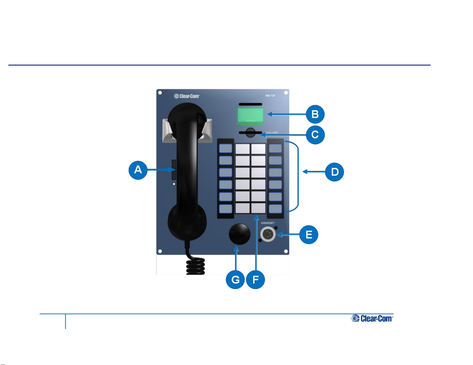
3.1 Industrial KB Station front panel
Figure 3-1 Industrial KB Station front panel
Page 9
9
HelixNet Industrial KB Station User Guide
Key to Industrial KB Station front panel
Feature
Description
A
Handset. The handset contains a Push-To-Talk (PTT) button.
B
OLED display screen. An OLED display that shows three horizontal lines of
text. In normal operating mode the display shows:
The User Name
The audio volume
The profile name. For information about profiles, see 5.5 Profiles.
In Menu mode, the display shows the menu driven configuration options.
If the display is in Menu mode, the display screen times out of Menu mode and
reverts to normal operating mode.
For more information about Menu mode, see 5.1 Using the menus.
C
Audio level rotary control/menu navigation. To increase the volume to the
handset loudspeaker / headphones, turn clockwise (up to 360°). To decrease
the volume, turn counter-clockwise (up to 360°).
D
Customisable call key labels.
E
Handset socket (4-pin XLR–M)
Pin
Function
1
Mic ground
2
Mic positive
3
Earphone ground
4
Earphone positive
Table 3-1 : Headset socket pin out
F
12 station call keys.
G
Audio alert buzzer
Table 3-2 Key to Industrial KB Station front panel
Page 10
10
HelixNet Industrial KB Station User Guide
Phoenix
connectors
for panel
expansion
Ethernet
connector
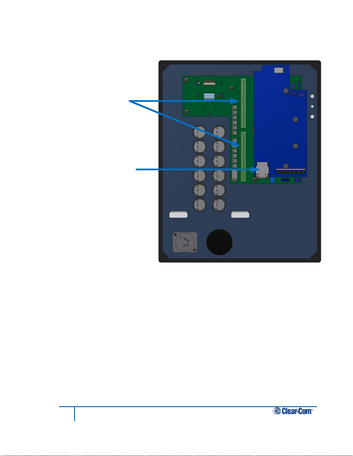
3.2 Industrial KB Station rear panel
3.2.1 DHCP enabled networks
Figure 3-2 Industrial KB Station rear panel
For information on expanding the unit to include more call buttons, see 4.4 Installing the
Industrial KB Station
You can install the Industrial KB Station in a network which has a DHCP server which
automatically assigns IP addresses, or in a network where you manually assign IP addresses.
It is recommended to use a DHCP server if possible.
To install the Industrial KB Station in a network with a DHCP server:
1) Ensure that there is a HelixNet Main Station (HMS-4X) in your network and that the
Main Station is set to DHCP enabled. From the Main Station menu, select
Networking > Preferences > DHCP > Enabled. See the HelixNet Partyline User
Guide for more information.
Note: Enabled is the default Main Station DHCP setting.
Page 11

11
HelixNet Industrial KB Station User Guide
2) From a Web browser, enter the address of the Main Station.
3) From the Configuration Editor tool, configure a new profile for the Industrial KB
Station. See 7.6 Profile Editing screen.
4) Connect an Ethernet cable (cat 5 or higher) from the Ethernet connector on the rear
of the Industrial KB Station (see 3.2 Industrial KB Station rear panel) to a Power
over Ethernet (PoE) switch.
5) If your network contains only one HelixNet Main Station, the Industrial KB Station
automatically pairs with the Main Station.
If there is more than one Main Station, press and hold the rotary control on the front
of the KB Station for four seconds, and then select Networking > Pair to Station >
By Name, and select the name of the required Main Station. See 5.6.1Selecting a
HelixNet Main Station controller.
6) From the KB Station menu, select Profiles, and select the profile that you created in
step 3. See 5.5 Profiles.
3.2.2 Static IP addressed networks
To install the Industrial KB Station using static IP addressing:
1) Ensure that there is a HelixNet Main Station (HMS-4X) in your network.
2) From a Web browser, enter the address of the Main Station.
3) From the Configuration Editor tool, configure a new profile for the Industrial KB
Station. See 7.6 Profile Editing screen.
4) Connect an Ethernet cable (cat 5 or higher) from the Ethernet connector on the rear
of the Industrial KB Station (see 3.2 Industrial KB Station rear panel) to a Power
over Ethernet (PoE) switch.
5) Press and hold the rotary control on the front panel of the KB Station for four
seconds, and then select Networking > Preferences > DHCP > Disable. See 5.6.2
Selecting network preferences.
6) From Networking > Preferences, set the IP Address, Gateway and Subnet mask to
the required settings. See 5.6.2 Selecting network preferences.
7) You must now reboot the Industrial KB Station. Select Administration > Reboot >
Reboot Now.
8) If your network contains only one HelixNet Main Station, the Industrial KB Station
automatically pairs with the Main Station.
If there is more than one Main Station, press and hold the rotary control on the front
of the KB Station for four seconds, and then select Networking > Pair to Station >
Page 12
12
HelixNet Industrial KB Station User Guide
Push-To-Talk
(PTT) button
By Name, and select the name of the required Main Station. See 5.6.1Selecting a
HelixNet Main Station controller.
9) From the KB Station menu, select Profiles, and select the profile that you created in
step 3. See 5.5 Profiles.
Adding extra call buttons to the Industrial KB Station.
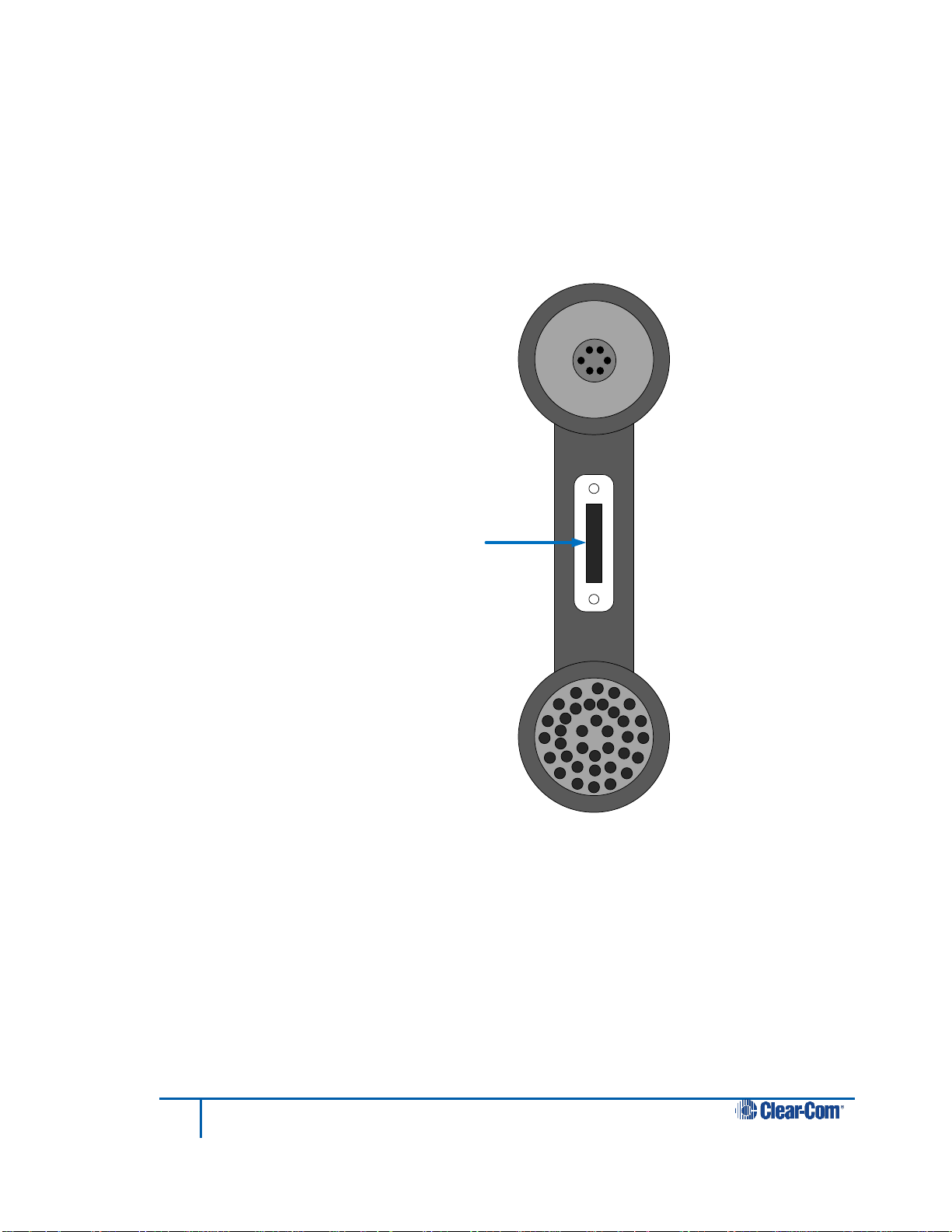
3.3 KB Station handset
Figure 3-3 KB Station handset HS-6 with PTT
Page 13
13
HelixNet Industrial KB Station User Guide
Do not plug any non-approved equipment into HelixNet Partyline.
HelixNet Partyline operates at different voltage levels than analog two-wire
partyline systems. Do not plug any analog two-wire partyline equipment into
the HelixNet partyline ports, as this may cause damage.
For more safety instructions, see 1 Important safety instructions.
4 Installing the Industrial KB Station
This chapter describes how to install your Industrial KB Station.
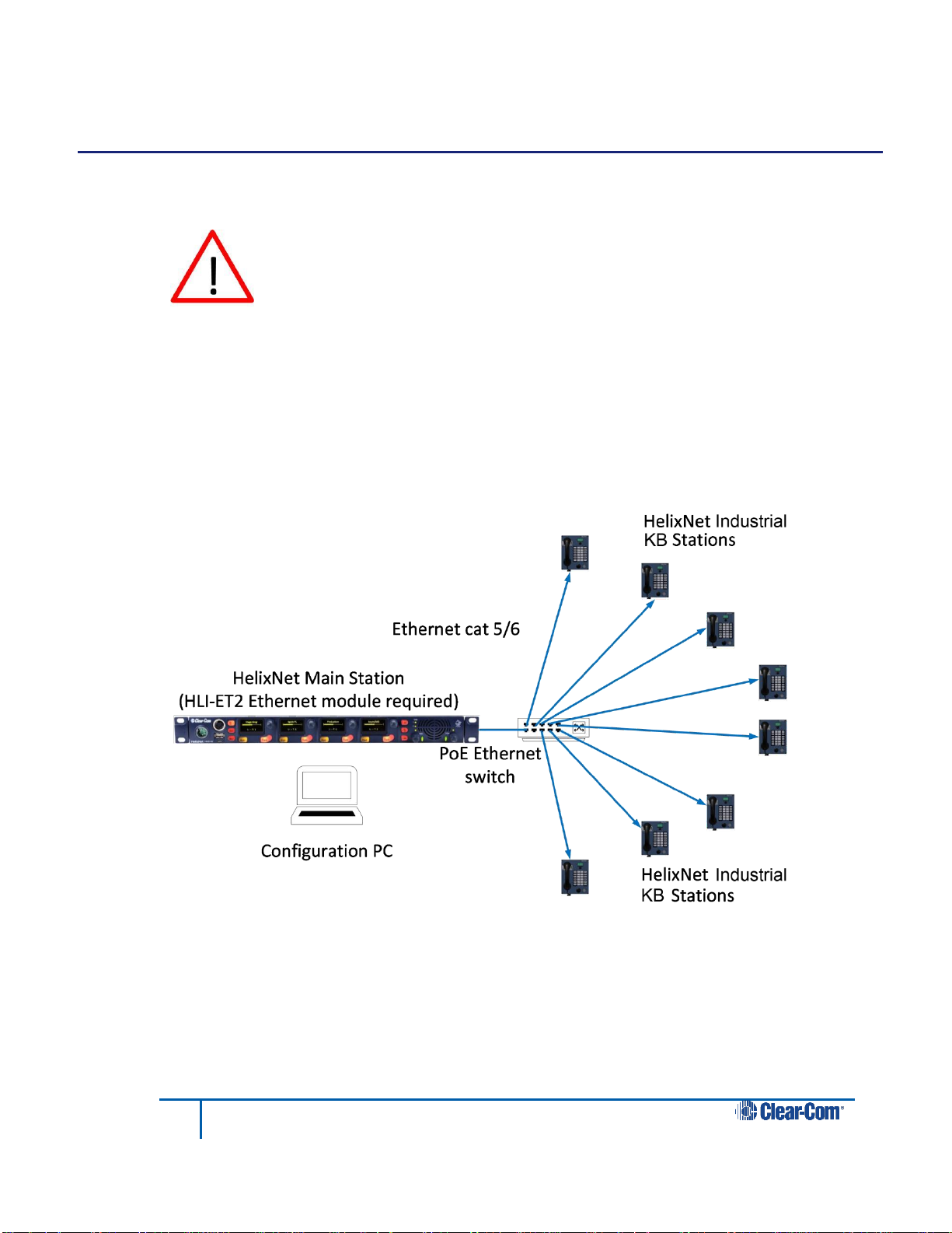
4.1 System overview
Up to 64 user stations are controlled by a HelixNet Main Station using a browser-based
Configuration Editor. The Main Station connects to the Industrial KB Stations over LAN and
each KB Station is powered remotely using PoE (Power over Ethernet). An example of an
intercom system using HelixNet Industrial KB Stations is shown below.
Figure 4-1 HelixNet Industrial KB Station overview
Page 14

14
HelixNet Industrial KB Station User Guide
4.2 Mounting the Industrial KB Station
The Industrial KB Station can be:
Mounted in an enclosure for desktop use
Mounted inside a wall box.
There are four mounting holes located at each corner of the unit that enable you to fix the unit
to your existing desktop or wall-hanging enclosures.
4.3 Connecting the Industrial KB Station
There is no power switch, button or key on the Industrial KB Station. Power is supplied over
Ethernet.
1) Ensure that the desktop or wall-hanging enclosure is connected to the LAN.
2) Ensure that a handset is connected to the handset connector.
3) To ensure that the unit is functioning correctly, initiate a test call. You can do this:
a) Using the browser-based Configuration Editor. See 7.4.4 Making a test call
to a station.
b) From the station by simultaneously pressing call key 1 (top left) and call key
12 (bottom right).
4.4 Installing the Industrial KB Station
You can install the Industrial KB Station in a network which has a DHCP server which
automatically assigns IP addresses, or in a network where you manually assign IP addresses.
It is recommended to use a DHCP server if possible.
4.4.1 DHCP enabled networks
To install the Industrial KB Station in a network with a DHCP server:
4) Ensure that there is a HelixNet Main Station (HMS-4X) in your network and that the
Main Station is set to DHCP enabled. From the Main Station menu, select
Networking > Preferences > DHCP > Enabled. See the HelixNet Partyline User
Guide for more information.
Note: Enabled is the default Main Station DHCP setting.
5) From a Web browser, enter the address of the Main Station.
6) From the Configuration Editor tool, configure a new profile for the Industrial KB
Station. See 7.6 Profile Editing screen.
7) Connect an Ethernet cable (cat 5 or higher) from the Ethernet connector on the rear
of the Industrial KB Station (see 3.2 Industrial KB Station rear panel) to a Power
over Ethernet (PoE) switch.
Page 15

15
HelixNet Industrial KB Station User Guide
8) If your network contains only one HelixNet Main Station, the Industrial KB Station
automatically pairs with the Main Station.
If there is more than one Main Station, press and hold the rotary control on the front
of the KB Station for four seconds, and then select Networking > Pair to Station >
By Name, and select the name of the required Main Station. See 5.6.1Selecting a
HelixNet Main Station controller.
9) From the KB Station menu, select Profiles, and select the profile that you created in
step 3. See 5.5 Profiles.
4.4.2 Static IP addressed networks
To install the Industrial KB Station using static IP addressing:
10) Ensure that there is a HelixNet Main Station (HMS-4X) in your network.
11) From a Web browser, enter the address of the Main Station.
12) From the Configuration Editor tool, configure a new profile for the Industrial KB
Station. See 7.6 Profile Editing screen.
13) Connect an Ethernet cable (cat 5 or higher) from the Ethernet connector on the rear
of the Industrial KB Station (see 3.2 Industrial KB Station rear panel) to a Power
over Ethernet (PoE) switch.
14) Press and hold the rotary control on the front panel of the KB Station for four
seconds, and then select Networking > Preferences > DHCP > Disable. See 5.6.2
Selecting network preferences.
15) From Networking > Preferences, set the IP Address, Gateway and Subnet mask to
the required settings. See 5.6.2 Selecting network preferences.
16) You must now reboot the Industrial KB Station. Select Administration > Reboot >
Reboot Now.
17) If your network contains only one HelixNet Main Station, the Industrial KB Station
automatically pairs with the Main Station.
If there is more than one Main Station, press and hold the rotary control on the front
of the KB Station for four seconds, and then select Networking > Pair to Station >
By Name, and select the name of the required Main Station. See 5.6.1Selecting a
HelixNet Main Station controller.
18) From the KB Station menu, select Profiles, and select the profile that you created in
step 3. See 5.5 Profiles.
4.5 Adding extra call buttons to the Industrial KB Station
You can add extra call buttons to the unit up to a total of 40. To do this:
Page 16

16
HelixNet Industrial KB Station User Guide
SW 13 to
SW 26
SW 27 to
SW 40
GND
GND
1) Access the two phoenix expansion connectors located on the back panel of the
Industrial KB Station.
2) Make the necessary connection as follows. For each extra call button connect the
coresponding switch connection (SW #) to GND.
Page 17

17
HelixNet Industrial KB Station User Guide
5 Configuring the Industrial KB Station
This chapter describes how to configure the settings and manage the Speaker Station using
the display screen configuration menus. There are four menu levels.
Note: You can only use the configuration menus if they are unlocked. To lock or unlock a Station’s
menu, see 7.3 User Stations .
Note: For information about using the PC-based Configuration Editor, see 7 Using the
Configuration Editor.
This chapter contains the following sections:
Using the menus
Configuration settings
Configuring the Audio settings
Station Settings
Station Settings
Networking
Administration
Diagnostics
5.1 Using the menus
To place the Industrial KB Station in Menu mode, press the Audio level rotary
control/menu navigation key for approximately four seconds, see 3.1 Industrial KB Station
front panel.
To exit Menu mode, press the Menu navigation rotary control for approximately four seconds.
Note: Menu mode automatically exits if there is no activity on the front panel keys or rotary controls
for five seconds or longer. If this happens, the display screen returns to its normal operating
configuration.
5.1.1 Selecting menu options
Use the menu displays as follows:
To navigate up or down the list of menu options, turn the rotary control clockwise or
counter-clockwise respectively.
To select a menu option, or to open a list of submenu options, briefly press the rotary
control.
To return to the previous menu screen, press the rotary control for approximately 0.5
seconds.
Note: When the Industrial KB Station is in normal operating mode, the rotary control adjusts the
audio volume of the handset. The volume level appears on the display.
Page 18

18
HelixNet Industrial KB Station User Guide
5.2 Configuration settings
The following menu levels appear in Menu mode:
Audio Settings – use this menu to configure audio volume and quality.
Station Settings – use this menu to configure the station display brightness and
screensaver settings.
Profiles – use this menu to select a profile.
Networking – use this menu to configure the station’s IP settings and to pair to
another station.
Administration – use this menu to reboot the station or to restore the system
defaults.
Diagnostics – use this menu to gain troubleshooting or diagnostic information.
Note: For a complete list of menu options, see 9 Menu maps.
5.3 Configuring the Audio settings
5.3.1 Audio settings for the headset
To configure the audio settings for the headset:
1) In Menu mode, select Audio Settings and then Headset.
Adjusting the level of sidetone on the headset
Sidetone allows you to hear your handset output audio through the handset earpiece.
1) In the third menu, select Sidetone Gain.
2) In the fourth menu, select one of the following:
0dB
- 6dB
- 12dB (default)
- 18dB
3) To enable (confirm) the selected setting, press the rotary control.
Limiting the audio level delivered to the headphones (or to disable headphone
limiting)
1) In the third menu, select Headphone Limit.
2) In the fourth menu, select one of the following:
Off
Page 19

19
HelixNet Industrial KB Station User Guide
+6dB
0dB (default)
- 6dB
3) To confirm the selected setting, press the rotary control.
Note: When Headphone Limit is set to anything but Off, a LIM indication will be
shown on the leftmost display.
Adjusting the headphone gain
1) In the third menu, select Headphone Gain.
2) In the fourth menu, select one of the following:
+12dB
+9dB
+6dB
+3dB
0dB (default)
- 6dB
3) To confirm the selected setting, press the rotary control.
Setting (or disabling) sidetone tracking on the headset
1) In the third menu, select Sidetone Control.
2) In the fourth menu, select one of the following:
Tracking - The sidetone volume will follow (track) the Main volume level.
Non-Tracking - The sidetone volume is set to maximum.
Disabled - Sidetone is disabled.
Note: The default is Tracking.
3) To confirm the selected setting, press the rotary control.
Selecting the type of microphone on the headset
1) In the third menu, select HS Mic Type.
Note: HS = Headset.
2) In the fourth menu, select either of the following types of microphone:
Electret (-15dB)
Page 20

20
HelixNet Industrial KB Station User Guide
Dynamic (0dB) (default)
Dynamic (-10 dB)
3) To confirm the selected setting, press the rotary control.
5.3.2 Audio settings for the microphone
To configure the audio settings for the microphone:
1) In Menu mode, select Audio Settings and then Microphone.
Selecting the Headroom
2) From the third menu, select Headroom.
3) From the fourth menu, select one of the following:
Normal (default)
High - Reduces the analog input gain and increases the digital gain
accordingly. That reduces digital clipping at the A/D converter but
increases the noise floor. This setting is intended for use in
environments with very high background noise.
4) To confirm the selected setting, press the rotary control.
Enabling or disabling the Contour Filter
The Contour filter is a Clear-Com algorithm enhancing speech intelligibility, especially when
whispering or talking at a low volume.
1) From the third menu, select Contour Filter
2) From the fourth menu, select one of the following:
Enabled
Disabled
Note: The default is Enabled.
3) To confirm the selected setting, press the rotary control.
5.3.3 Enabling or disabling the buzzer alert
You can configure the Industrial KB Station to sound a warning buzzer when there is incoming
audio.
To configure the buzzer:
1) In Menu mode, select Audio Settings and then Buzzer.
2) From the fourth menu, select one of the following:
Page 21

21
HelixNet Industrial KB Station User Guide
Enabled
Disabled
Note: The default is Enabled.
3) To confirm the selected setting, press the rotary control.
5.4 Station Settings
5.4.1 Setting the Station ID
To set the Station ID:
1) In Menu mode, select Station Settings and then Station ID.
2) Enter a Station ID. You can enter up to 10 letters or numbers.
3) To confirm the Station ID, press the rotary control.
5.4.2 Setting the display brightness
To set the brightness of the OLED display:
1) In Menu mode, select Station Settings and then OLED Brightness.
2) From the third menu, select one of the following:
High
Medium (default)
Low
3) To confirm the selected setting, press the rotary control.
5.4.3 Setting the display call feature
You can configure the Industrial KB Station to display caller ID when an incoming call arrives.
To set the display call:
1) In Menu mode, select Station Settings and then Display Call
2) From the third menu, select one of the following:
Enabled (default)
Disabled
3) To confirm the selected setting, press the rotary control.
Page 22

22
HelixNet Industrial KB Station User Guide
5.4.4 Setting the screensaver
You can choose to enable the screensaver, and to determine what it displays.
Tip: To exit screensaver mode, press any key on the front panel.
To enable or disable the screensaver:
1) In Menu mode, select Station Settings and then Screensaver.
2) From the third menu, select one of the following:
Station ID (default)
Black screen
Disabled
3) To confirm the selected setting, press the rotary control.
5.5 Profiles
Every Industrial KB Station has a Profile. This is assigned from the Intercom Station menu.
This profile determines the functionality of the call buttons on the front panel.
Note: You can only define and edit the contents of any profile by using the Configuration Editor.
To assign a profile to the Industrial KB Station:
1) In Menu mode, select Profiles.
2) From the second menu, select a profile from the available list of profiles:
3) To confirm the selected setting, press the rotary control.
5.6 Networking
5.6.1 Selecting a HelixNet Main Station controller
Each Industrial KB Station is controlled by a HelixNet Main Station. When the Industrial KB
Station is connected to network, it will detect any Main Stations on the network and display
that station’s ID within the Networking menu. You can select which Main Station to pair with
using the Networking menu. You can select a Main Station by its name or by its IP address.
To select a Main Station by name:
1) In Menu mode, select Networking, and then Pair to Station.
2) From the third menu, select By Name.
3) From the fourth menu, select a Main Station from the list of detected Main Stations.
4) To confirm the selected setting, press the rotary control.
Page 23

23
HelixNet Industrial KB Station User Guide
To select a Main Station by IP address:
1) In Menu mode, select Networking, and then Pair to Station.
2) From the third menu, select By Address.
3) In the fourth menu, enter a Main Station IP address.
4) To confirm the selected setting, press the rotary control.
5.6.2 Selecting network preferences
You can edit the following network parameters:
DHCP
IP address
Gateway
Subnet Mask
Note: If DHCP is enabled, you cannot edit the IP address, gateway or subnet mask.
To enable DHCP:
1) In Menu mode, select Networking, and then Preferences.
2) From the third menu, select DHCP.
3) From the fourth menu, select one of the following:
Enabled (default)
Disabled
4) To confirm the selected setting, press the rotary control.
To edit the IP address:
1) In Menu mode, select Networking, and then Preferences.
2) From the third menu, select IP Address.
3) In the fourth menu, enter or edit the IP address.
4) To confirm the selected setting, press the rotary control.
To edit the gateway:
1) In Menu mode, select Networking, and then Preferences.
Page 24

24
HelixNet Industrial KB Station User Guide
2) From the third menu, select Gateway.
3) In the fourth menu, enter or edit the gateway address.
4) To confirm the selected setting, press the rotary control.
To edit the subnet mask:
1) In Menu mode, select Networking, and then Preferences.
2) From the third menu, select Subnet Mask.
3) In the fourth menu, enter or edit the subnet mask.
4) To confirm the selected setting, press the rotary control.
5.7 Administration
5.7.1 Viewing the current versions of the software
To view the current version of the software:
1) In Menu mode, select Administration > Software
5.7.2 Resetting the system defaults
To reset the Industrial KB Station to its default (factory mode) settings:
1) In Menu mode, select Administration and then Reset To Default.
2) In the third menu select: Reset Now.
3) To confirm the selected setting, press the rotary control.
5.7.3 Manually rebooting the Industrial KB Station
To manually reboot the Industrial KB Station:
1) In Menu mode, select Administration and then Reboot.
2) In the third menu, select Reboot Now.
3) To confirm the selected setting, press the rotary control.
Page 25

25
HelixNet Industrial KB Station User Guide
5.8 Diagnostics
5.8.1 Viewing Ethernet information
1) In Menu mode, select Diagnostics and then Ethernet.
The third menu displays the following information:
Status – The status of the Ethernet
IP Addr – The IP address of the Industrial KB Station
IP Mask – The subnet mask of the Industrial KB Stations
MAC – The MAC address of the Industrial KB Station.
5.8.2 Viewing keysets information
To view information about the keyset:
1) In Menu mode, select Diagnostics and then Keyset.
The third menu displays the following information:
Name – The name of the Industrial KB Station
Talkers – The number of talkers on the partyline
Devices – The number of Industrial KB Stations listening
Main Stations – The number of Main Stations listening.
2-Wire – The number of 2-wire ports listening
4-Wire – The number of 4-wire ports listening
5.8.3 Viewing main PCB information
To view information about the main PCB on the Industrial KB Station
1) In Menu mode, select Diagnostics and then Main PCB.
The third menu displays the following information:
Part – The part number of the main PCB
Revision – The revision number of the main PCB
Serial – The serial number of the main PCB
Page 26

26
HelixNet Industrial KB Station User Guide
6 Using the Industrial KB Station
This chapter describes how to use the Industrial KB Station.
6.1 Using the handset (HS-6)
Ensure that the handset (HS-6) is connected to the station using the 4-pin XLR connector. For
more information, see 3.1 Industrial KB Station front panel.
6.1.1 Making an outgoing call to other intercom users:
1) Lift the handset from its cradle
2) Press and hold one of the Talk keys. The call is routed to all Industrial KB Stations
whose profile is assigned to the key
Note: To program the Talk keys and edit profiles use the Configuration Editor.
3) When you receive a reply, press the Push-To-Talk (PTT) button on the handset and
speak into the microphone. See Figure 3-3 KB Station handset HS-6 with PTT.
4) When the call is finished, replace the handset onto the cradle.
Note: The Intercom Station has infra-red sensors that detect when the handset is replaced on its
cradle after a call. The Configuration Editor uses this information to determine the status of the
Intercom Station. For more information, see 7.4.1 Viewing status information.
6.1.2 Answering an incoming call
If there is an incoming call the OLED display will indicate this. If there is more than one
incoming call, the OLED display cycles through the caller IDs. If the buzzer is enabled, you will
also receive an audible notification. To answer the call:
1) Lift the handset from its cradle and press the Push-To-Talk (PTT) button on the
handset. See Figure 3-3 KB Station handset HS-6 with PTT.
2) Replace the handset when the call is over.
Note: The Intercom Station has infra-red sensors that detect when the handset is replaced on its
cradle after a call. For more information, see 7.4.1 Viewing status information.
6.1.3 Adjusting the volume level:
Adjust the volume of all incoming audio by turning the rotary control located below the OLED
display.
To increase the volume level, turn the rotary control clockwise. To decrease the volume
level, turn the rotary control counter-clockwise.
Page 27

27
HelixNet Industrial KB Station User Guide
7 Using the Configuration Editor
The Configuration Editor is a software tool that you can download to your configuration PC
browser. It offer a quick and easy way to configure HelixNet 2.1. This chapter contains the
following sections:
Introduction
Accessing the Configuration Editor
User Stations screen
Station Details screen
Profiles screen
Profile Editing screen
Change Password screen
7.1 Introduction
The HelixNet Configuration Editor is a browser-based software tool that enables you to view
and manage the HelixNet 2.1 Industrial KB Stations that are present in your HelixNet.2.1
configuration. The Configuration Editor contains five main screens:
The User Stations screen. Use this screen to view a synopsis of the stations
present in your configuration, and the status of each station.
The Station Details screen. Use this screen to view more information about a
station and to change menu lock status. You can also trigger a test call.
The Profiles screen. Use this screen to manage the profiles in your configuration.
You can add, delete, back up and restore profiles.
The Profile Editing screen. Use this screen to edit profiles. This allow you to
determine the call key functionality of each station in your configuration.
The Change Password screen. Use this screen to change the password used to log
into the Configuration Editor.
Each of these screens contains a navigation bar at the top:
The navigation bar shows the name of the HelixNet Main Station that is the controller for the
Industrial KB Stations. You can navigate between screens using the menu buttons. The
Figure 7-1 Navigation bar
Page 28

28
HelixNet Industrial KB Station User Guide
current page is highlighted. Clicking on the Clear-Com logo opens the Clear-Com website
home page, www.clearcom.com.
7.2 Accessing the Configuration Editor
To access the Configuration Editor, enter the IP address of the HelixNet Main Station that is
acting as the HelixNet 2.1 controller into an internet browser address field. You can use any of
the following browsers:
Microsoft internet Explorer, version 10 and later
Mozilla Firefox, version 33 and later
Google Chrome, version 34 and later
7.3 User Stations screen
When you open the Configuration Editor, the User Stations page displays. This shows a
graphical representation of all the Industrial KB Stations present in your configuration.
Note: This page is refreshed every 10 seconds to ensure that the information is up to date.
Each station is represented as an icon with the following information:
Station name. A descriptive name for the station. To edit the station name, see 7.4.2
Renaming a station.
Profile. The profile that is assigned to the station. This determines the station’s call
key functionality.
IP address. The current IP address of the station.
Online status. This icon indicates that the station is online (green arrow) or offline
(red cross).
Note: If a station is offline, click the offline status icon to remove the station from
the screen.
Figure 7-2 User Stations
Page 29

29
HelixNet Industrial KB Station User Guide
Handset status. This icon indicates that the handset is onhook (white icon) or off
hook (red icon).
7.4 Station Details screen
To access more detailed information about any station, click the required station on the User
Stations page. The following screen appears.
Figure 7-3 Station Details
From this screen you can:
View status information about the station
Rename the station
Lock or unlock the station’s menu
Make a test call to a station
7.4.1 Viewing status information
You can view the following status information:
Online status (online of offline)
Handset status (onhook or offhook)
Menu lock status (locked or unlocked)
Call status (calling or not calling)
Call key profiles. This shows what profiles are assigned to each key. For more
information about profiles, see 5.5 Profiles.
Page 30

30
HelixNet Industrial KB Station User Guide
7.4.2 Renaming a station
To rename a station, select the station name in the top left of the screen and edit it as
required.
7.4.3 Locking or unlocking a station’s menu
Before a station can be configured using its display panel, the station’s menu must be
unlocked. Alternatively, you can lock the menu to prevent user’s reconfiguring the station.
To lock or unlock the menu:
Click the Menu icon. The icon toggles between Locked and Unlocked.
7.4.4 Making a test call to a station
You can trigger a test call to a station to ensure that the station is connected properly and can
receive and send audio.
To trigger a test call:
Click the Test Call button in the top right of the screen.
7.4.5 Viewing Call key profiles
The Station Details screen list the station’s call keys. For each call key, all the associated
profiles are listed. To manage or edit station profiles, see 7.6 Profile Editing screen.
7.5 Profiles screen
The Profiles screen allows you to manage the profiles in your configuration. To access the
Profiles screen, select Profiles from the navigation bar.
Figure 7-4 Profiles screen
Page 31

31
HelixNet Industrial KB Station User Guide
From the Profiles screen you can:
View the stations allocated to each profile. To edit this information, see 7.6 Profile
Editing screen.
Add or delete profiles
Create a profiles database backup
Restore a previous profile backup
Access the Profiles Editing screen. Click on any profile to enter the Profile Editing
screen.
7.5.1 Adding and deleting profiles
To add a new profile to your configuration:
Enter the profile name in the top left edit field, and then click +.
To delete a profile from your configuration:
1) Click Delete. The screen now changes to Delete mode.
2) Click the Delete button on the profile that you wish to delete.
7.5.2 Creating a profile database backup
To create a profile database backup:
Click Backup, and navigate to the preferred backup location.
7.5.3 Restoring a profiles backup
To restore a previously created backup:
Click Restore, and navigate to the location of the backup.
7.6 Profile Editing screen
The Profile Editing screen allows you to edit the profiles in your configuration. To access the
Profile Editing screen, click on the required Profile in the Profiles screen.
Page 32

32
HelixNet Industrial KB Station User Guide
Figure 7-5 Profile Editing screen
From the Profile Editing screen you can:
View a list of station Call keys, and see which profiles are associated with each Call
key.
Rename a profile
Add profiles to a Call key
Remove profiles from a Call key
7.6.1 Renaming a profile
To rename a profile:
Click the profile name at the top left of the screen and edit it as required.
7.6.2 Adding a profile
To add a profile to a key:
1) For the required key, click +.
2) Select the required profile.
7.6.3 Removing a profile
To remove a profile from a key:
For the required key profile, click the delete icon
Page 33

33
HelixNet Industrial KB Station User Guide
7.7 Change Password screen
To access the Change Password screen, select
Figure 7-6 Change Password screen
To change your password:
1) In the Old Password edit field, enter your current password.
2) In the New Password edit field, enter your new password.
3) In the Confirm New Password edit field, re-enter your new password
4) Click Change Password.
Page 34

34
HelixNet Industrial KB Station User Guide
Specification
Description / value
Handset
One 4-pin male XLR.
Ethernet/Power over Ethernet
RJ-45
Specification
Description / value
Handset Mic impedance:
200 Ω (Dynamic)
Mic limiter range
>35 dB
Mic gain
60dB (dynamic)
Frequency response
400 Hz – 8 kHz + / -3dB (contoured for intelligibility)
Distortion
<0.5% THD @ 1 kHz
Noise-
<-55dBu dynamic
8 Specifications
8.1 Industrial KB Station (IKB-12P)
8.1.1 Connectors
Table 8-1: Station: Connectors
8.1.2 Microphone pre-amplifier
Table 8-2: Station: Microphone pre-amplifier
Page 35

35
HelixNet Industrial KB Station User Guide
Specification
Description / value
Load impedance
>32 Ω
Output level
+12dBu before clipping
Sidetone
-6dB (selectable)
The following specified for a route from a 4-wire input @0dBu in:
Max gain
12dB
Noise
<-65dBu (@ max gain)
Headphone limiter
-0dBu (selectable)
Specification
Description / value
Fast Ethernet standard
100BaseT only, Auto MDIX
Specification
Description / value
Power requirements
5W
DC Voltage range
30 – 60Volts
Specification
Description / value
Temperature
-10˚C to +55˚C (-14 to 131˚F)
Humidity
0 - 95% relative humidity
8.1.3 Earphone amplifier
8.1.4 Ethernet
Table 8-3: Station: Headphone amplifier
8.1.5 Power requirements
8.1.6 Environmental
Table 8-4: Station: Ethernet
Table 8-5: Station: Power requirements
Table 8-6: Station: Environmental
Page 36

36
HelixNet Industrial KB Station User Guide
Menu 1 (First) >
Menu 2 >
Menu 3>
Menu 4 (Last )
Audio Settings
Headset
Sidetone Gain
Range: 0dB to -18dB
Default: -12db
Headphone Limit
Off + Range: +6dB to -6dB
Default: 0db
Headphone Gain
Range: 0 to +12dB
Default: 0dB
Sidetone Control
Tracking
Non-Tracking
Disabled
Default: Tracking
HS Mic Type
Electret (-15dB)
Dynamic (0 dB)
Dynamic (-10 dB)
Default: Dynamic (0 dB)
Microphone
Headroom
Normal
High
Default: Normal
9 Menu maps
IKB-12P Industrial KB Station menu map
Page 37

37
HelixNet Industrial KB Station User Guide
Menu 1 (First) >
Menu 2 >
Menu 3>
Menu 4 (Last )
Contour Filter
Enabled
Disabled
Default: Enabled
Buzzer
Enabled
Disabled
Default: Enabled
None
Station Settings
Station ID
Station ID entry
Alphanumeric entry
None
OLED Brightness
High
Medium
Low
Default: Medium
None
Display Call
Enabled
Disabled
Default: Enabled
None
Screensaver
Station ID
Black Screen
Disabled
Default: Station ID
Profiles
None
None
None
Page 38

38
HelixNet Industrial KB Station User Guide
Menu 1 (First) >
Menu 2 >
Menu 3>
Menu 4 (Last )
Profile_1
Profile_2
…..
Network
Pair to Station
By Name
By Address
Station IDs
IP address: xx.xx.xx.xx where x is a numeric value
Preferences
DHCP
Enabled
Disabled
Default: Enabled
IP Address
IP address: xx.xx.xx.xx where x is a numeric value
Gateway
IP address: xx.xx.xx.xx where x is a numeric value
Subnet Mask
IP address: xx.xx.xx.xx where x is a numeric value
Administration
Software
Software system version
None
Reset To Default
Reset now
Reboot
Reboot now
Diagnostics
Ethernet
Status
IP Address
IP Mask
MAC
Page 39

39
HelixNet Industrial KB Station User Guide
Menu 1 (First) >
Menu 2 >
Menu 3>
Menu 4 (Last )
Keyset
Name: Industrial KB Station name
Talkers: Number of talkers
Devices: Number of Industrial KB Stations
listening on party line
Main Stations: Number of Main Stations listening
2-Wire: Number of 2-Wire ports listening
4-Wire: Number of 4-Wire ports listening
Page 40

40
HelixNet Partyline User Guide
10 Compliance
FCC notice
This device complies with Part 15 of the FCC rules. Operation is subject to the following two
conditions: (1) This device may not cause harmful interference, and (2) This device must
accept any interference received, including interference that may cause undesired operation.
NOTE: This equipment has been tested and found to comply with the limits for a Class A
digital device, pursuant to Part 15 of the FCC rules. These limits are designed to provide
reasonable protection against harmful interference when the equipment is operated in a
commercial environment. This equipment generates, uses and can radiate radio frequency
energy and, if not installed and used in accordance with the instruction manual, may cause
harmful interference to radio communication. Operation of this equipment in a residential area
is likely to cause harmful interference, in which case the user will be required to correct the
interference at his own expense.
Changes or modifications not expressly approved by Clear-Com, LLC, an HM Electronics, Inc.
company could void the user’s authority to operate this equipment.
Industry Canada Compliance Statement
This Class[A] digital device complies with Canadian ICES-003.
Avis de conformité à la réglementation d'Industrie Canada
Cet appareil numérique de la class[*] est conforme à la norme NMB-003 du Canada.
This equipment complies with the following specifications:
EN55022 Emissions
EN55024 Immunity
Electromagnetic Compatibility Directive 2004/108/EC
Low Voltage Directive 2006/95/EC
Warning:
This is a Class A product. In a domestic environment this product may cause radio
interference in which case the user may be required to take adequate measures.
This equipment complies with the following specifications:
UL 60065-7
CAN/CSA-C22.2 No.60065-3
IEC 60065-7
Waste Electrical And Electronic Equipment (WEEE)
Page 41

41
HelixNet Partyline User Guide
The European Union (EU) WEEE Directive (2002/96/EC) places an obligation on producers
(manufacturers, distributors and/or retailers) to take-back electronic products at the end of
their useful life. The WEEE Directive covers most Clear-Com products being sold into the EU
as of August 13, 2005. Manufacturers, distributors and retailers are obliged to finance the
costs of recovery from municipal collection points, reuse, and recycling of specified
percentages per the WEEE requirements.
Instructions for Disposal of WEEE by Users in the European Union
The symbol shown below is on the product or on its packaging which indicates that this
product was put on the market after August 13, 2005 and must not be disposed of with other
waste. Instead, it is the user’s responsibility to dispose of the user’s waste equipment by
handing it over to a designated collection point for the recycling of WEEE. The separate
collection and recycling of waste equipment at the time of disposal will help to conserve
natural resources and ensure that it is recycled in a manner that protects human health and
the environment. For more information about where you can drop off your waste equipment
for recycling, please contact your local authority, your household waste disposal service or the
seller from whom you purchased the product.
Figure 10-1: WEEE Symbol
 Loading...