

Page 1
User Manual
Nord Wave
OS Version 2.x
Part No. 50303 Copyright Clavia DMI AB 2009
Print Edition: 2.0
Page 2
The lightning ash with the arrowhead symbol within an
equilateral triangle is intended to al ert the user to the
presence of uninsulated voltage within the products
enclosure that may be of sufcient magnitude to constitute
a risk of electric shock to persons.
Le symbole éclair avec le point de èche à l´intérieur d´un triangle
équilatéral est utilisé pour alerter l´utilisateur de la presence à
l´intérieur du coffret de ”voltage dangereux” non isolé d´ampleur
sufsante pour constituer un risque d`éléctrocution.
The exclamation mark within an equilateral triangle is
intended to alert the user to the presence of important
operating and maintenance (servicing) instructions in the
literature accompanying the product.
Le point d´exclamation à l´intérieur d´un triangle équilatéral est
employé pour alerter l´utilisateur de la présence d´instructions
importantes pour le fonctionnement et l´entretien (service) dans le
livret d´instructions accompagnant l´appareil.
Instructions pertaining to a risk of re, electric shock or injury to persons.
IMPORTANT SAFETY INSTRUCTIONS
SAVE THESE INSTRUCTIONS
CAUTION AVIS
RISK OF ELECTRIC SHOCK
DO NOT OPE
N
RISQUE DE SHOCK ELECTRIQUE
NE PAS OUVRIR
CAUTION: TO REDUCE THE RISK OF ELECTRIC
SHOCK DO NOT REMOVE COVER (OR BACK).
NO USER SERVICEABLE PARTS INSIDE.
REFER SERVICING TO QUALIFIED PERSONNEL.
ATTENTION :POUR EVITER LES RISQUES DE CHOC
ELECTRIQUE, NE PAS ENLEVER LE COUVERCLE.
AUCUN ENTRETIEN DE PIECES INTERIEURES PAR L´USAGER.
CONFIER L´ENTRETIEN AU PERSONNEL QUALIFE.
AVIS: POUR EVITER LES RISQUES D´INCIDENTE OU
D´ELECTROCUTION, N´EXPOSEZ PAS CET ARTICLE A LA PLUIE
OU L´HUMIDITET.
Warning - When using electric products, basic
precautions should always be followed, including
the following:
1. Read all the instructions and observe the graphic
symbols above before using the product.
2. Do not use this product near water - for example
near a bathtub, washbowl, kitchen sink, in a wet
basement, near or in a swimming pool, a swamp or
the like.
3. This product should be used only with a cart or a
stand that is recommended by the manufacturer.
4. This product, either alone or in combination with an
amplier and headphones or speakers may be
perfectly capable of producing sound levels that
could cause permanent hearing loss. Do not
operate for a long period of time at a high volume
level or at a level that is uncomfortable. If you
experience any hearing loss or ringing in the ears,
you should consult an audiologist.
5. The product should be located so that its location
or position does not interfere with or obstruct its
normal ow of ventilation.
6. The product should be located away from heat
sources such as radiators, heat registers or other
products that produce heat.
7. The product should be connected to a power
supply only of the type described in these operation instructions or as marked on the product.
8. The power supply cord of the
product should be unplugged
from the outlet when the product is left unused for a long
period of time.
9. Care should be taken so that objects do not fall, or liquids
are not spilled into the enclosure through openings.
10. The product should be serviced by qualied service personnel when:
A. The power supply cord has been damaged; or
B. Objects have fallen or liquids have been spilled onto the
product; or
C. The product has been exposed to rain; or
D. The product does not appear to operate normally or
exhibits a marked change in performance; or
E. The product has been dropped or the enclosure has
been damaged.
11. Do not attempt to service the product beyond those means
described in this operating manual. All other servicing
should be referred to qualied service personnel.
12. To completely disconnect the apparatus from the mains,
remove the mains plug.
13. Ensure possible protective earthing connections of other
equipment when the apparatus is connected to multimedia
systems.
13. Where the Mains plug is used as the disconnect device, the
disconnect device shall remain readily operable.
Trademarks: The Nord logo is a registred trademark of Clavia DMI AB. All other trademarks mentioned in this publication are the properties of their respective holders.
Specications and appearances are subject to change without notice.
Copyright by Clavia DMI AB, 2008
Page 3

| 3
Nord Wave User Manual
Output ........................................30
1Introduction
Thank you! .....................................5
Development story .............................5
Features ........................................5
Synthesizer .......................................5
Morph ...........................................5
Slots ............................................5
Programs.........................................5
Effects ...........................................5
Sample Instruments ................................5
Nord Sample Editor.................................6
Control s & conne ctions ..............................6
More samples ..................................6
2Panel Overview
The Front Panel ................................7
Progra m & Perfor manc e area .........................7
Synth ar ea ........................................7
Effec t area ........................................7
LCD .............................................8
Knobs & dials ..................................8
Knobs ...........................................8
The Rota ry dia l ....................................8
LED-dials.........................................8
Master Le vel kno b..................................8
Buttons .........................................8
Selector buttons ...................................8
On/Of f butto ns ....................................8
Shif t button .......................................8
3Connections
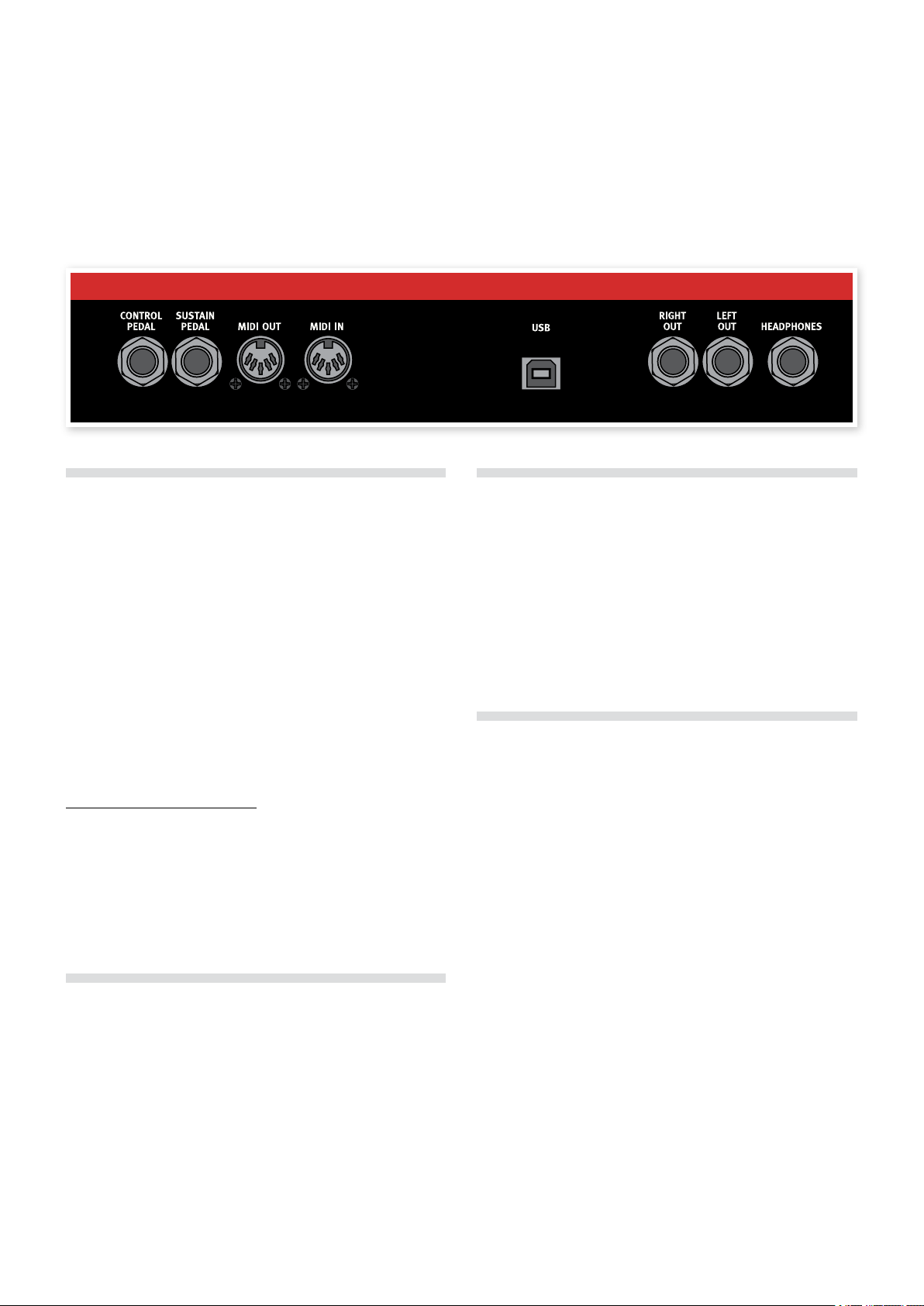
Audio Connections..............................9
Left ou t and rig ht out................................9
Headphones . . . . . . . . . . . . . . . . . . . . . . . . . . . . . . . . . . . . . . 9
MIDI Connections...............................9
MIDI OUT.........................................9
MIDI IN ..........................................9
USB Connection ................................9
Pedal Connections..............................9
Sustai n pedal .....................................9
Control p edal......................................9
4Getting Started
About Programs ...............................10
Selec t a Progra m .................................10
Edit a Prog ram ...................................10
Saving a Pr ogram .................................10
Saving a Pr ogram w ith a new na me and/or c ategor y......11
Slots ...........................................11
Switch be tween t wo sounds ........................11
Layering.........................................11
Deacti vating S lots .................................11
Copyin g a settin g from on e Slot to anot her .............11
Focus ..........................................11
Adding an effect...............................12
A quick MIDI Setup............................12
Control ling Sl ot A and B on se parate MI DI Chan nels ......12
5The Morph Function
About Morphing ...............................13
Morph Sources ................................13
Assig n a Morph so urce to a de stinati on ................13
Morph Mode .....................................14
Morph Destinations................................14
Morph Examples ..............................14
6Nord Wave Reference
Master Level knob ............................15
MIDI LED in dicato r ................................15
Store Button ...................................15
Saving a Pr ogram w ith a new na me and/or c ategor y......15
Program Up/Down buttons ....................15
Rotary Dial ....................................16
Octave Shift buttons ..........................16
Global O ctave ....................................16
Panic ...........................................16
Mono Mode....................................16
Mono Mod e butto n ................................16
Sound Init .......................................16
Glide k nob.......................................16
Morph Buttons ................................16
Assig n a Morph so urce to a de stinati on ................17
Morph Mode .....................................17
LCD Window ...................................17
Slot Buttons ...................................17
System bu tton ....................................17
MIDI but ton ......................................17
Chord Button ..................................17
Sort M ode .......................................18
Vibrato ..........................................18
SAMP Ini t .......................................18
Shift Button ...................................18
LFOs (LFO1 & LFO2) ...........................18
Rate knob .......................................19
Waveform Selector ................................19
LFO Dest inatio n Selec tor ...........................19
Amount k nob ....................................19
Poly mod e .......................................19
Single mode .....................................19
Modulation Envelope (MOD ENV) .............19
Attack k nob......................................20
DEC/REL k nob ...................................20
AR butto n (Shif t + Desti nation S elect b utton) ............20
Amount k nob ....................................20
Destin ation se lector ...............................20
Oscillators (OSC1 & OSC2) ....................20
Oscillator Waveform selector ........................20
Pulse ...........................................21
Sawtoo th........................................21
Triangle .........................................21
Wavetable .......................................21
Sample Instruments ...............................21
Sampled waves...................................21
FM-Syn thesi s ....................................21
FM Algorithms....................................22
Sine ............................................23
Shape pa ramete r (Shap e1 & Shape2/dec) ..............23
Semi Tones k nob .................................24
Fine tun e knob ...................................24
Oscillator Modulation (Osc Mod)..............24
Amount k nob ....................................24
Type button ......................................24
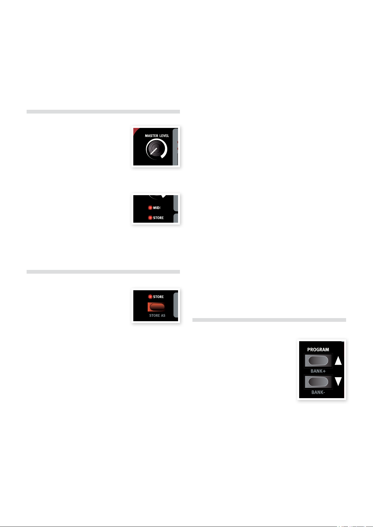
Oscillator mix (Osc Mix).......................24
Mix kno b . . . . . . . . . . . . . . . . . . . . . . . . . . . . . . . . . . . . . . . . 24
Oscillator Sync (Sync) .........................25
Amplier Envelope (AMP ENV)................25
Attack k nob......................................26
Decay k nob ......................................26
Sustai n knob .....................................26
Relea se knob ....................................26
Filter ...........................................27
Type button ......................................27
Low Pass........................................27
High Pas s .......................................27
Band Pas s.......................................27
Comb ..........................................27
Multi............................................28
Vocal ..........................................28
Filter Fre quenc y (Freq kn ob) .........................28
Filter Re sonan ce (Res k nob) .........................28
Keyboar d Tracking (K B Track butto n) ..................28
Filter Sl ope (Sl ope but ton)...........................28
Velocity button ...................................29
Filter Envelope.................................29
Envelop e Amoun t (ENV AMT k nob)....................30
Attack k nob......................................30
Decay k nob ......................................30
Sustai n knob .....................................3 0
Relea se knob ....................................30
Level kn ob.......................................30
Equalizer (EQ) .................................30
Treble knob ......................................30
Bass kn ob .......................................30
Chorus .........................................31
Chorus b utton ....................................31
Program Effects ...............................31
Delay ...........................................31
Tempo LED . . . . . . . . . . . . . . . . . . . . . . . . . . . . . . . . . . . . . . 31
Tempo knob .....................................31
Feedba ck butto n..................................31
Stereo bu tton ....................................31
Amount k nob ....................................31
Tap Tempo button .................................31
On/Of f butto n ....................................31
Tube Amp .......................................31
Drive k nob .......................................31
On/Of f butto n ....................................31
Reverb..........................................31
Dry/ Wet knob ....................................31
Reverb b utton ....................................31
On/Of f butto n ....................................31
7Nord Sound Manager
System re quirem ents ..............................3 2
Overview ......................................32
The Toolbar ......................................32
The Tabs . . . . . . . . . . . . . . . . . . . . . . . . . . . . . . . . . . . . . . . . 32
Parti tion Mem ory In dicator ..........................32
Right-Clicking ....................................32
Selec t in Instr ument ...............................33
Upload..........................................33
Download .......................................33
Rename.........................................33
Delete ..........................................33
File Formats......................................33
The Quick Tour ................................33
Transfer sa mples to th e Wave ........................33
Deleti ng a samp le .................................33
Downlo ad a new sam ple ............................33
Upload s ounds f rom the Wave .......................34
Upload a c omple te parti tion to the h ard dri ve............34
Downlo ad sound s to the Wave .......................34
Organi ze the pro gram par tition.......................34
Search B ox ......................................34
Auto Sele ct ......................................34
Nord Sound Manager reference ...............35
Too lba r .........................................35
Menus .........................................36
File ............................................3 6
Edit ............................................36
View............................................36
Help............................................37
Tabs ...........................................37
Samp Li b - Progra m ...............................37
Search B ox ......................................37
Loc - Locat ion ....................................37
Name...........................................37
Category ........................................37
Size ............................................37
Ver – Versio n Numbe r ..............................37
Info ............................................37
Footer Are a ......................................37
Parti tion Mem ory In dicator ..........................37
Cancel B utton ....................................37
Progres s Bars ....................................37
Messa ge/Text A rea ................................37
Updates a nd samp les ..............................37
Page 4

4 | NordWaveUserMaNUalv2.x
8Nord Sample Editor
What is the Nord Sample Editor? .............38
Non-destructive editing.............................38
System Requirements..............................3 8
Getting Started ................................38
Projec t, sampl e memor y ...........................38
WYDIWYH.......................................38
Workin g offlin e ...................................3 8
Sample, Zone ....................................3 8
Sample Instrument ................................38
Sample e ditin g, loop ma rkers, c rossfa de ...............39
Gener ate, uploa d, downl oad.........................39
Installation ....................................39
Instal lation of t he USB dri ver .........................39
Instal lation W indows PC ............................39
Instal lation M ac OSX ...............................39
The Quick Tour ...............................39
First Li ght .......................................39
Download Sample Instruments.......................40
Upload Sample Instruments . . . . . . . . . . . . . . . . . . . . . . . . .4 0
Create a ne w Sample I nstru ment .....................40
Adding Au dio file s with in divid ual sam ples ..............41
Single Sample Per File Assign........................41
Editing ..........................................42
Looping.........................................42
Gener ate a Sampl e Instr ument ......................43
Menu Reference ...............................44
File Me nu........................................44
Edit Men u .......................................44
Instru ment Me nu ..................................44
Settin gs Menu ....................................44
Manage r Menu ...................................44
Help Me nu.......................................45
Tab Reference .................................45
Common a rea ....................................45
Audio File/Assign Tab .........................46
Single S ample Pe r File As sign .......................46
Multi Sa mple Per F ile Ass ign ........................47
Manua l Sampl e Assig n .............................47
Sample Loop/Stop Ta b ........................47
Long Loo p.......................................48
Short L oop ......................................49
No Loop ........................................49
Apply o n All ......................................4 9
Sample Start Tab ..............................49
Sample Alt Start Tab ..........................49
Instrument Tab ................................50
Sample G ain gr id .................................50
Keyboar d Gain gr aph ..............................50
Detune..........................................50
Sample Zone.....................................51
Transpose .......................................51
Auto Map........................................51
Play Mode .......................................51
Samp Preset Tab ..............................51
Velocity Controlled Dynamics ........................51
Keyboard Controlled Amplifier Envelope................52
Octave Shift......................................52
Manager Tab ..................................52
Manage r Toolbar ..................................52
Right-click.......................................52
List he adline s ....................................53
Footer Memory Indicator............................53
File Types an d Name s..............................53
11MIDI
MIDI Menu ....................................60
MIDI Con trol Loc al ................................60
MIDI Cha nnel.....................................60
MIDI Ctr l A Chann el................................60
MIDI Ctr l B Chann el................................60
MIDI Con trol Cha nge Mod e .........................60
MIDI Prog ram Cha nge Mod e ........................60
MIDI Sen d CC ....................................6 0
MIDI Dum p One ..................................60
MIDI Sen d Bank ..................................61
MIDI Rec eive Ba nk ................................61
MIDI Controller list ............................61
MIDI Imp lemen tation C hart ..........................62
12Appendix
Specications .................................63
Description of Program Categories ...........63
Mellotron Sound Library ......................64
Conde nsed Me llotron s tory..........................64
Histor y of the Mel lotron so unds ......................64
Use of the Me llotro n sounds .........................64
Soundlist with comment s .....................65
Mk I Lead so unds .................................65
MkII Lea d sounds .................................65
M300 Le ad sound s ...............................65
M400 Lea d sounds ...............................65
13Index
9Synthesis Basics
Introduction ...................................54
The “bui lding b locks” ..............................54
The Oscillators and waveforms ...............54
The Filter ......................................56
The Amplier ..................................57
Envelopes .....................................58
LFOs ...........................................58
10System Menu
System Menu ..................................59
Transpose .......................................59
Fine tune ........................................59
Pitch Ben d.......................................59
Vibrato r ate ......................................59
Sustai n Pedal Po larit y ..............................59
Control P edal Type ................................59
Control P edal De stinati on ...........................59
Displa y Mode Ho ld ................................59
Memor y Protec t ..................................59
Page 5

1INtrodUctIoN | 5
Introduction
1
Synthesizer
Thank you!
First we would like to thank you for purchasing the Nord Wave. The
Nord Wave is built on Clavia’s legacy of making virtual analog synthesizers for more than 15 years and we hope you will have as much fun
owning the instrument, as we had developing it.
Development story
To us, details are everything - and an intuitive user interface is just as
important as the actual sound. We are musicians ourselves, and know
by experience how frustrating it can be to have to wade through menus
and page-plus buttons to change a setting.
That is why we have a physical button or knob for every sound related
parameter on the Nord Wave front panel. We also know the importance
of building our instruments as light as possible - some times it is a long
walk to that gig.
Our vision in designing and combining our own hardware and software
is to have professional sound quality and playability in every single
component; from the moment you strike a key to the audio output.
Our patented pitch stick is a perfect example on how dedicated hardware and software extends playability. Once you get familiar with it you
are likely to dismiss all other pitch controllers as a toys.
Since we are working in a digital domain, we can do a lot of interesting stuff with our virtual analog synthesizer that would not be possible
if it was analog-for-real. We have provided the Nord Wave with a very
impressive and useful set of both analog and digital features.
Morphing is a Nord speciality; if there is one chapter in this manual you
must read - it’s the one about morphing. This is very intuitive yet extremely powerful, and will change not only how you play but also your
entire approach to sound design.
With the ability to use any kind of sampled waveform, the Nord Wave
is a sample player and an analog synthesizer in one - and anything
in-between.
In an classical analog style synthesizer environment, each of the
Nord Wave’s two slots consist of 2 oscillators, 2 LFOs, 1 modulation
envelope, 1 amplifier envelope and a multi-type filter section with an
envelope as well.
Oscillator 1 can produce wavetable, FM, analog and noise wave-•
forms. The traditional analog waveforms (Pulse, Triangle, Saw and
Sine) can also operate in a oscillator sync-mode.
Oscillator 2 can produce sampled waves, FM, analog waveforms •
and multi-sample Sample Instruments, and function as a modulation
source for Oscillator 1. The sampled waves are acoustic samples
turned into wavetables with the attack part of the sample intact.
Sample Instruments allows you to use any standard .wav file as an •
oscillator source in a virtual analog environment.
The LFOs have a wide array of modulation destinations several wave-•
forms and the ability to run in Poly and Single mode.
The Modulation Envelope also has a wide array of modulation des-•
tinations and can function either as a attack/decay or as a attack/
release envelope.
The filter section has envelope and velocity control. You have the •
option of resonant high pass, band pass and low pass modes as well
as comb, multi and vocal modes.
Morph
The Morph function lets you continuously control defined ranges of
several parameters in a Program, using only a single control source.
This allows you to produce radical changes in a sound in a very fast
and easy way.
Slots
Each of the two slots also feature a 2-band EQ, chorus, controls for the
output level, mono/legato, glide and vibrato functions.
Programs
There are 1024 program locations, organized in 8 banks in the
Nord Wave where you can store your own programs. Both the individual Slots A & B settings are stored within a program.
Features
The Nord Wave is a virtual analog synthesizer with an extensive set of
functions that allows you to shape the sound in a variety of ways. The
Wave is bi-timbral, it’s two slots are independent of each other, making
it possible to e.g. layer two sounds on top of each other.
The Nord Wave is also a true stereo synthesizer, the signal paths for
the left and the right outputs are separated at the very core in the
sound engine.
Effects
Each program can be processed with a tube style overdrive, a stereo
delay and/or a reverb.
Page 6

6 | NordWaveUserMaNUalv2.x
Sample Instruments
User recorded samples can be downloaded as Sample Instruments to
the Nord Wave via USB. The capacity of the Flash memory is 99 available memory locations, with a maximum total size of 180 MB. Samples
are compressed before they are downloaded using a lossless algorithm
that Clavia has developed. This allows the sample data sizes to be
reduced to up to a third of its original size.
The memory is of the Flash type which means that the Sample Instruments remains in the memory when the synth is turned off. You do not
have to use hard drives or other types of storage media; once loaded
into the memory the data will be there until you decide to remove it!
Nord Sample Editor
The Nord Sample Editor is the application that allows you to edit, create and load collections of samples - called Sample Instruments - to
and from the sample memory area of the Nord Wave synthesizer. This
area is what we call the Flash memory. Another application, the Nord
Sound Manager will also act as a librarian utility for the samples and
the Program memory area.
The Nord Sample Editor will assist you in your editing efforts; it contains
powerful tools for various actions that can be applied to a sample.
These tools will for instance help you in setting a start point of a
sample, creating a loop and other tasks that are essential in making the
samples ready for use in the Nord Wave. The Editor also has functions
for automatic mapping of samples across the keyboard and much
more.
Controls & connections
The Nord Wave has a 49-key keyboard which responds to velocity and
aftertouch. It is also equipped with a modulation wheel and wooden
pitch stick, 2 line level outputs, 1 headphone output, MIDI IN & OUT, a
USB port and inputs for a sustain pedal and a control pedal.
More samples
More high quality Sample Instruments can be downloaded free of
charge from the Nord web site: www.nordkeyboards.com
Both applications are delivered free of charge with every Nord Wave,
and is compatible with computers running Windows XP or Vista. They
can also run on a Macintosh with Mac OSX 10.4 or later.
Page 7
2PaNelovervIeW | 7
Panel Overview
2
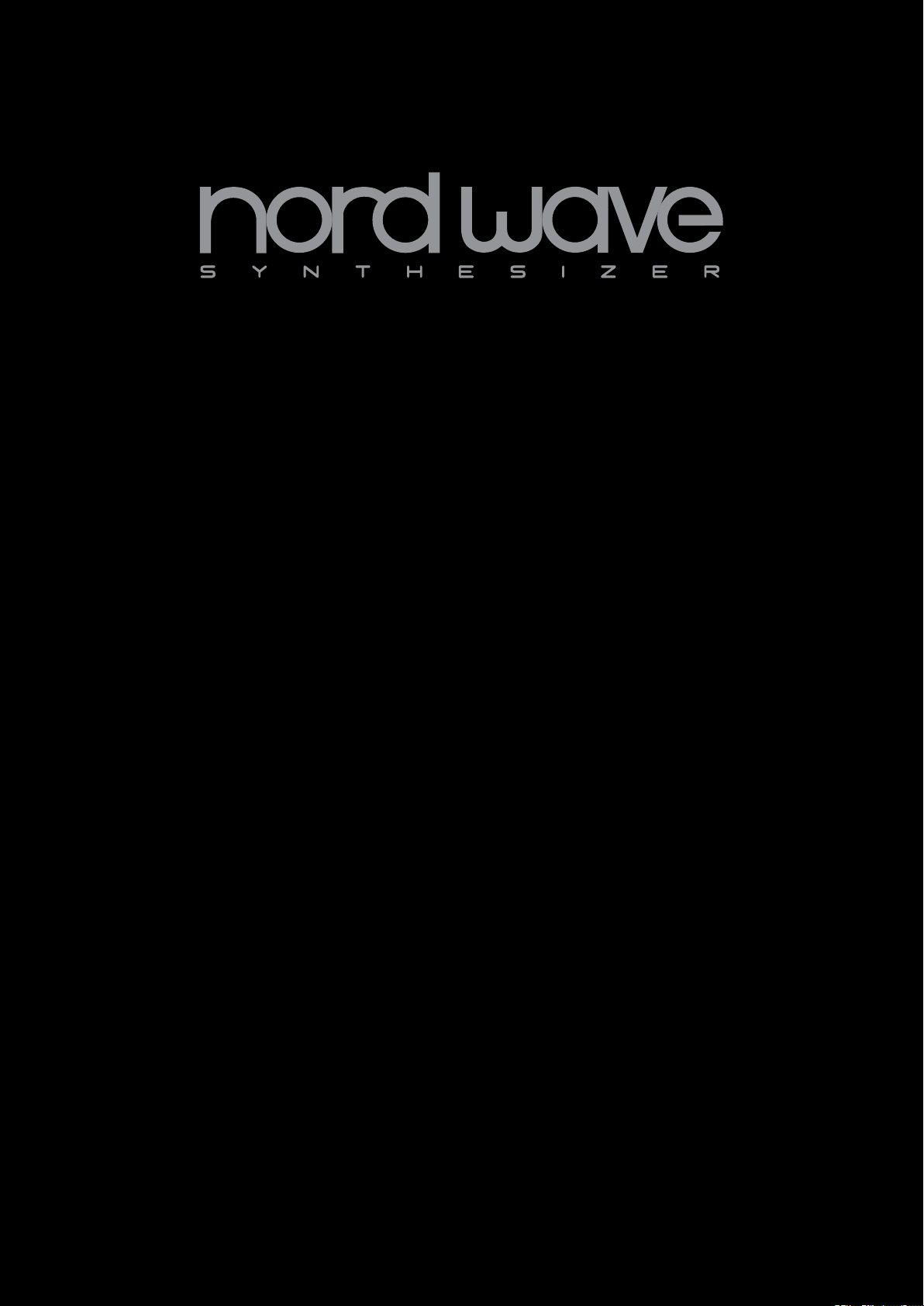
The Front Panel
The front panel on the Nord Wave has three main areas, which are
identified by their background color. We’ll familiarize ourselves briefly
with the panel here and describe the functions in detail in the following
chapters.
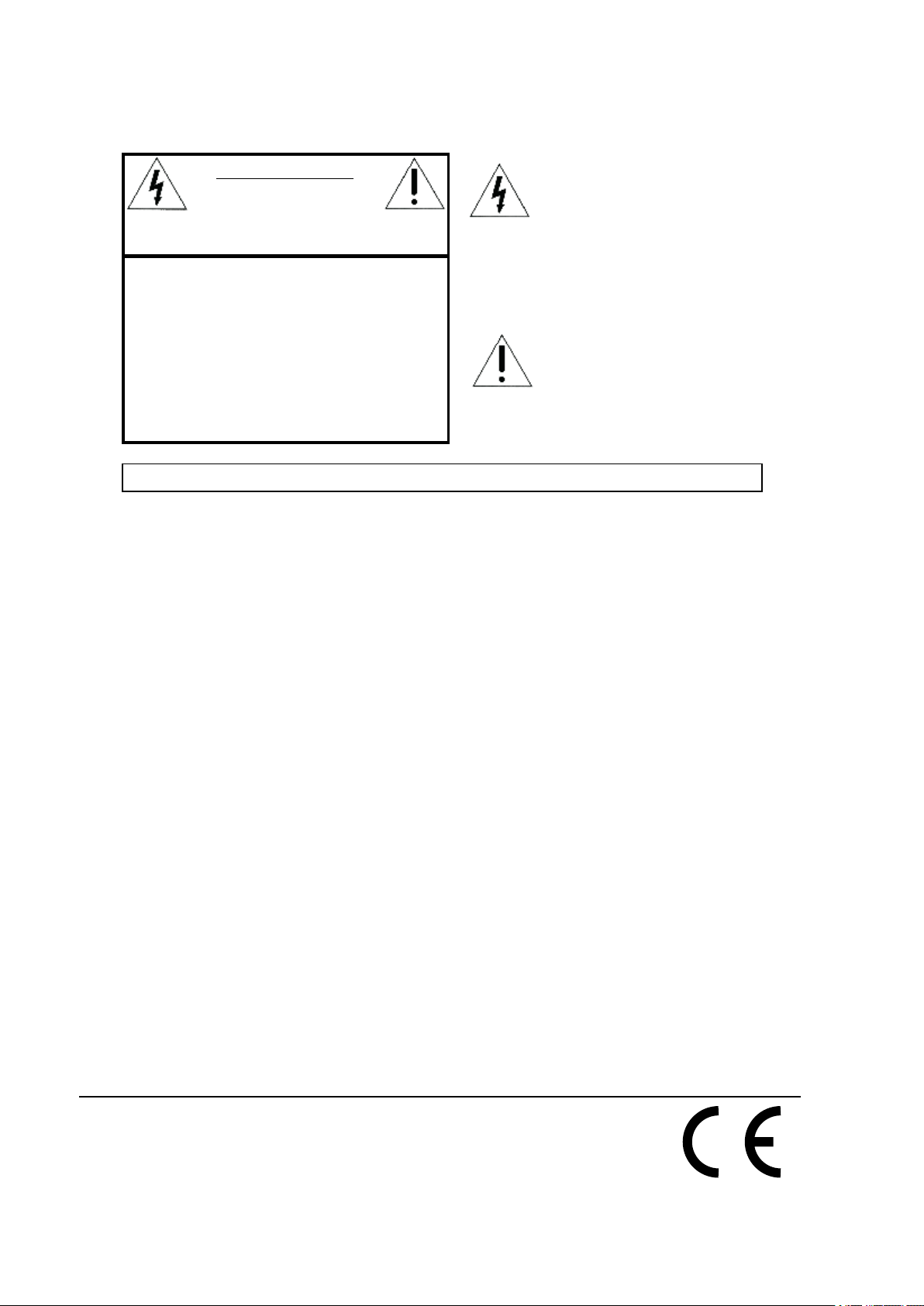
The parameters and functions in this area are used to select programs,
to set global and MIDI functions and to add expression to your performance with the Pitch Stick and the Mod Wheel. This is also where
you find the two Slot buttons, which you use to activate one or both of
the Nord Wave synth engines.
We’ll describe the functions in this area in greater detail, starting at
page 15.
Synth area
The synth area is where all the action happens. Every vital, sound
generating function in the Nord Wave has a dedicated knob or button,
and they are all there for you to go ahead and get crazy, to design the
sound as you wish.
Each program in the Nord Wave contains two individual synth engines.
Both are controlled through the same panel, one at a time. You choose
which section to control by pressing the Slot A or Slot B button.
We’ll describe the functions in this area in greater detail, starting at
page 18.
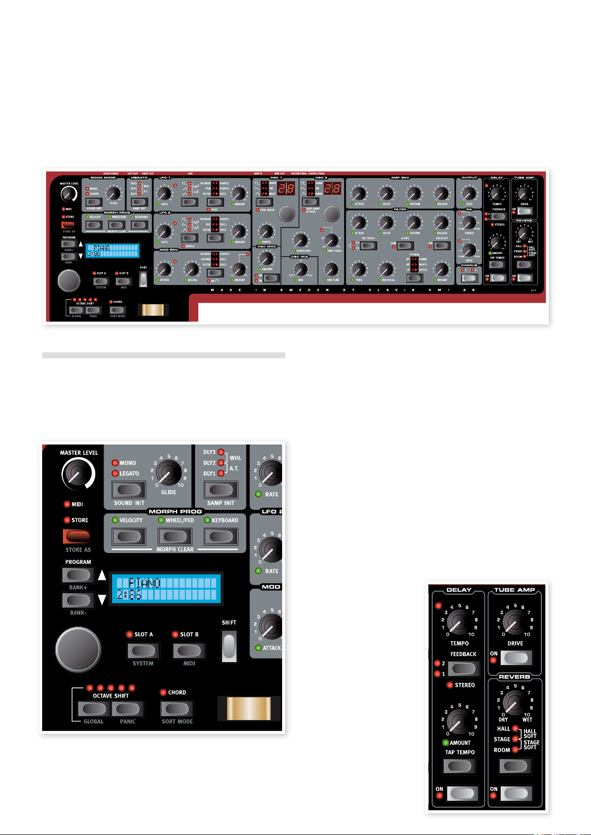
Effect area
The Effect area contains the
parameters used for editing
the program specific effect
parameters. The functions here
are common for both slots.
Please refer to page 31 for more
information.
Program & Performance area
The Program and Performance area starts at the Master Volume
in the top left panel corner, and then sweeps down right towards the
keyboard.
Page 8
8 | NordWaveUserMaNUalv2.x
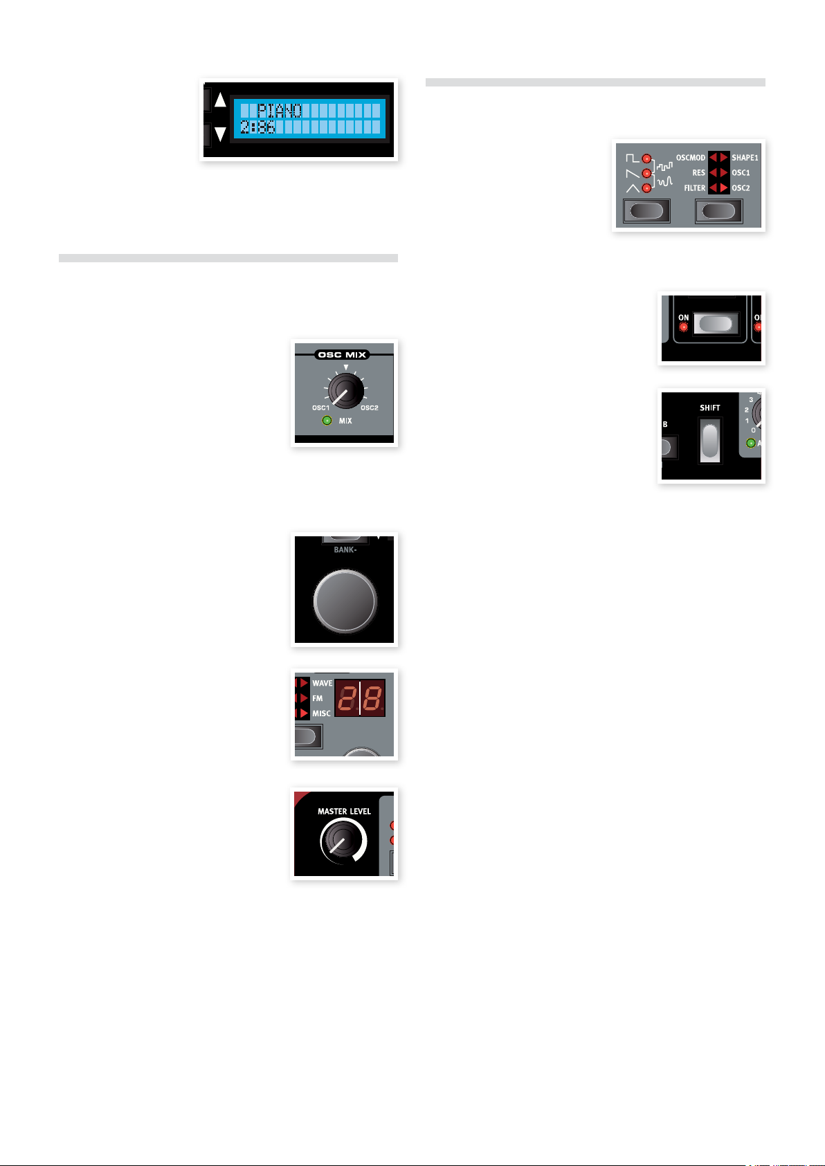
LCD
The LCD is normally used
for displaying the current
program bank, number,
name and category.
When operating a knob or button, the associated parameter name and
setting will be displayed in the LCD.
Buttons
Selector buttons
Selector buttons are used to
activate one setting in an array of
two or more. Selector buttons have
a set of round or triangular LEDs to
indicate the current setting. Press
the button several times to cycle through the possible options.
Knobs & dials
Knobs
The knobs controls the continuously variable
parameters in the Nord Wave synth engine.
A parameter value can be totally different •
from the knob’s physical position when you
load a Program. As soon as you start turning the knob, the value will ‘snap’ to the
knob’s physical position.
Most of the knobs have a green LED indicator below them. This LED is
used for indicating when a parameter is connected to a Morph source.
Please refer to page 13 for more information on morphing.
The Rotary dial
The Rotary dial is used for changing the
current setting displayed in the LCD. Usually
this means loading a new program, but in the
System or MIDI menus, the Rotary is used
to change parameter settings.
LED-dials
These dials in the oscillator section have an
associated LED display which shows their
parameter setting. They are used to select
wavetables or Sample Instruments.
On/Off buttons
On/Off buttons are used for activating a
parameter or a group of parameters such
as effects.
Shift button
Some buttons have a secondary function,
which will be available if you hold down
Shift while pressing the button. The name
of the secondary function is printed below
the button.
Master Level knob
The Master Level knob controls the overall
amplitude for the audio outputs, the line level
outputs and headphone output. The Master
Level knob’s actual position indicates the
output level.
Page 9
3coNNectIoNs | 9
Connections
3
Audio Connections
Left out and right out
The left and right line level outputs from the Nord Wave are unbalanced. Use 1/4" connectors to connect the Nord Wave to an amplifier
or recording equipment.
The Nord Wave is a true stereo instrument, with separate signal paths
for the left and right audio channels. To properly experience the Nord
Wave, always use both outputs in a stereo operation.
Headphones
This is where you connect a 1/4" stereo connector from a pair of
headphones.
General guide on audio connections
Make all the connections before you turn on the power to your amplifier.•
Turn • on the power to your amplifier last.
Turn • off the power to your amplifier first.
Playing at a high volume level can result in hearing impairments E
such as permanent hearing loss.
USB Connection
The USB connection is used for the Nord Wave to communicate with
a personal computer. The computer can e.g. run the Nord Sound
Manager application, the Sample Editor application, or be used if the
operating system in the synthesizer needs to be updated.
Computers running Microsoft Windows operating systems need a E
driver for the USB connection to function. The driver can be found
on the enclosed Nord Wave DVD, or at the Nord web site.
Pedal Connections
The Nord Wave has two pedal inputs; one for a sustain pedal and one
for a control pedal (an expression type pedal, which can be used to
control various parameters).
Sustain pedal
1/4" connector for a switch type pedal. When a connected pedal is
operated, the notes you play will be sustained.
Two types of pedal polarities can be used, you select the one that applies to your sustain pedal, in the System menu which is described on
page 59.
MIDI Connections
MIDI OUT
MIDI connection used for sending MIDI data from the Nord Wave to
other equipment such as sound modules or computers.
MIDI IN
MIDI connection used to receive MIDI data to the Nord Wave from
other equipment such as keyboards, sound modules and computers.
Control pedal
1/4" stereo connector for pedals of potentiometer type (also know as
expression pedals). This can be used as a source for the Morph function or to control the overall volume. Please refer to page 13 for more
information on Morphing.
When connecting an expression pedal to the Control Pedal input, you
should use a stereo cable (Tip-Ring-Sleeve). Please note that the pedal
must have a stereo output jack. The resistance range of the Control
Pedal should be 10 or 50 kOhm.
To simplify setup, the most common pedal models (Roland, Yamaha,
Ernie Ball and Fatar) are pre-configured in the Nord Wave, and you simply select the type of pedal which you want to use in the System menu.
The System Menu is described on page 59.
Page 10
10 | NordWaveUserMaNUalv2.x
Getting Started
4
About Programs
Complete sound settings are stored in the Program memory of the
Nord Wave. This memory area consists of 8 Banks with 128 Programs
each which makes a grand total of 1024 Programs. Every Program
can be edited and replaced as you wish. A complete set of the factory
Programs are available on the Nord Wave DVD and on our website.
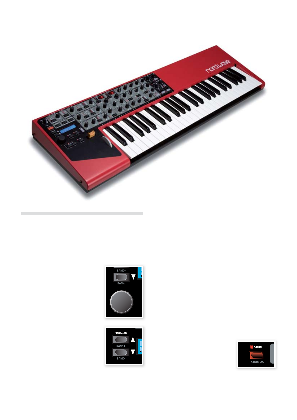
Select a Program
Use the 1 ROTARY DIAL to select a
Program.
To switch between 2 Banks, press and
hold Shift and then the Up/Down
buttons that is located to the left of the
LCD.
The Bank is indicated by the single digit
to the left and the program number by
the digits to the right in the LCD. Each
Program has a name and they are also
categorized in 17 different categories.
3
If you reach the last or the first Program
in a Bank, you can switch to the next
bank by pressing the Up or the Down
button.
It’s also possible to browse or select Programs by Category or in an •
alphabetical order. This is described in detail in the Sort Mode section
on page 18.
Edit a Program
Editing a Program is just as easy as grabbing a knob and change a
setting, or press a button to select a different setting. The knobs physical position isn’t always as the setting in the Program that is active,
but as soon as you start turning a knob, the parameter will snap to the
knob’s position.
1 Filter Freq knob.
Turn e.g. the
The parameter value will be shown briefly in the LCD.
When you have edited a Program, an asterisk (*) will appear in the LCD
next to the Program number to alert you to the fact that the program
has been edited but not yet saved.
If you select a new program without saving, any edits you have made
will be lost and the Program will have its original settings the next time
you select it.
Saving a Program
If you are happy with an edit that you have made, you should probably
save the Program.
Press the 1 Store button.
The Store button LED starts flashing and
the original Program location is shown in
the LCD.
There is a Memory Protect function that is •
set to On when the Wave leaves the Nord Factory. This needs to be
turned Off in the System Menu before you can save a Program.
2 Shift + System and scroll to the Memory Protect setting
Press
with the Up/Down buttons and set this to Off using the Rotary.
Page 11

4GettINGstarted | 11
Select a new location where you want to store the Program.3
Use the Up/Down buttons and/or the Rotary dial to choose a
new Program location if you do not want to overwrite the original
Program.
To select another bank, press Shift and select another bank with
the Up/Down buttons.
4 Store button a second time to confirm your choice.
Press the
Your edited Program has now replaced the previous one in the
location you specified.
To cancel the procedure, press any buttons on the panel before you •
press Store the second time.
With Memory Protect set to Off, a double tap on the • Store button
will store a Program in its original location.
Saving a Program with a new name and/or category
Press the 1 Store as button (Shift + Store).
The Store button LED starts flashing and the Program name and
category is shown in the LCD.
2 Rotary Dial to select a category.
Use the
Give your program a name using the Up/Down buttons to
change position, and the Rotary to scroll between the available
characters.
3 Store button a second time to confirm the new name
Press the
and category selection.
Use the 4 Up/Down buttons or the Rotary dial to choose the loca-
tion where you want to store the Program.
Layering
To play with both the slots in a selected Program is called to layer two
sounds.
1
Press both of the Slot buttons at the same time.
One slot LED will be steadily lit, the other will flash. This indicates
which of the two slots has the Panel focus, more on this in a little
while.
Deactivating Slots
To deactivate a Slot in a layer, press both 1 Slot buttons, and then
release one of them.
The slot with the button you released will be the one that is removed from the layer.
Copying a setting from one Slot to another
In order to be able to organize the sounds to suit your needs, you can
copy settings from one slot to another.
1 Slot button.
Press and hold a
Turn the Rotary dial or press the Up/Down buttons to scroll
through the memory area.
2
When you have found the desired Slot and Program that you wish
to copy, release the Slot button.
The settings from the selected Slot and Program are now copied
to the Program/Slot in use.
If you want to keep these new settings, make sure that you save the •
Program before you select a new one.
5 Store button a third time to confirm your choice.
Press the
Your edited Program has now replaced the previous one in the
location you chose.
Slots
The Nord Wave has two Slots labelled A and B. Each slot represents a
complete synthesizer setup, a complete sound if you wish. The Slots
can be used for layering sounds or quickly switch between sound
settings. The Slots are also used when the Nord Wave is controlled via
MIDI.
Every Program contains the settings for each individual slot. Program
1:11 can have a piano sound setting for Slot A and a string setting for
slot B. You can very quickly switch between the two slots in a live situation by pressing a button. You can also layer the two slots, playing both
sounds from the keyboard at the same time.
Switch between two sounds
Select a Program. 1
Press repeatedly on the Slot A 2
and the Slot B buttons to activate
the two different sounds in that
particular Program.
Focus
To be able to fully take advantage of the flexibility of the two slots and
the knobs and buttons on the panel, the Nord Wave uses a concept
that we call Focus which means “active for”.
When you select a Program in the Wave and play on the keyboard with
e.g. Slot A active (its LED being lit), that Slot has the keyboard focus.
This means that you use the keyboard, pitch stick, morph functions
and other performance controls on the Wave to control it.
This slot also has the panel focus; a solitary slot always has both panel
and keyboard focus. If you grab a knob on the panel and turn it, the
sound will change.
If you select both slots to create a layer as described earlier, the slot
with the flashing LED will be the one with panel focus. Both slots will
have keyboard focus.
1
To switch the panel focus from one slot to the other in a layer, just
press the Slot button of the slot you wish to put in panel focus.
This makes it possible to play two sounds with the keyboard, and
edit one of them at a time with the panel controls.
The configuration of the two slots in a Program will be kept when a •
Program is saved. This includes the selection of the Panel Focus.
Page 12
12 | NordWaveUserMaNUalv2.x
Adding an effect
The Nord Wave has two different sets of effects. The two band EQ
and the chorus are Slot effects which mean they can be used with
individual settings for each one of the two slots in a Program.
The delay, the tube amp simulator and the reverb are the Program
effects, and they will process both the slots at the same time, if both
slots are active.
1
Dial up the Wurlitzer program, bank 1, number 30.
Play a few notes and notice the subtle reverb and the panning.
The panning effect is actually made with the LFO; turn down the
LFO1 AMOUNT knob if you want to turn this off.
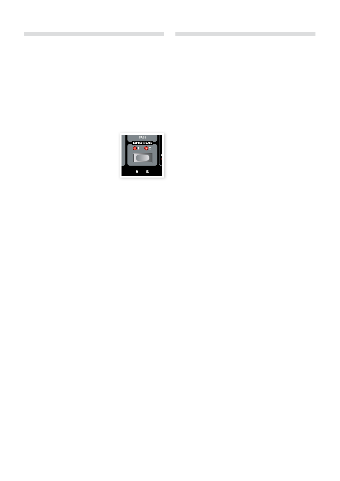
Press the
2 Chorus button once.
This adds a subtle chorus effect.
3 Chorus button again to select
Press the
the second chorus depth, and a third
time to select the third chorus depth.
If you find a sound to be to offensive in the
overall mix, try turning down the Bass EQ control a bit. The EQ is activated as soon as you turn an EQ knob from its 12 o’clock position.
4 Delay ON button to add a delay to the Wurly.
Press the
You set the level of the delay signal with the Amount knob and
the feedback by pressing repeatedly on the Feedback button.
5 Shift + Stereo in the delay section to get a stereo delay
Press
with a panning effect.
A quick MIDI Setup
The default MIDI Channel on the Wave is channel 1 for the transmission
of the keyboard and performance functions, and also for the reception
of note-on messages for both the two slots.
Every knob and button on the panel can send MIDI Control Change
messages. This makes it possible to record e.g. a filter sweep to a
sequencer.
Since the two slots combined have more knobs and buttons than the
MIDI specification has available CC addresses, the two slots can be set
to two separate MIDI transmission channels.
1 Shift + MIDI to enter the MIDI Menu.
Press
Use the Up/Down buttons to select the MIDI Channel function.
This sets the MIDI Channel that is being transmitted from the keyboard
and also being used as the receiving channel for both slots simultaneously.
2 Up/Down
Exit the MIDI Menu by pressing any button except the
buttons.
Controlling Slot A and B on separate MIDI Channels
The two slots may receive MIDI note messages on individual MIDI
channels, in the bi-timbral mode.
1 Shift and MIDI to enter the MIDI Menu.
Press
2 Up/Down buttons to navigate to the MIDI parameter.
Use the
Set this function to Bi-Timb.
This will not disconnect the Wave keyboard and performance con-•
trols from the Slots. If you want that kind of functionality, you also
have to set the Local function to Off.
3 Up/Down buttons to select the MIDI Ctrl A parameter and
Use the
set this to the MIDI channel that you want Slot A to respond to.
Use the 4 Up/Down buttons to select the MIDI Ctrl B parameter and
set this to the MIDI channel that you want Slot B to respond to.
5 Up/Down
Exit the MIDI Menu by pressing any button except the
buttons.
In the following sections you will find a chapter about the
powerful Morph function, a function reference, a chapter that
is totally devoted to the Nord Sound Manager, another that
explains the Nord Sample Editor application and also a chapter
that describes a bit what this “synthesis” thing is all about.
Page 13
5theMorPhFUNctIoN | 13
The Morph Function
5
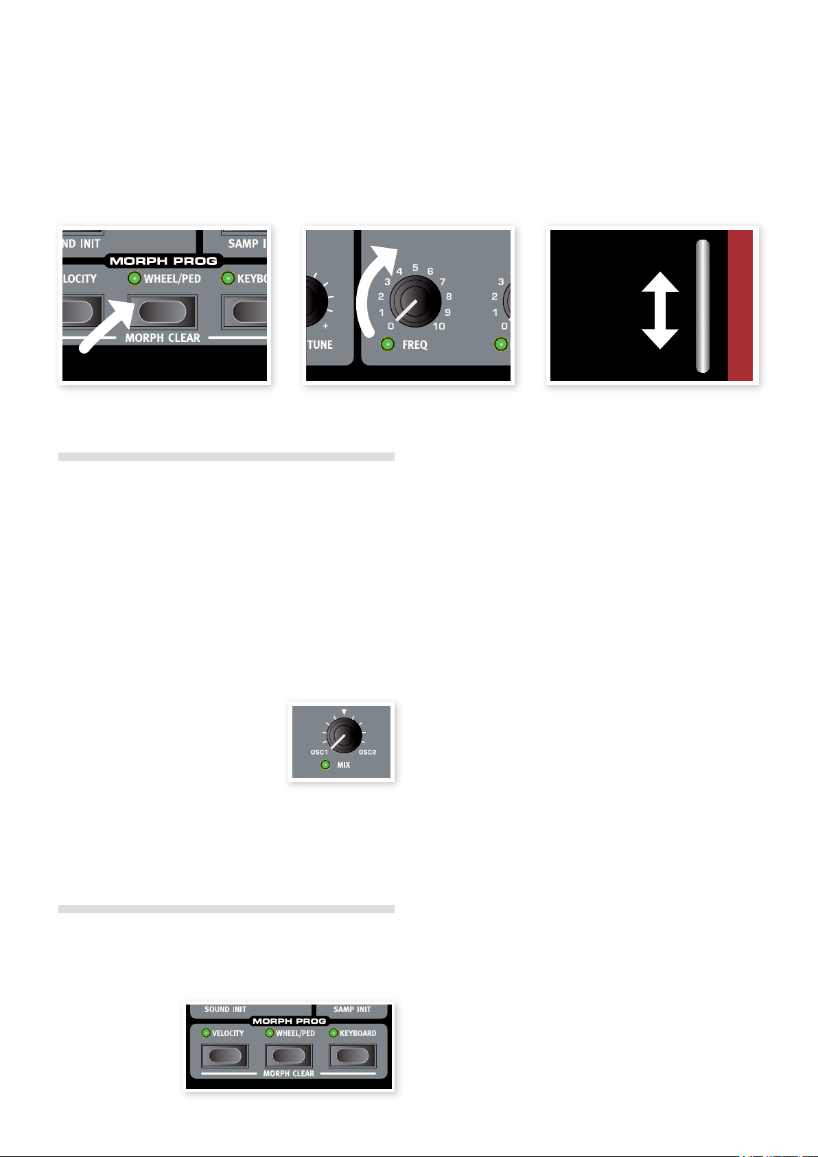
1. Press 2. Turn 3. Play and use the Mod Wheel
About Morphing
Morphing allows you to be very dynamic and creative in your sound design, and is all about being able to control virtually any important sound
related parameter from the Morph sources. These three sources are:
the Modulation Wheel & Control Pedal, the Keyboard and the Velocity.
There are 26 available Morph destinations to choose from. This gives
you plenty of real-time control possibilities to augment your playing
style. A Morph is very simple to set up and use, and all Morph assignments are stored with the Program.
Many of the factory Programs have morph assigned parameters. If a
Program uses Morph, one or more of the green Morph Prog
indicators on the panel will be lit to indicate this.
If e.g. the • Wheel indicator in the Morph
Prog section is lit for a Program, you can
move the wheel and experience how the
morph will influence the sound.
A Morph Source controls the range from the
parameter’s original position in the Program to
a position you define when you set up the morph.
This means that you can control a very small range on one parameter
at the same time as you control a very large range on a another parameter. One parameter can be controlled clockwise, and another can be
controlled counter clockwise.
A key velocity of 127 represents the parameters morphed value.•
Modulation Wheel and/or Control Pedal (Wheel/Ped)
Uses the modulation wheel and/or a pedal connected to the Control Pedal input as the Morph Source.
Incoming MIDI Control Change messages on CC 01 and CC
11will also act as a Wheel/Ped Morph source.
The bottom position of the • Modulation Wheel or Control Pedal
represents the parameters original value.
The top position of the • Modulation Wheel or Control Pedal
represents the parameters morphed value.
If the Control Pedal is set to control the overall volume of the Nord
Wave, in the System Menu, the wheel will be a solitary Morph
source when Wheel/Ped is selected.
Keyboard Note (Keyboard)
This sets the Keyboard Note Numbers as a Morph Source.
The bottom key of the • keyboard (C2) represents the parameters
original value.
The top key (C6) of the • keyboard represents the parameters mor-
phed value.
When using an external keyboard controller connected to the E
Nord Wave MIDI IN, or when the Wave keyboard has been transposed, any incoming notes outside of the keyboard range, will
morph the parameter until the parameters end position is reached.
Morph Sources
There are three Morph Sources available:
Note Velocity (Velocity)
This Morph source
uses the Note Velocity
from the Nord Wave
keyboard and from any
incoming MIDI messages.
A key velocity of 0 represents the parameters original value. •
Assign a Morph source to a destination
Hold down a 1 Morph Source button.
If this source has any previously assigned Morph destinations,
these destinations LEDs will light up.
2
Operate a Morph Destination parameter.
The selected Morph Destination’s green LED will indicate that a
Morph is active.
The LCD will indicate the parameters original value and the
3
Morphed value.
Page 14
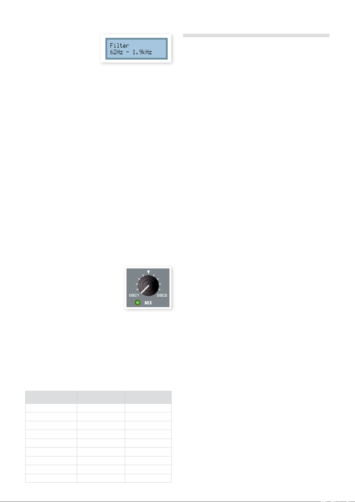
14 | NordWaveUserMaNUalv2.x
In this example the filter
cutoff will be Morphed from
its original setting of 62Hz to
1.9kHz during the full travel
or range of the Morph source.
4 Morph Source button.
Release the
When the Morph source is operated, the parameter’s value will
change accordingly and the sound will change.
To edit a morph range from a Morph Source:
Press the corresponding Morph Source button and turn the destina-•
tion’s knob to a new position.
To clear all morphs from a single Morph Source:
Press • Shift + the corresponding Morph Source button.
To clear a single Morph destination:
Hold down the corresponding Morph Source button and operate the •
parameter knob to its original position, where the Morph LED will be
turned off.
Morph Mode
Morph Mode provides you with a great overview that can simplify setting up and adjusting multiple Morph Destinations at once.
Morph Examples
New to morphing? No worries, let’s setup a Morph for one of the Factory Programs.
1
Select the Grand Piano, Program 1:2.
Press the Slot B button and hold it down, and then turn the Rotary 2
counter clock wise until you see FullStrings 1:1 A.
This will copy the string sound to Slot B for this little exercise.
Don’t activate Slot A just yet.
3
Press and hold Shift and then press Morph Velocity and also the
Morph Wheel buttons.
This will remove the Morph assignments in this string sound and
we can start with a clean slate.
Operate the Output Level knob all the way to the minimum value.
4
This will make the string sound silent, enabling us to be able to
use the Morph to bring it back up in amplitude again.
5
Double tap on the Morph Wheel button and turn up the Output
level to about 3.0.
The LCD will display the original setting of 0, and the Morphed
setting of 3.0. The Morph will be instantly available, play a few
notes and operate the Mod Wheel to hear the result.
1
Double-tap on one of the Morph Source buttons.
The Morph Source button flashes continuously, and the LEDs will
show any of the associated Morph Destinations.
2
Operate a Morph Destination parameter.
The selected Morph Destination’s green LED will indicate that a
Morph is active.
3
The LCD will indicate the parameters
original value and the Morphed value.
Press any of the Morph Source buttons
to exit Morph Mode.
When the Morph Mode is active you can:
Operate any • Morph Destination to set-up or adjust a morph.
Hold down the • Shift button and operate a Morph Destination to
clear it.
Morph Destinations
A Morph Source can control virtually any important sound related knob,
Each one of these Morph Destinations has a green LED next to it,
which will be lit when a Morph is active for this parameter.
Parameter name
LFO 1 Rate OSC MOD Amount FILTER Decay
LFO 1 Amount OSC MIX FILTER Sustain
LFO 2 Rate OSC SEMI TONES FILTER Release
LFO 2 Amount UNISON FILTER Freq
MOD ENV Attack AMP ENV Attack FILTER Res
MOD ENV Dec/Rel AMP ENV Decay FILTER Env Amt
MOD ENV Amount AMP ENV Sustain OUTPUT Level
OSC Shape 1 AMP ENV Release DELAY Amount
OSC Shape 2 FILTER Attack
Press both the Slot A and Slot B buttons to activate these two
6
sounds in a layer.
When you operate the Mod Wheel, the string sound will be gradually introduced in the layered sound.
You want more? Here is another example:
Dial up the Persian Santur Program, 1:41.
1
Play a few notes in the high, the middle and the low part of the
keyboard. Notice how the release is quite long in every area of the
keyboard.
Double tap on the Morph Keyboard button.2
Turn the Amplifier Release knob counter clock wise and set the 3
Morphed release to be about 250 ms.
You’ll notice that the release is long in the lower octave and gets
shorter the higher up on the keyboard you play.
Press the Morph Keyboard button again to exit the Morph Mode.
The LFO2 doesn’t do anything in this Program so let’s give it some work.
Select OSC2 for the LFO2 Destination.
4
Make sure that the triangle waveform is selected to the LFO2.
5
Set the LFO rate to about 3-4 Hz and the amount to 0.
This will not produce any noticeable modulation on the sound but
wait, we are not done yet.
6
Press Shift and LFO2 Single to set the LFO to single mode.
The LFO will now run through one single cycle, acting like an
envelope.
7
Double tap on the Morph Velocity button.
Turn up the LFO2 amount to about 4.8
When you play with a bit of force, the velocity will Morph the LFO2
Amount, and the pitch of the sound will change according to the
one cycle the LFO will produce.
Page 15
6NordWavereFereNce | 15
Nord Wave Reference
6
Saving a Program with a new name and/or
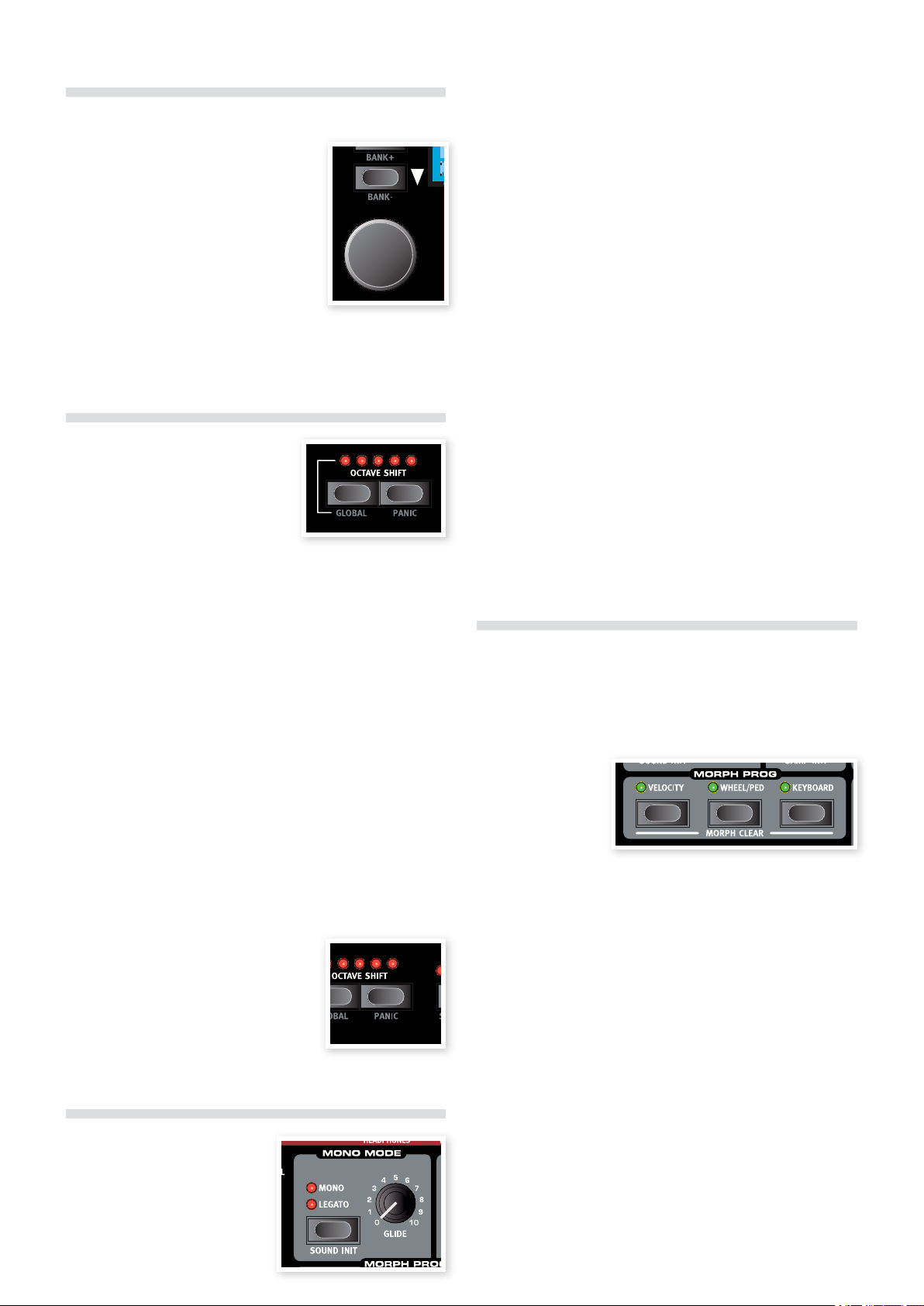
Master Level knob
The Master Level knob controls the overall
amplitude for the audio outputs - the line
level outputs and the headphone output.
The Master Level knob’s actual position
indicates the output level. This is one of the
very few functions in the Nord Wave that is
not stored in a Program.
category
Press the 1 Store As button (Shift + Store)
The Store button LED starts flashing and the Program name and
category is shown in the LCD.
2 Rotary Dial to select a category.
Use the
There are 17 categories to chose from. Look at page 18 for a
complete list.
MIDI LED indicator
The MIDI LED will indicate incoming MIDI
note messages by briefly lighting up.
If the incoming messages are on a MIDI •
channel that the Nord Wave is not responding to, these indications
will be short. If the incoming MIDI channels matches the channel(s)
you select in the System menu, the indications will be longer.
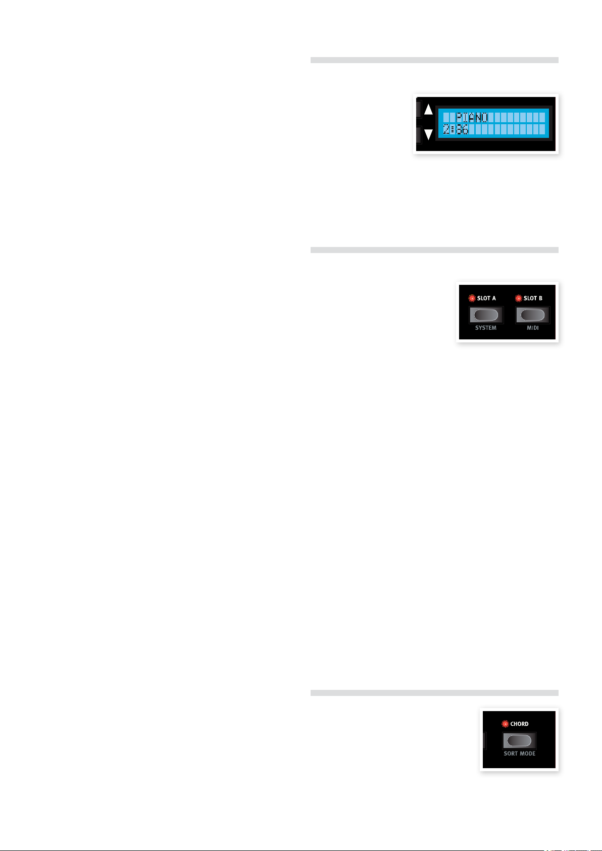
Store Button
The Store button is used when you wish to
store a Program in the Program memory on
the Nord Wave. During the process, you will
get the opportunity to select a location where
you want to store the Program.
This button’s secondary function Store As can be used if you wish to
change the name of a Program or the category.
1 Store button.
Press the
The Store button LED starts flashing and the original Program
location is shown in the LCD.
There is a Memory Protect function that may need to be turned Off •
in the System Menu before you can save a Program. Press Shift +
System and scroll to the Memory Protect setting with the Up/Down
Navigator buttons and set this to Off using the Rotary Dial.
2
Select a new location.
Use the Program buttons and/or the Rotary Dial to choose a
new Program location if you do not want to overwrite the original
Program. To select another bank, press Shift and the Up/Down
Navigator buttons.
Press the
3 Store button a second time to confirm your choice.
The Store LED stops flashing and your Program has now replaced
the previous one in the location you selected.
3 Up/Down buttons to
Give your program a name using the
change position, and the Rotary to scroll between the available
characters.
4 Store button a second time to confirm the new name
Press the
and category selection.
Use the 5 Program buttons or the Rotary dial to choose the loca-
tion where you want to store the Program.
6 Store button a third time to confirm your choice.
Press the
The Store LED stops flashing and your edited Program has now
replaced the previous one in the location you chose.
To cancel the procedure, press any button on the panel before you •
press Store the third time.
Program Up/Down buttons
The Up/Down buttons allows you to select
Programs. Depending on the selected Sort
Mode, you may step through consecutive
numbers in the Banks, step through the Programs in a selected category or step through
the Programs in an alphabetical order.
If you press and hold any of these buttons, •
Programs will be selected in a rapid and
consecutive order.
If you press and hold Shift, these buttons allows you to change Banks,
change Category or initial character, depending on the Sort Mode.
Read more about the Sort Mode on page 18.
When you have reached the last Program in a Bank, Category or •
alphabetical list, pressing Up will select the next available Program in
the next Bank, Category or alphabetical list.
If a Bank contains empty memory locations, these will not be dis-
played when you scroll through the Banks. They will however be
displayed when you browse for a location to save a Program.
To cancel the procedure, press any button on the panel before you •
press Store the second time.
Page 16
16 | NordWaveUserMaNUalv2.x
Rotary Dial
The Rotary dial is used for changing the
current setting displayed in the LCD. Usually
this means loading a new program, but in the
System or MIDI menus, the Rotary is used to
change parameter settings.
The dial is endless, though the array of parameter settings are not. Once you reach the first
or last possible setting, turning the dial further
will have no effect.
The Rotary has an accelerator feature; when operated swiftly you
scroll through the values in larger intervals.
Mono Mode button
There are two available mono modes. These differ in how the envelopes are triggered if you press a key without releasing the previous
one.
The • Mono setting will re-trigger the envelopes; the sound will “re-
start” for each note you play.
The • Legato setting will not re-trigger the envelopes; the sound will
“continue” with only a change in pitch.
Sound Init
By pressing the Sound Init button (Shift + Mono Mode buttons),
the settings of the Slot in focus will be initialized. This provides you with
a neutral starting point if you want to program a sound from scratch.
The settings of the oscillator waveforms, oscillator mix and the pro-•
gram effects will be excluded from the initialization. The effects will be
turned off for the Slot but the actual settings will not be changed.
Octave Shift buttons
The Octave Shift buttons transposes
the sound of the Slot that has the Panel
Focus.
Range: -24. -12, 0, +12, +24
The center LED indicates when no octave shift is applied.
LEDs to the right of the center LED will indicate a higher octave shift •
as you press the right Octave Shift button.
LEDs to the left of the center LED will indicate a lower octave shift as •
you press the left Octave Shift button.
Messages from the Nord Wave’s MIDI Out will not be affected.
Global Octave
By pressing the Global button (Shift + Octave Shift down) you can
transpose the keyboard in even octaves. The LEDs will be in a inverted
state to indicate that you are in the Global Octave Shift mode.
In this mode, both Slots as well as the note messages from the MIDI •
output will be effected.
A combination of extreme E Octave Shift and OSC 2’s Semi
Tone setting can produce sounds that are outside the hearing
range.
Glide knob
If you press a key without releasing the previous one, the Glide parameter can be used to set the time interval for the pitch to glide from
the previous note, to the new note. With a setting of zero the pitch will
change instantly.
Range: 0 - 10.0
Morph Buttons
These are the buttons that you use to select the Morph sources when
you set up a Morph - Velocity, Wheel/Ped and Keyboard.
Note Velocity (Velocity)
This Morph source
use the Note Velocity
from the Nord Wave
keyboard and from
any incoming MIDI
messages.
A key velocity of 0 represents the parameters original value. •
A key velocity of 127 represents the parameters morphed value.•
Panic
By pressing the Panic button (Shift + Octave
shift up buttons) any voices that are producing
a sound on the Nord Wave will be silenced.
Equipment connected via MIDI Out will
not be affected.
Mono Mode
The Nord Wave is a polyphonic
instrument with 18 stereo voices. If
the Mono Mode is activated, it will
behave as a monophonic synthesizer. Only one key will produce a
sound at any time.
Modulation Wheel and/or Control Pedal (Wheel/Ped)
Uses the modulation wheel and/or a pedal connected to the Control Pedal input as the Morph Source.
Incoming MIDI Control Change messages on CC 01 and CC11
will also act as a Wheel/Ped Morph source.
The bottom position of the • Modulation Wheel or Control Pedal
represents the parameters original value.
The top position of the • Modulation Wheel or Control Pedal
represents the parameters morphed value.
Keyboard Note (Keyboard)
This sets the Keyboard Note Numbers as a Morph Source.
The bottom key of the • keyboard represents the parameters original
value.
The top key of the • keyboard represents the para meters morphed
value.
Page 17
6NordWavereFereNce | 17
The top and bottom keys of the Nord Wave keyboard are always
used as the reference, regardless of the octave shift and global
octave shift settings.
LCD Window
When using an external keyboard controller connected to the E
Nord Wave MIDI IN, any received notes outside of the keyboard
range, will morph the parameter, until the parameters end position
is reached.
For a detailed description on how to set up a Morph scenario, please
go to page 13.
Assign a Morph source to a destination
Hold down a 1 Morph Source button.
If this source has any previously assigned Morph destinations,
these destinations LEDs will light up.
2
Operate a Morph Destination parameter.
The selected Morph Destination’s LED will indicate that a Morph
is active.
The LCD will indicate the parameters original value and the Mor-
3
phed value.
The physical position of a knob may prevent you from adjusting this •
in a desired manner, e.g. if the knob is at the 0 position and you want
a negative Morph. In these cases, adjust the knob to a more suitable
position, reload the Program and set up the Morph again.
4 Morph Source button.
Release the
When the Morph source is operated, the parameter’s value will
change accordingly.
To edit a morph range from a Morph Source:
Press the corresponding Morph Source button and turn the destina-•
tion’s knob to a new position.
To clear all morphs from a single Morph Source:
Press • Shift + the corresponding Morph Source button.
To clear a single Morph destination:
Hold down the corresponding Morph Source button and operate the •
Morph Destination knob to its original position, where the Morph
LED will be turned off.
Morph Mode
Morph Mode provides you with a great overview that can simplify setting up and adjusting multiple Morph Destinations at once.
1
Double-tap one of the Morph Source buttons.
The Morph Source button flashes continuously, and all LEDs are
unlit, with the exception of the Morph Destinations that are associated with this source.
The LCD is normally used
for displaying the current
program bank, number,
name and category.
When you turn a knob or
press a button the associated parameter name and setting will be briefly displayed in the LCD.
The LCD is also used to display the functions in the System and MIDI
menus.
Slot Buttons
Every Program in the Nord Wave stores
the settings of two individual synthesizer setups, called Slots. This means
that you can quickly change from one
sound in Slot A to another sound in
Slot B, or to play with the sounds from
both slots at the same time in a layer.
The Slot buttons are used to select which one of these two sounds
should be controlled from the keyboard. To select both slots at the
same time, press both Slot buttons at the same time. A slot that is
controlled from the keyboard and other performance controls on the
Wave has the Keyboard Focus. Either one or both slots can be set to
Keyboard Focus.
The Slot Buttons are also used to select which of the two slots should
be active on the panel for editing purposes. This is called the Panel
Focus, and only one Slot at a time can have the Panel Focus. If two
Slots have the Keyboard focus, the slot with the flashing LED has the
Panel focus. Press either Slot button to shift the Panel focus from one
slot to the other.
System button
Press Shift and Slot A to enter the System Menu. The System Menu
is used for editing system specific settings, these are shown in the
LCD. The System Menu is described on page 59.
MIDI button
Press Shift and Slot B to enter the MIDI Menu. The MIDI Menu is
used for editing MIDI specific settings, which are shown in the LCD.
The MIDI Menu is described on page 60.
Press any of the Morph Source buttons to exit Morph Mode.
When the Morph Mode is active you can:
Operate any • Morph Destination to set-up or adjust a morph.
Hold down the • SHIFT button and operate a Morph Destination
to clear it.
Chord Button
The chord button is used to activate the
Chord Memory function. This can be used for
memorizing note intervals and automatically
adding them to the key(s) you play.
The Chord Memory settings are stored within a Program.
Page 18
18 | NordWaveUserMaNUalv2.x
Numerical sort order
Category sort order
Alphabetical sort order
Activating a Chord Memory
Play a chord and press & hold the
1 Chord button.
The display will show the numerical intervals of the notes in the
0
chord from the lowest note (which is displayed as
The three lowest keys in the chord will be memorized.
Release the
2 Chord button first, then the chord.
The note intervals are memorized and the Chord Memory function
is activated.
The intervals stored in the Chord Memory will be added automatically
to each note you play.
Deactivating a Chord Memory
Press the
1 Chord button to deactivate the Chord Memory func-
tion.
Once deactivated, you can at any time press the chord button
again (without holding any keys down) to re-activate it with the
previous chord memory setting.
Since you use several notes in the Chord Memory function, the E
polyphony will be reduced.
Only the actual key(s) you play will output MIDI Note information -
not the intervals included in the Chord Memory.
).
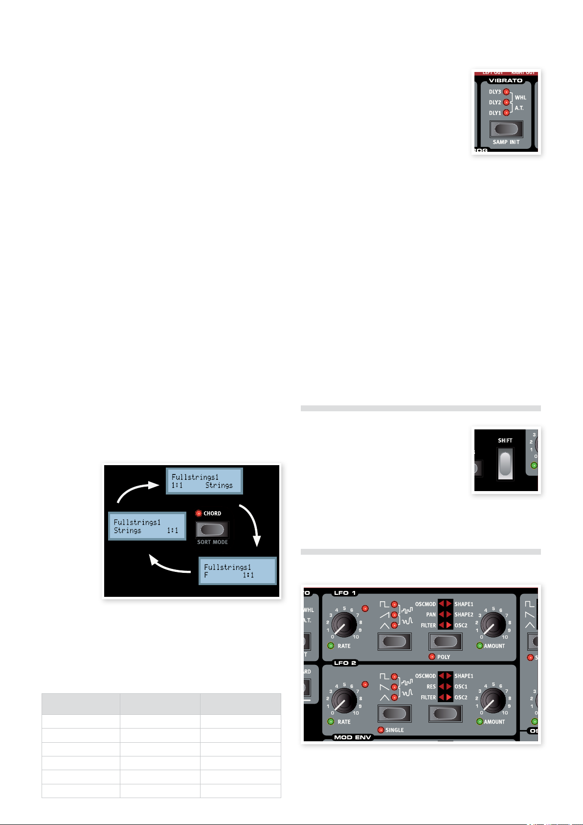
Sort Mode
The Nord Wave allows you to browse for (and load) Program in three
different Sort modes. By default, you load a Program by first selecting
the Bank with the Up/Down buttons and then turning the Rotary. The
Programs are then displayed (and activated) in a numerical order.
You can also set the Sort mode to be alphabetical or by Category. This
selection is made by pressing the Sort Mode button (Shift + Chord)
repeatedly.
If the Sort
mode is set to
numerical (/
alphabetical),
pressing the
Up/Down buttons or scrolling the Rotary
will select the
Programs in
a numerical
(by category/
alphabetical) fashion.
Vibrato
The vibrato function allows you to gradually
introduce subtle to dramatic changes in pitch as
you play. Press the vibrato button repeatedly to
select the desired vibrato functionality.
The • DLY1-3 setting will create a delayed
vibrato. The time interval ranges from short
to long.
The • a.t. setting will introduce the vibrato as you apply after touch on
the keyboard (or via MIDI).
The • Wheel setting will introduce vibrato as you operate the Modu-
lation Wheel.
The vibrato rate can be set in the System Menu.
SAMP Init
By pressing the SAMP Init button (Shift + Vibrato buttons), the settings of the Slot in focus will be initialized and the initialized settings for
the selected Sample Instrument in the Program will be activated.
This provides you with a neutral starting point if you want to program
a sound from scratch, using the settings that the Sample Instrument
creator has applied to the SI. Read more about this on page 51.
The settings of the program effects will be excluded from the •
initialization. The effects will be turned off for the Slot but the actual
settings will not be changed.
Shift Button
The Shift button is used together with other
buttons to access secondary functions. The
name of these functions are printed below the
buttons.
These functions are described together with
the primary functions of the buttons in this manual.
LFOs (LFO1 & LFO2)
When you have reached the first or last Program in a sort criteria, and
continue to scroll with the Up/Down buttons, the following Program
will be selected. To change Banks, press Shift and the Up/Down
buttons.
List of Categories
Categories
Acoustic Organ Vocal
Bass Pad Wind
Drum Piano User1
wFantasy Pluck User2
Fx Strings User3
Lead Synth
The LFO is a Low Frequency Oscillator. An LFO is an oscillator producing waveforms just like an ordinary oscillator, but with a few differences:
Page 19
6NordWavereFereNce | 19
The LFOs are capable of producing waveforms with a very low •
frequency.
LFOs are normally not used for generating audible frequencies. •
Instead the output from the LFO is used for modulating, that is controlling, other functions, like for example the main oscillator frequency
(vibrato) or the filter frequency.
The Nord Wave has separate LFOs for each voice, each LFO group (1
& 2) are in fact 18 separate LFOs.
You can sync them to act as a single LFO for all voices if you like. The
Nord Wave LFO 2 can also be used in a single-cycle mode, acting like
a simple Envelope Generator.
There are two LFOs available, with slightly different features.
Rate knob
The Rate knob is used to set the frequency of the LFO.
Range: 0.03 to 523 Hz
The LED to the upper right of the Rate knob indicates the rate for each
of the LFOs of the 18 voices. This means that when you play several
notes after one another, it’s the rate of the currently triggered LFO that
will be indicated.
Waveform Selector
The Waveform Selector button determines the waveform that is generated by the LFO.
Waveform Description
Square
Used for abrupt modulation changes, suitable for trills, distinct tremolos, etc.
Sawtooth
Used for ramp type modulations.
Inverted Sawtooth
Used for inverted ramp type modulations.
Triangle
Suitable for natural vibrato effects and also
used for classic pulse width modulation.
Stepped Random
Creates an abrupt modulation with random intensity.
Smooth Random
Creates a smooth random modulation.
LFO1 LFO2
a a
a
a
a a
a a
a a
LFO Destination Selector
The LFO Destination determines which parameter(s) the LFO will
modulate.
Destination Description
Filter Modulates the Filter Frequency parameter.
Res Modulates the Filter Resonance param-
eter.
Pan Modulates the position of the sound in the
stereo panorama.
OSC MOD Modulates the Oscillator Modulation
Amount.
Shape Modulates the Oscillator Shape parameter.
OSC1 Modulates the pitch of Oscillator 1.
OSC2 Modulates the pitch of Oscillator 2.
LFO1 LFO2
a a
a
a
a a
a a
a a
a a
If you press and hold the Destination selector, the modulation
will be muted - the indicators will start to flash to indicate this
state. Press again to reinstate the modulation.
Amount knob
This is used to set to what extent the signal from the LFO should affect
the selected destination.
Range: 0 to 10
Poly mode
In Poly mode, each individual voice will be affected by its own LFO.
Poly mode is activated by pressing the poly button (shift + LFO Destination button). This mode is available to LFO 1 only.
When Poly is not activated, the LFOs will be synchronized to each •
other.
Single mode
With single mode activated, the LFO plays a single cycle waveform
once without repeating. Single mode is available to LFO 2 only.
The Single Mode is also a polyphonic mode, each voice will have its •
own independent LFO.
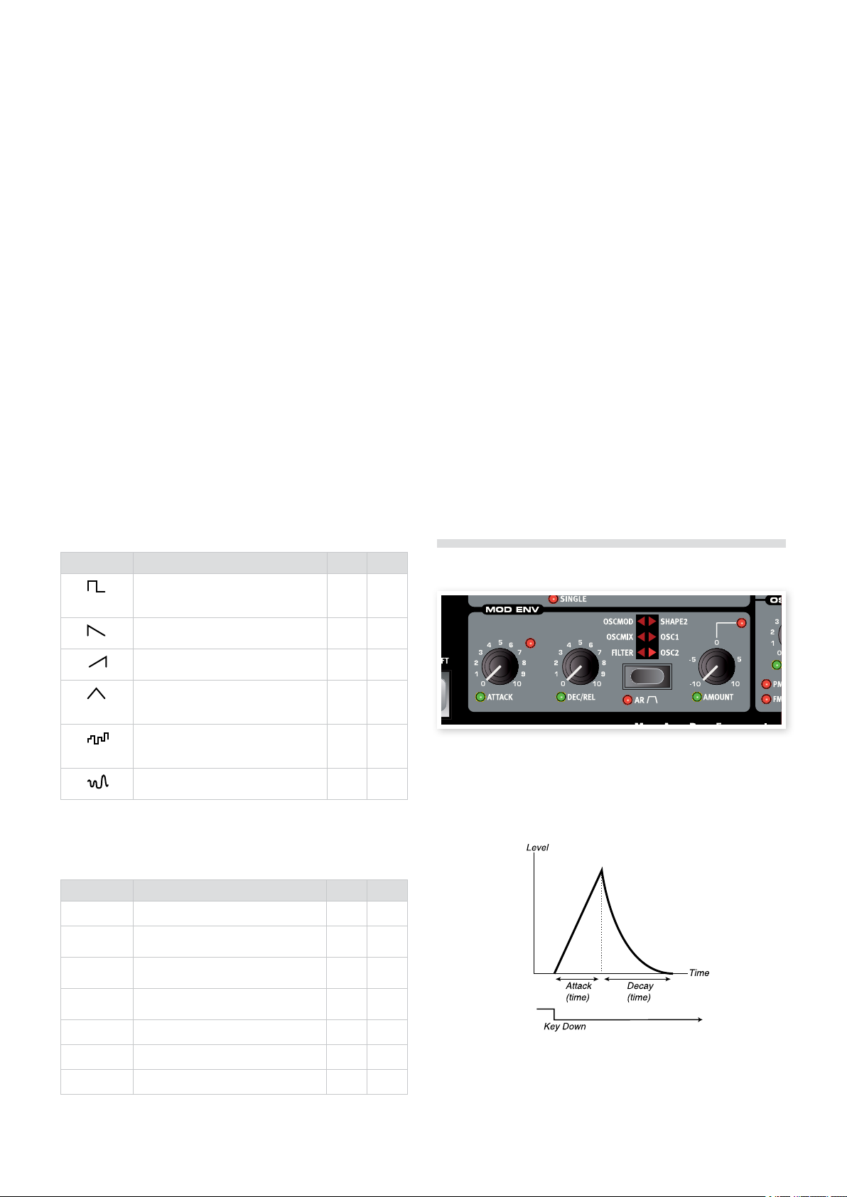
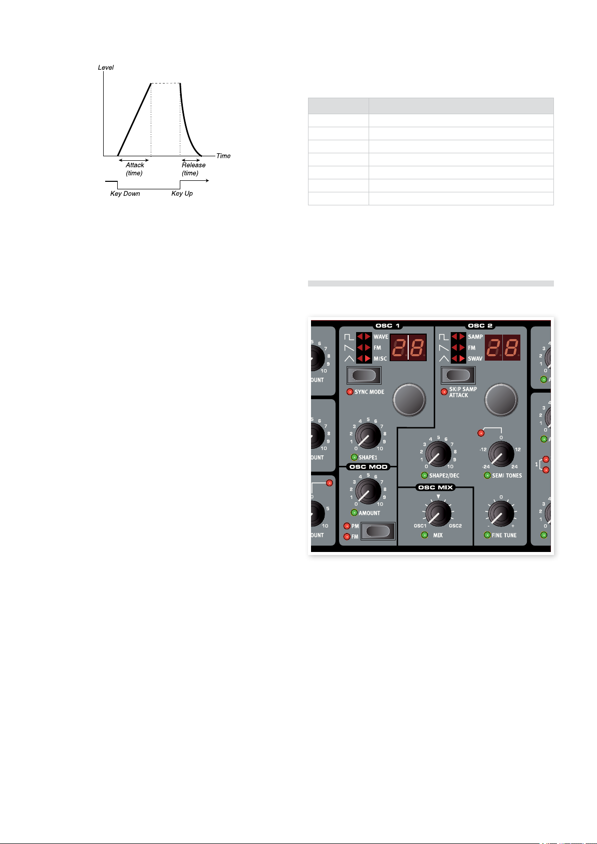
Modulation Envelope (MOD ENV)
The Modulation Envelope is an envelope with Attack, Decay/Release
and Amount controls. It sends out a control signal that can be used to
modulate various destinations in the Nord Wave. The modulation from
the envelope can be both positive or negative, this is determined with
the Mod Env Amount knob.
The image above illustrates the Modulation Envelope with Attack and
Decay parameters.
Press the Destination selector repeatedly to select the desired destination. The Shape 1 and Shape 2 for the LFO 1 can be selected at the
same time, as well as the Osc 1 and Osc 2 for the LFO 2.
Page 20
20 | NordWaveUserMaNUalv2.x
Destination selector
The Destination selector button selects the destination of the modulation. Press repeatedly to cycle through the various options.
Panel Description
Filter The Filter Frequency parameter
OSCMIX The Oscillator Mix parameter
OSCMOD The Oscillator Modulation Amount parameter
Shape2 The Shape parameter of oscillator 2
OSC1 The pitch of oscillator 1
OSC2 The pitch of oscillator 2
OSC1 + OSC2 The pitch of both oscillators
The image above illustrates the Modulation Envelope with Attack and
Release parameters.
The zero level of the Mod Envelope relates to the current setting of •
the selected target parameter. The maximum modulation amount
spans to the intensity set by the Mod Env Amt knob.
Attack knob
The Attack knob sets the time it should take for the envelope to reach
the maximum modulation level after you have pressed a key.
Range: 0.45 ms to 45 s
DEC/REL knob
Sets the decay or the release time of the envelope, depending on
whether the Mod Env is set to the AD or the AR mode.
Range: 3.0 ms to 45 s
AR button (Shift + Destination Select button)
The AR button toggles between the Attack/Decay or the Attack/Release mode:
AR setting disabled
The Dec/Rel knob controls the Decay time of the envelope. This is the
time that it takes for the envelope to fall back to zero again after it has
completed the attack phase. The envelope has no Sustain Level in this
mode.
If you press and hold the Destination selector, the modulation will
be muted - the indicators will start to flash to indicate this state.
Press again to reinstate the modulation.
Oscillators (OSC1 & OSC2)
AR setting enabled
The Dec/Rel knob controls the Release time of the envelope. This is
the time it takes for the envelope modulation level to fall back to zero
again after the key has been released. The envelope’s Sustain Level is
then set to a maximum amount (according to the Amount parameter).
Amount knob
The Amount knob sets the intensity of the modulation.
Range: -10 to +10
A setting of 0 will produce no modulation.•
A negative value will produce a inverted mod envelope.•
A positive value will produce a positive mod envelope.•
The oscillator is the foundation of the sound in a synthesizer. It produces the waveform with a harmonic content. This important property
of the sound can be shaped and/or modulated later in the signal path.
Read more about waveforms and harmonic content in the Synthesizer
Basic chapter on page 54.
There are two oscillators available; you can use two waveforms
simultaneously. You are not limited to just mixing the output of the two,
one oscillator can also modulate the other, creating very complex and
constantly changing harmonic structures.
Oscillator Waveform selector
Press repeatedly on the Waveform Selector button to select the
waveform the oscillator will generate.
If the waveform is a multi-type waveform (right side options, oscillator
LED lit) you can use the Waveform Selector dials to further select
what waveform should be generated. The LCD will show the name of
the currently selected waveform.
Page 21
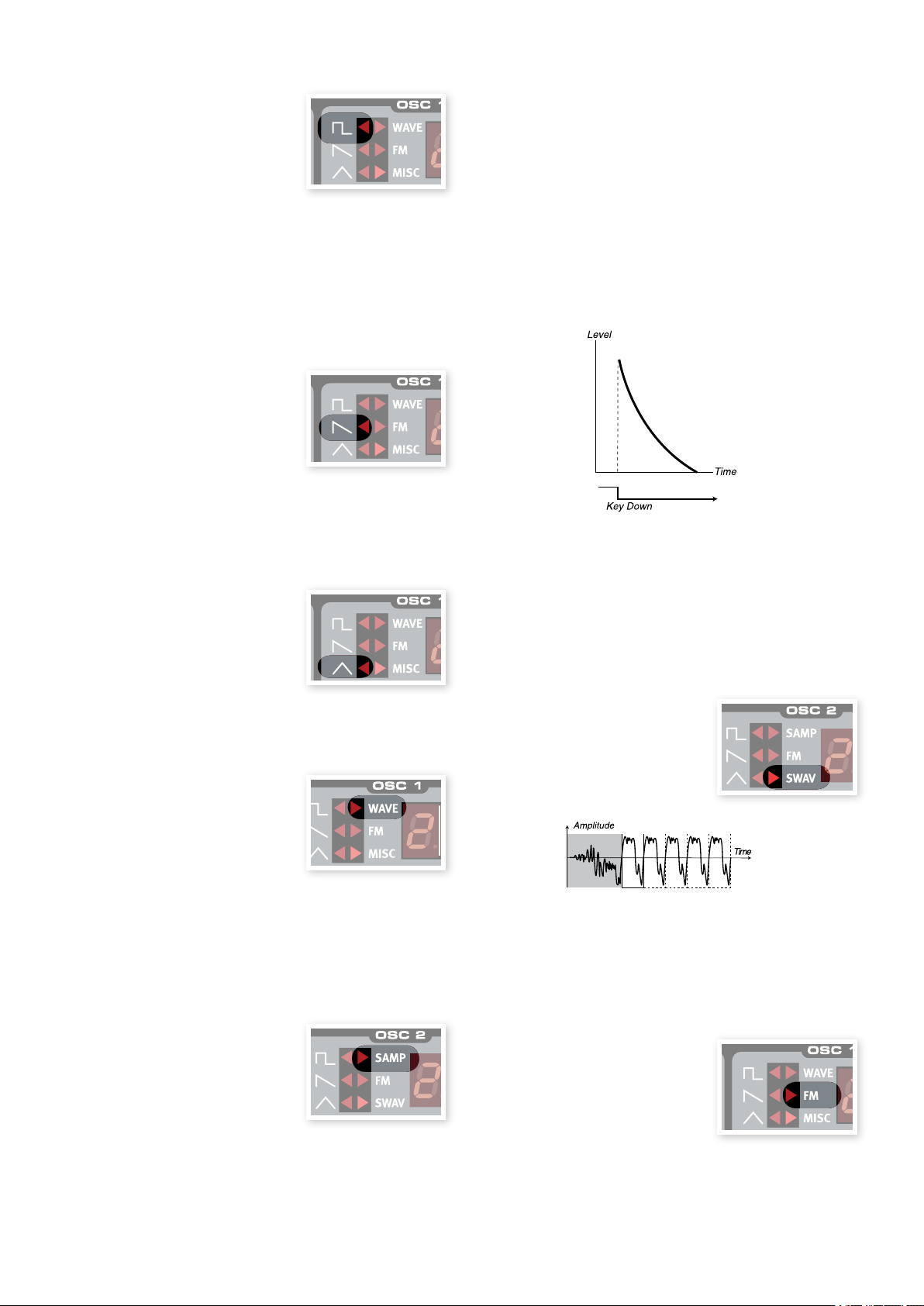
6NordWavereFereNce | 21
Single cycle loop
Attack section
Pulse
The Pulse waveform is available in OSC1
and OSC2 and has a hollow character
with only odd numbered harmonics.
The character can drastically change as
the width of the pulse is altered with the
Shape parameter. The narrower the pulse width, the more harmonics
will be present.
If you modulate the Shape value using an LFO, you can get very
nice “synthesized strings”.
If • Oscillator Sync is activated, the Shape knob is used for control-
ling the pitch of the Sync Oscillator. The pulse width is then locked at
33%.
Sawtooth
The Sawtooth waveform is available in
OSC1 and OSC2 and produces a very
rich sound that contains both even and
odd numbered harmonics.
Use the • Shape parameter to phase shift
two super imposed sawtooth waves up to a maximum 180 degrees
shift, which creates a perceived one octave shift.
If • Oscillator Sync is activated, the Shape knob is used for control-
ling the pitch of the Sync Oscillator.
Triangle
The Triangle waveforms is available in
OSC1 and OSC2 and has only odd numbered and not very strong harmonics.
Use the • Shape parameter to emphasize
the available harmonics in the spectrum.
If • Oscillator Sync is activated, the Shape knob is used for control-
ling the pitch of the Sync Oscillator.
Wavetable
Wavetables (WAVE) are available in
OSC1. These are single cycle sampled
waveforms that provides rich and interesting timbres with various tonal characteristics.
Use the • LED-dial to select a Sample Instrument. The name of the
selected Sample Instrument is shown in the LCD.
A flashing E
Sample Instruments at all are available in the Flash memory.
A flashing number in the E LED display indicates that the Sample
Instrument location that the current Program tried to use, is not
available in the Flash memory.
There is a special OSC2 only, amplitude decay envelope available
when the oscillator 2 is in the Sample Instrument or the Sampled Wave
mode. Use the Shape2/dec knob to control the decay time of the
OSC2 amplitude envelope.
The image above illustrates the phase of the decay envelope.
By setting the Shape1/DEC knob to the maximum the Decay
parameter will have an infinite setting; the envelope will have no
effect on your sound.
When the • SKIP SMPL ATTACK (Shift + Waveform Selector
button) is activated, playback will start at an alternative start point,
skipping the attack part of the sound.
-- character in the LED display indicates that no
Sampled waves
Sampled waves (SWAV) are available in
Osc2 and are similar to wavetables, but
are made out of recordings of acoustic instruments and still have the attack section
of the sample present.
There are 62 wavetables.
Use the • LED-dial to select a wavetable. The name of the selected
wavetable is briefly shown in the LCD window.
The • Shape parameter has no function when wavetables are se-
lected.
Sample Instruments
Sample Instruments (SAMP) is available
to OSC2 and holds up to 99 Sample
Instruments containing samples that are
stored in the Flash memory area.
A large selection of high quality samples
are installed when the Nord Wave is shipped from the factory, and even
more can be downloaded free of charge from the Clavia web site.
The Nord Sample Editor is the application that you use to create and
to download Sample Instruments from a computer to the Nord Wave.
The Editor is described in detail, in the Nord Sample Editor chapter in
this manual.
The image above shows the structure of a sampled wave.
Use the • LED-dial to select a sampled wave.
The • Shape parameter controls the decay time of the OSC2 ampli-
tude envelope, when this waveform is selected.
FM-Synthesis
FM-Synthesis (FM) is available in OSC1
and OSC2. This is a method where the
frequency of one Oscillator (referred to as
the Carrier) is being modulated by itself
using feedback or, by the frequency of
additional Oscillators (the Modulators).
Page 22

22 | NordWaveUserMaNUalv2.x
Shape2
(FM Amount)
Shape1
(FM Amount)
Carrier
Carrier
OSC MIX
OSC MOD
Modulator Modulator
The image above shows a 2 Operator FM-Synthesis setup, and the
resulting waveform using a fairly high FM amount setting.
The resulting waveform is far more rich in harmonics than the original
Sine waveform, and drastic changes in tonal character are provided by
altering the amount of modulation.
There are several FM algorithms available; set-ups with various number
of oscillators, feedback and frequency ratio settings between the oscillators.
Use the • LED-dial to select FM-algorithm.
The • Shape parameter is used for setting the amount of modulation
and/or feedback from none to maximum.
FM Algorithms
LED LCD Description (FB = feedback)
1-OP (+FB)
CR
2-OP 1:1
1
2-OP 2:1
2
2-OP 3:1
3
2-OP 4:1
4
2-OP 5:1
5
2-OP 6:1
6
2-OP 7:1
7
2-OP 8:1
8
2-OP 9:1
9
2-OP 1:1 (+FB)
1.
2-OP 2:1 (+FB)
2.
2-OP 3:1 (+FB)
3.
2-OP 4:1 (+FB)
4.
2-OP 5:1 (+FB)
5.
2-OP 6:1 (+FB)
6.
2-OP 7:1 (+FB)
7.
2-OP 8:1 (+FB)
8.
2-OP 9:1 (+FB)
9.
2-OP 9:1 (+FB)
9.
3-OP 1:1:1
11
3-OP 2:1:1
21
3-OP 3:1:1
31
3-OP 5:1:1
51
3-OP 9:1:1
91
3-OP 2:2:1
22
3-OP 4:2:1
42
3-OP 8:2:1
82
3-OP 1:1:1(+FB)
1.1
3-OP 1:2:1(+FB)
1.2
3-OP 1:3:1(+FB)
1.3
3-OP 1:5:1(+FB)
1.5
3-OP 1:9:1(+FB)
1.9
3-OP 1:1:2(+FB)
1.f
3-OP 2:1:1(+FB)
2.F
3-OP 3:1:2(+FB)
3.F
3-OP 5:1:2(+FB)
5.F
3-OP 9:1:2(+FB)
9.F
Carrier only, with feedback
Carrier + Modulator, same frequency
Carrier + Modulator, frequency ratio 2:1
Carrier + Modulator, frequency ratio 3:1
Carrier + Modulator, frequency ratio 4:1
Carrier + Modulator, frequency ratio 5:1
Carrier + Modulator, frequency ratio 6:1
Carrier + Modulator, frequency ratio 7:1
Carrier + Modulator, frequency ratio 8:1
Carrier + Modulator, frequency ratio 9:1
Carrier + Mod + FB, same frequency
Carrier + Mod + FB, frequency ratio 2:1
Carrier + Mod + FB, frequency ratio 3:1
Carrier + Mod + FB, frequency ratio 4:1
Carrier + Modulator, frequency ratio 5:1
Carrier + Mod + FB, frequency ratio 6:1
Carrier + Mod + FB, frequency ratio 7:1
Carrier + Mod + FB, frequency ratio 8:1
Carrier + Mod + FB, frequency ratio 9:1
Carrier + Mod + FB, frequency ratio 9:1
Carrier + Mod + FB, same frequencies
Carrier + Modulators, frequency ratios
2:1:1
Carrier + Modulators, frequency ratios
3:1:1
Carrier + Modulators, frequency ratios
5:1:1
Carrier + Modulators, frequency ratios
9:1:1
Carrier + Modulators, frequency ratios
2:2:1
Carrier + Modulators, frequency ratios
4:2:1
Carrier + Modulators, frequency ratios
8:2:1
Carrier + Mod + FB, same frequencies
Carrier + Mod + FB, freq. ratios 1:2:1
Carrier + Mod + FB, freq. ratios 1:3:1
Carrier + Mod + FB, freq. ratios 1:5:1
Carrier + Mod + FB, freq. ratios 1:9:1
Carrier + Mod + FB, freq. ratios 1:1:2
Carrier + Mod + FB, freq. ratios 2:1:1
Carrier + Mod + FB, freq. ratios 3:1:2
Carrier + Mod + FB, freq. ratios 5:1:2
Carrier + Mod + FB, freq. ratios 9:1:2
By combining OSC1 and OSC2, up to 6 operators are available, using
Oscillator Modulation (OSC MOD).
Oscillator Modulation is described on page • 24.
Page 23

6NordWavereFereNce | 23
Shape
(Feedback)
Shape
(FM Amount)
Shape2
(FM Amount)
Shape1
(FM Amount)
Shape
(Feedback)
Carrier
Carrier
Carrier
Carrier
Modulator
OSC MIX
OSC MOD
Modulator Modulator
9:1
Operators
A set-up with 2 oscillators (one Carrier and one Modulator) is called a 2
operator FM-Synthesis, indicated as
3 oscillators (one Carrier that is being modulated by one Modulator/
Carrier that also is being modulated by another Modulator) is called a 3
operator FM-Synthesis, indicated as
Note that a single Wave oscillator ( OSC1 or OSC2) in these
scenarios actually contains two (or three) oscillators.
FM-algorithms using only 1 operator (Carrier only) are also available,
1-OP
indicated as
Feedback
The first Operator in the chain can be given feedback to modulate
itself, creating more complex harmonics.
The • Shape parameter is used to control both the feedback and FM
amount simultaneously.
in the LCD, and CR in the LED window.
2-OP
in the LCD. A set-up with
3-OP
in the LCD.
Frequency Ratios are indicated by showing e.g. •
and simplified 9 in the LED display.
Sine
The Sine waveform is not available as a Waveform Type, but can be
generated by setting the Waveform Selector to FM and setting the
Shape parameter to zero.
Misc
The Misc category is available in OSC1
and contains a couple of special noise
algorithms and additional waveforms.
Noise - n1, n2 and n3
When any of the noise algorithms are selected, the oscillator produces
noise rather than a pitched waveform.
n1 - The color (aka frequency content) of this noise can be changed
with a 12 dB/octave lowpass filter which is controlled by the SHAPE1
knob. The further you turn the SHAPE1 knob clockwise, the brighter
the noise. At the maximum setting, the frequency content is very close
to that of white noise (where all frequencies are represented with equal
energy).
in the LCD,
An FM algorithm using Feedback is indicated with
and a dot (.) in the LED window.
Frequency ratio
By giving the Modulator a different frequency in relationship to the Carrier, you will get different harmonic characteristics.
(+FB)
in the LCD,
n2 - This is a narrow band of noise, which will give it a pitched char-
acter. Use the SHAPE1 knob to go from a wide band of noise to a
fluctuating sine wave.
n3 - This produces a noisy signal with a bright metallic timbre. The tim-
bre is created by a dense cloud of short pulses with carefully detuned
frequency relations, creating clusters of high pitched partials in its audio
spectrum a narrow band of noise, which will give it a pitched character.
The SHAPE1 knob acts like a highpass filter. When turned to the right
it will pull the timbre away into the highest parts of the audio range.
SO - This is a shapeable sine wave with addition of odd numbered
harmonics. At the minimum Shape setting, the signal is a perfect sine
wave and at the maximum setting a lot of odd numbered harmonics
have been added.
SA - This is a shapeable sine wave with addition of odd and even
numbered harmonics. At the minimum Shape setting, the signal is a
perfect sine wave and at the maximum setting a lot of harmonics have
been added, giving it a sawtooth character.
SS - This is a synchable sine wave. Use the SHAPE1 knob to change
the pitch of the sync oscillator.
PF - This is a “fixed” pulse waveform where the pulse width is adjusted
in absolute time values (with the Shape knob), i.e. the pulse width is
constant over the keyboard. This results in a spectrum with fixed formants, similar to the character of many acoustic instruments.
The Image above shows the Modulator having a frequency ratio relation of 9:1 to the frequency of the Carrier, and the resulting waveform
using a fairly high FM amount setting.
Shape parameter (Shape1 & Shape2/dec)
The Shape parameter is used for altering the waveform generated by
the oscillator. The exact functionality varies depending on what type of
waveform is generated. This is described for each different waveform
on the previous pages.
Range: 0.0 to 10.0
Page 24

24 | NordWaveUserMaNUalv2.x
Low-pitched note
High-pitched note
Low-pitched note
High-pitched note
Low-pitched note
High-pitched note
Semi Tones knob
The Semi Tones knob is used to adjust the
coarse tuning of oscillator 2, relative to oscillator 1. This is done in steps of semi tones,
ranging from -24 (-2 octaves) to +24 (+2
octaves) semi tones.
Range: -24 to +24
Fine tune knob
The Fine tune knob is used for fine tuning the pitch of Oscillator 2 .
Range: -50 to +50 semitones
If you have an equal OSC MIX setting, and a Semi Tones set-
ting of 0; slightly rasing or lowering the fine tune value will produce
a “richer” sound.
The red LED will light up when the pitch relationship between the
two oscillators is not in even octaves. If oscillator 2 is detuned to
oscillator 1 the LED will have an inverted state. It will be lit all the
time and momentarily go dark when an even octave is selected
with the Semi Tones knob.
Oscillator Modulation (Osc Mod)
Oscillator Modulation is about having the waveform produced by oscillator 2 modulating oscillator 1. Oscillator 1 will then produce a richer
waveform with more harmonics and these will increase as you apply
more modulation.
There are two types of Oscillator Modulation available: Frequency
Modulation and Phase Modulation.
By changing the frequency of oscillator 2 when the Oscillator
Modulation is active, you change the harmonic content of oscillator 1 - not its frequency.
The image above illustrates the harmonic content for a low-pitched
note and a high-pitched note using frequency modulation.
Some notes can sound more or less out-of pitch using high E
amounts of frequency modulation; this behavior is considered
normal.
Phase Modulation (PM)
Phase modulation generates the same relative harmonic content
regardless of in what note range you play, and is perceived as more
fluent, similar to using keyboard tracking with the filter.
The image above illustrates the harmonic content for a low-pitched
note and a high-pitched note using phase modulation.
Amount knob
The Amount knob controls the amount of modulation.
Range: 0.0 to 10.0
The waveform produced by OSC2 can be heard if you wish by using
the OSC Mix amount knob.
Frequency Modulation (FM)
Frequency modulation generates a wider spectrum and the resulting
sound is normally perceived as rawer and brighter. The harmonic content changes drastically depending on in what note range you play.
Type button
Press the type button repeatedly to activate and select the type of
modulation.
Settings: Off, frequency modulation (FM) or phase modulation
(PM).
Oscillator mix (Osc Mix)
Mix knob
The Oscillator Mix parameter is used for
setting the balance in amplitude between
oscillator 1 and oscillator 2.
With a setting of either OSC1 or OSC2,
only the corresponding oscillator will be heard.
Range: 1:100% to 2:100%
Page 25

6NordWavereFereNce | 25
Oscillator Sync (Sync)
When oscillator 1 is set to produce either pulse, triangle or sawtooth
waveforms, oscillator sync is available by activating the Sync function
(Shift + Waveform Selector button).
When the Sync function is activated an additional sync oscillator is
available. Each cycle of the waveform produced by the additional oscillator will restart the waveform cycle in the main oscillator.
Only the output of the main oscillator is heard, but since its waveform is
constantly restarted, it produces a richer harmonic content.
By altering the frequency of the additional oscillator, a different harmonic content is produced.
Use the • Shape knob to change the frequency of the additional oscil-
lator.
The illustration shows what happens when a sawtooth waveform is
synchronized to a sine waveform. The sawtooth restarts its cycle every
time the sine passes “zero”.
The image above illustrates the harmonic content of the non-synchronized sawtooth waveform compared to the synchronized sawtooth in
the previous example.
Amplier Envelope (AMP ENV)
The Amplifier Envelope is used to control how the amplitude of the
sound changes over time. By modulating the amplifier with an envelope, the sound can be given its basic “shape”. In fact, the “volume
shape” is one of the most important factors to how we identify the
sound. By setting up a proper amplifier envelope you can make a
sound “soft”, “hard”, “plucked” “static” etc.
•When a key is pressed, the envelope starts at the zero level, and
gradually reaches the maximum level during the time set by the
Attack Time (Attack knob).
When it has reached the maximum level the envelope will gradually •
fade to the Sustain Level (Sustain knob), during the time set by the
Decay Time (Decay knob).
When the key is released, the sound will instantly start to fade to zero •
during the time set by the Release Time (Release knob). The release
phase of the envelope will begin as soon as a key is released.
Page 26

26 | NordWaveUserMaNUalv2.x
The attack phase is the time it takes for the sound to go from zero to
full amplitude after a key has been pressed.
The release phase may start anywhere during the envelopes phases, it
will begin as son as a key is released.
A very short release time could produce a click in the end of the
sound. This is a normal physical phenomenon. To eliminate a click,
just increase the release time slightly.
Attack knob
The Attack knob sets the time interval for the Attack phase of the
envelope. This is time it will take for the sound to go from zero to the
full amplitude after a key has been pressed.
Range: 0.5 ms to 45 s
A very short attack time could produce a click in the beginning of
the sound. To eliminate this, just increase the attack time slightly.
When the attack phase is finished (and you haven’t released the
key), the decay phase takes over. During the decay phase, the sound
decreases in level, and continues to do so until it reaches the Sustain
level. With a decay setting of zero the Sustain Level will be reached
instantly after the attack phase of the envelope is completed.
With the Sustain Level set to the maximum, operating the Decay
knob will have no effect.
Decay knob
The Decay knob sets the time interval for the Decay phase of the
envelope. When the Attack phase is finished (and you haven’t released
the key), the Decay takes over. During the Decay phase, the amplitude
of the sound decreases, and continues to do so until it reaches the
Sustain level.
Range: 0.5 ms to 45 s
Sustain knob
Use the Sustain knob to set the level of the Sustain phase of the Envelope. This is the level the sound will reach after the envelope phase
has been completed. Once this has happened, the sound will stay at
this level until the key is released. With a setting of zero the amplitude
will reach zero after the Decay part of the envelope.
Range: 0.0 to 10.0
Release knob
Use the Release knob to set the time interval for the Release phase
of the envelope. This is how long it should take for the sound to decay
to silence after you have released the key. With a setting of zero the
envelope will instantly reach zero when the keys are released.
Range: 3.0 ms to 45 s
The sustain is the level the sound will reach after the decay phase is
finished. Once this has happened, the sound will stay steady at this
level until the key is released.
The Sustain parameter is used to set a level, while Attack, Decay and •
Release parameters are all used to set times.
The release phase is the time it will take for the sound to decay from
the envelopes current level to silence after you have released the key.
Page 27

6NordWavereFereNce | 27
Filter Frequency
Resonance = 10
Resonance = 0
Resonance = 3
Resonance = 7
Filter Frequency
Filter Frequency
Filter Frequency
Resonance = 10
Resonance = 0
Resonance = 3
Resonance = 7
Filter Frequency
Resonance = 10
Resonance = 0
Filter Frequency
Filter Frequency
Filter Frequency
Filter Frequency
Filter Frequency
Resonance = 10
Resonance = 0
Resonance = 3
Resonance = 7
Filter Frequency
Resonance = 10
Resonance = 0
Filter Frequency
Filter Frequency
Resonance = 10
Resonance = 0
Filter Frequency
Filter Frequency
Filter Frequency
Filter Frequency
Filter Frequency
Filter Frequency
Resonance = 10
Resonance = 0
Resonance = 3
Resonance = 7
Filter Frequency
Resonance = 10
Resonance = 0
Filter Frequency
Filter Frequency
Resonance = 10
Resonance = 0
Filter Frequency
Filter Frequency
Filter Frequency
Filter Frequency
Filter Frequency
Filter Frequency
Filter Frequency
Filter Frequency
Filter Frequency
Resonance = 10
Resonance = 0
Resonance = 3
Resonance = 7
Filter Frequency
Resonance = 10
Resonance = 0
Filter Frequency
Filter Frequency
Resonance = 10
Resonance = 0
Filter Frequency
Filter Frequency
Filter Frequency
Filter Frequency
Filter Frequency
Filter Frequency
Filter Frequency
Filter Resonance
Filter Frequency
Filter Frequency
Filter Vocal
Band Pass
Filter
A bandpass filter lets frequencies at the Filter Frequency setting to pass, while frequencies above and below the cutoff
will be attenuated.
The Filter Resonance sets the width of the frequency range that will •
pass through the band pass filter.
The Filter is one of the most important components to create the overall timbre of the sound. The harmonic content that the oscillators produce can be shaped with the filter and the filter itself can be modulated
with various functions. The Nord Wave features a selection of classical
synthesizer filters as well as some multi mode filters.
The Filters share the filter parameters: Filter Frequency controls the
cutoff frequency, the Resonance controls the filter resonance and the
Slope that sets how “steep” the filter slope will be when it is introduced
in the audio signal at the cutoff frequency.
The Slope button has an alternate function for the Comb, Multi
and Vocal filter.
Type button
Press repeatedly on the Type button to select the desired filter type.
The available filter types are:
Low Pass
Comb
The Comb filter uses a delay line with feedback
and a summing mixer to phase out frequencies of the original signal.
A gentle modulation of the Freq parameter will produce a classic
phaser type effect.
The • Freq knob is used for controlling the delay time; perceived as
the frequency center of the effect.
The • Res knob is used for controlling the level of the summing and
the feedback. A setting of zero will produce no summing or feedback
which results in the filter having no effect on the sound.
Frequencies above the Filter Frequency setting will
be attenuated, frequencies below will not be affected.
High Pass
Frequencies below the Filter Frequency setting will
be attenuated, frequencies above the cutoff will not be affected.
A resonance setting of 0 to 5 will gradually introduce notches in the
frequency spectra.
A resonance setting of 5 to 10 will gradually introduce resonant peaks
in the frequency spectra.
The • Slope button is used for setting the phase of the summation.
The Comb filter is best experienced with the keyboard tracking (• KB
Track) turned off.
Page 28

28 | NordWaveUserMaNUalv2.x
Filter Frequency
Filter Frequency
Filter Frequency
Filter Frequency
Filter Frequency
Filter Frequency
Filter Frequency
Filter Frequency
Filter Frequency
Filter Frequency
Filter Frequency
Filter Frequency
Filter Resonance
Envelope range
Time
Filter Frequency
Filter Frequency
Resonance = 10
Resonance = 0
Resonance = 3
Resonance = 7
Filter Frequency
Resonance = 10
Resonance = 0
Filter Frequency
Filter Frequency
Resonance = 10
Resonance = 0
Filter Frequency
Filter Frequency
Filter Frequency
Filter Frequency
Filter Vocal
Filter Frequency
Filter Frequency
Filter Frequency
Filter Frequency
Filter Frequency
Filter Frequency
Filter Frequency
Filter Frequency
Resonance = 10
Resonance = 0
Resonance = 3
Resonance = 7
Filter Frequency
Resonance = 10
Resonance = 0
Filter Frequency
Filter Frequency
Resonance = 10
Resonance = 0
Filter Frequency
Filter Frequency
Filter Frequency
Multi
The Multi filter applies three resonant peaks with
controllable center frequencies.
The • Freq knob is used for controlling the center frequency of the
peaks.
The • Res knob is used for controlling the resonance . A setting of
zero will produce no feedback which means the Multi filter will have
no effect to the sound.
The • Slope button is used for setting the character of the filter.
Vocal
The Multi filter is best perceived with keyboard tracking ( KB
Track) turned off.
Filter Resonance (Res knob)
Filter Resonance is used to emphasize frequencies around the Filter
Frequency, making the sound thinner. Further raising the Filter Resonance will make the sound resonant to a point where the filter adds a
ringing quality to the sound. Exactly where in the frequency spectrum
this “ringing” occurs, depends on the setting of the Filter Frequency.
Range: 0.0 - 10.0
The functionality of the Res knob varies depending on the se-
lected filter type. Please refer to the section on Filter Types on the
previous pages for more information.
Keyboard Tracking (KB Track button)
Keyboard Tracking is used for adjusting the Filter Frequency cut-off
point depending on where in the keyboard range you play.
The Vocal filter uses two resonant peaks to give
the sound an adjustable vowel character.
The • Freq knob is used for controlling the Filter Frequency.
The • Res knob is used for controlling the distance between the filter
peaks.
The • Slope button is used for controlling the filter resonance.
The Vocal filter is best perceived with keyboard tracking ( KB
Track) turned off.
Filter Frequency (Freq knob)
The Filter Frequency is used for setting the cutoff frequency point where in the frequency range the filter begins to process frequencies.
Range: 14 Hz - 21 kHz
This is related to basic acoustics; if you raise the pitch of a waveform,
the harmonics will also increase in frequency. If the cutoff frequency is
constant, the sound will be perceived as getting “muddier” the higher
up the keyboard you play.
With • KB Track disabled, the Filter Frequency cutoff is constant
regardless of where on the keyboard you play.
With • KB Track enabled, the Filter Frequency cutoff will be higher for
higher notes, and lower for lower notes. The point of reference is the
key of C2.
With • KB Track at the maximum setting of 1, the cutoff frequency
will track the keyboard in a 1:1 relationship.
With • KB Track at the 1/3 setting, the cutoff frequency will track the
keyboard in a 1:3 relationship.
With • KB Track at the 2/3 setting, the cutoff frequency will track the
keyboard in a 2:3 relationship.
This function is adjusted in a frequency/octave relationship. A set-
ting of 1 means that the cutoff frequency is moved one octave for
every octave you play from the C2 key.
The Image above illustrates three different Filter Frequency settings
using a low pass filter.
For the Multi Mode filters, the function of Freq knob varies. Please
refer to the section on Filter Types on the previous pages for more
information.
Filter Slope (Slope button)
The slope of a filter determines how steep the frequency attenuation
curve is, when the filter is introduced at the cutoff frequency.
Page 29

6NordWavereFereNce | 29
Filter Frequency
Resonance = 10
Resonance = 0
Resonance = 3
Resonance = 7
Filter Frequency
Filter Frequency
Filter Frequency
Filter Frequency
•When a key is pressed, the envelope starts at the zero level, and
The image above illustrates the difference between the two slopes using a Low Pass filter.
The • Slope button toggles the Filter Slope between 24db per octave
(4-pole) or 12dB per octave (2-pole).
The functionality of the Slope button varies in different filter types
Please refer to the section on Filter Types on the previous pages
for more information.
gradually reaches the maximum level during the time set by the Attack Time (Attack knob).
When it has reached the maximum level the envelope will gradually •
fade to the Sustain Level (Sustain knob), during the time set by the
Decay Time (Decay knob).
When the key is released, the modulation will instantly start to fade to •
zero during the time set by the Release Time (Release knob). The
release phase of the envelope will begin as soon as a key is released.
Velocity button
The Velocity button sets the filter in Velocity mode. In this mode the
Filter ENV Amount will change depending on the note velocity data;
the harder you play, the more effect will the Filter Envelope have on the
Filter Frequency.
The • Env Amt knob is used for setting the intensity of the change.
The image above illustrates how the Env Amt knob enables note
velocity to change the Filter Frequency.
Filter Envelope
The attack phase is the time it takes for the modulation to go from zero
to the maximum modulation after a key has been pressed.
A very short attack time could produce a click in the beginning of
the sound. This is a normal physical phenomenon. To eliminate
this, just increase the attack time slightly.
The Filter Envelope is used to modulate or control the Filter Frequency
cutoff in the time frame from when a key is pressed down, to after it
has been released again.
By modulating the filter with an envelope, the sound can be given its
harmonic “shape”. By setting up a proper filter envelope you can make
a sound “soft”, “hard”, “plucked” “static” etc.
When the attack phase is finished (and you haven’t released the key),
the decay phase takes over. During the decay phase, the modulation
decreases, and continues to do so until it reaches the Sustain level.
With a decay setting of zero the Sustain Level will be reached instantly
after the attack phase of the envelope is completed.
With the Sustain Level set to the maximum, operating the Decay
knob will have no effect.
Page 30

30 | NordWaveUserMaNUalv2.x
The sustain is the modulation level the envelope will reach after the
decay phase is finished. Once this has happened, the modulation will
stay steady at this level until the key is released.
The Sustain parameter is used to set a level, while Attack, Decay and •
Release parameters are all used to set times.
Sustain knob
Use the Sustain knob to set the level of the Sustain phase of the Filter
Envelope. This is the level the modulation will reach after the Decay
phase has been completed. Once this has happened, the modulation
will stay at this level until the key is released. With a setting of zero the
modulation will reach zero after the Decay part of the envelope.
Range: 0.0 to 10.0
Release knob
Use the Release knob to set the time interval for the Release phase of
the Filter Envelope. This is how long it should take for the modulation
to decay to zero after you have released the key. With a setting of zero
the envelope will instantly reach zero when the keys are released.
Range: 3.0 ms to 45 s
Output
The release phase is the time it will take for the envelope to decay
from the envelope’s current level to zero level after you have released
the key. The release phase may start anywhere during the envelopes
phases, it will begin as son as a key is released.
A very short release time could produce a click in the end of the
sound. This is a normal physical phenomenon. To eliminate such a
click, just increase the release time slightly.
Envelope Amount (ENV AMT knob)
Use the ENV AMT knob to determine how much the Filter Envelope
should affect the cutoff frequency.
Range: 0.0 to 10.0
Attack knob
The Attack knob sets the time interval for the Attack phase of the
Filter Envelope. This is time it will take for the modulation to go from
zero to the level set by the Envelope Amount knob after a key has been
pressed.
Range: 0.5 ms to 45 s
Decay knob
The Decay knob sets the time interval for the Decay phase of the Filter
Envelope. When the Attack phase is finished (and you haven’t released
the key), the Decay takes over. During the Decay phase, the modulation decreases, and continues to do so until it reaches the Sustain
level.
Range: 0.5 ms to 45 s
Level knob
The Level knob is used for setting the amplitude (the volume) of the Program. The setting
of this parameter is stored when the Program
is stored.
Morph this parameter with velocity of you need to make the ampli-
tude of a sound velocity sensitive.
Note that the E Master level at the upper left on the panel controls
the overall amplitude, where as the Output Level only controls the
amplitude of the active Slot.
Equalizer (EQ)
The 2-band equalizer with a shelving characteristic that can be used for boosting or cutting
frequencies in the sound.
Range: from -15dB to +15db
Treble knob
Applies a cut or boost on the treble frequencies
of the sound, above 4 kHz.
Bass knob
Applies a cut or boost in the bass frequencies of the sound, below 100 Hz.
The red LEDs will be lit when the knob’s position is set to anything
other than 0.
Page 31

6NordWavereFereNce | 31
Tap Tempo button
Chorus
Chorus is an effect that simulates what happens if you have more than one instrument
playing the same notes. This effect can make
the sound “broader” or warmer.
The Tap Tempo button allows you to set a tempo setting of the delay
effect by tapping it. By repeatedly tapping this button, the tempo is
set to match the interval as you hit the button. The more times you tap,
the more accurate will this interpretation be, but two taps may also be
sufficient.
The Chorus effect is very subtle in mono operation.
Chorus button
Press repeatedly on the Chorus button to activate the effect and to
select one of the 3 intensity settings.
Range: Off (no LED is lit, 1, 2, and 3 (both LEDs are lit)
The Chorus and EQ effects are individual to both the Slots in a
Program.
Program Effects
The Program Effects are 3 effect units that are common to both the
Slots in a Program.
Delay
The delay can add an echo effect to the sound.
The Delay can operate in mono or in stereo,
with the delayed sound appearing in an alternat-
ing pattern in the left and right audio channel.
Tempo LED
The Tempo LED indicates the time between
the repeats in the delay effect.
On/Off button
Turns the delay effect on or off.
Tube Amp
The Tube Amp effect adds a tube-style over-
drive to the sound.
Drive knob
The Drive knob controls the amount of overdrive.
Range: 0.0 to 10.0
On/Off button
Turns the Tube Amp effect on or off.
Reverb
The Reverb effects simulates natural sound
reflections in various acoustic environments.
Dry/Wet knob
The Dry/Wet knob controls the balance in
amplitude between the unprocessed (dry) and
processed (wet) signal.
Tempo knob
The Tempo knob sets the time interval between
the repeats.
Range: 2.26 s to 64 ms
Feedback button
The Feedback button allows you to select the amount of repeats.
There are 4 settings to chose from, ranging from one repeat (no active
LEDs), to several (1 & 2 LED are lit). Press the feedback button repeatedly to select the desired feedback level.
Stereo button
The Stereo button (Shift + Feedback button) activates the delay in
stereo operation. The repeats will appear in the left and then the right
audio channel, in an alternating pattern.
Amount knob
The Amount knob controls the amount of the delay effect in the audio
signal.
Range: 0.0 to 10.0
Reverb button
The Reverb button selects the type of reverb effect:
Setting Description
Room Small reverberation with room ambiance and a fast
decay.
Stage Soft Medium reverberation with stage ambiance, me-
dium decay and a mellow character.
Stage Medium reverberation with stage ambiance, me-
dium decay and a bright character
Hall Soft Full reverberation with a hall ambiance, slow decay
and a mellow character.
Hall Full reverberation with a hall ambiance, slow decay
and a bright character.
On/Off button
Turns the Reverb effect on or off.
Page 32

32 | NordWaveUserMaNUalosv2.x
Nord Sound Manager
7
The Nord Sound Manager is the application that allows you to organize the various memory areas, the partitions in the Nord Wave. It is also used to
download samples or programs to the Nord Wave or to upload any of these items - called sounds - from the Nord Wave memory to the computer
hard drive. The Nord Sound Manager provides access to various methods to download the sounds to the Wave and a function to backup and
restore the entire Nord Wave memory.
System requirements
The Nord Sound Manager is compatible with computers running Mac OSX 10.4 or later, Windows XP and Windows Vista. If you run the Nord Manager on a Windows computer, you also need a Clavia USB Driver of version 2.14 or later installed. The Nord Wave OS has to be 2.0 or later.
Nord Wave OS Updates, USB drivers and instructions on how to install these are available at the www.nordkeyboards.com website and on the M
DVD that accompanies this unit.
Overview
You can work with the contents of the Sample partition and the Program partition. These are accessed from the tabs, conveniently labeled,
Samp Lib and Programs.
If no Nord Wave is connected to the computer, pages, icons and
memory locations will be grayed out.
The actions that take place in the Nord Sound Manager will affect E
the memories in the Nord Wave. The Manager is on-line with a
connected Wave at all times; any changes that you perform in the
Manager will immediately be executed in the Nord Wave. If you
e.g. delete a sample or a Program from the list in the Nord Sound
Manager, that same sample or Program will also be deleted from
the Nord Wave Flash memory.
The Toolbar
The Toolbar gives you direct access to some of the more frequently
used functions in the Nord Sound Manager. Clicking on an icon will
activate one of these functions, and a dialogue will often appear asking
for confirmation or further instructions from you.
The Tabs
Select the partition that you wish to work in with the Tabs. The Samp
Lib tab is the sample partition and the Program tab allows you to organize the programs. The individual samples or programs will be referred
to as “sounds” in this manual and in the application itself.
Press Ctrl+Tab on the computer keyboard to cycle between the
tabs.
The lists can be ordered according to location, name, size, version and
date, in ascending and descending order. Just click on a headline to
select a preferred view.
Partition Memory Indicator
The memory indicator at the bottom of the window indicates how much
memory is being used in the selected partition. The red area shows the
used memory, green indicates space that is available for new sounds.
Right-Clicking
If you right-click on a sound, a context menu will provide the following
options:
Page 33

7NordsoUNdMaNaGer | 33
Select in Instrument
This will select the chosen sound in the Manager list, to be instantly
accessible on the Nord Wave.
The Quick Tour
Let’s get acquainted with some of the functions in the Nord Sound
Manager.
Upload
This will upload the selected sound from the Nord Wave to the computer hard drive to a folder of your choice.
Download
This is only available if you right-click on
an empty location that does not contain a
sound. This allows you to choose a file on
the hard drive, to be downloaded to the
location in the Nord Wave.
Transfer samples to the Wave
When the Nord Wave leaves the factory, the sample partition is filled
with sounds. In order to be able to download additional samples, you
may have to delete some of the factory samples. If you ever want to
reload any deleted samples, they are available on the DVD that was included with the Nord Wave, or available as a download from the www.
nordkeyboards.com web site, in the Libraries area.
Deleting a sample
Rename
This allows you to rename, and assign a category to a Program. Characters supported are: a-z, A-Z, 0-9 and a hyphen (-) and the name can
contain up to 16 characters. Any other characters will not be displayed
in the File Manager lists.
Samples cannot be renamed, this option will not be available if M
you right-click on any of these.
Delete
This will delete the selected sound(s) from the Nord Wave memory.
File Formats
The Nord Sound Manager creates and uses files with the following
extensions:
Connect the Nord Wave to the computer and launch the Nord 1
Sound Manager.
2
The Sample tab will open and the current content of the sample
partition in the Wave will be displayed.
Select a sample to delete and press the Delete icon in the toolbar.3
You can also right-click on the sound and choose the Delete option or
use the backspace or delete keys on the computer keyboard.
4
You will be asked to confirm your intentions and then the sample
in the Wave will be deleted.
.nsmp - These are the sample files from the Nord Sample library.•
.nwp - These are the Program files. •
.nwb - This is the extension used for the Nord Wave backup files.•
.nwi - This is an older sample format that previous versions of the •
Nord Wave Manager created. They can still be used by the Nord
Wave (but not the Electro 3) and the Nord Sound Manager.
Just as any other computer file on your hard drive, these files may be
renamed, emailed, copied, moved, lost or even stored in a safe location if an evil computer crash suddenly decides to take your hard drive
for ride.
Download a new sample
Using drag and drop1 : Open the folder on the computer hard
drive where the new sample (in the .nsmp format) is located.
2
Make sure that the File Manager window and the folder are visible
on the screen.
Drag the new sample to the white area in the File Manager sample 3
list. When the destination location will turn gray, release the mouse
button.
4
The Clean Deleted Space process will start to prepare the memory and then the new sample will be downloaded to the Wave. If
there isn’t enough free space, a message will appear in the lower
left text area in the Nord Sound Manager.
If the Organize option is active in the View menu, you can drop
a sound on any free location in the bank. If this function is not
active, the new sound will be automatically placed at the first free
location in the bank. The various locations are selected using the
Type selector on the Nord Wave.
1 : Click on the Sound
Using the Toolbar or Menu command
Down icon in the toolbar. The same command is also available in
the File menu: Sound Download (Ctrl-D).
Page 34

34 | NordWaveUserMaNUalosv2.x
Browse to the folder on the hard drive where the desired sound is 2
located, select it and click Open. The sample will now be added
to its bank.
These methods can also be used with any sample or individual
programs that you wish to add.
Upload sounds from the Wave
Select the desired partition that holds the sounds that you wish to 1
store on the computer hard drive.
Select the bank and the sound. Shift-click will allow you to select 2
several consecutive sounds; Ctrl-click will allow you to select
nonconsecutive sounds. Here we have selected a few of the
samples:
3
Click on the Sound Up tool or right-click on the selected sound(s)
and select Upload. The dialogue will prompt you to browse to the
desired destination folder on the hard drive. The upload process
may take a few moments depending on the size of the sounds.
Upload a complete partition to the hard drive
Make sure that the desired partition (and bank) is focused in 1
the Nord Sound Manager. You will also have the opportunity to
change the source bank in an upcoming dialogue.
When you click on Download a dialogue appears to inform you M
that the content of the destination bank in the Nord Wave will be
replaced with that of the source file.
If you select All in the destination bank drop down, you can replace all
the sounds in a partition with those on a folder structure on the hard
drive. If Search Subfolders is active, you can browse to the top folder
of a structure as the parent of the source files.
Organize the program partition
By using drag and drop, you can organize the content of the Program
partition with its 128 programs.
Make sure that Organize is activated in the View menu.1
Select and drag a program from the destination location to the 2
desired location.
If you drop a sound on a free location, the sound will be moved from
the source location. If you drop on a location that is occupied, the two
sounds will trade places.
3
Select a program and press the Ctrl-key on the computer keyboard. If you now drag this selection, the Program will be copied
and pasted at the destination instead of just being moved.
2
Click on the Bank Up tool, or select the File/Bank Upload menu
command (Ctrl-Shift-U). Verify that the source bank is correct and
browse to the desired destination folder on the computer hard
drive.
You can also select All at the bottom of the sample bank list drop
down. This will upload the entire content of the partition to the computer hard drive.
If the Create Subfolders option is checked, a folder structure - partition/
bank/sounds - will automatically be created in the destination folder.
Download sounds to the Wave
Click on the Bank Down tool, or select the File/Bank Download 1
menu command (Ctrl-Shift-D).
Verify that the destination bank is correct and browse to the de-2
sired source folder on the computer hard drive.
Search Box
By entering one or several characters in the Search Box, you can 1
filter out the content that is presented in the lists.
This provides you with a quick way to find duplicate programs, all
programs made by the mysterious AD (Ake Danielsson) or all programs
with e.g. the phrase “string” in their names.
Auto Select
By clicking on the Auto Select icon in the toolbar, you toggle the Auto
Select function on or off.
When this is activated and you scroll through the Program or Sample
list using the computer keyboard arrow keys, the Program (or Sample)
will be automatically selected in the Nord Wave.
Double-clicking on a Program or Sample will also select it in the
Wave.
Page 35

7NordsoUNdMaNaGer | 35
Bank Up
Nord Sound Manager reference
Toolbar
Organize
When this option is active, the lists will show all the available locations
in the selected partition/bank and not only the occupied ones. This will
for instance make it easier to drag a file to a specific free location in the
middle of the list. If this is inactive, only the occupied locations will be
shown.
Dual View
When this option is checked, the window will be divided in two lists.
The two lists makes it easy to move programs from one location to
another. You can make the lists show separate banks with the dropdowns. Rearranging programs is simply a matter of drag and drop.
Drag a program from one bank/list to another bank/list in either direction.
This function will upload an entire bank of samples or programs to the
computer hard drive. The default source will be the currently active
bank, but you may choose another partition and bank if you wish.
Click on the Choose Folder button to select the destination on the hard
drive.
If the Create Subfolders option is checked, a folder structure will automatically be created in the destination folder.
If a folder with the same name as the source partition/bank M
already exists in the location on the hard drive, this folder’s entire
content will be replaced by the uploaded files from the Nord
Wave.
Bank Down
This function will download an entire bank of samples or programs
from the computer hard drive to the Nord Wave. The default destination
will be the currently active bank, but you may choose another partition
and bank if you wish. Click on the Choose Folder button to select the
source on the hard drive.
The destination bank in the Wave will be replaced by the content E
of the source folder.
Auto Select
With this function active, scrolling through the program list with the
computer keyboard arrow keys will automatically select the programs
in the Nord Wave.
Sound Up
Use this function to upload one or several sounds from the Nord Wave
to the computer hard drive.
Sound Down
Use this function to download one or several sounds from the computer hard drive to the next available location in the selected partition.
Rename
This allows you to rename, and assign a category to a Program. 16
characters can be used, and the supported characters are: a-z, AZ,
0-9 and the hyphen (-). Any other characters will not be displayed in
the Manager lists.
Samples cannot be renamed so this function is not available if you M
have selected any of these.
Delete
Allows you to delete one or several selected sounds. You will be asked
to confirm your intentions. You may also use the delete or backspace
key on the computer keyboard to perform this action.
Backup
This will make a backup of all the samples and programs and Menu
settings (System & MIDI menus) in the Nord Wave. The file that is created on the hard drive will have the extension .nwb. Backing up the
entire memory content in this manner will take some time, depending
on the sizes of the samples.
Backing up from the Nord Sound Manager is done in an incre-
mental manner. Unless you change the name or the location of
the back up file, only the samples and/or programs that have been
changed since the previous backup will be saved.
The Nord Sound Manager will suggest a location for the backup, the
first time this function is activated (in My Documents/Nord Sound
Manager files/). If you rather save the backup file elsewhere, use the
browser to pick another destination.
Restore
To restore a previously saved backup file to the Wave, select this option
and browse to a backup file on the hard drive (file extension .nwb) and
click Open.
The restore function will begin after you have clicked Open and E
confirmed your intentions in the dialogue. All the content of a
connected Nord Wave will then be irrevocably replaced by the
content of the backup file.
Any Program in the Nord Wave that used that particular sample M
that you deleted will probably not sound at all, since it will be
missing an important component.
The space that a deleted sample occupied is not immediately available
to other sounds, even though it is gone from the list and its location
is free. The Flash memory needs to be cleaned to free up the space
where the deleted sounds have been. When you add a new sample
the cleaning process will be initiated automatically. You also have the
option to manually start the cleaning process with the Clean Deleted
Space command from the File menu.
A flashing number in the Nord Wave Osc 2 LED display indicates M
that the sample that the current Program tried to use is not available in the Flash memory. Select another program or download
the missing sample to the Wave.
Page 36

36 | NordWaveUserMaNUalosv2.x
Menus
In the Nord Sound Manager, the usual Windows and Mac OSX keyboard commands can be used. The menus can be accessed by pressing the Alt key and the underlined letter in the menu bar.
Most of the commands can also be accessed by pressing the Ctrl (on
the Mac - Command) key together with the letter shown next to the
command name in the menus.
File
Sound Upload (Ctrl+U)
Use this function to upload one or
several sounds from the Nord Wave
memory to a folder on the computer
hard drive.
Clean Deleted Space
This function will clean up the space where any previously deleted
samples or programs have been. This is done in order to make this
deleted memory space available to new additions.
Cleaning is automatically done if you download a new sample or M
program to the Nord Wave, but this menu command makes it
possible to manually start the cleaning process.
Format
This is a radical function; it will format the entire partition that is in
focus. All the sounds in the partition will be deleted. You will be asked
to confirm your intentions.
Exit (Ctrl+Q)
Exits the Nord Sound Manager application.
Edit
Sound Download (Ctrl+D)
Use this function to download one or several sounds from the computer hard drive to the next available location in the selected partition.
Bank Upload (Ctrl+Shift+U)
This allows you to upload an entire bank or partition (samples or
programs) to a folder on the computer hard drive. Select the desired
source (partition and bank) and the destination folder.
If you select All, all the banks in the partition will be uploaded. The hierarchical folder structure of the chosen partition - partition/bank/sounds
- will be automatically created in the destination folder.
Bank Download (Ctrl+Shift+D)
Use this function to download an entire bank (or all banks) from the
hard drive to the Nord Wave.
Please note that you need to match the format of the source and the
destination, it is e.g. not possible to download a set of programs to any
of the sample banks.
The content of the source folder will replace the selected bank in M
the Nord Wave.
Backup (Ctrl+B)
This will make a backup of all the samples, programs and menu settings (System & MIDI menus) in the Nord Wave.
The file that is created on the hard drive will have the extension .nwb.
Backing up the entire memory content in this manner will take some
time, depending on the sizes of the samples.
Backing up from the Nord Sound Manager is done in an incre-
mental manner. Unless you change the name or the location of the
back up file, only the samples and/or programs/patches that have
been changed since the previous backup will be saved.
Restore (Ctrl+R)
To restore a previously saved backup file to the Wave, select this option
and browse to a backup file on the hard drive (file extension .nwb) and
click Open.
The restore function will begin after you have clicked Open and E
confirmed your intentions in the dialogue. All the content of a
connected Nord Wave will then be irrevocably replaced by the
content of the backup file.
Rename (Ctrl+N)
This allows you to rename, and assign
a category to a Program. 16 characters can be used, the supported
characters are: a-z, A-Z, 0-9 and the
hyphen (-). Any other characters will not be displayed in the Sound
Manager lists.
Samples cannot be renamed so this function is not available if you M
have selected these.
Delete
Allows you to delete a selected item(s) from the Nord Wave memory.
You will be asked to confirm your intentions.
Select All (Ctrl+A)
Select all items in a bank/partition.
Invert Selection
This will deselect the original selection and then select all the other
items in the list.
View
Organize (Ctrl+O)
When this option is checked, the lists
will show all the available locations in
the selected partition/bank and not only
the occupied ones. This will for instance
make it easier to drag a file to a specific free location in the middle of
the list. If this is unchecked, only the occupied locations will be shown.
Dual View (Ctrl+L)
When this option is checked, the window will be divided in two lists.
The two lists makes it easy to move programs from one location to
another. You can make the lists show separate banks with the dropdowns. Rearranging programs is simply a matter of drag and drop.
Drag a program from one bank/list to another bank/list in either direction.
Press the Ctrl-key on the computer keyboard to copy a selection
to the destination during a drag and drop operation.
Auto Select (Ctrl+K)
When this function is active, programs will be automatically selected in
the Nord Wave when you browse through the Programs in the Manager list, with the computer keyboard arrow keys.
Page 37

7NordsoUNdMaNaGer | 37
Help
About
Brings up the About box with a information regarding the version of the Nord Sound Manager. You will also see a list of
compatible instruments and OS versions.
Tabs
Samp Lib - Program
Use the tabs to select the desired partition. Type Ctrl+Tab on the computer keyboard to cycle between the two tabs. The drop down menu
is used to select the desired bank within the Program partition. The
content of the partition will be presented in the list.
Search Box
Enter a phrase to quickly present any samples or programs that
contains the characters. Press Clear to clear the filtering and show all
entries again.
Footer Area
The footer area is located at the bottom of the Nord Sound Manager
window.
Partition Memory Indicator
This indicates the usage of the selected partition’s memory. The red
area shows the used memory and the green area indicates space that
is available for additional sounds.
Cancel Button
Use this function if you need to cancel a process that is in progress.
Certain functions like e.g. a restore process cannot be cancelled.
Progress Bars
The two progress bars indicate the progress of an ongoing process.
The upper bar shows the progression of the individual processes, and
the lower indicates the status of the entire task.
Loc - Location
The banks are organized in locations; the number of locations varies for
the different bank types.
Name
The name of the item.
Category
Shows the assigned category for the Programs.
Size
Shows the file size of the samples. This may be useful if you need to
know how much space e.g. a particular sample occupies in the sample
partition. This unit is not shown in the program list.
Ver – Version Number
This indicates the version number of the actual sample or program
format.
Message/Text Area
The left part of the text area will present any confirmations or error
messages from the Nord Sound Manager.
The right part will indicate of a Nord Wave is connected to the computer and in communication with the Nord Sound Manager. The OS
version of the connected Wave will also be displayed here.
Updates and samples
Please visit our website at http://www.nordkeyboards.com to download any updates of the Nord Sound Manager and sounds that have
been released for the Nord Wave. These items will be available as free
downloads in the Nord Wave download area.
Info
This area may contain error information about broken, corrupted or
rejected files, if e.g. something has happened with a particular sample
in the Wave.
Page 38

38 | NordWaveUserMaNUalosv2.x
Nord Sample Editor
8
What is the Nord Sample Editor?
The Nord Sample Editor is the application that allows you to edit, create and load collections of samples to and from the sample memory
area of a Sample Library compatible Nord instrument.
The Nord Sample Editor will assist you in your editing efforts; it contains
powerful tools for various actions that can be applied to a sample.
These tools will for instance help you in setting a start point of a
sample, creating a loop and other tasks that are essential in making the
samples ready for use in the Nord Wave. The Editor also has functions
for automatic mapping of samples across the keyboard and much
more.
Project, sample memory
All the parts that are needed to assemble a sample waveform in the
Nord Wave – references to audio files, samples, mappings, start-, stopand loop markers etc. - are organized in Projects.
All Project related settings is done on your computer, and you can
preview edits via the computer audio card. A Project links to the actual
audio files on the hard drive, if you e.g. delete or edit an audio file that
is included in a Project, that Project will be affected.
You can save Project files on the hard drive, just like any other computer file. When you are satisfied with a Project, you can generate a
Sample Instrument, which can be downloaded to the Flash memory in
the Nord Wave.
Non-destructive editing
Any editing that takes place in the Nord Sample Editor software is
completely non-destructive. The audio files on your hard disk will not
be altered in any way even though the Nord Sample Editor will e.g.
truncate samples before they are downloaded to the Nord instrument.
If you edit any audio file that is used by the Nord Sample Editor with
some other application, that edit will also affect that particular file in the
Nord Sample Editor.
System Requirements
Windows PC
The Nord Sample Editor requires a computer with Windows XP or
Vista. Additionally you need one free USB port plus a DVD ROM drive if
you want to install the software from the DVD.
Mac
The Nord Sample Editor requires a Mac with one USB-port, a DVD
ROM unit to install the software and OSX 10.4 or later.
Nord
You will also need a Sample Library compatible Nord instrument to be
able to download the samples. The Nord units that are compatible with
the Sample Editor and the Nord Sample Library are: Nord Wave with
OS v2.x and later and the Nord Electro 3 with OS 1.x or later.
WYDIWYH
What You Do Is What You Hear. Every function in the Nord Sample
Editor can be applied to a sample in real time. If the sample is playing
back through the computer audio card, you can e.g. listen to how the
loop changes if you move the loop markers or if you adjust the crossfade settings or the start point of the sample.
Working ofine
Project or sample editing does not require a connected Nord unit; you
can create and edit Projects using only the computer and then connect
to the unit at some other time in order to download the result of the
Project to the Nord Wave.
Sample, Zone
When an audio file is added to a Project, it can be used as the source
for one or several samples. A sample can be assigned to a range on
the keyboard; this range is called a Zone. The sample parameters that
determine the range of its zone is the Root Key and the Upper Key.
Sample Instrument
A set of samples with zone settings is a Sample Instrument; the maximum number of zones in a Sample Instrument is 91. The Sample Instrument can be selected in the Nord Wave oscillator 2 as a waveform
and by choosing the SampLib type and model in the Electro 3.
Getting Started
Let’s begin with a brief description of the terminology used in this chapter, followed by a typical workflow scenario to give you an overview of
the functions of the Nord Sample Editor.
Any kind of sample may be assigned to any zone, which means that
a Sample Instrument can consist of several different sounds, mapped
across the keyboard. You can e.g. create a drum type Sample Instrument with one sound for each key, or create multiple splits by assigning
different samples to different keyboard ranges – e.g. bass samples
in the lower register, followed by piano samples higher up on the
keyboard.
Page 39

8NordsaMPleedItor | 39
Sample editing, loop markers, crossfade
Setting a starting point for a sample to e.g. eliminate any unwanted audio at the beginning, is a one-click function in the Nord Sample Editor.
The Editor has some very powerful loop functions that make creating
perfect, seamless loops a breeze. The loop makes it possible to use
shorter samples that still can be played for a duration that is longer
than the sample itself. The loop functions also includes a crossfade
option that can be monitored in real time, with various options for the
length, crossfade curves etc.
The Quick Tour
Let us go through a few things we know you are curious about and get
acquainted with the Nord Sample Editor at the same time.
Generate, upload, download
When a Project is completed, you can generate a Sample Instrument
and automatically download the wave data to the Flash memory in the
Nord Wave. The real estate of the Flash memory has a fixed capacity
and to keep track on how much room you have left, there is an indicator in the Nord Sample Editor that will help you to manage the available
space.
Installation
Installation of the USB driver
Before the Nord Wave can communicate with a Windows PC, you
need to install a Clavia USB driver for the Windows operating system.
Mac users may skip this paragraph. To install the USB driver, follow
these instructions:
1
Insert the ‘Nord DVD’ installation DVD into the DVD-ROM drive or
get the driver from the Nord Wave download area at
www.nordkeyboards.com.
2
Connect the USB cable between the Nord Wave and the computer and power up the unit. The ‘Found New Hardware’ wizard
should appear, accompanied by its reassuring alert sound.
Let the wizard search the installation DVD for the USB driver and 3
install it, or point the wizard to the folder where the driver is.
Installation Windows PC
Insert the ‘Nord DVD’ into the DVD-ROM drive.1
Run the Install Nord Sample Editor v2.xx.exe and follow the 2
instructions in the setup program.
3
The Nord Sample Editor will be installed in the Program Files folder
on the hard disk.
Nord Sample Editor Audio File/Assign tab with an audio file,
with assigned samples
First Light
Make sure that the Nord Wave is powered up, and connected to 1
the computer, to a USB port.
2
Launch the Nord Sample Editor from the Program Files folder or
the Start Menu (PC) or from the Applications folder (Mac OSX).
During the start-up procedure, the Editor will automatically try and
establish contact with the Nord Wave.
If a Nord Wave is not connected, you can still work on a Project with
sample editing, mapping and other functions. When the Editor finds a
Nord Wave, this will be indicated at the lower, right corner of the Editor
window and the Manager tab will open automatically. A list with all the
current Samples in the Flash memory will appear in the Nord Sample
Editor window.
During the installation you will have the option to select an alternative
location for the application.
4
Confirm every window in the installation procedure by clicking on
the Next button. The installation may be aborted at any time by
clicking on Cancel. When the installation is complete, click the
Close button to return to the Windows desktop.
Installation Mac OSX
Insert the ‘Nord DVD’ into the DVD-ROM drive.1
Open the image file (.dmg) that is located in the Nord Sample Edi-2
tor folder on the DVD and drag the Nord Sample Editor v2.xx.app
to the Applications folder.
When new versions of the Nord Sample Editor are released, they
will be available as a free download at www.nordkeyboards.com.
In order for the Nord Sample Editor to be able to playback
samples, you need to select a driver for your audio card. This is
done in the Settings/Audio menu.
On a XP or Vista system, select an available Direct X driver. In M
order to be compatible with as many XP and Vista computer systems as possible, the Nord Sample Editor uses Direct X drivers.
Page 40

40 | NordWaveUserMaNUalosv2.x
Download Sample Instruments
You can find new Sample Instruments at the www.nordkeyboards.com
website. These can be downloaded from the website free of charge.
Here’s how to download a Sample Instrument from the computer hard
drive to the Nord unit:
1
Browse to www.nordkeyboards.com and go to the Nord Sample
Library area.
Select the Sample Instrument(s) that you wish to get and save the 2
file (or folder) to a location on your hard drive and unzip it.
The file extension of the file will be .nsmp for Sample Instruments. Read
more about the different file formats that the Nord Sample Editor uses
on page 53.
3
In the Nord Sample Editor, open the Manager tab.
Select the Organize option in the Manager menu and you will see 4
a grid with all the available memory locations.
To add new Sample Instruments to the Nord Wave, just drag the files
from the hard drive to an empty location in the list of Sample Instruments in the Browser tab.
Click on the Add button below the Audio Files area or type Ctrl+F. 4
Browse to the location of the NW_demo1.wav file and click Open.
Audio files have to be added to a Project in the Audio File/Assign E
tab and “generated” to become a Sample Instrument before they
can be used in the Nord Wave. Only Sample Instruments in the
.nsmp format can be downloaded using the method described
above.
Upload Sample Instruments
Using the Nord Sample Editor, it is very easy to upload samples from
the Nord Wave to the computer hard drive. These actions also take
place in the Manager tab.
1
Open the Manager tab.
Right-click on a sample and select Upload. 2
The data will be saved in the same folder as the Editor application lives
in or in a folder chosen by you. Sample Instruments will be saved as
.nsmp files. Read more about the file types the Editor uses on page 53.
By combining the techniques for down- and uploading the Sample
Instruments, you are now able to share Sample Instruments with
other Nord Wave or Nord Electro 3 users if you wish.
Create a new Sample Instrument
Time to get creative; let’s create a new Sample Instrument.
The two progress bars at the lower left corner of the Project window
will indicate that the file(s) are added to the Project. The amount of time
it takes to add one or several files will vary, depending on the file size(s)
and your computer.
You can select and add several samples at once, as long as they
are in the same location on your hard drive. To add all the audio
files from an entire folder, use the Add Folder (Ctrl+D) command
from the File menu.
5
When a file has been added, you will see a representation of its
content as a waveform graph in the Editor window.
Please note that the NW_demo1.wav is one file, which consists of
several recorded notes from a Nord C1 organ. Nothing fancy, just some
simple sounds to show you a cool feature. Let’s do some magic now
and have the Editor create several samples, mapped in Zones across
the keyboard from this audio file.
Copy the NW_demo1.wav file from the Nord DVD to the folder 1
where the Nord Sample Editor is installed.
You may of course use any other audio file in the .wav format but this
particular file will demonstrate a very powerful feature of the Nord
Sample Editor.
2
Open a new Project from the File menu.
Only one Project can be open in the Editor, you will be prompted to
save any changes before any Project that has been edited is closed.
A quick way to open a new Project is to hit Ctrl+N on the comput-
er keyboard. Ctrl+S will save the current Project. The name you
give to a Project will also be the name of the Sample Instrument
that is downloaded to the Nord Wave.
3
Select the Audio File/Assign tab.
Page 41

8NordsaMPleedItor | 41
Locate the section labeled Multi Sample Per File Assign at the 6
lower part of the Editor window. Set the Start Note to C2, the
interval to 1 semi, the Threshold to -45 dB and then click on
Assign.
When the Nord Sample Editor
has completed the analysis of
the file, samples with Root Key
and Upper Key settings are
created and these settings are
translated into zones. These
zones will be indicated in the
Keyboard Grid at the top of
the Editor window.
The sample that is highlighted in yellow is the focused sample. 7
This means that this sample is active for further editing and ready for
playback.
Pressing the space bar on the computer keyboard, or clicking on
the u symbol in the Player at the upper right corner will start the
playback of the file.
8 ) in the keyboard display indicates
The dot-marker on a key (
that this is the Root Key of a sample. The sample is also assigned
to the corresponding range that surrounds the dot-marked key,
indicated in grey or blue.
If you right-click on a dotted key, you can disable a sample temporarily
from the Project which will be indicated with a circle ( ). You can also
de-assign the sample – this means that it will be removed from the
Project.
Disabling a sample from a zone is a great way to determine how
many samples you need in order to cover a particular range of a
multi sampled instrument or sound. Any settings that have been
made to a sample will be kept even if it is disabled. When you reenable a sample, these settings will be restored.
You can use the arrow keys on the computer keyboard to quickly
move the focus from one sample to another.
9
Save the Project by selecting Save in the File menu or type Ctrl+S
on the computer keyboard.
The waveform graph will show a representation of the audio file.
Click and drag to select the entire waveform in the graph, and 4
look at the Manual Sample Assign area in the lower part of the
window.
5
Enter the Root Key; the key where the sample will play back at its
original pitch, and click Assign.
6
Select the next file and click and drag in the waveform graph to
select the entire audio snippet.
Enter the Root Key for the next sample/zone. 7
The first zone that you create will span a range of two octaves
above the Root Key. The range of a zone is determined by two
parameters, the Root Key and the Upper Key for each sample.
The range is also depending on any other sample that may be
assigned further down on the keyboard. A zone’s lower key will
reach all the way down to any previous sample’s Upper Key or
the F0 key if it is the “first” sample assigned. A sample will always
reach down to the previous sample’s Upper Key.
A zone in a range cannot be empty, i.e. without an assigned
sample. If you want to have some keys that are silent somewhere
in a Sample Instrument, just make a selection in the waveform
graph of an area that is silent (or Add an audio file that is short,
and contains no audio data). Then map this silent sample to a
range of keys.
Adding Audio les with individual samples
You may want to add audio files that only contain one sample each.
Here is how you assign individual samples to Zones:
Open a new Project, select the Audio Files/Assign tab and click 1
the Add button.
The Nord Wave can use stereo or mono audio files as sample
sources, with up to 44.1 kHz sample rate, 24 bits resolution.
2
Navigate to a folder that contain the audio files you wish to use,
select the files and click Open to add them to the Project.
3
The files will be listed, one by one in the Audio Files area. Select
the first file that you wish to assign to a zone.
Single Sample Per File Assign
If you have audio files on your hard drive where the file name contains
an identifier or marker of the file’s pitch, the Single Sample Per File Assign function can automatically map these samples.
Use the Add function to add some audio files to the Project. 1
The Single Sample Per File Assign function can use identifiers that
refer to a pitch name – if the file name is e.g. cello_C#4.wav – or note
number – like e.g. cello_39.wav.
2
Select all the files in the File List that has these indicators and click
on Assign.
Page 42

42 | NordWaveUserMaNUalosv2.x
The samples will be mapped to zones according to the markers in 3
the file names.
Editing
Let’s continue to edit a sample; in order to prepare it a bit more before
we download the Sample Instrument to the Nord Wave:
This marker can easily be changed if you prefer to have manual control
of this function. You can manually set the start point by entering a
value in the Start input box, using the slider or by simply clicking in the
waveform graph.
When the Sample Start tab is opened, the Editor will zoom in
closer in the waveform graph to make it easier to distinguish noise
from the actual sound. You can change the zoom settings by using the buttons below the waveform graph for the horizontal axis,
and the slider or the buttons to the right, for the vertical axis.
Make sure that you have at least one sample in the Project and 1
that this sample is assigned to a zone and in focus.
2
Click on the Instrument tab.
This is where you can adjust the gain, and fine-tune the pitch of the
entire Sample Instrument or any individual samples. You adjust these
functions by entering values in the input boxes or by using the increment/decrement buttons.
Looping
Loops are very useful in order to make a sample play back or sound
beyond its own length. Loops will also reduce a sample’s size, since
everything after the loop end marker will be discarded when you download a Sample Instrument to the Nord Wave.
Let’s take a closer look at a loop.
A loop is automatically generated when a sample is assigned to a zone.
1
To view or edit the loop settings, just click on the Sample Loop/
Stop tab. The loop is indicated in the waveform graph as a colored area.
Move the sample focus by using the horizontal arrow keys on the
computer keyboard.
3
Click on the Sample Start tab.
This is where you can adjust the starting point of the sample. This is
useful if you have audio files that contain unwanted material before the
actual sound begins. The Nord Sample Editor will automatically place a
starting point when a sample is assigned to a zone.
To set a new beginning of the loop - the loop Start marker - just click
on the waveform graph. To set the length of the loop, just right-click
anywhere to the right of the indication of the loop start. You can also
enter values for these parameters in the input boxes or use the sliders.
Page 43

8NordsaMPleedItor | 43
There are three loop options available, Long Loop, Short Loop and No
Loop.
The Long Loop option is useful for various instrument samples and
sounds which contain non-periodic variations. When you select this
option, a loop start marker and a loop end marker are created. These
two loop markers will be separated by the actual loop section which is
indicated as the blue area in the waveform graph.
The long Loop option will also include a crossfade to ensure that the
loop will sound as smooth as possible. The two segments of the crossfade are indicated as the light grey area immediately before the loop
start marker, and the darker area before the loop end marker.
Hit the space bar on the computer keyboard to start the playback
and adjust the settings for the crossfade or move the loop markers by clicking in the waveform graph. What You Do Is What You
Hear, any change you make will be monitored in real time during
playback.
The Short Loop option will create a loop from one single period in the
sample. This option can be successful on sounds where the harmonic
content changes a lot. It can also be very efficient in reducing the size
of a sample. If you have concerns about making as many samples fit in
the Nord Wave as possible, this should be explored.
If you select Generate and Download, the Sample Instrument will
3
also be downloaded to the Flash memory in the Nord Wave.
Sample Instruments are added incrementally to the Flash memory, to
the first available free location.
All of the tabs – except the Manager tab – have an Instrument
area, up to the right in the Editor window. If Download is checked,
the Sample Instrument will automatically be downloaded to the
Nord Wave when it is generated.
After a Project have been generated and downloaded to the Wave, the
sample will be automatically selected as the waveform for oscillator 2 in
the instrument.
You can also double-click on a sample in the list, in order to select it as
the waveform for oscillator 2.
The Short Loop option uses either a pitch estimate or the Root Key as
the reference for its length, since the length will have consequences on
the pitch of the sound when it is looping.
If you can find a smooth short loop early in a sample, the envelope
generators in the Nord Wave can be used to emulate a natural
decay, and you can save lots of space in the Flash memory.
The No Loop option may seem self explanatory, but the important thing
here is to remember that no sample data after the end marker will be
downloaded to the Flash memory. Click on the waveform graph to
position the end marker.
Please go to page 47 for a detailed description of all the functions in
the Loop/Stop tab.
Generate a Sample Instrument
When you have added all the audio files to the Project and are satisfied
with the sample edits, it is time to create a Sample Instrument and to
download this to the Nord Wave.
If you haven’t saved your Project, now would be a good time to 1
do so.
By saving and giving a Project a name, you are also providing the name
for the Sample Instrument when it is downloaded to the Flash memory.
This concludes our guided tour; we hope you have enjoyed the
show so far. The rest of this chapter contains the Editor Reference section where all the functions in the Nord Sample Editor
will be explained in detail.
If you change your mind about the current name on the Project,
use Save As… to give it a new one. A Sample Instrument that is
created from an unsaved Project will get the default name “Untitled” in the Nord Wave.
2
Go to the Instrument Menu and select Generate Only.
A Sample Instrument with all the samples, zones and edits that you
have made in this Project will be generated and automatically saved to
the hard drive as a “Project name”.nsmp file.
Page 44

44 | NordWaveUserMaNUalosv2.x
Menu Reference
File Menu
In the Nord Sample Editor, the usual
Windows XP and Mac OSX keyboard
commands are available. The dropdown menus can be accessed by
pressing the Alt key and the underlined letter in the menu bar.
Most of the commands can also be
accessed by pressing the Ctrl (Command on the Mac) key together with
the letter shown next to the command name in the drop-down menus.
New Project [Ctrl+N]
Creates a new, empty Project window.
Open Project... [Ctrl+O]
Brings up the file selector and allows you to open a Project file from a
storage device on the computer. If another Project is already open you
will be prompted to save any unsaved changes before it is closed.
Save Project [Ctrl+S]
This command will save the current Project to a storage device on the
computer. A Project file has the extension .nwiproj.
Save Project As...
This command will prompt you for a file name and destination folder
before saving the Project to a storage device on the computer. This is
useful for renaming a Project file before saving it, leaving any original
Project intact on the storage device.
Close Project [Ctrl+W]
Closes the current Project. You will be prompted to save any unsaved
changes before it is closed.
Add Files... [Ctrl+F]
Brings up the Add Files dialog where you select the audio files to be
added to your project. Multiple files can be selected. The same functionality is available in the Audio File/Assign tab by pressing the Add
button. The added audio files will appear in the Audio File/Assign tab,
in the Audio Files list.
Audio data is not copied to the actual Project when you add a E
file; a Project has only references to the audio files. Any changes
you make to an original audio file on the hard drive will affect your
project.
Edit Menu
Select All [Ctrl+A]
This command will select all available items,
e.g. all the audio files or all the Sample Instruments.
Instrument Menu
Generate And Download
[Ctrl+G]
Creates a Sample Instrument
from the current Project and
stores it on the hard drive as
an .nsmp file. The Sample
Instrument will also be downloaded to the first available location in a
connected Nord Wave.
This process automatically encodes the samples with Clavia’s proprietary lossless compression algorithm, in order to reduce the sizes of
the samples. Samples will also be cropped before the sample start
points and after the loop end marker.
The duration of this process may take several minutes depending on
the amount of samples being used. You can use this file to share your
Sample Instrument with other Nord Wave or Nord Electro 3 users.
Generate Only [Ctrl+Y]
Creates a Sample Instrument from the current Project and stores it on
the hard drive as an .nsmp-file. This process automatically encodes the
samples with Clavia’s proprietary lossless compression algorithm, in
order to reduce the sizes of the samples.
The audio will also be cropped before the start points and after the
loop end marker. The duration of this process may last several minutes
depending on the amount of samples being used. The file is saved in
the same folder as your Project. Use this file type if you want to share
your Sample Instrument with other Nord Wave or Nord Electro 3 users.
Settings Menu
Audio...
Brings up the Audio Settings dialog box where you
select the driver for any audio card that is connected to or installed in your computer. The output
level can also be set in this dialog. The selected audio card will be used
to play back samples by the Nord Sample Editor.
The Nord Sample Editor is compatible with Direct X drivers on a Windows XP or Vista system, and with the native Mac OSX drivers.
Manager Menu
Add Folder... [Ctrl+D]
Brings up the Add Folder dialog where you can browse to and select
an entire folder to be added to your project. All supported audio files
within that folder will be added. The added audio files will appear in the
Audio File/Assign tab, in the Audio Files list.
The Nord Sample Editor can use audio files in the .wav format, up to a
24 bit, 44.1 kHz resolution.
Exit [Ctrl+Q]
Closes the Nord Sample Editor. You will be prompted to save any
unsaved changes to an open Project.
Sound Upload
Use this function to upload one or
several sounds from the Nord Wave to
the computer hard drive
Sound Download
Use this function to download one
or several Sample Instruments from
the computer hard drive to the
Nord Wave.
Delete
Allows you to delete a selected Sample Instrument from the Nord Wave
memory.
Page 45

8NordsaMPleedItor | 45
Organize
When this option is checked, the list will show all the available locations
in the memory and not only the occupied ones. This will for instance
make it easier to drag a file to a specific free location in the middle of
the list. If this is unchecked, only the occupied locations will be shown.
Refresh F5
This function refreshes the content of the current window in the Nord
Sample Editor.
Clean Deleted Space
This function will clean up the space where any deleted Sample
Instruments have been before they were removed. If nothing has been
deleted, this button will be blanked out.
Format
This is a radical function; it will format the entire Sample memory in the
Wave and prepare it for some brand new content. You will be asked to
confirm this action.
Help Menu
About...
Brings up the About box with information regarding the version of the Nord Sample Editor. You will
also see a list of compatible instruments and OS
versions.
A key that is • yellow indicates that this sample is in focus - this sample
is the active sample that you edit with the other functions in the Nord
Sample Editor.
If a Nord Wave is connected to the computer, any keys you play on the
unit, will be indicated in the keyboard area of the Editor.
You can use the horizontal arrow keys on the computer keyboard
to move the focus. When a sample is in focus, the audio file that the
sample originated from will be automatically selected in the Audio File
list and the corresponding part of the waveform in the graph will be
also is presented in the yellow color.
Instrument area
This is a shortcut to the Generate functions that also is available in
the Instrument Menu. If the Download box is checked, clicking on the
Generate button will generate a Sample Instrument from the current
Project, and automatically download this to the Nord Wave.
Player
This contains two standard transport buttons, for starting and stopping
the playback of the sample in focus. You can also set the output level
of the audio card in your computer with the slider. Pressing the space
bar on the computer keyboard will also start and stop the playback.
The Footer
The footer area is located at the bottom of the Nord Sample Editor
window.
Tab Reference
Each of the tabs opens up a set of functions that will assist you in mapping the samples, setting the start point of samples, loop the samples
and to manage the Sample Instruments in the Flash memory in the
Nord Wave.
You can select the different tabs one after each other, by typing
Ctrl+Tab on the computer keyboard.
Common area
The common area will be present at the top of all the tabs except
for the Manager tab. It contains functions that are used to view the
mapping, to change the focus of the samples, to generate a Sample
Instrument and to start and stop playback.
The Keyboard Grid
The Keyboard Grid represents the total keyboard range that the Zones
can cover - from F0 to C8. The middle C on the Nord Wave - when the
Octave Shift is set to 0 - is the C4 key, MIDI Note Number 60.
The footer contains mostly informational stuff, and a Cancel button that
can be used to abort some of the ongoing processes.
Progress bars
When you start a task in the Nord Sample Editor, the execution may
take a few moments, depending on what it is you want to do. One
major task may consist of several smaller tasks, and the progress of
these is displayed with the Progress bars.
Cancel button
Use this button to cancel any ongoing task that the Nord Sample Editor is in the process of performing.
Upper Progress bar
The upper Progress bar will show the progress of the current task being performed, the name of which is displayed in the message area, to
the immediate right of the Progress bar.
Lower Progress bar
The lower Progress bar will show the progress of an ongoing task.
Nord Wave
In the lower right corner is an indication that tells you if a Nord Wave is
connected to the computer, or not.
A key with a • dot (
this key and the sample plays back at its original pitch. The Zone that
this sample is assigned to is presented in a color scheme, with alternating blue and gray colors to separate the Zones from each other.
A key with a • circle (
mapped to this zone is de-assigned, but may be re-assigned with its
settings intact.
) indicates the Root Key - a sample is assigned to
) indicates that the sample that has been
Page 46

46 | NordWaveUserMaNUalosv2.x
Audio File/Assign Tab
This area is used to add audio files to your project, and assign sections
within the audio file to be used as samples.
Several scenarios to automatically analyze and assign samples are
available in the Nord Sample Editor. You can either add a group of
audio files, where each file contains a single note and has a name
identifying the note by name or number, or you can add a single file
containing several notes one after the other.
Audio Files
This section contains the list of audio files that are included in the current Project. The list will be empty when you create a new Project, if
you open a previously saved Project there may be files in the list.
and zones will be retained, when the box is checked, the samples and
zones will be restored.
Waveform graph
This is a visual representation of the audio file that is selected in the file
list. This graph will appear in other tabs as well, with minor alterations
in order to assist you in the editing process. If the audio file is in mono,
a single graph is drawn, if the audio file is in stereo, the left and right
channel will be presented in two parallel graphs. You can select a part
of, or an entire audio file by a standard click-and-drag procedure with
the mouse.
If the entire duration of the audio file will not fit in the waveform graph,
you can scroll the content of the graph by using the scroll bar below
the graph display.
Waveform Graph Colors
Colors are used to define areas and elements in the graph. The actual
waveform data is drawn in red. An undefined area is illustrated by a
gray background; a selected (but unassigned) area will have a dark
blue background.
If you right-click on a selected area, you can assign this selection as a
sample, with the Root Key setting from the Manual Sample Assign area.
It is in this list that you select the referenced audio file you wish to use
to create samples and assign these samples to Zones. When a file is
selected, a graphical representation of its waveform will appear in the
waveform graph if the Enabled box is checked.
Only audio files or parts of the audio files that have been assigned
as samples in the Project are included when a Sample Instrument is
generated.
Name
The files in the list may be sorted alphabetically in an ascending or descending manner by selecting Name and changing direction by clicking
on the arrow.
Add Button
Brings up the Add Files dialog where you choose audio files, to be
added to your project. Multiple files can be selected.
A Project uses references to the audio files on the hard drive, and M
does not copy or load any actual audio data. Any changes that
you do to the original audio files will also affect the Project.
Remove Button
To remove an audio file from the Project, click on the Remove button.
This will also remove any samples from the Project that are associated
with this audio file.
Enabled box
To temporarily remove an audio file from the Project, un-check the
Enabled box. All samples from the audio file in the Project will be
disabled. All the Zones that have these samples assigned to them will
be removed. The neighboring zones will cover the ranges, which the
disabled samples used to occupy. The settings of the disabled samples
When one or several parts of a audio file has been assigned as one or
several samples, this will be indicated in the waveform with alternating lighter and darker colors, in the same fashion as the zones are
indicated in the Keyboard Grid. If the sample is in focus, this will be
illustrated with a yellow color.
Zoom buttons and slider
Zoom in on the waveform using the zoom buttons and the zoom slider.
The buttons below the graph labeled All, 50, 20 etc are the zoom
buttons for the X-axis - the duration of the audio expressed in seconds.
If you select All, the entire duration will fit in the graph, if you e.g. select
2, 2 seconds of the audio will fit in the graph. Clicking on the 50m, 20m
or 10m buttons will show 50, 20, and 10 milliseconds sections of the
audio file.
The zoom factor for the Y-axis - the amplitude - is done
with the selectors and/or the slider at the lower, right
corner. The level of 1.0 represents the full amplitude - 0
dBFS- relative to the bit depth of the audio file.
Single Sample Per File Assign
This function allows you to easily map
samples to a Zone, where the Root
Key of the sample is based on a certain string of characters in the audio
file’s filename.
Page 47

8NordsaMPleedItor | 47
Name
This function use a naming convention where the pitch or note name is
indicated in the actual file name. A file that has the name celloC#4.wav
will be mapped with the Root Key on C sharp, in the middle octave when the Octave Shift on the Nord Wave is set to 0. The function can
interpret the Root Key, a sharp sign (#) and the octave.
Number
Uses a number in the file name and interprets this as a Root Key number. The middle C, C4 on the Nord Wave keyboard - when the Octave
Shift on the Nord Wave is set to 0 - is key number 60.
Select one or several audio files in the Audio File list and click on Assign
to assign the samples to Zones. You can use the Ctrl key (or right-click)
to select nonconsecutive files in the list.
Multi Sample Per File Assign
This function can create several samples and assign these to
zones from a single audio file with
recordings of several individual
notes, one after the other.
Start Note
Set this to the match the pitch of the first recorded note in the audio file.
Range: F0 - C8
Interval
Set this to match the intervals between the recorded notes in the audio file.
Range -48 - 48 semitones
It is not possible to assign two samples to the same key.
Range Begin
This will indicate where the selection you have made in the graph
begins. Use the increment/decrement buttons to adjust the beginning
of the selection.
Range End
This will indicate where the selection you have made in the graph ends.
Use the increment/decrement buttons to adjust the end of the selection.
Enabled box
This enables or disables the assignment of the sample in focus. It will
default to the checked state when you click the Assign button. Uncheck it to temporarily disable an assignment to the sample in focus.
The sample and the settings will be kept in the Project, just check the
box again to put it right back in business.
Assign button
This activates the assignment of the selected audio file, using the
settings you have entered for the parameters for the Manual Sample
Assign function.
Deassign
This deactivates the assignment of the sample that is in focus.
Deassign All
Clicking on this button will permanently de-assign the mapping of the
focused sample, and also all the other samples that originates from the
same audio file. Use this function with care, to quickly start with a clean
slate with a previously mapped audio file.
Threshold
The threshold setting is used to distinguish or separate the individual
notes from one and another in the audio file.
Range: -80 - 0 dB
Remap button
Select this to map the audio file again.
Assign button
This activates the assignment of the selected audio file, using the settings you have entered for the parameters for the Multi Sample Assign
function.
Manual Sample Assign
This function can
create and assign a
sample from a selection in the current
audio file. Click and
drag in the waveform
graph to select a part of, or the entire current audio file.
Root Key
This is the note where the sample will play back at its original pitch (or
speed if the sample is non-pitched or a performance loop). If you make
consecutive selections, the setting will increase in steps of one semi
tone for each time you have assigned a sample.
Sample Loop/Stop Tab
You can also use this setting to adjust the Root Key of a mapped
sample. Put the sample in focus and adjust the value to the next available key.
Range: F0 - C8
This tab contain the functions that will assist you in finding a loop for
the sample that is currently in focus, as indicated by the yellow color
in the Keyboard Grid. As soon as an audio file or a selection from an
audio file is assigned as a sample, loop markers will automatically be
created by the Nord Sample Editor.
Page 48

48 | NordWaveUserMaNUalosv2.x
A loop in a sample consists of two positional markers in the audio,
the loop start and the loop end markers. Visualize the playback of a
sample as a horizontal journey from the start of the waveform at the
extreme left, towards the end at the right.
Somewhere along the line you will pass the loop start marker, making
a mental note of its location. You continue to travel towards the end of
the audio file but when you reach the loop end marker, you immediately
go back to the loop start marker and resume the path towards the end.
And then you hit the loop end marker again, go back to the loop start,
and so on.
Creating a perfect, seamless loop can sometimes be a bit difficult.
Sometimes the audio at the loop start is very different compared to the
audio at the loop end marker, which will produce audible and perhaps
unwanted artifacts in the sound.
In order to minimize certain loop artifacts, a crossfade function can be
used. This uses audio that is before the loop start marker, and mixes
this with audio that is before the loop end marker when the loop is
playing back.
A crossfade has usually several parameters to set the length of the
crossfade, and to adjust the taper of how these two sound bites will
blend into each other during playback. This can help to smooth things
out and create a better sounding loop.
Any audio data after the loop end point will be automatically E
discarded by the Nord Sample Editor when you create the Sample
Instrument from the Project.
Waveform graph colors
The waveform graph presents the loop by showing certain areas in
different colors. The position of the loop start marker is at the left edge
of the blue area. The position of the loop end marker is at the right end
of the darker blue area.
A crossfade’s first section is indicated with the light blue area that is
before the loop start, to the left of the blue area. The crossfade’s end
section is the darkest area immediately to the left of the loop end
marker. As these settings are changed by you, the indication in the
graph will change as well.
You can set the position of the loop start marker by clicking anywhere
in the graph. If you right-click to the right of the loop start marker, you
can set a new loop end marker – and change the actual loop length.
View Trim
The graph in the Sample Loop/Stop tab can be augmented with a
more detailed display of the waveform at the loop start and the loop
end markers. This is activated by checking the View Trim box at the
lower, left corner of the Editor window.
The red waveform shows the audio immediately before and at the loop
end marker. The green waveform is the audio at, and immediately after
the loop start marker. If these two waveforms meet at the same level,
chances are good that this will indicate a loop without any clicks in it.
If a crossfade is used, the two waveforms will be superimposed on
top of each other, like the illustration above. This provides a nice visual
confirmation of what happens if you fine-tune the length.
Start with the crossfade set to a small value and see how these
two waveforms are presented. When the two colored peaks and
valleys are in phase with each other, chances are good that you
have a pretty good loop. Any changes you do can always be
monitored in real time if you activate the playback.
Loop Options
There are three available loop options: Long Loop which is the default
loop that is applied to a sample when it is assigned to a zone, Short
Loop which creates a loop with a single waveform period and finally the
No Loop, which gives you an opportunity to set an end marker to the
sample.
Loop Start
You can enter a loop start position expressed in seconds in the value
box, confirming this by pressing enter, using the slider or fine-tune the
position with the increment/decrement buttons. Clicking in the graph
will also position the loop start marker.
Long Loop
This section contains the settings for the Long Loop parameters.
Length
You can enter a loop length expressed in seconds in the value
box, confirming this by pressing
enter, using the slider or set the
length with the increment/decrement buttons, in a coarse- or a
fine-tune fashion.
Page 49

8NordsaMPleedItor | 49
Right-clicking in the graph will position the loop end marker, which
together with the position of the loop start marker sets the loop length.
Make sure that you right-click to the right of the loop start, it is not possible to position the loop end before the loop start marker.
Xfade
You can enter a crossfade length expressed in seconds in the value
box, confirming this by pressing enter or by using the slider. Any
changes you do will be immediately heard if you are playing back the
sample and also presented in the waveform graph. To disable the
crossfade, set the crossfade length to 0.
Xfade Curve
There are three available curves for the crossfade: Log1, Log2, and
Linear. These are used to compensate for any amplitude changes that
might occur in a crossfade as a result of cancellations when harmonics
are out of phase with each other.
Short Loop
When using the Short Loop option, the loop length is set to a single
waveform period. As the length of a single period is relative to the pitch
of the sample, you can use an algorithm that analyzes the pitch of the
sample, or use a length correlating to the pitch of the sample’s Root Key.
Loop Length based on
These are the two alternatives on how to determine what constitutes as a single period in the
sample. If a short loop produces a different pitch
than the actual sample, you may need to try the
Root Key option.
The Pitch Estimate is the default, but there may be occasions when
this is unsuitable. If a sample has strong harmonics (that are stronger
than the fundamental), the Root Key option may be better suited.
Loop Length Variation
Set the variation to the loop length to all the individual samples loops,
expressed as a percentage. Enter the value in the box, confirm this by
pressing enter or use the slider.
Apply Loop
Click this button to apply the variation setting to all of the loops in the
current project.
Sample Start Tab
When the Sample Start tab is opened, the waveform graph will zoom
in to give you a better view of what is happening at the very beginning
of the sample. As soon as a sample is assigned by the Nord Sample
Editor, a Start point will be automatically set. This will be indicated in
the Start tab by the marker.
Xfade
The short loop also has provisions for using a crossfade, with a selection of fixed lengths: 25% or 10% of the loop length. Set this to Off if no
crossfade should be used.
No Loop
This provides you with the option to set a marker where the sample will
end. You can also set a fade out time.
Stop
You can enter the position of where the sample
will end expressed in seconds in the value box,
confirming this by pressing enter or by using
the slider. You can also click in the graph to set
the sample end marker when this loop option is
selected.
Fade Out
Enter the Fade Out time expressed in seconds in the value box, confirming this by pressing enter or by using the slider. This is the time in
seconds leading up to the sample end during which the amplitude will
gradually fade out.
Apply on All
The loop settings that you have made can be applied to all other
samples in the project. In order to compensate for any artifacts that
might occur when you e.g. play a chord, as a result of several loops
with identical settings, you have the option to apply a variation to the
loop length.
Start
Enter the start position in the sample expressed in seconds in the value
box, confirming this by pressing enter or by using the slider. You can
also set a start point by clicking in the waveform.
Use the zoom controls if you need to back out of the view, or get closer
to the actual waveform representation.
Sample Alt Start Tab
This tab allows you to set the alternate start marker of the sample in
the same fashion as the “normal” sample start. This alternate start
point will be activated when you select the Skip Samp Attack function
on the Nord Wave panel.
The alternate sample start functionality is not available in a Nord M
Electro 3
Page 50

50 | NordWaveUserMaNUalosv2.x
Instrument Tab
This is where you can change individual settings to all the samples that
are mapped in the current Project. You can adjust the amplitude with
the gain controls, tune the samples and apply a couple of powerful
functions that will assist you with the final mapping of the samples. The
familiar Keyboard Grid is here to assist you with a clear overview of
how the samples are mapped across the keyboard range.
Sample Gain grid
All the individual samples will be presented here, as zones or slices that
correspond to the map settings that are presented in the Keyboard
Grid. The sample in focus will be indicated in yellow, the other samples
in a alternating pattern of blue and gray to provide you with an easy-touse overview.
The zones can be changed by clicking and dragging on the zone
boundaries in the grid, grab the upper limit of a zone and move it to a
new key.
One zone’s Upper Key cannot be pushed on top of or above M
another zone’s Root Key.
The amplitude of any individual sample is indicated with the black horizontal marker in each slice. With the controls below this grid, you can
adjust the global gain of the entire Sample Instrument or an individual
gain for every sample. This can be used to increase or attenuate the
overall loudness of the Sample Instrument.
Global Gain
This can set a global increase or attenuation of the amplitude of the
entire Sample Instrument. Any individual amplitude differences between
the samples will not be altered. Set the value expressed in dB:s in the
value box, confirming this by pressing enter, or with the increment/
decrement buttons.
Range: -9.0 to + 9.0 dB
Sample Gain
This allows you to change the amplitude on each individual sample.
The amplitude after a gain change will be indicated with the horizontal
line in the Grid. Set the value expressed in dB:s in the value box, confirming this by pressing enter, or with the increment/decrement buttons.
Range: -9.0 to + 9.0 dB
Keyboard Gain graph
This graph will reflect any changes that you make with the Keyboard
Gain controls. These settings will affect the entire Sample Instrument,
and can be used to apply various adjustments that will change the amplitude across the range of the keyboard. If for example the lower range
in the Sample Instrument is too loud, you can apply an attenuation that
begins at a chosen octave. The sample in focus will be indicated as a
yellow slice.
Reset All
Click on this to reset all the samples to their original amplitude, as they
were when they were added to the Project.
Normalize All
This allows you to set all the samples to the 0 dB amplitude in the grid.
This represents the maximum amplitude in the audio file, in relation to
the bit depth of the audio. There is however headroom available in the
Nord Sample Editor and the Nord Wave, that allows you to increase the
amplitude beyond this level if you need.
Reset All
This will reset any settings that you have made using the octave gain
controls.
Octave gain controls
Allows you to apply a gain change to a range, which will start at the
preset keys C1, C2, C3 etc.
C4 represents the middle C on the Nord Wave, when the Octave Shift
control is set to 0. Set the value expressed in dB:s in the value box,
confirming this by pressing enter, or with the increment/decrement
buttons.
Ranges: -9.0 to + 9.0 dB
Detune
You can change the overall tuning of the samples, either on a global
scale or for any individual samples. This provides you with the means
to fix any problems with samples that are out of tune, or to adjust an
entire Sample Instrument. The unit is in cents, 100 cent is the range
between two semitones.
Page 51

8NordsaMPleedItor | 51
Interval
Set the interval or range between the
samples that will be kept enabled.
Reset All
This will reset any changes that you have made using the Detune
controls.
Global Detune
Sets the overall tuning of the Sample Instrument. Enter the value expressed in cents in the value box, confirming this by pressing enter, or
with the increment/decrement buttons.
Range: -50 to 50 cents
Sample Detune
This allows you to detune the sample in focus in the Sample Instrument. Set the value expressed in cents in the value box, confirming this
by pressing enter, or with the increment/decrement buttons. Each and
every sample in the Project can be de-tuned.
Range: -50 to 50 cents
The end result will depend on how the
original ranges are mapped. Samples will not be moved from one key
to another, any gaps across the keyboard range will be filled by any
adjacent samples. A setting of 0 will disable all the samples.
Range: 0 to 48 semi tones
Map
Map the samples according to the Interval setting.
Play Mode
This allows you to choose if a sample should be pitched according to
the standard 12 tone interval when you play the keys it has been
assigned to, or to play back at its original pitch, regardless of what key
you play.
If you e.g. have some drum samples that span
several keys, they could be set to Unpitched if you
want them to play at the same, original pitch.
Sample Zone
These controls makes it very easy to change the focused sample’s
Root Key and Upper Key, in order to edit the assignment. The focused
sample will be highlighted in yellow, and you can quickly select focus
by clicking on the keys in the Keyboard grid or by scrolling through the
samples using the horizontal arrow keys on the computer keyboard.
Samp Preset Tab
Root Key
Sets a new Root
Key for the focused
sample. There can
only be one sample assigned to each Root Key, the value will automatically skip to the next available note.
Range: F0 to C8
Upper Key
Sets a new Upper Key for the focused sample. The available range
may be limited by samples that occupy a Root Key higher up on the
keyboard. The Upper Key can not be a key that is located lower than
the Root Key on the keyboard.
Range: F0 to C8
Enabled
This allows you to disable and re-enable the focused sample.
Transpose
Use the buttons to transpose the entire Sample Instrument in semi
tone steps.
Auto Map
This function can be used to quickly enable and disable samples at
certain intervals in order to reduce the amount of memory used by the
Sample Instrument. This is a great way to quickly experiment with the
Sample Instrument without having to delete and/or re-assign samples.
This tab allows you to set some useful functions to be applied to the
Sample Instrument. These settings will be recalled when you perform
the Samp Init function on the Wave - by pressing Shift + Vibrato. Use
these setting to provide a default starting point for each individual
Sample Instrument.
Velocity Controlled Dynamics
The functions in this area determines how a Sample Instrument should
respond to velocity. This functionality is achieved by using the Morph.
Amplitude
This allows you to determine if the amplitude of the Sample Instrument
should respond to keyboard velocity.
Range: None, Low, High
Filter
This allows you to determine if a keyboard velocity controlled low pass
filter should be applied to the Sample Instrument. This allows you to
make the sound brighter, when you play with a higher velocity.
Range: None, 600Hz, 150Hz
Page 52

52 | NordWaveUserMaNUalosv2.x
Attack Time
This controls if a velocity controlled attack time should be applied to
the Sample Instrument. Higher velocities will shorten the attack time.
Range: None, Short, Long
Vel Dyn Enabled
Check this box if you wish to have the velocity sensitivity turned on in
the Nord Electro 3 as the default setting when the Sample Instrument is
selected. This function is not available in a Nord Wave.
Keyboard Controlled Amplier Envelope
Decay Time
This can apply an amplitude decay to a sound, in order to e.g. have a
amplitude decay on a looped sound.
Range: None, Short, Long
Release Time
This sets the release time that will be set when the Samp Init function
is activated.
Range: Short, Medium 1. Medium 2, Long
Octave Shift
This sets the octave shift that will be set when the Samp Init function is
activated.
Sound Up
This will upload a selected Sample Instrument to the computer hard
drive. It will be saved as a .nsmp file.
Sound Down
This allows you to choose a file on the hard drive, to be downloaded to
the next available free location in the Nord Wave.
Delete
This will delete the selected Sample Instrument from the Nord Wave
memory.
Sample list
There are 99 possible locations for Sample Instruments in the
Nord Wave memory. The Flash capacity is approx. 180 MB, and this
is allocated dynamically. You can have one Sample Instrument, that
contains one sample that is using up all the memory capacity, or you
can have 99 Sample Instruments with several samples each, as long as
the combined sizes of these are kept within the 180 MB limit.
When you generate a Sample Instrument from a Project in the Nord
Sample Editor, and download this to the Nord Wave, this Sample
Instrument will be saved at the first available location in the Flash
memory.
If the locations are occupied one after the other in a consecutive manner, it will then appear at the end of the list in the Manager tab. If there
is an empty location in the middle of the list, it will be saved to this
location.
Manager Tab
This is where you find the function of the Nord Sample Editor to manage the content of the Sample Instrument memory. If no Nord Wave is
connected to the computer, the memory locations will be grayed out.
The actions that take place in the Manager tab will affect the E
memories in the unit. The Nord Sample Editor is online with the
Nord at all times, so any changes that you perform in the Editor
will immediately be echoed in the Nord Wave or Electro 3. If you
e.g. delete a Sample Instrument from the list in the Nord Sample
Editor, that same SI will also be deleted from the Nord Wave
memory, without any warnings or confirmation dialogs.
Manager Toolbar
The icons on the Tool bar gives you instant access to three functions.
Organize
When this option is active, the list will show all the available locations
in the memory and not only the occupied ones. This will for instance
make it easier to drag a file to a specific free location in the middle of
the list. If this is unchecked, only the occupied locations will be shown.
The Sample Instrument list may be ordered by location, alphanumerical
by name, according to sizes, or versions by clicking on the appropriate
heading.
Right-click
If you right-click on a Sample Instrument in the list, you will get the following options:
Upload – This will upload the Sample Instrument to the computer hard
drive. It will be saved as a .nsmp file.
Just as any other computer file on your hard drive, this .nsmp file may be
renamed, emailed, copied, moved, lost or even stored in a safe location
if an evil computer crash suddenly decides to take your hard drive for
ride.
If you want to rearrange the order of the Sample Instruments, E
there are a few things to consider. A Program in the Nord Wave
that uses a Sample Instrument does not know what the sound
of the SI is. The Program is only referring to a Sample Instrument
location number.
Download – This is only available if you right-click on an empty location
that does not contain a sound. This allows you to choose a file on the
hard drive, to be downloaded to the location in the Nord Wave.
Page 53

8NordsaMPleedItor | 53
Delete – This will delete the Sample Instrument from the Nord Wave
memory. Any Program in the Nord Wave that used that particular
Sample Instrument will probably sound very different, since it will be
missing an important component.
A flashing number in the OSC2 LED display on the panel indicates E
that the Sample Instrument location that the current Program tried
to use is not available in the Flash memory.
List headlines
Loc - location
The Sample Instruments in the list are numbered; these numbers correspond to what you select with the Type selector in the Nord Wave.
Name
The Sample Instrument gets its name from the name of the Project that
gave birth to it. If a Project has not been saved – being nameless that
is - and you generate a Sample Instrument, it will get the default name:
Untitled.
If a Sample Instrument is uploaded to the computer hard drive, the
resulting .nsmp file name will be same as the SI name. Change the file
name, and the SI name is also changed when that file is downloaded
to the Nord Wave.
Two Sample Instruments in the Nord Wave cannot have the exact E
same name. If you happen to generate two Sample Instruments
without e.g. having saved the Projects, then the second Sample
Instrument called Untitled will overwrite the first one that had that
same name. If you try to drag an .nsmp file from the hard drive to
the list and it has the same name as a SI in the list, that operation
will not be allowed.
Size
Indicates the size of the Sample Instrument. This may be useful if you
are short on memory and wants to know if a particular SI occupies a
certain amount of space in the Flash memory.
.nsmp - Nord Sample Instrument le
This is a file containing the cropped and encoded audio and the Project
settings for one Sample Instrument. This file type will be created and
saved to the hard drive when you generate a Sample Instrument
from the Instrument menu (or with the Generate button in the Editor
window). You can also create .nsmp files when you upload Sample
Instruments from the Nord Wave, in the Manager tab in the Editor.
Use this file type to share Sampled Instruments with other Nord Wave
users. The .nsmp file can not be opened or edited; it can only be downor uploaded to and from a Nord Sample compatible unit. To edit any
content or setting in a Sample Instrument you must go back to the
original Nord Sample Editor Project file (.nwiproj), do the edits there and
then re-generate the Sample Instrument.
Ver
This indicates a version number of the .nsmp file format.
Footer Memory Indicator
This will give you a numerical and a visual indication of how the Flash
memory space is being used. Red indicates the spaced used by the
samples, green is the space that is free to use for new Sample Instruments.
File Types and Names
Files associated with the Nord Wave and the Nord Sample Editor use
the following extensions:
.nwiproj – Nord Sample Editor Project le
This is a file containing the Project settings. Audio files are not included
in this file - any changes to the original audio files will affect you project.
This file type will be created when you save a Project.
These files will be needed if you want to change any settings in a
particular Sample Instrument at a later stage, so save often and keep
copies in a safe location.
Page 54

54 | NordWaveUserMaNUalv2.x
Synthesis Basics
9
Introduction
Subtractive synthesis is one of the oldest and most widely spread
forms of synthesizing sounds. It is the method employed in classics as
the Moog synthesizers, the Sequential Prophet-5 and 10, Arp synthesizers, most Oberheim synthesizers, the Roland Jupiter models, the
TB-303 etc; the list is practically endless. Even new digital instruments
such as workstations and sample playback devices employ many of
the basic principles of subtractive synthesis.
With the first Nord Lead, Clavia introduced a new concept: a modern
digital instrument that combined a faithful reproduction of the behavior
of the old analog favorites with the convenience and stability of the
newer designs. The Nord Wave takes this concept even further, adding
valuable new features and functionality such as FM, Wavetable and
sample playback.
The purpose of this chapter is to give you a quick introduction to this
world of subtractive synthesis as used in the Nord Wave and its analog
predecessors. If you’d like to know even more, there are number of text
books or web based info that will expand on this subject.
it from a dull organ drone to a dynamic and interesting timbre. The two
most common modulators are Envelopes and LFOs.
Envelopes
An envelope is used to give a sound a “shape”. If you apply an envelope to the amplifier (which controls the volume) you are able to make
the sound for example slowly fade in and then fade out when you press
and hold a key.
LFOs
LFO is an abbreviation for Low Frequency Oscillator. It is used for
repeating variations in a sound, such as vibrato or tremolo.
Connections
There are many ways in which the modules outlined below can be connected in a synthesizer, but the one in the picture below is a basic and
common one, used in the Nord Wave (although the illustration depicts
far from all the possibilities in this instrument!)
The “building blocks”
Subtractive synthesis started its life in modular synthesizers, large cabinets housing separate electronic modules, connected via patch cords.
With the advancement of technology, the functionality of many of these
modules could be put onto one single circuit board. But functionalitywise, subtractive synthesizers are still built out of the same modules
(or building blocks) as they were decades ago. Subtractive by the
way, comes from the way a filter traditionally behaves; by subtracting
harmonics from a waveform.
We will now take a closer look at these building blocks. Let’s first talk
about the three that actually create and process sound:
Oscillator
The Oscillator is actually the only thing in a synthesizer that actually
produces any sound, (all the other modules only shape the sound from
the oscillator.) The oscillator is a bit like the string on a string instrument, it vibrates to create sound.
Filter
The signal from the oscillator is sent through the Filter which shapes
the timbre of the sound to make it “bright”, “dull”, “thin”, etc.
Amplier
The Amplifier shapes the volume of the sound making it “soft” or
“hard”, “slow”, “plucked” or “short”.
Modulation
In addition to these main modules all synthesizers also have “modulators”, devices that can make the volume, timbre pitch and other qualities of sound vary continuously over time when you play a key.
It is these modulators that basically add animation to the sound, taking
Note that the horizontal lines indicate the way the sound travels. The
vertical lines indicate control signals.
The envelopes for example only modulate (control) the oscillator, filter
and amplifiers, they do not affect the sound directly.
The Oscillators and waveforms
The two basic qualities of an oscillator is its waveform and its pitch.
Pitch
The picture of the sawtooth on the Nord Wave front panel displays a
sawtooth during one period of sound. During this time, the wave raises
gradually up to maximum level and then instantly drops back to
minimum level.
The length of the period determines
the pitch (frequency) of the sound.
The shorter the period, the higher
the pitch. If you for example make
the oscillator play at a frequency of
440Hz, there will be 440 periods of identical Sawtooth waves generated per second.
Page 55

9syNthesIsBasIcs | 55
Normally there are three ways to change the frequency of an oscillator:
By making settings on the front panel. On the Nord Wave for ex-•
ample, you have an “Oct Shift” that will affect both oscillators and
separate Semitone and Fine Tune adjustments for Oscillator 2.
By playing the keyboard. The keyboard is if course connected to the •
oscillator so that pressing different key produces different pitches.
By Modulation. Modulation allows you to make the pitch vary “auto-•
matically”. The most common example is probably to use an LFO to
make pitch go up and down, to create a vibrato. But you can also
put the pitch under envelope control, or make the pitch vary with
your striking force (velocity).
Waveform
The waveform of the oscillator affects its harmonic content and thereby
its “sound quality” (timbre). The three most common waveforms are
sawtooth, pulse wave and triangle.
Looking at the shape of a waveform tells very little about how it
sounds. Instead, there’s a better way to draw or visualize it, called a
spectrum. Let’s introduce some quick theory:
Mathematically, all periodic waveforms can be considered as built from
a number of harmonics, added together.
As you can see, the high harmonics have a fairly high amplitude, which
makes this waveform sound bright.
Triangle
The triangle wave does not have very strong harmonics. Furthermore
they only appear at odd harmonic numbers.
Each of the harmonics represents a sine wave, the purest and simplest
waveform there is (a sine wave has no harmonics at all). In other
words, if you add a number of sine waves together, each one with its
own pitch (frequency) and volume (amplitude), then you can build any
waveform you like.
The lowest harmonic is called the fundamental. The fundamental determines the basic pitch of the sound.
If the fundamental has a frequency of 440Hz, we will perceive the entire
sound as having a pitch of 440Hz.
Other harmonics are then added to the fundamental, called overtones.
The first overtone appears at a frequency twice the fundamental (in
our example 880 Hz). The next harmonic appears at a frequency three
times the fundamental (in our example 1320Hz) and so on.
In a spectral display of a waveform you can see the frequency (pitch) of
each harmonic and its amplitude (level). This is done by drawing each
harmonic as a line raising up from a horizontal scale.
Each line’s position on this scale indicates the harmonic’s frequency.
The line furthest to the left is the fundamental, the next is the first harmonic etc. To make life easier, one usually doesn’t label the horizontal
scale with frequency in Hz, but rather with the number of the harmonic.
The height of each line represents the amplitude of each harmonic.
If you understand the principle, you also understand that if the harmonics with high numbers have a high amplitude, the sound will be
perceived as bright.
The first fact makes the tone pure, a bit like a flute, and the second fact
gives the sound a slightly “hollow” character.
Pulse wave
The pulse wave is slightly more complicated, because it is not one
waveform, it is many different ones. A pulse wave is a waveform that
during one period jumps once between full positive amplitude and full
negative and then back. The thing that can be varied is where within
the period you jump from maximum to minimum amplitude. Let’s look
at two examples:
In the first, the jump happens 1% in from the beginning of the period.
This is referred to as a pulse wave with a 1% pulse width (sometimes
called duty cycle).
Let’s take a look at some common waveforms and their spectra.
In the illustrations below, only some of the first harmonics are displayed. In reality, waveforms like these have an infinite amount of
harmonics.
Sawtooth
The Sawtooth wave has a simple spectrum. All harmonics are present
in the wave, in proportional values.
The second wave has a pulse width of 50%.
This second example is a special case of the pulse wave, called a
square wave, and this has one peculiarity, it only contains odd number
harmonics, which gives it a “hollow” quality.
Page 56

56 | NordWaveUserMaNUalv2.x
On many synthesizers (including the Nord Wave) the pulse width can
be adjusted, to set the timbre of the pulse wave. The more narrow the
pulse width, the more “thin” the sound will be.
The Filter
You can also have the pulse width vary continuously, for example from
an LFO or envelope. This is referred to as pulse width modulation.
Modulating pulse widths from an LFO creates a rich, chorus-like effect
often used in “string” sounds.
About in-harmonic spectra
We have only discussed spectra where the overtones appear at perfect
harmonics so far. While this is true for the basic waveforms discussed
above, it is definitely not true for all sound. If you for example use the
frequency modulation (FM, PM) capabilities in the Nord Wave, with
the two oscillators set to an “unusual” interval (not octaves or fifths,
for example), you will get a spectrum where the overtones appear at
frequencies somewhere between the perfect harmonics. This results in
an in-harmonic sound, which often sounds “metallic”.
Sync
One some synthesizers, one oscillator can be synchronized to another.
If you for example synchronize oscillator 2 to oscillator 1, oscillator 2
will start over with a new period of the waveform, each time oscillator 1
does so. If oscillator 2 then has a higher frequency than 1, it will get a
complex waveform that depends both on its own pitch and on that of
the other oscillator.
The filter in a synthesizer is used to remove or emphasize frequencies
in a spectrum. A filter is a bit like an amplifier (a volume control) that
is applied differently to different parts of the spectrum. For example, a
filter might make low frequencies louder, while at the same time making
high frequencies weaker. Applying such a filter would make a sound
have more bass and less treble.
Let’s imagine a sound with a spectrum where all harmonics are available at full level. It would look like this:
Let’s now pass this spectrum through a lowpass filter (this type of filter
is discussed in more detail below).
When sync is applied, the basic pitch of Oscillator 2 is locked to that
of Oscillator 1. If you change the pitch of Oscillator 1 you will affect the
basic pitch of both oscillators. Furthermore, when you vary the pitch
of the synchronized oscillator (Oscillator 2), this will be perceived as a
change in timbre, rather than in pitch.
This leads to a spectrum with deep resonances at Osc2’s harmonics,
like this:
If you go even further and let the pitch of the synchronized oscillator vary continuously, for example from an LFO or envelope, you will
change the harmonic content of the sound in an interesting and very
characteristic way.
The filter has a characteristic, which can be drawn as a curve.
As you can see the curve is flat in the low register (which means it
doesn’t affect this part of the spectrum at all) and then, at a certain
point, gradually starts falling. When applied to the wave above, this filter
cuts away some of the high frequency material in the wave, like this:
Filter types
There are many types of filters, all with their different purposes. Let’s
discuss the three most common ones, that are found in the Nord
Wave. As you may already have noticed, the filters are explained in
detail in the Panel Reference chapter
Lowpass lter
The lowpass filter dampens high frequencies and allows low frequencies to pass through unaffected, as in the example above. It is the most
common synthesizer filter, since it can be used to “round off” the sharp
sound of sawtooth waves and pulse waves.
Highpass lter
This is the opposite of the lowpass filter. It allows the high frequencies
of the sound to pass through and cuts off the low frequencies. This
removes “bass” from a sound, without affecting the high end.
Page 57

9syNthesIsBasIcs | 57
Filter Frequency
Resonance = 10
Resonance = 0
Resonance = 3
Resonance = 7
Filter Frequency
Bandpass lter
This allows frequencies in a certain range of the spectrum (the band) to
pass through while dampening frequencies both below and above this
range. This accentuates the mid-range of a sound.
Slope
Filters of one and the same type (lowpass, highpass etc) can have
different characteristics. One of the factors determining the exact filter
curve is the roll-off, which is measured in dB/Octave (“decibels per octave”) or poles. The simplest possible filter has a roll-off of 6dB/octave,
which is referred to as “1 pole”.
The next step up is 12dB (2 poles), 18db (3 poles) etc.
The most common synth filters are the 12dB and 24dB lowpass filters.
The difference between the two can be studied in the graph below. The
12dB filter let’s more of the high frequency pass through which gives
the sound a brighter and “buzzier” character than the 24dB filter does.
To remedy this problem many synthesizers have a para-meter called
Filter Keyboard Tracking. When this is activated, the filter Cutoff Frequency varies with which key you play, just as the oscillator frequency
does. This ensures a constant harmonic spectrum for all keys.
Resonance
Resonance in a filter is created by increasing the routing of the output
from the filter to its own input. The amount of feedback is then controlled with a Resonance function on the front panel of the instrument.
In the Nord Wave, the lowpass filter can be switched between 12 and
24dB modes.
Cutoff frequency
The most important parameter for a filter is its cutoff frequency, which
is the setting that determines where in the frequency material it should
start cutting. If the cutoff frequency in a low pass filter is set to a very
low value, only the lowest harmonics (the bass) will pass through. If you
raise the cutoff all the way up, all frequencies will be let through, as the
figure below illustrates.
Changing the cutoff frequency is often referred to as “sweeping the
filter”. This is probably one of the most important ways of shaping
the timbre of a synthesizer sound. By using an envelope you can for
example have a high cutoff at the beginning of a sound which is then
gradually lowered (the filter “closes” as the sound decays). This would
emulate the way most plucked string sound (piano, guitar etc) behave;
the amplitude of the harmonics decreases as the sound decays.
Keyboard tracking
When you play different pitches, the oscillators produce different
frequencies. This means that the overtones in the waveform appear at
different frequencies. The cutoff frequency of the filter however, is fixed.
When you apply resonance, the frequencies just around the cutoff point
of the filter will be emphasized (louder). As you increase the resonance
further and further, the filter will start to behave more an more like a
bandpass filter, where only the frequencies around the cutoff point are
let through. The filter will start to “ring”, which means it almost sounds
like it is adding frequencies to the sound. If the Resonance is then
raised even further (on some synthesizers) the filter will start to selfoscillate, that is produce sound of its own, just like an oscillator.
High resonance values are also visible in the waveform. They appear as
a “superimposed” waveform with a frequency equivalent to the filter’s
cutoff frequency.
If you add resonance to a sound and then vary the Cutoff frequency (for
example with an envelope) you will get a very typical synthesizer sound.
The Amplier
An amplifier is most often used at the final stage of a synth signal chain,
to control volume. By modulating the amplifier with an envelope, the
sound can be given its basic “shape”. In fact, the “volume shape” is
one of the most important factors to how we identify the sound. By
setting up a proper volume envelope you can make a sound “soft”,
“hard”, “plucked” “static” etc.
This means that different overtones will be cut off at different pitches.
To be more precise, the further up the keyboard you play, the muddier
the sound will be.
Page 58

58 | NordWaveUserMaNUalv2.x
Envelopes
ADSR-envelope
Envelopes are used to modulate pitch, amplitude, filter cutoff and other
parameters in a sound. This is used to give the sound a varying character from the moment the key is pressed to the moment it is released.
The classic synthesizer envelope has four parameters, Attack, Decay,
Sustain and Release, and is therefore often referred to as an “ADSRenvelope”.
The effect of this can be studied in the illustration below:
Often envelope amounts can be made to vary with how hard you play
the keys. This is used to make a sound vary with your playing style, for
example to make the sound brighter (filter envelope) or louder (amplifier
envelope).
AD-envelope
A simpler form of envelope has Attack and Decay parameters only, and
is therefore called an AD-envelope. A version of this has attack and
release parameter, an A/R-envelope.
When you press a key, the envelope is triggered. This means is starts
from zero and rises to the maximum level.
How long this should take, depends on the Attack setting. If the Attack
time is set to “0”, the envelope will instantly reach full level. If the attack
time is higher it will take longer.
If you for example have an envelope controlling volume, raising the
attack will give the sound a “softer” character. If you have the envelope
routed to the filter, it might give the sound a “wah” type of start.
After the envelope has reached full level, it starts to fall back again.
How long this should take, is set with the Decay parameter.
The level of the envelope does not necessarily have to fall all the way
back to zero level at the end of the Decay. Instead, the ADSR-envelope
has a Sustain setting used to determine the level the envelope should
rest at, after the Decay.
If you for example want to create a flute sound, you would have a
fairly high Sustain setting on your amplifier envelope, since a flute tone
basically stays at a steady level for as long as you blow it. On the other
hand, for a piano sound, you would want a Sustain level of “0”, since a
piano sound decays to silence if you hold the key long enough.
Please note that the Sustain parameter represents a level, but all other
envelope parameters represent times.
As described above, the envelope stays at the Sustain level until the
key is released. It then falls back to zero level. The time it should take
for this to happen is set with the Release parameter, which works just
as the Decay, but it is not applied until you lift your finger off the keys.
In effect, the AD-envelope behaves like an ADSR-envelope with Sustain
set to 0 (see the picture at the top of this page). This type of envelope,
often with amount and inversion controls, is suitable when you want to
affect the start of the sound only.
On the Nord Wave, the Modulation Envelope is of AD/R-type. Typically,
it can be made to modulate the FM amplitude or the pitch of Oscillator
2, to create a different timbre during the attack part of the sounds.
LFOs
An LFO is an oscillator, just like the ones that produce the sound in a
synthesizer, but with two main differences:
The LFO produces very low frequencies, most often below the hear-•
ing range (up to 20Hz).
The LFO is not used to produce sound, instead it is connected •
to other modules to provide modulation of parameters. If you for
example route an LFO to pitch, you get a vibrato. And if you route it
to the amplifier of an instrument you get a tremolo.
The three basic parameters for an LFO are Waveform, Rate (frequency)
and Amount:
The waveform determines the type of vibrato, for example “regular” •
(triangle or sine), ramp (sawtooth) or random.
The Rate determines the speed of the vibrato.•
The Amount controls to what degree the LFO affects its destination.•
If you set Sustain to full level, the Decay setting is of no importance •
since the volume of the sound is never lowered:
If you set Sustain to 0, the sound will become silent after the Decay •
phase is finished. With short Attacks moderate Decay times, this
can be used to simulate the behavior of a plucked string instrument
(guitar, piano etc) where the sound always decays to silence after a
while:
If you release a key before the envelope has reach its sustain, it will •
immediately “jump” to the Release.
Page 59

10systeMMeNU | 59
System Menu
10
Control Pedal Type
System Menu
The System Menu is used for editing system specific settings, which
are shown in the LCD.
Default value:
This function allows you to match the control pedal characteristics for
various manufacturers.
Roland
Press Shift and Slot A to enter the System Menu. Use the Up/Down
buttons to change pages.
Hold an • Up/Down button down to scroll quickly through the pages.
Use the • Rotary to change the settings.
Transpose
Default value: 0
-6
-
+6
Transposes the keyboard in semi tones. This will
also affect the MIDI output.
Fine tune
Default value:
-50
- +
0
Fine-tunes the Nord Wave in cents.
50
Pitch Bend
Default value:
1 - 12
2
Sets the range of the Pitch Bend in semi tones.
ROLAND
Yamaha
ERNIE BALL
FATAR
If the manufacturer of your pedal is not listed above, you can try
operating the pedal to it’s end positions. The pedal range is briefly
shown in the LCD as a value between 0 and 100. Select the setting that best matches the range of your pedal.
Control Pedal Destination
Default value:
Controls the destination for the Control Pedal input.
VOLUME
MORPH
VOLUME
Control pedal will control the overall volume.
Control pedal will used as a Morph source.
Display Mode Hold
Default value:
Determines for how long a parameter setting is shown in the LCD
when you change a value.
OFF
Vibrato rate
Default value:
4.0 - 8.0
5.60
Sets the vibrato rate in Hz.
Sustain Pedal Polarity
Default value:
Open
Closed
Closed
Open polarity; use this setting with a pedal with
open polarity.
Closed polarity; use this setting with a pedal with
closed polarity.
ON
OFF
Parameters are shown indefinitely.
Parameters are shown temporarily.
Memory Protect
Default value: On
On
Off
Store function disabled.
Store function enabled.
Page 60

60 | NordWaveUserMaNUalv2.x
MIDI
11
MIDI Menu
Press Shift and Slot B to enter the MIDI Menu. The MIDI Menu is
used for editing MIDI specific settings, which are shown in the LCD.
Use the • Up/Down buttons to change pages.
Hold a • Up/Down button down to scroll quickly through the pages.
Use the • Rotary to change the settings.
MIDI Control Local
Default value:
Determines if the unit should respond to local controls (the Nord Wave
keyboard, pitch bend, modulation wheel, knobs and buttons etc).
on
MIDI Ctrl B Channel
Default value:
Determines on which MIDI channel MIDI messages are transmitted and
received via MIDI IN and MIDI Out for slot b.
If the MIDI Channel parameter is set to Bi-Timb, this Ctrl B channel will
be the MIDI channel that Slot B will use for receiving (and transmitting)
note messages.
Off
Auto (n)
1
-
16
Auto(2)
Messages are neither transmitted nor received.
Messages are transmitted and received on the first
available MIDI channel after the one set in the MIDI
Channel option.
Messages are transmitted and received on the selected MIDI channel.
ON
OFF
Local control is enabled.
Local control is disabled.
MIDI Channel
Default value:
Determines on which MIDI channel MIDI messages are transmitted and
received via MIDI In and MIDI Out.
Bi-Timb
1
-
16
1
Messages are transmitted and received on the Slots
individual channels in a bi-timbral fashion..
Messages are transmitted and received on the selected MIDI channel.
MIDI Ctrl A Channel
Default value:
Determines on which MIDI channel MIDI Control Change messages are
transmitted and received via MIDI In and MIDI Out for Slot A.
Since the Nord Wave with the two slots have more physical controls
than there are available MIDI CC addresses, this and the following option allows you to transmit and receive the knobs and buttons from the
two slots, on separate MIDI channels.
Auto(1)
MIDI Control Change Mode
Default value:
Determines how Control Change messages are handled via MIDI.
Send & RCV
rcv
send
Off
send & rcv
Messages are both transmitted and received.
Messages are received only.
Messages are transmitted only.
Messages are neither transmitted nor received.
MIDI Program Change Mode
Default value:
Determines how Program Change messages are handled via MIDI.
Send & RCV
rcv
send
Off
Program Change messages are transmitted and received on both E
Slot A and Slot B’s MIDI channel setting.
send & rcv
Messages are both transmitted and received.
Messages are received only.
Messages are transmitted only.
Messages are neither transmitted nor received.
If the MIDI Channel parameter is set to Bi-Timb, this Ctrl A channel will
be the MIDI channel that Slot A will use for receiving (and transmitting)
note messages.
Off
Auto (n)
1
-
16
Messages are neither transmitted nor received.
Messages are transmitted and received on the same
MIDI channel as the one set in the MIDI Channel
option.
Messages are transmitted and received on the selected MIDI channel.
MIDI Send CC
Press store to send all parameter settings as MIDI Continuous Controller messages on each of the two slots separate MIDI Channels.
Messages are not transmitted if the MIDI channel setting is set to E
off
.
MIDI Dump One
Press Store to transmit the currently active Program as a Sysex
Dump.
Page 61

11MIdI | 61
MIDI Send Bank
Press Store to transmit the selected Program Bank as a Sysex Dump.
1 - 8
ALL
The selected bank is transmitted.
All banks are transmitted.
The current Program needs to be saved if it has been edited, or it E
will be excluded from the dump.
MIDI Receive Bank
Press Store to erase the selected Program Bank to prepare the Nord
Wave to receive a Sysex Dump via MIDI. The actual transmission of the
Sys Ex has to be initiated from the transmitting device.
1 - 8
ALL
The corresponding bank is erased.
All banks are erased.
The selected Program Bank is erased as soon as Store is E
pressed, even if no Sysex Data is received.
MIDI Controller list
On the next page is a list of the MIDI Controller numbers used for all
the knobs and buttons on the Nord Wave front panel.
The reception and transmission of Controllers can be turned on/off in
the MIDI Menu as described earlier on this page.
Buttons that control “on/off” functions have a Controller value of “0” •
corresponding to the “off” position and a value of “127” corresponding to the “on” position.
Buttons that step through various possibilities start with a Controller •
value of “0” for the “lowest” setting and then increment for each step
upwards. The “size” of the increments depends on how many possible settings there are to the function.
Nord Wave
Parameter
Oct Shift 17 General Purpose #2
Mono Mode 17 Undefined
Glide 5 Portamento Time
Vibrato 56 LSB, Controller 24
LFO 1 Wave sel. 20 Undefined
LFO1 Dest. 21 Undefined
LFO 1 Poly 83 General Purpose #8
LFO 1 Rate 19 General Purpose #4
LFO 1 Amount 22 Undefined
LFO 2 Wave Sel. 85 Undefined
LFO 2 Dest. 24 Undefined
LFO 2 Single 87 Undefined
LFO2 Rate 23 Undefined
LFO 2 Amount 25 Undefined
Mod Env Attack 26 Undefined
Mod Env Decay 27 Undefined
Mod Env Amount 29 Undefined
Mod Env Dest. 28 Undefined
MIDI
Controller
MIDI Controller
Name
Nord Wave
Parameter
Mod Env Rel Mode 109 Undefined
Osc 1 Waveform 30 Undefined
Osc 1 Wave FM Selection 47 LSB, Controller 15
Osc 1, Misc Selection 48 LSB, Controller 16
Osc 1, Wavetable Selection 49 LSB, Controller 17
Osc 1 Shape 79 Sound Controller 10
Osc 2 Waveform 31 Undefined
Osc 2 Wave FM Selection 93 Effect 3 Depth
Osc 2, Misc Selection 118 Undefined
Osc 2, Samp. Instr. Sel. 50 LSB, Controller 18
Osc 2 Skip Attack 51 LSB, Controller 19
Osc 2, Samp Decay 52 LSB, Controller 20
Osc 2 Semi Tones 78 Sound Controller 9
Osc 2 Fine Tune 33 LSB, Controller 1
Osc 2 Shape 102 Undefined
Osc 1 Sync 35 LSB, Controller 3
Osc Mod Selector 105 Undefined
Osc Mod Amount 70 Sound Controller 1
Osx Mix 8 Balance
Amp Env Attack 73 Sound Controller 4
Amp Env Decay 36 LSB, Controller 4
Amp Env Sustain 37 LSB, Controller 5
Amp Env Release 72 Sound Controller 3
Filt Env Attack 38 LSB, Controller 6
Filt Env Decay 39 LSB, Controller7
Filt Env Sustain 40 LSB, Controller 8
Filt Env Release 41 LSB, Controller 9
Filter Mode 44 LSB, Controller 12
Filt Keyb Tracking 46 LSB, Controller 14
Filter Slope 58 LSB, Controller 26
Filt Velocity 45 LSB, Controller 13
Filter Frequency 74 Sound Controller 5
Filter Resonance 42 LSB, Controller 10
Filter Envelope Amount 43 LSB, Controller 11
Output Level 71 Sound Controller 2
EQ Treble 113 Undefined
EQ Bass 114 Undefined
Chorus 53 LSB, Controller 21
Tube Amp Enable 92 Effect 2 Depth
Tube Amp Drive 89 Undefined
Delay Tempo 77 Sound Controller 8
Delay Feedback 116 Undefined
Delay Stereo 117 Undefined
Delay Amount 76 Sound Controller 7
Delay Enable 80 General Purpose #5
Reverb Model 96 Data Increment
Reverb Amount 95 Effects 5 depth
Reverb Enable 97 Data Decrement
Slot Focus 119 Undefined
Layer Mode 115 Undefined
Chord Enable 112 Undefined
MIDI
Controller
MIDI Controller
Name
Page 62

62 | NordWaveUserMaNUalv2.x
MIDI Implementation Chart
Function Transmitted Recognized Remarks
Basic Channel
Default Channel
Mode Default
Message
Altered
Note
Number True Voice
Velocity Note ON
Note Off
After Key’s
Touch Channel
Pitch Bender O O
Control Change O O See MIDI CC on page 60
Program Change
True#
System Exclusive O O Mode
System Song Pos
Common Song Sel
Tune
System Clock
Realtime Commands
Aux Local on/off
Message All notes off
Active Sense
Reset
Number True Voice Mode Mode Mode Mode
1 - 16
1 - 16
Mode 1, 3
X
***************
0-127 0-127
O, v= 1 - 127
X
X
O
O, 0-127 O, 0-127 Bank Sel: CC 32
X
X
X
X
X
Mode Mode Mode
1 - 16
1 - 16
Mode 1, 3
X
O, v= 1 - 127
X
X
O
X
X
X
Indiv. channels for Slot A & B
Mode
Mode 1: Omni On, Poly - Mode 2: Omni O, Mono - Mode 3: Omni Off, Poly - Mode 4: Omni Off, Mono - O = Yes - X = No
Page 63

12aPPeNdIx | 63
Appendix
12
Specications
General
4 octave (49-keys) velocity and aftertouch sensitive keyboard
189Mb Flash Memory (approx. 180Mb for user samples) •
18 stereo voices •
Wooden Pitch Stick •
Modulation Wheel •
LCD-window and Value Dial •
Master Level Control •
3 Morph Sources (Modulation Wheel / Control Pedal, Note Number, •
Note Velocity)
Synth Section
2 part multitimbral synth section:
OSC1: Triangle, Square, Saw (with sync), 62 wavetables, 2 and •
3-operator FM, Noise and Misc. waveforms.
OSC2: Triangle, Square, Saw, up to 99 Sampled Instruments (user •
defined), 2 and 3-operator FM, 22 Sampled Waves. Transpose and
Fine Tune.
Oscillator Modulation: Frequency Modulation or Phase Modulation •
with Amount Control.
Filter: 6 types of single or multi mode filters with Frequency, Reso-•
nance, Keyboard Tracking and Envelope control.
Amplifier Envelope: ADSR controls. •
Modulation Envelope: selectable AD or AR controls. •
LFO 1 Waveforms: Square, inverted Saw, Triangle, Random and Soft •
Random.
LFO 2 Waveforms: Square, Saw, Triangle, Random and Soft Ran-•
dom.
Mono Mode: Mono or Legato with Glide-function. •
Chorus: 3 intensity settings. •
EQ: 2-band •
Output Level •
Program Section
1024 program locations •
Slot A & B buttons •
Octave Shift •
Connections
2 Line Level Audio Outputs •
Stereo Headphone Output •
Sustain Pedal •
Control Pedal •
USB-interface •
MIDI in & out •
Dimensions and weight
870 x 274 x 98mm, 34.3 x 10.8 x 3.9 inches •
6 kg, 13.3 lbs.•
Description of Program Categories
ACOUSTIC Sounds with an acoustic character like accordion, ethnic
sounds, mallets etc. Doesn’t necessarily have to be emulations of existing instruments.
BASS All sorts of bass sounds.
DRUM Drum and percussion sounds.
FANTASY Melodic effects sounds and textures, often with rhythmic
modulations.
FX Atonal effects sounds like water, laser guns, explosions etc.
Sometimes with heavy modulations.
LEAD Sounds meant for the soaring lead lines. Monophonic sounds
and also lead “chord memory” sounds.
ORGAN Different types of organ sounds.
PAD Melodic polyphonic “chord” sounds with fairy slow attacks.
PIANO Piano type sounds like Wurlitzer emulations and also sampled
and FM based pianos.
PLUCK Sounds with a fast attack like guitar, synths - anything that
reacts really quick when you hit a key.
STRINGS Strings and string section sounds.
SYNTH All sorts of melodic polyphonic synth sounds .
VOCAL Sample Instruments or synthesized sounds with a distinct
vocal character.
WIND Wood wind and brass instruments.
USER1 The User categories are meant for your own categorization
purposes.
USER2
USER3
Effect Section
Tube style Overdrive •
Stereo Delay with tap-tempo function. •
Reverb with 5 algorithms •
Page 64

64 | NordWaveUserMaNUalv2.x
Mellotron Sound Library
Some of the Sample Instruments in the Nord Wave Flash memory
comes from the legendary Mellotron, a classic keyboard instrument
that changed the music history. We are very proud to be able to incorporate the first part of the Mellotron Soundbank for the Nord Wave.
Please visit our website at www.nordkeyboards.com for further news
on the release of additional sound banks for the Nord Wave.
What about those sounds?
The original sounds from the various Mellotron models could be called
the very first sample library, before anyone even knew what these
words were going to mean. These sounds have a very distinct and
wonderful quality to them - earthy, organic and different are words that
come to mind.
The sounds in the Nord Wave library originates from the master tapes
that Clavia has licensed. These tapes were then used to create original
sound banks for a brand new Mellotron, manufactured with original
tape heads, capstans, electronics etc. And from this brand new,
exquisite instrument, the sounds were recorded using state of the art
technology.
After many hours of editing and looping with the Nord Sample Editor,
the samples finally made it to a Nord Wave, and then to this CD.
The idea of using the vintage master tapes instead of sampling a
vintage instrument is to faithfully recreate the original sounds the way
they used to be, and is a natural step in Clavia’s long striving effort to
make the sounds of classic keyboard instruments available to keyboard
players once again.
History of the Mellotron sounds
The MkI instrument had two 35 key manuals, the left one having 6
banks of rhythms and fills and the right one lead sounds. The tapes
were 3/8” 3-track just like the Chamberlin 600. The recordings for the
Mellotron MkI were made during 1962 and 1963 and were supervised
by big band leader Eric Robinson, who also had substantial involvement in the Mellotron company. They consisted of 18 rhythms and fills
sounds and 18 leads sounds. There were also some more rhythms and
fills recorded that were not used for the MkI.
When the MkI was upgraded into the MkII the decision was made to
re-record many of the sounds. The only lead sounds that were kept
were the Flute, the Vibraphone and the French Accordion. Also the
3 Violins sound from the Chamberlin 600 was used in a slightly eq’d
form, and ironically this became by far the most widely used Mellotron
sound. Among the rhythms the Afro Cuban was replaced by the Cuban, the Slow Fox Trot and the Samba was re-recorded, the rhythms
6/8 tempo in F and Twist in C were added and numerous of the fills
were changes.
During 1966 the decision was made to create an entirely new singlemanual instrument that was named the M300. It had a 52 key A-C keyboard making another re-recording of all sounds necessary. The left 17
keys mostly had rhythms and fills and the remaining 35 lead sounds.
The machine had 2-track 1/4” tape and 6 banks.
These recordings were made during 1966 and 1967. The only sounds
that covered the whole keyboard were the strings, the piano and the
organ sound. The M300 was produced between 1968 and 1970 and
towards the end, some of the sounds were replaced. The string sound
was changed and the Bossa Nova, the Medium Foxtrot and the low
part of the strings were replaced with Pop1 and Pop2 rhythms and a
6/8 tempo rhythm. The leader of these recordings was also in this case
Eric Robinson.
Condensed Mellotron story
Tape replay keyboard instruments were invented in the late 1950’s
by Harry Chamberlin. In the early 1960’s one of his employees took a
Chamberlin Musicmaster 600 (a dual-manual machine with 36 sounds)
to the UK. This became the blueprint of the Mellotron MkI. It had the
same basic layout as the Chamberlin 600 with 2 manuals, the left one
having rhythm tracks to be played as a background, and the right one
having lead sounds like strings, flute and lots of organ sounds.
It was basically intended to be a home organ, like a home entertainment center where someone without music skills could sound like an
orchestra. Unfortunately it was very hard to play rhythms like that, even
for trained musicians, and together with some technical flaws and bad
engineering it wasn’t too much of a success - many of the first series
of instruments had to be taken back to the factory and upgraded from
MkI to MkII. Luckily young and creative professional musicians had
become interested in the Mellotron, and the MkII became extremely
popular amongst pop/rock groups in the late 1960’s: Manfred Mann,
Beatles, Rolling Stones, Moody Blues, King Crimson and others.
The Mellotron company later created the M400, a smaller instrument
very similar to the one used in this presentation. This instrument was
used on the road and in the studio during the 1970’s by Led Zeppelin, Pink Floyd, Genesis, Yes, Deep Purple, Aerosmith, Wings, David
Bowie, Kraftwerk and others. During later years it has been used by
Oasis, Primal Scream, Radiohead, Smashing Pumpkins, Red Hot Chili
Peppers, U2, Nelly Furtado, Air, REM, Manic Street Preachers etc.
Through the extremely successful music of these groups and artists
the Mellotron sound has been widely spread, and even though most
people don’t know that it’s a Mellotron, they’ve heard it’s sound.
In 1970 the M400 Mellotron was created. It had a single manual 35
key G-F keyboard, meaning that the MkI and MkII sound libraries could
be used. The machine used 3-track 3/8 tape and had interchangeable
tape frames. That meant that the sound library could be expanded according to taste. This instrument was also the first Mellotron specifically
made for professional musicians.
The new sounds for the M400 library were recorded during the 70’s,
but of course some MkII sounds were still used, most notably the 3
Violins, the Flute and the MkII Brass. The most well known sound introduced with the M400 was the 8 Voice Choir, even giving the Mellotron
company a sales boost.
Use of the Mellotron sounds
Although the Mellotron had been used earlier by some British bands,
the song Strawberry Fields Forever by the Beatles (Flute) and Nights
in White Satin by the Moody Blues (3 Violins) in 1967 became the
first Mellotron ‘hits’ both in Europe, the US and the rest of the World,
forever making a mark in popular culture. The Rolling Stones used the
3 violins it in the song 10 000 Lightyears from Home, David Bowie in
Space Oddity and numerous Britsh pop and ‘Progressive’ rock bands
started using the Mellotron.
Among those were King Crimson (3 Violins, MkII Brass and Cello) Yes
(3 Violins, 8 Voice Choir, Vibraphone, Flute etc) and Genesis (3 Violins,
MkII Brass, 8 Voice Choir etc). It was also widely used in German ‘Electronic’ music such as Kraftwerk’s Trans Europe Express (3Violins) and
Tangerine Dream, who used not only the standard Mellotron sounds,
but also Oboe, Bassoon, Saxophone and different string sounds.
Led Zeppelin also used it live on Stairway to Heaven, in Kashmir and
The Rain Song. Even ABBA used it on Another Town, Another Train.
Page 65

12aPPeNdIx | 65
During the 80’s the Mellotron remained virtually unused. Most notable
exceptions are Talk Talk in Life’s what You Make it and OMD’s Enola
Gay and other songs by these bands.
The Mellotron experienced a renaissance during the 1990’s when
numerous bands and artists like Red Hot Chili Peppers, Lenny Kravitz,
Oasis, Radiohead, Air, Monster Magnet, REM and Manic Street
Preachers. After 2000 the Mellotron is gaining even more popularity and has been used on hits by Dido, Nelly Furtado, Daniel Powter,
Robyn, The Black Eyed Peas and The Strokes to name a few.
Mellotron is a registered trademark of Mellotron.com. All other •
trademarks mentioned in this publication are the properties of their
respective holders.
Soundlist with comments
Mk I Lead sounds
15 original sounds,18 total:
MkI Clarinet
MkI French Horn
MkI Marimba
MkI Trombone
MkI Hammond Organ
(MkI French Accordion
(MkI Flute
MkI Acoustic Nylon Guitar
MkI Piano
MkI Tenor Sax Very different from MkII
MkI Harpsichord/Trumpet+trombone split
MkI Reverb Organ
MkI Mandolin
MkI Organ
(MkI Vibraphone
MkI Trumpet
MkI Tibia Organ
MkI Church Organ
MkII Lead sounds
18 sounds:
MkII Flute
MkII 3 Violins Led Zeppelin, Moody Blues, Stones, etc, etc
MkII Acoustic Steel Guitar
MkII Trombone
MkII Organ 1
MkII French Accordion
MkII Rock Guitar
MkII Brass
MkII Piano
MkII Muted Brass
Very different from MkII
Same as MkII)
Same as MkII)
Very different from MkII
Mandola-like
Same as MkII)
Beatles, Stones, Led Zeppelin, Pink Floyd, ABBA, Chili Peppers, etc
Beatles
Genesis, King Crimson, Moody Blues, Stones, Beatles
Moody Blues
MkII Harpsichord
MkII Accordion
Genesis
MkII Organ 2
MkII Tenor Sax
MkII Vibraphone
Gracious
MkII Mandolin Beatles
MkII Tibia Organ
MkII Church Organ
M300 Lead sounds
7 sounds:
M300 Strings
David Bowie
M300 2 Violins Barclay James Harvest
M300 Solo Violin
M300 Slow Vibraphone
M300 Bass Flute
M300 Clarinet
M300 Celeste
M400 Lead sounds
25 sounds:
M400 Solo Cello
M400 Solo Viola
M400 16 Violins
M400 String Section I
M400 String Section II
M400 8Voice Choir
M400 4Voice Female Choir
M400 4Voice Male Choir
M400 Mixed Custom Choir
M400 Male Solo Voice
M400 Boys Choir
M400 Pipe Organ
M400 Oboe
M400 English Horn
M400 Bassoon
M400 Alto Sax Tangerine Dream
M400 Clavichord
M400 2Brass
M400 2Saxes
M400 Recorder
M400 Wine Glasses
M400 Vibes w/o Vibrato
M400 Tubular Bells
M400 Celeste
M400 Hammond C3
A total of 65 different sounds.
Oasis, King Crimson, Chili Peppers etc.
Air
Radiohead, Genesis, Chili Peppers, Tangerine Dream etc.
Tangerine Dream
Tangerine Dream
Page 66

66 | NordWaveUserMaNUalv2.x
Index
13
A
Add Button 46
Add Files 44
Add Folder 44
Alphabetical 18
Amount knob 31
Amp Env 25
Apply Loop 49
AR button 20
Assign button 47
Attack knob, Amp Env 26
Attack knob, Filter 30
Audio Connections 9
Audio Files 46
Audio Settings 44
Auto Map 51
B
Backup 35, 36
Band Pass 27
Bank Down 35
Bank Download 36
Banks, program 10
Bank Up 35
Bank Upload 36
Bass knob 30
C
Cancel 37
Cancel button 45
Categories
List 18
Category
Description 63
Sort Mode 18
Cent 50
Chord
Button 17
Memory 18
Chorus 31
Circle 45
Clean Deleted Space 36
Close Project 44
Comb 27
Common area 45
Control Change Mode 60
Control Pedal 9
Destination 59
Type 59
Ctrl
+D 44
+F 44
+G 44
+N 44
+O 44
+Q 44
+S 44
+W 44
+Y 44
, 13, 16
D
Deassign 47
Deassign All 47
Decay knob, Amp Env 26
Decay knob, Filter 30
Delay 31
Feedback button 31
On/Off button 31
Delete 35, 36, 53
Detune 50
Display Mode 59
Dot 45
Download 34
Drive knob 31
Dry/Wet knob
Reverb 31
E
Enabled box 46
Envelope Amount, Filter 30
Envelope, Filter 29
Equalizer 30
, 44
Exit 36
Expression pedal 9
F
Fade Out 49
Feedback 23
File format 44
File Menu 44
Filter 27
Frequency 28
Resonance 28
Filter Slope 28
Fine tune 24
FM 24
FM Algorithms 22
FM-Synthesis 21
Focus 11
Footer area 45
Format 36
Freq knob 28
Frequency ratio 23
, 59
G
Generate 44
Glide 16
Global Detune 51
Global Gain 50
Global Octave Shift 16
H
Headphones 9
High Pass 27
I
Instrument Menu 44
Interval 47
Invert Selection 36
, 51
K
KB Track 28
Keyboard Gain graph 50
Keyboard Grid 45
Keyboard Note 13
Keyboard Tracking 28
, 16
L
Layering 11
LCD 17
LED-dials 8
Length 48
Level knob 30
LFO 18
Amount knob 19
Destination Selector 19
Rate knob 19
Waveform Selector 19
Loc 37
Loop Length based on 49
Loop Length Variation 49
Loop Options 48
Loop Start 48
Loop/Stop Tab 47
Lower Progress bar 45
Low Pass 27
M
Manual Sample Assign 47
, 52
Map 51
Master Level 8
Memory Indicator 53
Memory Protect 59
Middle C 45
MIDI
Button 17
Channel 60
Connections 9
Controller 61
Ctrl A Channel 60
Ctrl B Channel 60
Dump One 60
LED 15
Local Control 60
Receive Bank 61
Send Bank 61
Send CC 60
Misc 23
Mod Env
Amount knob 20
Attack knob 20
DEC/REL knob 20
Destination selector 20
Modulation Envelope 19
Modulation Wheel 13
Mono Mode 16
Morph 16
Destination 13
Examples 14
Mode 14
Range 14
Morphing 13
Morph Mode 14
Morph Sources 13
Multi 28
Multiple files 44
, 15
, 60
, 16
, 17
N
Name 47, 53
New Project 44
Noise 23
No Loop 49
Normalize All 50
Note Velocity 13
Number 47
nwiproj 53
, 16
O
Octave gain 50
Octave Shift 16
Open Project 44
Operators 23
Oscillator 20
Mix 24
Sync 25
Waveform 20
Osc Mod 24
Amount knob 24
Type 24
Output 30
Connections 9
P
Panic 16
Partition Memory 37
Pedal Connections 9
Pedal Polarity 59
Phase Modulation 24
Pitch Bend Range 59
Pitch Estimate 49
Play Mode 51
PM 24
Poly mode 19
Program Change Mode 60
Programs 10
Progress 37
Progress bars 45
Pulse 21
R
Range Begin 47
Range End 47
Reference 44
Release knob, Amp Env 26
Release knob, Filter 30
Remap button 47
Remove Button 46
Rename 35
Reset All 50
Res knob 28
Restore 35
Reverb 31
Right-click 52
Root Key 47
Rotary 8
, 36
, 36
On/Off button 31
S
Samp 21
Sample
Detune 51
Gain 50
Gain grid 50
Instrument 21
Zone 51
Sampled waves 21
Save Project 44
Saving a Program 10
Sawtooth 21
Select All 36
Selector buttons 8
Semi tones 24
Settings 44
Shape1 23
Shape2 23
Shift Button 8
Short Loop 49
Sine 23
Single mode 19
Size 37
, 18
Slope button 28
Slot Buttons 17
Slots 11
Sort Mode 18
Sound Down 35
Sound Up 35
Sound Upload 36
Specifications 63
Start 49
Start Note 47
Stereo button 31
Stop 49
Store Button 15
Sustain knob, Amp Env 26
Sustain knob, Filter 30
Sustain pedal 9
SWAW 21
Sync 25
System button 17
T
Tab Reference 45
Tap tempo button 31
Tempo
Knob 31
LED 31
Threshold 47
Transfer 33
Transpose 59
Treble knob 30
Triangle 21
Tube Amp 31
On/Off button 31
Type button, Filter 27
U
Up/Down 15
Upload 34
Upper Progress bar 45
USB Connection 9
V
Velocity button, Filter 29
Vibrato 18
rate 59
Vocal 28
W
Waveform 46
Wavetable 21
X
Xfade 49
Xfade Curve 49
Y
Yellow key 45
Page 67

 Loading...