

Page 1

NORD MODULAR V3.0 Table of contents
Table of contents
Table of contents
Table of contentsTable of contents
1.
1. Introduction
Introduction .........................................................
1. 1.
IntroductionIntroduction
Welcome!
Welcome! ......................................................................................
Welcome!Welcome!
About the Nord Modular system
About the Nord Modular system..............................................
About the Nord Modular systemAbout the Nord Modular system
About this manual
About this manual ......................................................................
About this manualAbout this manual
Editor handling definitions in PC and Macintosh.....................................................................1
Reading the manual in Adobe Acrobat Reader..........................................................................2
Windows 95/98/NT4.0 and Mac OS 8.6
Windows 95/98/NT4.0 and Mac OS 8.6.....................................
Windows 95/98/NT4.0 and Mac OS 8.6Windows 95/98/NT4.0 and Mac OS 8.6
Clavia on the Internet
Clavia on the Internet...............................................................
Clavia on the InternetClavia on the Internet
2.
2. Overview
Overview ................................................................
2. 2.
OverviewOverview
Nord Modular Front panel
Nord Modular Front panel .......................................................
Nord Modular Front panelNord Modular Front panel
Left panel section......................................................................................................................3
Right panel section ...................................................................................................................3
Nord Modular Rear Panel
Nord Modular Rear Panel.........................................................
Nord Modular Rear PanelNord Modular Rear Panel
Nord Micro Modular Front panel
Nord Micro Modular Front panel ............................................
Nord Micro Modular Front panelNord Micro Modular Front panel
Nord Micro Modular Rear panel
Nord Micro Modular Rear panel ..............................................
Nord Micro Modular Rear panelNord Micro Modular Rear panel
...................................................................................... 1111
............................................................................................................................................................................
................................................................3333
................................................................................................................................
.........................................................1111
..................................................................................................................
.............................................. 1111
............................................................................................
...................................................................... 1111
............................................................................................................................................
..................................... 2222
..........................................................................
............................................................... 2222
..............................................................................................................................
....................................................... 3333
..............................................................................................................
......................................................... 4444
..................................................................................................................
............................................ 5555
........................................................................................
.............................................. 5555
............................................................................................
3.
3. Getting started
Getting started........................ ............................
3. 3.
Getting startedGetting started
Editor system requirements
Editor system requirements......................................................
Editor system requirementsEditor system requirements
Installation of the Editor software
Installation of the Editor software .......................................
Installation of the Editor softwareInstallation of the Editor software
On PC......................................................................................................................................6
On Mac....................................................................................................................................6
Starting up
Starting up..................... .............................................................
Starting upStarting up
USB MIDI interfaces................................................................................................................7
Multiport MIDI interfaces........................................................................................................7
Sound system............................................................................................................................8
Launching the Editor
Launching the Editor .................................................................
Launching the EditorLaunching the Editor
Help files in the PC version of the Editor
Help files in the PC version of the Editor ............................ .
Help files in the PC version of the EditorHelp files in the PC version of the Editor
Loading a patch from the internal memory
Loading a patch from the internal memory ...........................
Loading a patch from the internal memoryLoading a patch from the internal memory
Nord Modular ........................................................................................................................10
Micro Modular.......................................................................................................................11
Creating a patch from scratch
Creating a patch from scratch...............................................
Creating a patch from scratchCreating a patch from scratch
Other useful functions............................................................................................................17
.................................................................................. 7777
....................................................................................................................................................................
....................................................6666
........................................................................................................
...................................................... 6666
............................................................................................................
....................................... 6666
..............................................................................
................................................................. 8888
..................................................................................................................................
............................. 9999
..........................................................
........................... 10
......................................................
............................................... 11
..............................................................................................
10
1010
11
1111
I
Page 2

Table of contents NORD MODULAR V3.0
4.
4. Basic functions
Basic functions ..................................................
4. 4.
Basic functionsBasic functions
introduction to Nord Modular
introduction to Nord Modular ...............................................
introduction to Nord Modularintroduction to Nord Modular
Modules................................................................................................................................. 19
Connections........................................................................................................................... 19
Parameters ............................................................................................................................. 19
Display boxes and graphs....................................................................................................... 19
LEDs ..................................................................................................................................... 19
The patch .............................................................................................................................. 20
Slots (not Micro Modular)..................................................................................................... 20
Patches
Patches.......................................................................................
PatchesPatches
Poly and Common Voice Areas ............................................................................................. 21
Create a new patch................................................................................................................. 21
Download a patch to the synthesizer...................................................................................... 22
Store a patch.......................................................................................................................... 22
Add modules to a patch ......................................................................................................... 23
Patch connections.................................................................................................................. 25
Edit parameters in a patch......................................................................................................27
Signals in the patch
Signals in the patch .................................................................
Signals in the patchSignals in the patch
Definitions............................................................................................................................. 28
Audio signals, red connectors................................................................................................. 29
Control signals, blue connectors ............................................................................................ 29
Logic signals, yellow connectors............................................................................................. 29
Slave signals, gray connectors................................................................................................. 31
Bandwidth considerations...................................................................................................... 31
Experiment ............................................................................................................................ 31
Modulation
Modulation.................................................................................
ModulationModulation
Modulation inputs................................................................................................................. 32
Mod-amount knobs (attenuators) .......................................................................................... 32
Modulation examples.............................................................................................................33
Maximum modulation........................................................................................................... 36
Knobs and controllers
Knobs and controllers............................................................
Knobs and controllersKnobs and controllers
Assign a knob to a parameter ................................................................................................. 37
The Knob Floater .................................................................................................................. 38
MIDI controllers ................................................................................................................... 39
Morph groups
Morph groups ............................................................................
Morph groupsMorph groups
Voices, mono- and polyphonic patche s
Voices, mono- and polyphonic patches....................................
Voices, mono- and polyphonic patche sV oices, mono- and polyphoni c patches
Poly and Common Voice patch sections................................................................................ 43
The Mono parameter
The Mono parameter..................................................................
The Mono parameterThe Mono parameter
The KBT parameter
The KBT parameter ....................................................................
The KBT parameterThe KBT parameter
.......................................................................................21
..............................................................................................................................................................................
.................................................................................32
..................................................................................................................................................................
..................................................19
....................................................................................................
...............................................19
..............................................................................................
.................................................................28
..................................................................................................................................
............................................................37
........................................................................................................................
............................................................................40
........................................................................................................................................................
....................................42
........................................................................
..................................................................44
....................................................................................................................................
....................................................................45
........................................................................................................................................
19
1919
19
1919
21
2121
28
2828
32
3232
37
3737
40
4040
42
4242
44
4444
45
4545
II
Page 3

NORD MODULAR V3.0 Table of contents
5.
5. Panel reference
Panel reference..................................................
5. 5.
Panel referencePanel reference
Knobs and buttons of Nord Modular
Knobs and buttons of Nord Modular....................................
Knobs and buttons of Nord ModularKnobs and buttons of Nord Modular
Master Volume.......................................................................................................................46
Panel Split ..............................................................................................................................46
Find/Panic..............................................................................................................................47
Oct shift (keyboard version only)............................................................................................47
MIDI trig LED (rack version only).........................................................................................47
Knobs.....................................................................................................................................47
Slot buttons ............................................................................................................................48
Shift........................................................................................................................................48
Assign/Morph.........................................................................................................................49
Navigator buttons...................................................................................................................49
Rotary Dial.............................................................................................................................49
Store.......................................................................................................................................50
Save Synth Settings.................................................................................................................51
System button.........................................................................................................................51
Synth settings in the system menu ..........................................................................................52
Patch settings in the system menu...........................................................................................56
Edit ........................................................................................................................................59
Patch/Load .............................................................................................................................59
Knobs and buttons of Micro Mo dul a r
Knobs and buttons of Micro Modular...................................
Knobs and buttons of Micro Mo dul a rKnobs and buttons of Micro Modula r
Shift........................................................................................................................................61
Volume...................................................................................................................................61
1/Master Tune........................................................................................................................61
2/MIDI Channel ....................................................................................................................61
3/Patch Select .........................................................................................................................62
Display ...................................................................................................................................62
Patch Increment/Note Trig ....................................................................................................62
Patch Decrement/4.................................................................................................................62
..................................................46
....................................................................................................
.................................... 46
........................................................................
................................... 61
......................................................................
46
4646
46
4646
61
6161
6.
6. Editor reference
Editor reference ...................... ..........................
6. 6.
Editor referenceEditor reference
File
File..............................................................................................
.............................................................................................. 64
FileFile
............................................................................................................................................................................................
New........................................................................................................................................64
Open ......................................................................................................................................64
Close ......................................................................................................................................64
Close All.................................................................................................................................65
Save ........................................................................................................................................65
Save As ...................................................................................................................................65
Save All...................................................................................................................................65
Quit........................................................................................................................................65
Edit
Edit.............................................................................................
............................................................................................. 66
EditEdit
..........................................................................................................................................................................................
Undo......................................................................................................................................66
Redo.......................................................................................................................................66
Cut.........................................................................................................................................66
Copy.......................................................................................................................................66
Paste .......................................................................................................................................66
Clear.......................................................................................................................................66
................................................64
................................................................................................
64
6464
64
6464
66
6666
III
Page 4

Table of contents NORD MODULAR V3.0
Patch
Patch ..........................................................................................
PatchPatch
Synth
Synth ..........................................................................................
SynthSynth
Setup
Setup ..........................................................................................
SetupSetup
Tools
Tools...........................................................................................
ToolsTools
Windows
Windows ......................................................................................
WindowsWindows
Help
Help ............................................................................................
HelpHelp
Toolbar
Toolbar.......................................................................................
ToolbarToolbar
Useful functions in the Editor
Useful functions in the Editor ...............................................
Useful functions in the EditorUseful functions in the Editor
Computer keyboard short-cuts
Computer keyboard short-cuts ...............................................
Computer keyboard short-cutsComputer keyboard short-cuts
..........................................................................................67
....................................................................................................................................................................................
Patch Settings ........................................................................................................................ 67
Download To Slot ................................................................................................................. 69
Save In Synth......................................................................................................................... 69
..........................................................................................69
....................................................................................................................................................................................
Synth Settings........................................................................................................................ 69
Upload Active Slot................................................................................................................. 72
Send Controller Snapshot ...................................................................................................... 72
Bank Upload (From Modular)............................................................................................... 72
Bank Download (To Modular) .............................................................................................. 73
..........................................................................................74
....................................................................................................................................................................................
Options ................................................................................................................................. 74
MIDI..................................................................................................................................... 75
...........................................................................................75
......................................................................................................................................................................................
Knob Floater.......................................................................................................................... 75
Keyboard Floater ................................................................................................................... 76
Notes Floater ......................................................................................................................... 77
Browser.................................................................................................................................. 77
......................................................................................80
............................................................................................................................................................................
Cascade.................................................................................................................................. 80
Tile horizontally .................................................................................................................... 81
Tile vertically ......................................................................................................................... 81
Currently open patches ..........................................................................................................81
............................................................................................81
........................................................................................................................................................................................
Contents (PC only)................................................................................................................ 81
Using Help (PC only)............................................................................................................81
About..................................................................................................................................... 81
.......................................................................................82
..............................................................................................................................................................................
Patch (name).......................................................................................................................... 82
Voices .................................................................................................................................... 82
load........................................................................................................................................ 82
Visible cables.......................................................................................................................... 83
Shake cables........................................................................................................................... 83
Module group tabs................................................................................................................. 83
morph group knobs ...............................................................................................................84
Porta...................................................................................................................................... 84
Bend r.................................................................................................................................... 84
Connection indicators............................................................................................................ 85
...............................................85
..............................................................................................
Patch window split bar........................................................................................................... 85
Patch window popup ............................................................................................................. 86
Module popup....................................................................................................................... 86
Parameter popup.................................................................................................................... 87
Cable popup .......................................................................................................................... 88
...............................................89
..............................................................................................
“Special functions” keys ......................................................................................................... 89
The function keys .................................................................................................................. 90
67
6767
69
6969
74
7474
75
7575
80
8080
81
8181
82
8282
85
8585
89
8989
IV
Page 5

NORD MODULAR V3.0 Table of contents
7.
7. Module reference
Module reference...............................................
7. 7.
Module referenceModule reference
In/Out group
In/Out group..............................................................................
In/Out groupIn/Out group
Keyboard ................................................................................................................................93
KeyboardPatch .......................................................................................................................94
MIDIGlobal ...........................................................................................................................95
AudioIn ..................................................................................................................................96
PolyAreaIn..............................................................................................................................96
A word about the Output modules .........................................................................................96
1 output..................................................................................................................................97
2 outputs ................................................................................................................................97
4 outputs ................................................................................................................................98
NoteDetect.............................................................................................................................98
KeybSplit................................................................................................................................98
Oscillator group
Oscillator group......................................................................
Oscillator groupOscillator group
MasterOSC ............................................................................................................................99
OscA ....................................................................................................................................100
OscB.....................................................................................................................................102
OscC ....................................................................................................................................103
SpectralOSC.........................................................................................................................104
FormantOSC........................................................................................................................105
A word about slave oscillators ...............................................................................................106
OscSlvA................................................................................................................................106
OscSlvB................................................................................................................................108
OscSlvC................................................................................................................................109
OscSlvD ...............................................................................................................................110
OscSlvE................................................................................................................................111
OscSineBank ........................................................................................................................112
OscSlvFM.............................................................................................................................113
Noise ....................................................................................................................................114
PercOsc ................................................................................................................................115
DrumSynth ..........................................................................................................................116
LFO group
LFO group................................................................................
LFO groupLFO group
LFOA ...................................................................................................................................118
LFOB ...................................................................................................................................119
LFOC...................................................................................................................................121
A word about slave LFOs......................................................................................................122
LFOSlvA ..............................................................................................................................122
LFOSlvB ..............................................................................................................................123
LFOSlvC ..............................................................................................................................123
LFOSlvD..............................................................................................................................124
LFOSlvE...............................................................................................................................124
ClkGen.................................................................................................................................125
ClkRndGen..........................................................................................................................126
RndStepGen.........................................................................................................................126
RandomGen.........................................................................................................................127
RndPulsGen .........................................................................................................................127
PatternGen ...........................................................................................................................128
..............................................................................93
............................................................................................................................................................
................................................................................118
................................................................................................................................................................
...............................................93
..............................................................................................
...................................................................... 99
............................................................................................................................................
93
9393
93
9393
99
9999
118
118118
V
Page 6

Table of contents NORD MODULAR V3.0
Envelope group
Envelope group ..................................................... .................
Envelope groupEnvelope group
ADSR-Env........................................................................................................................... 129
AD-Env ............................................................................................................................... 131
Mod-Env ............................................................................................................................. 132
AHD-Env............................................................................................................................ 133
Multi-Env............................................................................................................................ 135
EnvFollower ........................................................................................................................ 136
Filter group
Filter group............................................................................
Filter groupFilter group
FilterA ................................................................................................................................. 137
FilterB ................................................................................................................................. 137
FilterC ................................................................................................................................. 138
FilterD................................................................................................................................. 139
FilterE.................................................................................................................................. 140
FilterF.................................................................................................................................. 141
VocalFilter ........................................................................................................................... 142
Vocoder............................................................................................................................... 143
Filter Bank........................................................................................................................... 144
EqMid ................................................................................................................................. 145
EqShelving........................................................................................................................... 146
Mixer group
Mixer group.............................................................................
Mixer groupMixer group
3 inputs mixer...................................................................................................................... 147
8 inputs mixer...................................................................................................................... 147
GainControl ........................................................................................................................ 148
Ring-/Amplitude modulator patch example......................................................................... 149
X-Fade................................................................................................................................. 149
Pan ...................................................................................................................................... 150
1To2Fade ............................................................................................................................ 150
2To1Fade ............................................................................................................................ 150
LevMult............................................................................................................................... 151
LevAdd ................................................................................................................................ 151
OnOff ................................................................................................................................. 152
4-1Switch ............................................................................................................................ 152
1-4Switch ............................................................................................................................ 153
Amplifier ............................................................................................................................. 153
...................................................................... 129
............................................................................................................................................
............................................................................ 137
........................................................................................................................................................
............................................................................. 147
..........................................................................................................................................................
129
129129
137
137137
147
147147
VI
Page 7

NORD MODULAR V3.0 Table of contents
Audio Modifier group
Audio Modifier group..............................................................
Audio Modifier groupAudio Modifier group
Clip ......................................................................................................................................154
Overdrive..............................................................................................................................154
WaveWrapper.......................................................................................................................155
Quantizer .............................................................................................................................156
Delay....................................................................................................................................156
Sample&Hold ......................................................................................................................157
Diode ...................................................................................................................................157
StereoChorus........................................................................................................................158
Phaser...................................................................................................................................158
InvLevShift...........................................................................................................................160
Shaper ..................................................................................................................................160
Compressor ..........................................................................................................................162
Expander ..............................................................................................................................163
RingMod..............................................................................................................................164
Digitizer ...............................................................................................................................167
Control Modifier group
Control Modifier group.........................................................
Control Modifier groupControl Modifier group
Constant...............................................................................................................................168
Smooth.................................................................................................................................168
PortamentoA ........................................................................................................................169
PortamentoB ........................................................................................................................169
NoteScaler ............................................................................................................................170
NoteQuant...........................................................................................................................170
KeyQuant.............................................................................................................................171
PartialGen ............................................................................................................................172
ControlMixer .......................................................................................................................173
NoteVelScal..........................................................................................................................173
Logic group
Logic group .............................................................................
Logic groupLogic group
PosEdgeDelay.......................................................................................................................175
NegEdgeDelay......................................................................................................................175
Pulse.....................................................................................................................................176
LogicDelay ...........................................................................................................................176
LogicInv ...............................................................................................................................177
LogicProc .............................................................................................................................177
CompareLev .........................................................................................................................178
CompareAB..........................................................................................................................178
ClkDiv .................................................................................................................................179
ClkDivFix.............................................................................................................................179
Sequencer group
Sequencer group ....................................................................
Sequencer groupSequencer gr oup
EventSeq...............................................................................................................................180
CtrlSeq .................................................................................................................................181
NoteSeqA .............................................................................................................................182
NoteSeqB .............................................................................................................................184
Sequencing examples ............................................................................................................186
.............................................................................175
..........................................................................................................................................................
..............................................................154
............................................................................................................................
.........................................................168
..................................................................................................................
....................................................................180
........................................................................................................................................
154
154154
168
168168
175
175175
180
180180
VII
Page 8

Table of contents NORD MODULAR V3.0
8.
8. Synthesis basics
Synthesis basics .............................................
8. 8.
Synthesis basicsSynthesis basics
Subtractive synthesis
Subtractive synthesis ...........................................................
Subtractive synthesisSubtractive synthesis
Modules - the building blocks.............................................................................................. 190
Connecting modules............................................................................................................ 191
The oscillators and waveforms ............................................................................................. 191
The Filter............................................................................................................................. 196
The Amplifier ...................................................................................................................... 201
Envelopes............................................................................................................................. 201
LFO..................................................................................................................................... 204
Additive synthesis
Additive synthesis..................................................................
Additive synthesisAdditive sy nth es i s
Creating a waveform ............................................................................................................ 206
Other synthesis and modulation methods
Other synthesis and modulation methods..........................
Other synthesis and modulation methodsOther synthesis and modulation methods
FM synthesis........................................................................................................................ 207
AM synthesis ....................................................................................................................... 207
Ring modulation.................................................................................................................. 208
9.
9. Appendix
Appendix ...........................................................
9. 9.
AppendixAppendix
........................................................... 210
......................................................................................................................
............................................. 190
..........................................................................................
........................................................... 190
......................................................................................................................
.................................................................. 206
....................................................................................................................................
.......................... 207
....................................................
190
190190
190
190190
206
206206
207
207207
210
210210
Voice definition
Voice definition.......................................................................
Voice definitionVoice definition
Sound engine
Sound engine ................................. .........................................
Sound engineSound engine
Patch and voice allocation.................................................................................................... 211
Headroom
Headroom ................................................................................
HeadroomHeadroom
Troubleshooting
Troubleshooting.....................................................................
TroubleshootingTroubleshooting
Editor and synthesizer communication problems................................................................. 216
Running the Editor and other MIDI applications................................................................ 216
MIDI implementation chart
MIDI implementation chart ....................................................
MIDI implementation chartMIDI implementation chart
Index
Index ....................................................................
IndexIndex
.................................................................... 219
........................................................................................................................................
................................................................................ 215
................................................................................................................................................................
....................................................................... 210
..............................................................................................................................................
.......................................................................... 211
....................................................................................................................................................
..................................................................... 216
..........................................................................................................................................
.................................................... 218
........................................................................................................
210
210210
211
211211
215
215215
216
216216
218
218218
219
219219
VIII
Page 9

NORD MODULAR V3.0 1. Introduction
1. I
1. I
1. I1. I
N
NTTTTRRRRO
NN
OD
OO
DU
UC
DD
UU
CTTTTIIIIO
CC
ON
OO
N
NN
WWWW
EEEELLLLCCCCOOOOMMMMEEEE
Thank you for purchasing Nord Modular. We would like to welcome you to the fascinating world of
virtual-analog, modular synthesis. Prepare yourself for a journey where your creativity can reach new levels, in a way that has not been conceivable with synthesizers before. Nord Modular is a digital instrument
that remains true to the traditional analog concept and, as you will find out in a few minutes, it manages
to go where no analog synthesizer has ever gone.
AAAA
BBBBOOOOUUUUTTTT
The Nord Modular system consists of two parts. The first part is the synthesizer, which will be called
Nord Modular from now on, and the second part is the software editor, which will be called the Editor.
Nord Modular comes in three different models, Nord Modular Key with a two-octave keyboard, Nord
Modular Rack and Nord Micro Modular. It is possible to load Nord Modular with patches from the Editor, disconnect it from the computer and then use Nord Modular as a stand-alone instrument.
AAAA
BBBBOOOOUUUUTTTT
This manual contains a lot of useful information. Please take some time and read it. The manual begins
with the necessary information for installing the software and connecting the system parts together. The
Getting started section is a quick-start guide on how to create your first sounds and patches. The Basics
section explains the fundamental components and how the different parts interact with each other. The
Reference section contains information about every function and parameter of the Nord Modular system.
TTTTHHHHEEEE
TTTTHHHHIIIISSSS
!!!!
NNNN
OOOORRRRDDDD
MMMMAAAANNNNUUUUAAAALLLL
M
M
OOOODDDDUUUULLLLAAAARRRR
M M
SSSSYYYYSSSSTTTTEEEEMMMM
Every time this manual wants your attention to an object on the synthesizer panel, the name of that object
will be printed
referred to as the
is a reference to the ‘keyboard’, that reference will also apply to any incoming MIDI notes of the Nord
Modular instrument. Most of the functions described for Nord Modular in the text also applies to Nord
Micro Modular unless otherwise is stated.
EEEE
DDDDIIIITTTTOOOORRRR
• A left-button mouse click in the PC Editor, and a mouse click in the Mac Editor is specified as a
‘click’.
• A left-button double-click in the PC Editor, and double-click in the Mac Editor is specified as a ‘double-click’.
• A right-button mouse click in the PC Editor is equal to a Ctrl-click in the Mac Editor, and will be
specified as a ‘right[PC]/Ctrl[Mac]-click’.
• A Ctrl-click in the PC Editor is in most cases equal to an Alt/Option-click in the Mac Editor, and will
be specified as a ‘Ctrl[PC]/Alt[Mac]-click’. A Ctrl-click in the PC Editor when making a selection is
LIKE THIS
D
HHHHAAAANNNNDDDDLLLLIIIINNNNGGGG
,
e.g. ‘click on the
ISPLAY
and the computer monitor is always referred to as the ‘screen’. Whenever there
DDDDEEEEFFFFIIIINNNNIIIITTTTIIIIOOOONNNNSSSS
S
TORE
button’. The LCD display on Nord Modular is always
PC
IIIINNNN
PC
PC PC
AAAANNNNDDDD
M
M
AAAACCCCIIIINNNNTTTTOOOOSSSSHHHH
M M
Page 1
Page 10

1. Introduction NORD MODULAR V3.0
the same as making a Shift-click in the Mac Editor and will be specified as a ‘Ctrl[PC]/Shift[Mac]click’.
• Menu selection sequences are described like this: ‘Select Patch|Download To Slot’, meaning first select
the Patch menu, and from this menu select ‘Download To Slot’.
RRRR
EEEEAAAADDDDIIIINNNNGGGG
This manual is also available in the digital PDF-file format. It can be downloaded, free of charge, from
Clavia’s web site at www.clavia.se. When reading the manual as PDF-file, you will need Adobe Acrobat
Reader 3.0 or later. This program can be downloaded, free of charge, at www.adobe.com.
With Adobe Acrobat Reader it is possible to use special navigation features like hyperlinks. This means
that you can click with the mouse on a word or sentence and automatically get to the location indicated
by the word/sentence. To better show what words or sentences are hyperlinked in this manual, these
words are written in magenta.
WWWW
IIIINNNNDDDDOOOOWWWWSSSS
It is beyond the scope of this manual to explain the functions of these operating systems. In order to run
the Editor, you need to be familiar with the basic functions of the computer, like mouse functions, saving
and loading files to and from disk drives, moving and closing windows, closing dialog boxes etc. It is also
important that the MIDI interface connected to the computer is properly installed.
CCCC
LLLLAAAAVVVVIIIIAAAA
If you have access to the Internet, you can check out the Nord Modular section at Clavia’s web site. There
you will also find a sound library with several thousands of patches for Nord Modular and Micro Modular. Point your browser to http://www.clavia.se
OOOONNNN
TTTTHHHHEEEE
MMMMAAAANNNNUUUUAAAALLLL
95/98/NT4.0
95/98/NT4.0
95/98/NT4.0 95/98/NT4.0
TTTTHHHHEEEE
I
I
I I
IIIINNNN
NNNNTTTTEEEERRRRNNNNEEEETTTT
A
A
A A
DDDDOOOOBBBBEEEE
AAAANNNNDDDD
.
A
A
A A
CCCCRRRROOOOBBBBAAAATTTT
M
M
AAAACCCC
M M
R
R
EEEEAAAADDDDEEEERRRR
R R
OS 8.6
OS 8.6
OS 8.6 OS 8.6
Page 2
Page 11
NORD MODULAR V3.0 2. Overview
2. O
2. O
2. O2. O
VVVVEEEERRRRVVVVIIIIEEEEW
W
WW
NNNN
OOOORRRRDDDD
LLLL
M
M
OOOODDDDUUUULLLLAAAARRRR
M M
EEEEFFFFTTTT
PPPPAAAANNNNEEEELLLL
M
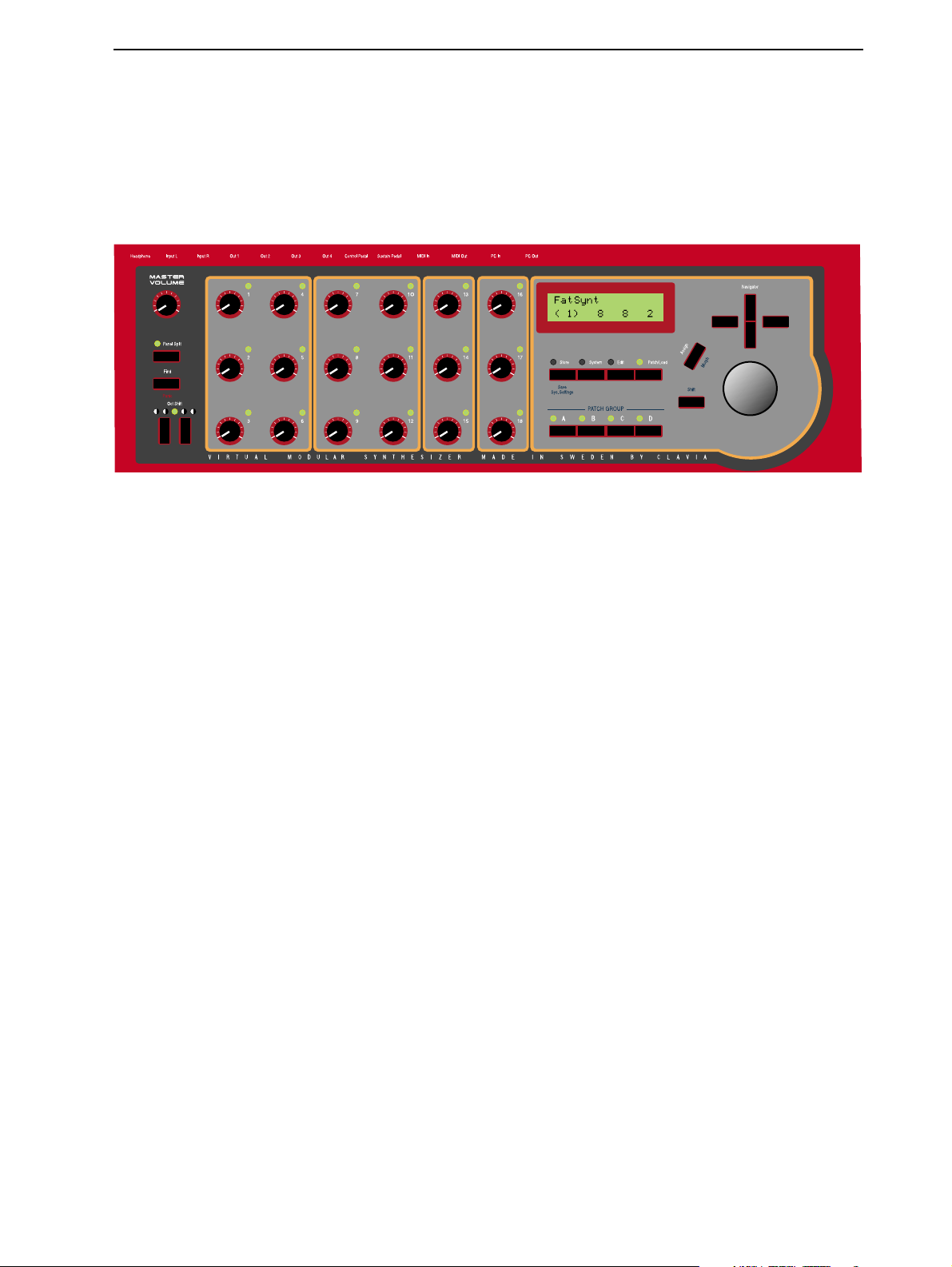
The
Pressing the
the Slots A, B, C and D.
The 18
trolled in real time. The
KKKK
You can quickly transpose Nord Modular keyboard in octave steps with the
settings that you make with these buttons will be saved together with the other parameters of the patch.
ASTER VOLUME
K
EEEEYYYYBBBBOOOOAAAARRRRDDDD
SSSSEEEECCCCTTTTIIIIOOOONNNN
P
ANEL SPLIT
NOBS
can each be assigned to a parameter in Nord Modular. These parameters can then be con-
VVVVEEEERRRRSSSSIIIIOOOONNNN
FFFF
RRRROOOONNNNTTTT
knob controls the level of the four
button assigns the 18
K
LED
NOB
PPPPAAAANNNNEEEELLLL
K
NOBS
(s) will be lit when a
O
UT
ports and the
in four separate groups, one group for each of
K
NOB
is assigned to a parameter.
H
EADPHONES
O
CT SHIFT
buttons. Any
output.
RRRR
The
RRRR
IIIIGGGGHHHHTTTT
The
thesis. The polyphony of the other active patches are shown without parenthesis.
The
The
The
The
internal memory to the slots.
The Slot buttons A, B, C and D activate the slots for playing and editing sounds.
The
The
The
The
AAAACCCCKKKK
VVVVEEEERRRRSSSSIIIIOOOONNNN
MIDI A
PPPPAAAANNNNEEEELLLL
D
ISPLAY
S
TORE
S
YSTEM
E
DIT
P
ATCH/LOAD
S
HIFT
A
SSIGN
N
AVIGATOR
R
OTARY DIAL
button allows you to store patches in Nord Modular.
button puts Nord Modular in Edit mode.
button activates a secondary function on some buttons.
CTIVE
light will flash when Nord Modular is receiving MIDI messages.
SSSSEEEECCCCTTTTIIIIOOOONNNN
shows the name of the active patch, and the polyphony of the selected patch within paren-
button gives you access to the Synth or Patch settings.
button activates the Patch mode, and is also used when patches are loaded from the
K
button lets you assign a parameter to one of the 18
buttons are used to scroll and select different functions in the menus.
is used to enter data.
NOBS
.
Page 3
Page 12
2. Overview NORD MODULAR V3.0
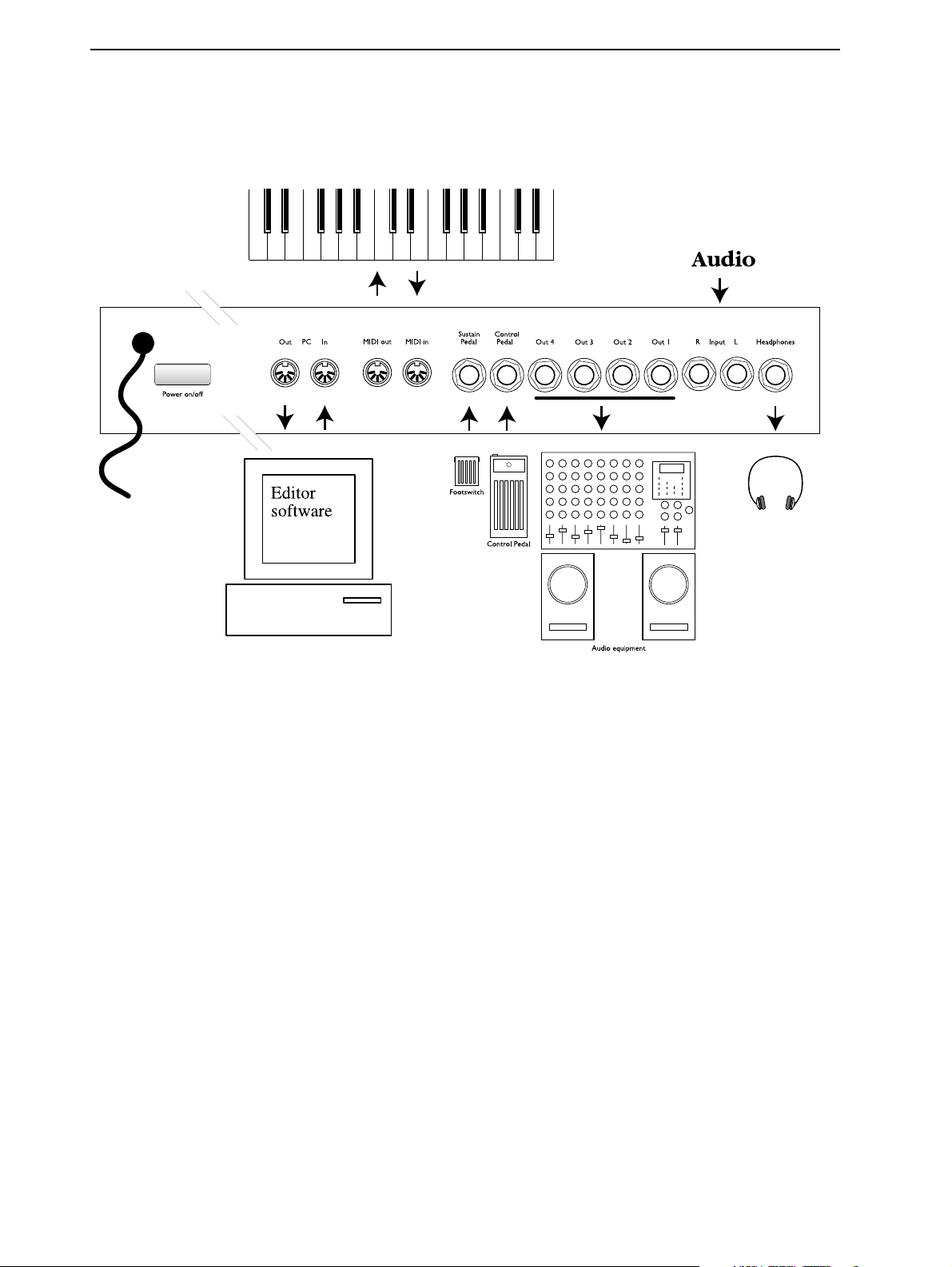
NNNN
OOOORRRRDDDD
M
M
OOOODDDDUUUULLLLAAAARRRR
M M
RRRR
EEEEAAAARRRR
P
P
P P
AAAANNNNEEEELLLL
P
Use the
Connect the MIDI Interface of the computer that runs the Editor software to the
ports.
Connect any external MIDI equipment to the
a master keyboard or another MIDI device.
Connect a footswitch to the
adjusted to suit different types of footswitches.
Connect an continuous control pedal to the
The audio outputs
Use
it will route the audio from
By connecting a sound source to the line level inputs
external sound sources and process in Nord Modular.
The
OWER ON/OFF
O
1
UT
if you are going to use Nor d Modular with a mono sound system. If only
H
EADPHONES
button to switch Nord Modular on and off.
M
IDI IN
S
USTAIN PEDAL
O
1-4
UT
route the audio signals from the four virtual mix buses in Nord Modular.
O
2
UT
as well.
output routes audio signals that are assigned to mix buses 1 and 2.
/ ON/OFF P
C
ONTROL PEDAL
I
and
NPUT
M
IDI OUT
EDAL
input. The polarity of the input can be
input.
L
and/or
ports. This could be a sequencer,
I
R
NPUT
, you can patch audio from
PC I
OUT 1
PC O
N
and
is connected,
UT
Page 4
Page 13
NORD MODULAR V3.0 2. Overview
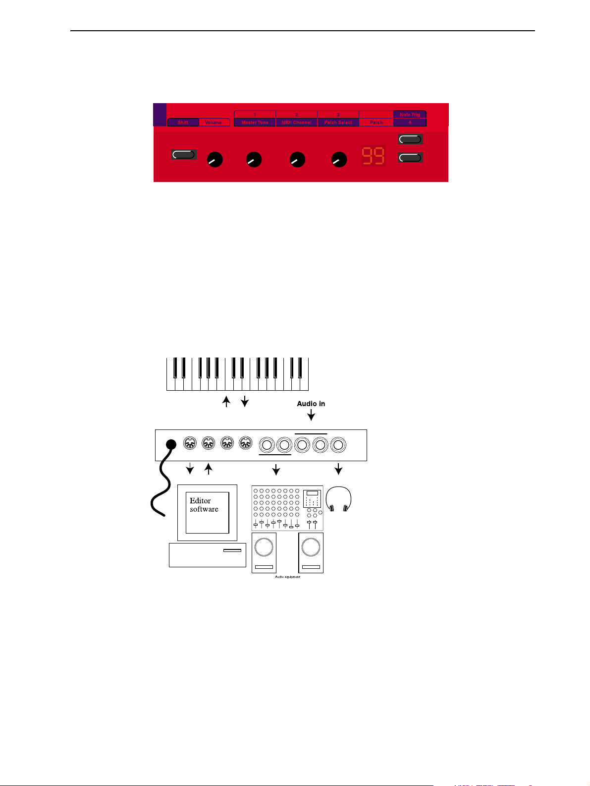
NNNN
NNNN
OOOORRRRDDDD
OOOORRRRDDDD
M
M
IIIICCCCRRRROOOO
M M
S
HIFT
The
The
The 3
be controlled in real time. If
Tune, MIDI Channel and Patch Selector.
The
The two buttons to the right are used for selecting patches. If
for trigging notes and the lower button can be assigned to a switch function in a patch.
button activates a secondary function on some buttons and knobs.
M
ASTER VOLUME
K
NOBS
D
ISPLAY
shows the patch number.
M
M
IIIICCCCRRRROOOO
M M
M
M
OOOODDDDUUUULLLLAAAARRRR
M M
knob controls the level of the two
can each be assigned to a parameter in Nord Micro Modular. These parameters can then
S
HIFT
is pressed, the assignable
M
M
OOOODDDDUUUULLLLAAAARRRR
M M
FFFF
RRRR
RRRROOOONNNNTTTT
EEEEAAAARRRR
PPPPAAAANNNNEEEELLLL
O
UT
ports and the
K
NOBS
have the following functions: Master
S
HIFT
is pressed, the upper button is used
PPPPAAAANNNNEEEELLLL
H
EADPHONES
output.
Connect the MIDI Interface of the computer that runs the Editor software to the
ports. Connect any external MIDI equipment to the
quencer, a master keyboard or another MIDI device.
O
1 & 2
The audio outputs
O
1
UT
Use
ed, it will route the audio from
By connecting a sound source to the line level inputs
external sound sources and process in Micro Modular.
The
if you are going to use Micro Modular with a mono sound system. If only
H
EADPHONES
UT
output routes audio signals that are assigned to mix buses 1 and 2.
route the audio signals from the four virtual mix buses in Micro Modular.
O
2
UT
as well.
I
M
IDI IN
NPUT
L
and
and/or
M
IDI OUT
I
NPUT
ports. This could be a se-
R
, you can patch audio from
PC I
N
and
OUT 1
PC O
UT
is connect-
Page 5
Page 14

3. Getting started NORD MODULAR V3.0
3. G
3. G
3. G3. G
EEEETTTTTTTTIIIIN
NG
NN
G
GG
S
STTTTAAAARRRRTTTTEEEED
SS
D
DD
EEEE
DDDDIIIITTTTOOOORRRR
The Editor software requires a PC running Windows 95/98/NT4.0 (a Pentium 133 MHz or better is
recommended) or a Macintosh PowerPC running Mac OS 8.6 or later (a 120 MHz PowerPC or better
is recommended), with a CD ROM drive and a mouse. The computer has nothing to do with the actual
sound processing in Nord Modular - it is used only for visual patching and to send instructions to Nord
Modular. The Editor is designed for minimum 800 x 600 pixels screen area but 1024 x 768 is recommended, and minimum 16-bit color (thousands). The computer must be equipped with a MIDI interface with previously installed driver routines. The Macintosh version of the Nord Modular Editor
requires OMS, which must be installed and activated on your Mac.
IIII
NNNNSSSSTTTTAAAALLLLLLLLAAAATTTTIIIIOOOONNNN
OOOO
NNNN
1. Insert the Editor installation CD into the CD-ROM drive.
2. Select Start|Run from the Windows taskbar. Type d:\Modular3.exe and press Enter (if your CD unit
3. After the initial setup is complete, the Welcome window will appear. Click on the Next button when
SSSSYYYYSSSSTTTTEEEEMMMM
PC
PC
PC PC
has another device letter, type that one instead of ‘d’). The setup program will start.
you are ready to move on with the installation. The Editor software will be installed in a folder
named Clavia in the Program Files folder, on the hard disk. During the installation you will be able
to select an alternative location for the software.
RRRREEEEQQQQUUUUIIIIRRRREEEEMMMMEEEENNNNTTTTSSSS
OOOOFFFF
TTTTHHHHEEEE
EEEE
DDDDIIIITTTTOOOORRRR
SSSSOOOOFFFFTTTTWWWWAAAARRRREEEE
4. Confirm every window in the installation procedure by clicking on the Next button. The installation
may be aborted by clicking on Cancel.
5. When the installation is complete, click on Finish and the computer will return to the Windows
desktop.
OOOO
M
M
NNNN
AAAACCCC
M M
1. Insert the Editor installation CD into the CD-ROM drive.
2. Drag the files ‘Modular Editor 3.0’, ‘Modular Update 3.0’ and ‘Micro Update 3.0’ to the hard disk.
The ‘Modular Editor 3.0’ file is the Editor file for both Nord Modular and Micro Modular. ‘Modular Update 3.0’ is the update file for the Nord Modular synthesizer and ‘Micro Update 3.0’ is the
update file for the Micro Modular synthesizer. Drag the update file(s) you need for your specific synthesizer model.
3. Double-click on the update file for your synthesizer model and follow the instructions.
Page 6
Page 15
NORD MODULAR V3.0 3. Getting started
4. When the installation of the synthesizer Update is complete, you are set to start the Modular Editor
3.0 program.
SSSS
TTTTAAAARRRRTTTTIIIINNNNGGGG
Make all the audio connections before turning on any of the devices. The computer that runs the Editor
must be connected to both
Note! You cannot use the Editor software and the Nord Modular PC ports in a traditional MIDI setup, using MIDI THRU-boxes or MIDI THRU connections on other instruments. The Nord Modular
PC ports have to be used exclusively for the Editor software on the computer.
USB MIDI
USB MIDI
USB MIDI USB MIDI
UUUUPPPP
PC I
Nord Modular Micro Modular
IIIINNNNTTTTEEEERRRRFFFFAAAACCCCEEEESSSS
N
and
PC O
UT
of Nord Modular.
OR
MMMM
AAAACCCCIIIINNNNTTTTOOOOSSSSHHHH
USB MIDI interfaces sometimes have problems handling MIDI data when AppleTalk is activated.
Therefore, if you are experiencing communication problems when using a USB MIDI interface, disable
AppleTalk.
MMMM
UUUULLLLTTTTIIIIPPPPOOOORRRRTTTT
The Editor needs a separate MIDI port (1 MIDI In and MIDI Out pair) for each connected Nord Modular/Micro Modular to run properly. If you are using several Modulars and/or a sequencer software on
the same computer as the Editor, you will need a multiport MIDI interface. You must configure the Editor and the sequencer to use separate ports of the multiport MIDI interface.
Most of the sequencer software automatically opens every port of a multiport interface. In this case
you have to deassign one or more of the ports in the sequencer software and dedicate them exclusively
to the Editor. See the MIDI setup/configuration/devices part in the sequencer program manual.
MMMM
AAAACCCCIIIINNNNTTTTOOOOSSSSHHHH
If you want to run one or several MIDI applications at the same time with the Editor, make sure you have
selected ‘MIDI in background’ in the OMS setup.
MIDI
MIDI
MIDI MIDI
OMS
OMS
AAAANNNNDDDD
OMS OMS
IIIINNNNTTTTEEEERRRRFFFFAAAACCCCEEEESSSS
Page 7
Page 16

3. Getting started NORD MODULAR V3.0
SSSS
OOOOUUUUNNNNDDDD
Connect the desired outputs of Nord Modular/Micro Modular to a sound system. We suggest that you
start with connecting output 1 to a left channel and output 2 to a right channel of the sound system. Turn
on Nord Modular first, followed by the sound system.
LLLL
AAAAUUUUNNNNCCCCHHHHIIIINNNNGGGG
SSSSYYYYSSSSTTTTEEEEMMMM
Nord Modular
TTTTHHHHEEEE
E
E
E E
OR
Micro Modular
DDDDIIIITTTTOOOORRRR
1. On PC: from the Start menu in the Windows taskbar, select Programs|Nord Modular 3|Editor. On
Mac: double-click on the Editor icon in the Modular 3 folder in the Program Files folder. During
the start-up procedure, the Editor software will search for the Nord Modular synthesizer(s). The very
first time you launch the Editor, you need to tell it which MIDI port(s) to use for communication
with the Nord Modular synthesizer(s).
2. In the Setup drop down menu, select MIDI.
Check in the Enabled box for Port 1. If the MIDI interface driver(s) have been properly installed, you
will be able to select a MIDI port in the In- and Out dropdown lists. Up to four Nord Modular synthe-
Page 8
Page 17
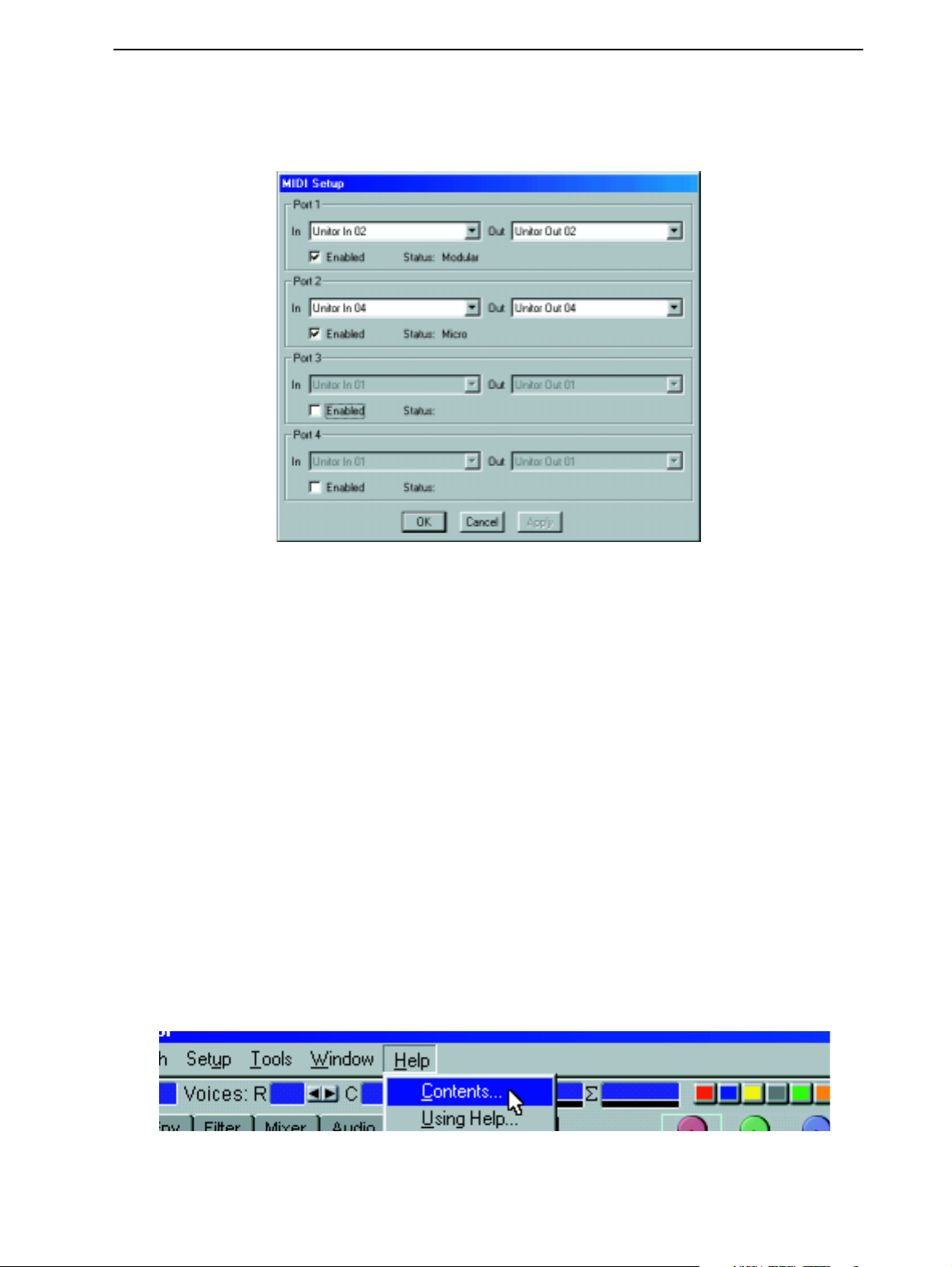
NORD MODULAR V3.0 3. Getting started
sizers are supported by the Editor. If you use several Nord Modular synthesizers, repeat the procedure for
the following Ports.
If the Nord Modular synth is not turned on, or if the connection between Nord Modular and the computer is not working properly, an error message will appear. In that case, check the MIDI connections
and cables, make sure that the MIDI interface is properly installed and working, and that Nord Modular
is turned on. Click on the Apply button. When the Editor has found the Nord Modular synth, the Name
of the connected synth is shown in the Status line.
When you’re satisfied with the port selection, click OK. The port selection is automatically saved in the
Editor, so the next time you start the Editor, you don’t have to redo the selection. If ‘Auto Upload’ is
TTTTHHHHEEEE
S
LOT
will automatically upload
E
E
DDDDIIIITTTTOOOORRRR
E E
activated, which is the default setting in the Editor, the patch of the active
and open in the patch window.
Note! Each time you start the Editor and establish contact with the Nord Modular, information about
all patches stored in the internal memory of the synthesizer will be sent from the synthesizer to the
Editor. This will take a couple of seconds depending on how many patches are stored in the synthesizer. During this information transmission, the regular communication between the synthesizer and Editor will be slower.
HHHH
EEEELLLLPPPP
FFFFIIIILLLLEEEESSSS
The PC version of the Editor comes with an extensive help section. To access the Help files, select Contents from the Help menu. Every module and module parameter has its own pointer to the Help file. The
Help files can be accessed with the F1 key or by right-clicking on a module or parameter and selecting
Help. Note that Help files are only available in the Windows version of the Editor.
IIIINNNN
TTTTHHHHEEEE
PC
PC
PC PC
VVVVEEEERRRRSSSSIIIIOOOONNNN
OOOOFFFF
Page 9
Page 18
3. Getting started NORD MODULAR V3.0
LLLL
OOOOAAAADDDDIIIINNNNGGGG
A patch in Nord Modular can be considered the same as a “sound”, even though a patch is an entire synthesizer configuration that can often produce much more than just a single sound, but we will return to
that later. Nord Modular has an internal memory of up to 9 banks (1-9), each containing up to 99 (1-
99) memory locations. It’s not likely that you will be able to fit in 9 x 99 patches at the same time in the
internal memory. The total number of patches that can be stored in the internal memory depends on the
patches’ size. Thanks to the advanced compression, the internal memory can hold several hundreds of
patches (one bank of 99 patches is maximum in Micro Modular). A patch always has to be loaded to a
S
LOT
NNNN
OOOORRRRDDDD
1. Activate a slot with one of the four slot buttons (A-D) on the Nord Modular front panel. The corre-
sponding LED starts flashing.
2. Press the
AAAA
PPPPAAAATTTTCCCCHHHH
(A, B, C or D of Nord Modular) before it can be played. This is how you do:
M
M
OOOODDDDUUUULLLLAAAARRRR
M M
P
ATCH/LOAD
FFFFRRRROOOOMMMM
button on the panel. The
TTTTHHHHEEEE
IIIINNNNTTTTEEEERRRRNNNNAAAALLLL
P
ATCH/LOAD
LED starts flashing
MMMMEEEEMMMMOOOORRRRYYYY
3. Select desired bank with the Up and Down
a patch to load. The names and locations of the patches appears in the
scroll through the entire internal memory using only the
of course.)
xxx Patch Name
Load?
Page 10
N
AVIGATOR
buttons. Turn the
D
ISPLAY
R
OTARY DIAL
, but it will take a little longer
R
OTARY DIAL
. (It’s possible to
and select
Page 19
NORD MODULAR V3.0 3. Getting started
P
4. Load the patch by pressing the
slot. The number within parenthesis indicates the current polyphony of the patch.
ATCH/LOAD
button again. The patch is now loaded in the active
Patch Name
( 4) -- -- --
It is not necessary to have the instrument connected to the computer if you only want to play the patches
from the internal memory or change module parameter values. The computer and Editor is needed only
when you want to add or remove modules in a patch, change “cable” connections in a patch or create new
patches.
MMMM
IIIICCCCRRRROOOO
Micro Modular has only got one slot to load a patch into, and it’s always active. The patch number shown
in the
or lower button to the right of the
It is not necessary to have the instrument connected to the computer if you only want to play the patches
from the internal memory or change the assigned module parameter values.
CCCC
RRRREEEEAAAATTTTIIIINNNNGGGG
When you want to create new patches in Nord Modular you always have to do this in the Editor software
on the computer. In this example you will create a basic synthesizer patch. Open the Modular Editor
V3.0 on your computer. Make sure the Editor has established contact with your Nord Modular synthesizer. If it hasn’t, please see “Launching the Editor” on page 8.
1. In the File menu, select New.
M
M
M M
D
ISPLAY
OOOODDDDUUUULLLLAAAARRRR
is always active and ready to be played and edited. To select patches, either press the upper
AAAA
PPPPAAAATTTTCCCCHHHH
D
ISPLAY
FFFFRRRROOOOMMMM
, or press
S
HIFT
and turn
SSSSCCCCRRRRAAAATTTTCCCCHHHH
K
3
NOB
(Patch Select).
Page 11
Page 20
3. Getting started NORD MODULAR V3.0
2. The “Slot Selection” dialog box appears. In this example, select slot B. Click OK. A new, empty
patch window appears. If you use Micro Modular, the dialog box looks a bit different. Select “Slot”
and click OK.
3. An empty Patch window is opened. The Patch window is divided into two sections: the Poly Voice
Area at the top and the Common Voice Area at the bottom of the Patch window. The difference
between these areas will be explained later in this example. We will begin using the upper section, the
Poly Voice Area.
4. Locate the Module tabs in the upper left part of the patch window (In/Out, OSC, LFO etc.). Select
the In/Out tab. A brief description appears when you place the cursor over a module icon (PC version only). The % figure indicates how much Sound engine power (Load) the module will use
5. Click-drag one ‘Keyboard - voice’ module and one ‘1Output’ module to the Poly Voice Area. As you
will notice, the modules will self-align when placed near each other. It doesn’t matter where in the
Poly Voice Area you put your modules, but a good idea is to place them in a “natural” flow so it
becomes easier to follow the signal paths visually.
6. Click on the Osc tab, and click-drag one ‘OSCA’ module to the Poly Voice Area.
7. Click on the Env tab and click-drag one ‘ADSR envelope’ to the Poly Voice Area.
Page 12
Page 21
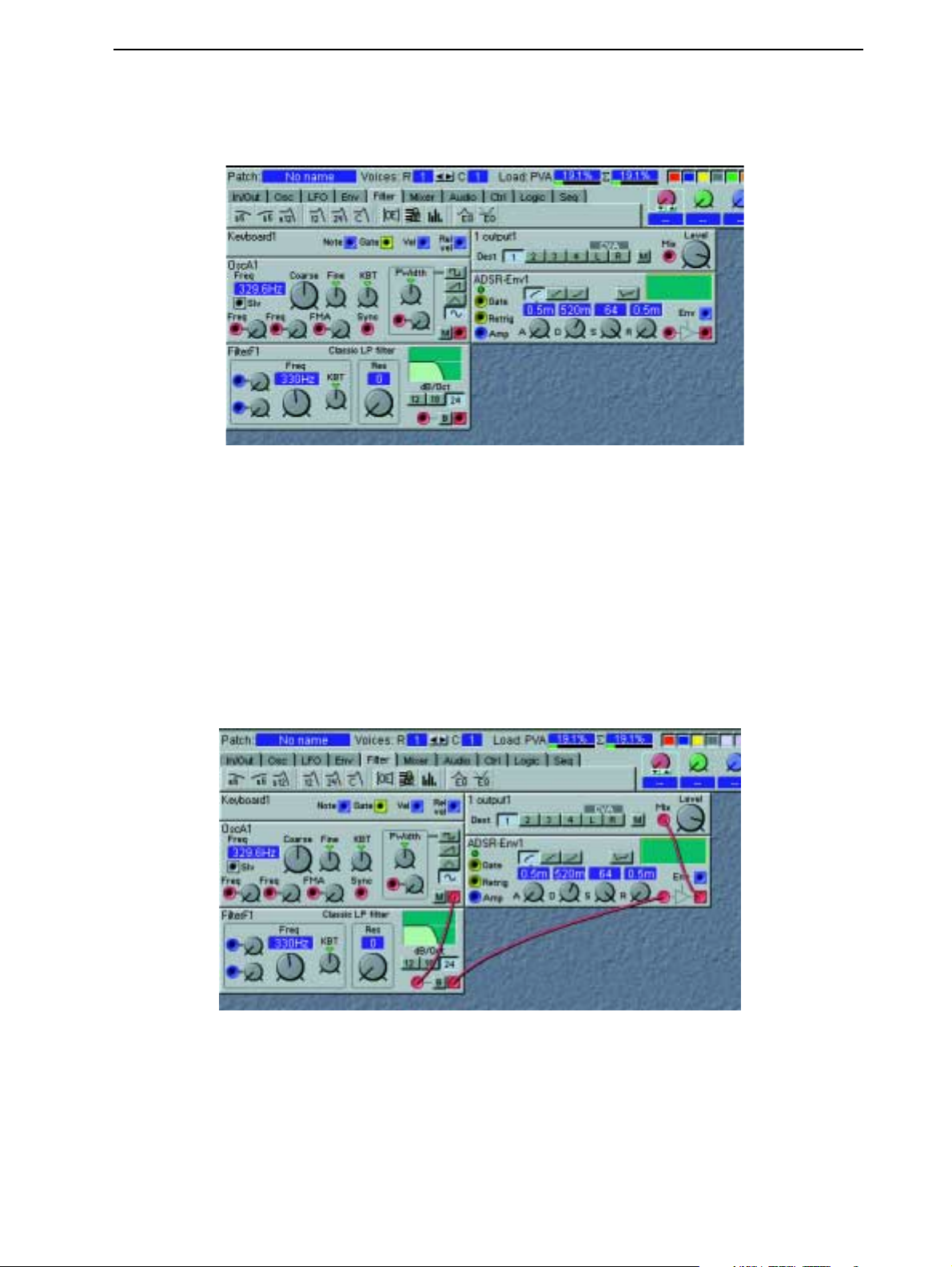
NORD MODULAR V3.0 3. Getting started
8. Click on the Filter tab and click-drag one ‘24 dB classic filter’ to the Poly Voice Area. Now your
patch should look something like this:
9. Let’s settle with these modules for now and start with the cable connections. First of all, let’s connect
all audio cables between the modules: Place the cursor over the red square output of the ‘OscA1’
module. Click, hold and drag the cursor to the red circular input of the ‘FilterF1’ module. Release
the mouse button. Now, a red audio cable appears between the two modules. Repeat the procedure
and connect the ‘FilterF1’ output to the ‘ADSR-Env1’ input and the ‘ADSR-Env1’ output to the ‘1
output1’ input.
If you should accidentally connect wrong, simply double-click-hold on one of the connectors, drag
the cable away from the connector, and release the mouse button. The cable disappears.
Finally, click on Destination button 1 of the ‘1 output1’ module to route the audio signal to the phys-
O
ical
1
UT
jack of Nord Modular. Your patch should now look like this.
10. Even though all audio cables have been properly connected, no sound is heard. You have to make the
envelope generator “open up” for the audio signal. Place the cursor on the yellow Voice gate output
Page 13
Page 22
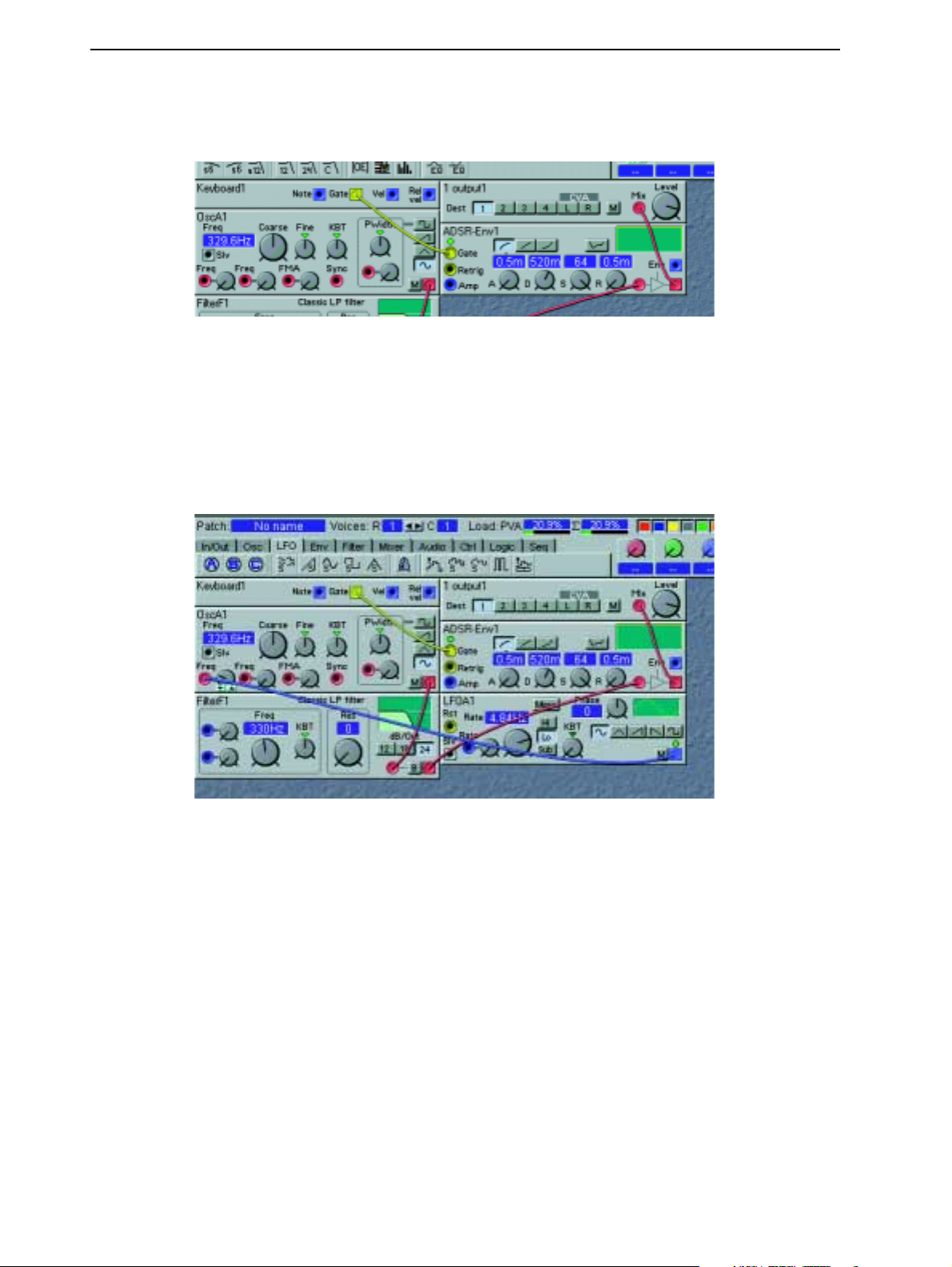
3. Getting started NORD MODULAR V3.0
of the Keyboard Voice module. Click and drag the cursor to the yellow Gate input of the ‘ADSREnv1’ module.
A yellow cable appears between the two connections. If you play on Nord Modular (via the keyboard
MIDI I
or
11.Now, let’s add an ‘LFOA’ module from the LFO tab to the patch. Connect a cable between the
square, blue output of the ‘LFOA1’ module, to the red, circular Pitch input of the ‘OscA1’ module.
Play the Nord Modular and turn the Pitch input attenuator knob next to the input of ‘OscA1’ by
click-holding and moving the mouse. This makes ‘LFOA1’ modulate the pitch of the oscillator, adding vibrato to the patch. Your patch should look something like this:
N
), the envelope Gate LED lights up and the patch will sound.
If you like, you can connect a new cable from the Pitch input of the ‘OscA1’ module, to the circular,
red input in the Pulse Width section, located to the right in the same module. This will route the LFO
to both the Pitch and the PWM inputs. Select the square wave on the oscillator waveform selector and
turn up the modulation attenuator knob, next to the PWM input. Also, increase the cutoff frequency
of the ‘FilterF’ a bit to make the sound brighter. (One single modulator can be connected to several
different destinations, either by making a “branch connection” from the original output to every input, or by making a serial connection from the first input to the second input, to the third etc.)
12.Now that we are satisfied with the modules and connections, let’s make the patch polyphonic. Since
all modules are used in the Poly Voice Area, it is possible to play the patch polyphonically. Locate the
Voices buttons, to the right of the Patch name display box in the toolbar. Set the requested number
Page 14
Page 23

NORD MODULAR V3.0 3. Getting started
of voices by clicking on the right arrow button. In the C display box, the current number of voices
for the patch is shown. In this example, we request 4 voices.
13.In the bottom section of the patch window, the Common Voice Area, you can place modules that
should act equally on all voices in the patch. Modules used in the Common Voice Area will act on
the sum of the signals from the Poly Voice Area. Let’s say we want a stereo chorus acting on all voices
in our sound, but we don’t want the stereo chorus module to be duplicated for each voice like the
other modules. First we need to tell the ‘1 output1’ module in the Poly Voice Area to route the signal
O
to the Common Voice Area instead of the physical
the CVA L destination button on the module. Click on the In/Out tab and click-drag one ‘Poly Area
In’ module and one ‘2 Outputs’ module to the Common Voice Area. Click on the Audio tab and
click-drag one ‘Stereo chorus’ module to the Common Voice Area. Your patch will now look like
this:
1
UT
of the Nord Modular. Do this by clicking
14.Now, connect the red L audio output of the ‘Poly Area In’ module to the red circular input of the
‘Stereo chorus’ module. Then, connect the two outputs of the ‘Stereo chorus’ module to the inputs
of the ‘2 Outputs’ module. As you play, you can see the LED chain of the ‘Poly Area In’ module display the signal level from the Poly Voice Area. If you need to, increase the level on the ‘1Output’
Page 15
Page 24
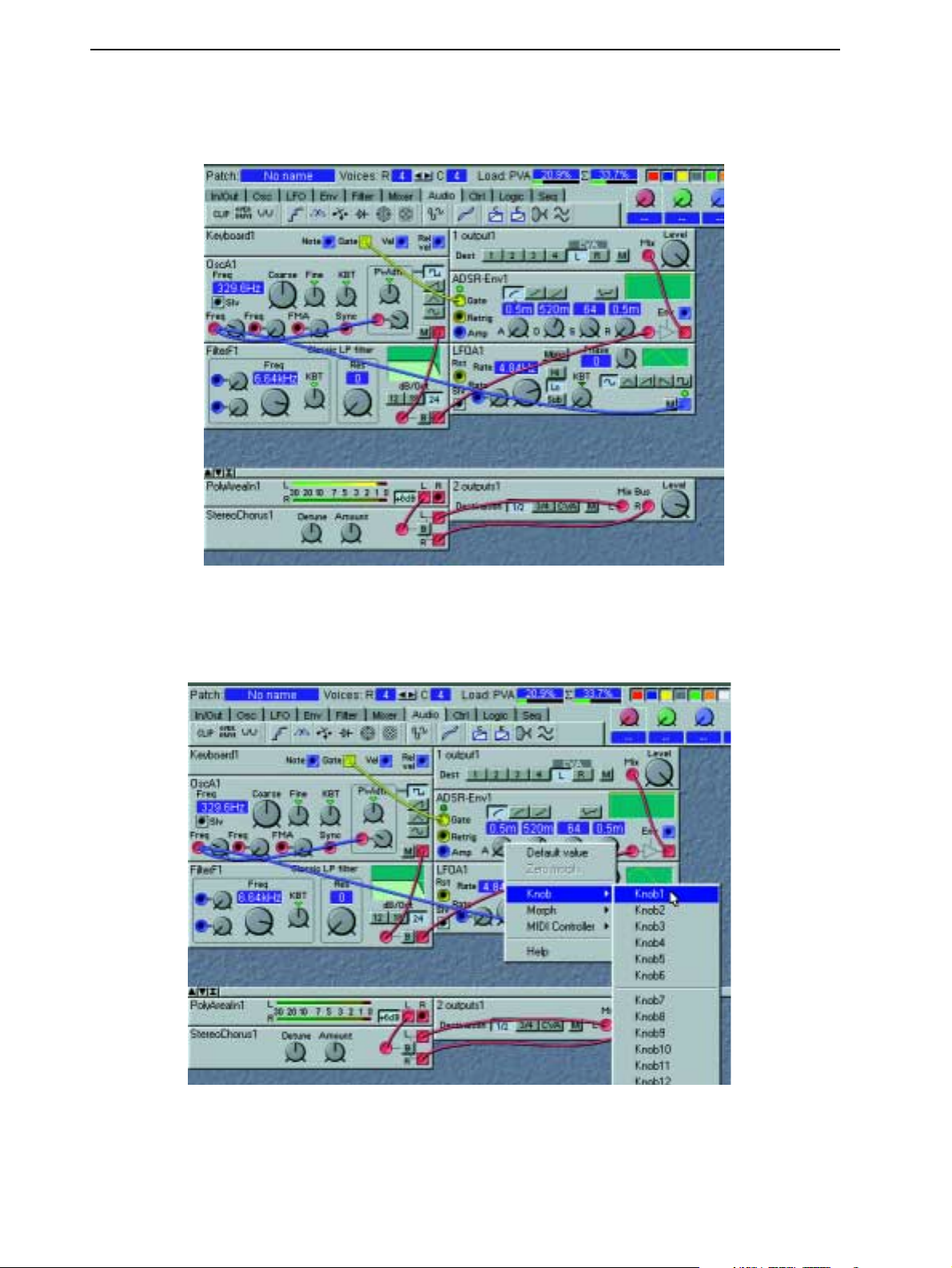
3. Getting started NORD MODULAR V3.0
module in the Poly Voice Area, and click the +6dB button on the ‘Poly Area In’ module to amplify
the signal even more.
15.Finally, to make the patch editable and controllable from the Nord Modular front panel, you can
assign any parameter in the patch to any of the 18
K
NOBS
of Nord Modular (3
K
NOBS
+ 1 button
on Micro Modular). Simply right[PC]/Ctrl[Mac]-click on a module parameter, for example, the
K
Attack knob of the ‘ADSR-Env’ module, and select which
NOB
to assign it to.
Page 16
Page 25
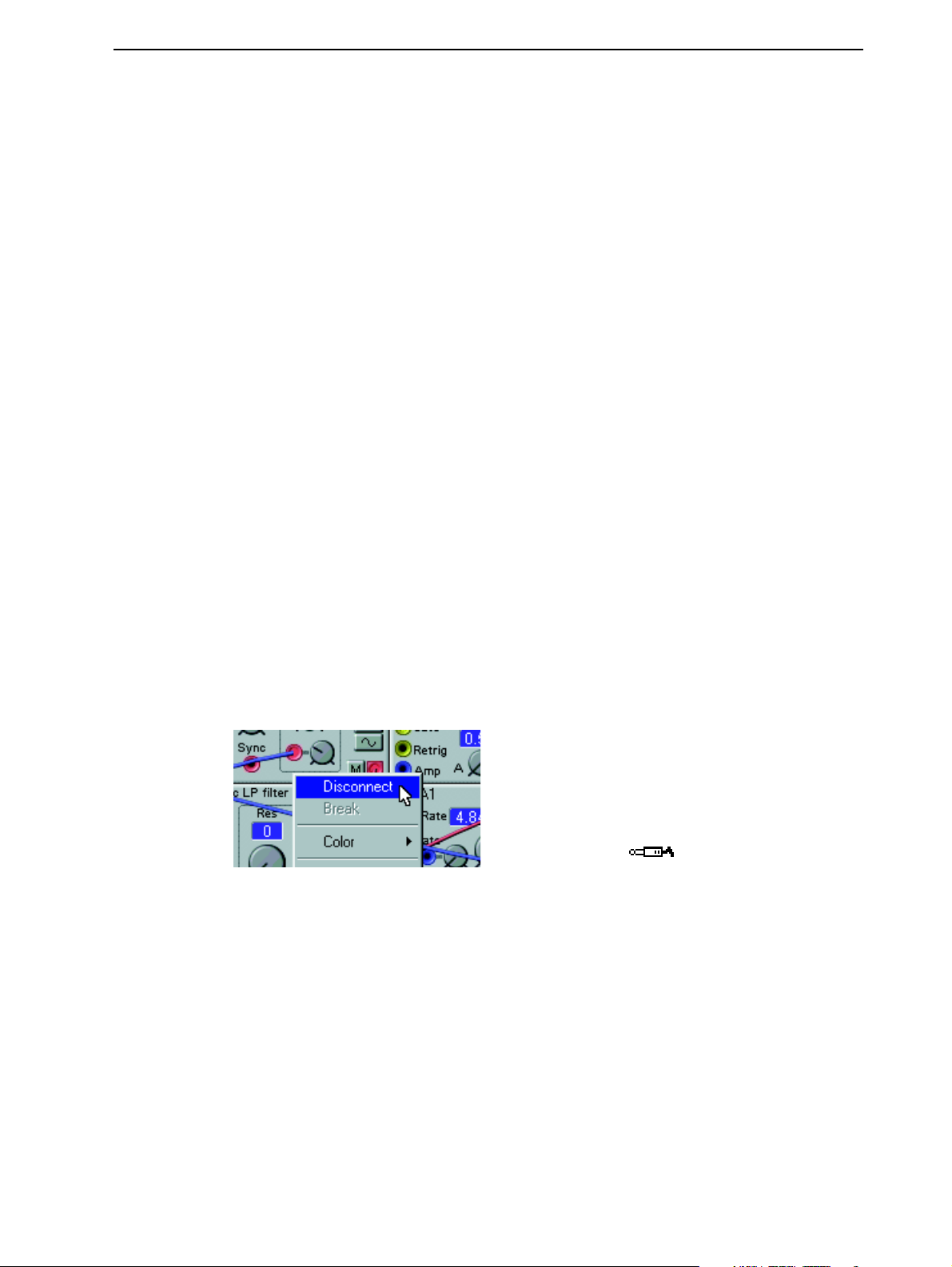
NORD MODULAR V3.0 3. Getting started
Let’s say you want to assign the ‘ADSR-Env’ Attack to
K
NOB
1. Now, when turning
K
NOB
synthesizer front panel, the attack time will change. Proceed with the knob assigning until you are sat-
K
isfied. Note that you can also assign
form selector of ‘OscA’, the dB selector of ‘FilterF’ etc. You can deassign any of the
NOBS
to selector switch parameters (buttons), such as the wave-
K
NOBS
right[PC]/Ctrl[Mac]-clicking on the parameter and choosing No Knob from the knob popup. You
can also reassign a parameter to another knob by right[PC]/Ctrl[Mac]-clicking and selecting an unused knob number.
16.To (re)name the patch, click on the Patch display box to the upper left of the toolbar and enter a
patch name. Press Enter on the computer keyboard and the patch name is changed in the Editor and
D
in the
File menu.
ISPLAY
(not on Micro Modular). Save your patch on the computer using Save As from the
Note! patches that are saved from a PC Editor automatically gets the extension ‘.pch’.
For patches saved in a Mac Editor to be readable in a PC Editor, you must manually type in the
extension ‘.pch’ in the file name.
To save the patch in the memory of Nord Modular (and Micro Modular), select Tools|Browser.
Right[PC]/Ctrl[Mac]-click on a patch or a bank in the Synth tab and select ‘Save Slot B To:...’.
that the original patch in the selected memory location will be overwritten by your new patch.
Make sure you do not overwrite patches you want to keep! It is a good idea to save a backup of all
your patches on the computer, just in case.
OOOO
TTTTHHHHEEEERRRR
UUUUSSSSEEEEFFFFUUUULLLL
FFFFUUUUNNNNCCCCTTTTIIIIOOOONNNNSSSS
1 on the
by
Note
RRRR
EEEEMMMMOOOOVVVVEEEE
CCCCAAAABBBBLLLLEEEESSSS
To remove a cable, right[PC]/Ctrl[Mac]-click on a connection (input or output) and select Disconnect,
or double-click-hold or Ctrl[PC]/Alt[Mac]-click on a connection (an extra wire appears next to the connector cursor) and “pull out” the connector by dragging the connector symbol away from the input/output and release the mouse button.
right[PC]/Ctrl[Mac]-click OR Double-click or Ctrl[PC]/Alt[Mac]-click
MMMM
OOOOVVVVEEEE
MMMMOOOODDDDUUUULLLLEEEESSSS
You can move the modules in the patch window by click-holding its gray “panel” and move the frame
that appears. Other modules will move if you drop a module onto another. You can also move several
modules at the same time by placing the cursor on the patch window background and click-hold and select the modules you want to move. The names of the selected modules are highlighted to indicate that
they have been selected.
DDDD
EEEELLLLEEEETTTTEEEE
MMMMOOOODDDDUUUULLLLEEEESSSS
To delete a module from a patch, either click on the module background and press the Delete key on the
computer keyboard or select Clear from the Edit menu. Alternatively, right[PC]/Ctrl[Mac]-click on the
Page 17
Page 26
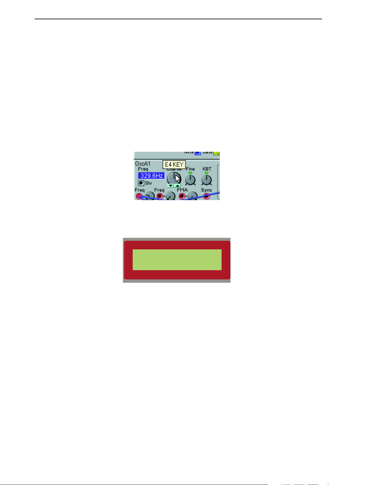
3. Getting started NORD MODULAR V3.0
module background and select Delete from the popup. Please note that all cable connections made to the
module will also be deleted or re-routed. You can also delete several modules by selecting them as described in the example above. Then, either press the Delete key, select Clear from the Edit menu or
right[PC]/Ctrl[Mac]-click on one of the selected modules and choose Delete from the popup.
UUUUTTTT
AAAA
PPPPAAAARRRRAAAAMMMMEEEETTTTEEEERRRR
PPPP
Putting parameters in focus is possible only if the patch is active in the synthesizer. Put a parameter in
focus by clicking on it. An increment and decrement button appears below the knob/slider parameter as
you move the cursor over it, and the current setting of the parameter displays briefly in a yellow hintbox.
When you click on the parameter, the increment/decrement buttons (or button selectors) are highlighted.
To edit the parameter value, you can click-hold the parameter and move the mouse. Click on the increment and decrement buttons to change the value one step at a time. You can also use the computer keyboard + and - keys to increase and decrease the focused parameter value.
“
“
“ “
IIIINNNN
FFFFOOOOCCCCUUUUSSSS
””””
Press the
in the Editor will also appear in the
the
E
DIT
R
OTARY DIAL
button on the Nord Modular front panel (not Micro Modular). The parameter “in focus”
D
ISPLAY
and you can now change the value of the parameter with
.
OscA1
Freq coars: E4k
R
Play on Nord Modular and turn the
The Editor will echo any adjustments that you make from
panel.
N
Press the left or right
PLAY
will display the same parameter that appears on the computer screen.
DDDDIIIITTTT
AAAA
FFFFAAAACCCCTTTTOOOORRRRYYYY
EEEE
AVIGATOR
PPPPAAAATTTTCCCCHHHH
If you want to edit a factory patch from the instrument’s internal memory, load the desired factory patch
S
into a
LOT
in Nord Modular. In Micro Modular, select a patch with the Patch selector buttons. A new
patch window will be created in the Editor containing the patch of the active
gets the same name as the patch in the uploaded
OTARY DIAL
to instantly hear what is happening with the sound.
R
OTARY DIAL
on the Nord Modular front
buttons to change the parameter “focus” within the module. The
S
LOT
. The patch window
S
LOT
when saved to disk.
D
IS
-
Page 18
Page 27

NORD MODULAR V3.0 4. Basic functions
4. B
4. B
4. B4. B
IIIINNNNTTTTRRRROOOODDDDUUUUCCCCTTTTIIIIOOOONNNN
A modular synthesizer could be described as a flexible electronics kit. It contains a lot of parts, the modules, which have various functions. You can build your own, customized synthesizer by connecting different modules and functions with patch cables. A modular synthesizer has the advantage of being a very
flexible instrument, leaving you in charge of the routing of the signals and functions in the synth. Nord
Modular takes this concept several steps further, being programmable, polyphonic, and multitimbral.
Nord Modular also features a very powerful editing system in the supplied Editor software.
MMMM
OOOODDDDUUUULLLLEEEESSSS
A module in Nord Modular can be, for example, an oscillator, an envelope generator, a filter or a step
sequencer. There are over 100 different types of modules available in Nord Modular, and the number is
constantly increasing with software updates. You are not limited to use only one module of a specific type
in a patch. Several identical modules can be used together, creating, for example, really fat multi-oscillator
patches.
AAAASSSSIIIICCCC
TTTTOOOO
FFFFU
UN
UU
N
N
N N
NCCCCTTTTIIIIO
NN
M
OOOORRRRDDDD
M
M M
ON
OO
OOOODDDDUUUULLLLAAAARRRR
NSSSS
NN
CCCC
OOOONNNNNNNNEEEECCCCTTTTIIIIOOOONNNNSSSS
Every module and nearly every function of a module can be patched to other modules and functions, using virtual cables. Each module has one or more connectors. These connectors come in two different
shapes: circular inputs and square outputs, and four different variants: red audio-, blue control-, yellow
logic- and gray slave-connectors. Most of the modules share the same basic layout, with the input connector(s) to the left and the output connector(s) to the right.
PPPP
AAAARRRRAAAAMMMMEEEETTTTEEEERRRRSSSS
There are usually one or more parameters on each module. A parameter could be a knob, a slider or a
selector switch (button). You change the setting of a parameter either with the mouse in the Editor soft-
K
ware, with an assigned
parameter in the Editor is “turned” by click-holding it and moving the mouse. Click on the increment
and decrement buttons to change the value one step a ta time. You can also use the computer keyboard
+ and - keys to increase and decrease the focused parameter value. A selector switch is toggled by clicking
on it.
DDDD
IIIISSSSPPPPLLLLAAAAYYYY
Some modules feature one or more display boxes that display alphanumeric and/or graphical information. Some oscillator modules, for example, display the frequency. The read-out of the oscillators is selectable between Hz and semitones, by clicking on the display window. Graphical information in
modules can be envelope curves, wave shapes, frequency diagrams etc.
BBBBOOOOXXXXEEEESSSS
NOB
AAAANNNNDDDD
on the front panel or with the
GGGGRRRRAAAAPPPPHHHHSSSS
R
OTARY DIAL
(not Micro Modular). A knob
LED
LED
LEDLED
SSSS
Some modules have one or several LEDs to indicate functions. The rate of an LFO, the opening or closing
of an envelope or the current step position in a sequencer module are some examples of where LEDs are
used.
Page 19
Page 28
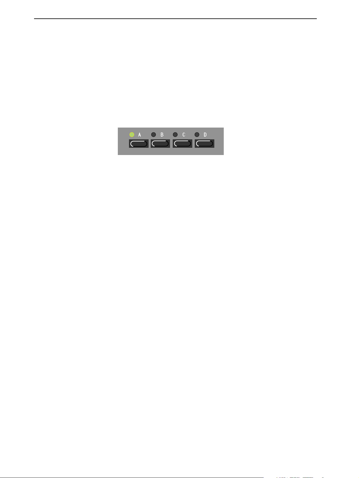
4. Basic functions NORD MODULAR V3.0
TTTT
HHHHEEEE
PPPPAAAATTTTCCCCHHHH
When you have connected a couple of modules together, you have created a patch. A patch can be saved
on the computer and/or stored in the Nord Modular internal memory. A patch can produce one particular sound, or several sounds at once, depending on how many sound sources you use in the patch. A
patch could be anything from a copy of an existing vintage synthesizer, to a completely unique synthesizer
configuration of your own design.
SSSS
LLLLOOOOTTTTSSSS
There are four
A
You activate a
above the
name of the patch and the
By pressing
the active
PPPP
(
(
( (
S
LOT
can be considered as a temporary memory location which can hold a patch for playing or editing.
LLLLAAAAYYYYIIIINNNNGGGG
M
M
NNNNOOOOTTTT
S
LOT BUTTON
S
S
LOT
MMMMUUUULLLLTTTTIIIITTTTIIIIMMMMBBBBRRRRAAAALLLLLLLLYYYY
IIIICCCCRRRROOOO
M M
S
LOTS
labelled A, B, C and D, in Nord Modular. You can load one patch to each slot.
S
LOT
by pressing one of the
will flash green to indicate that the
HIFT
while turning the
.
M
M
OOOODDDDUUUULLLLAAAARRRR
M M
current
))))
S
LOT BUTTONS
number of voices assigned to the patch within parenthesis.
R
OTARY DIAL
on the Nord Modular front panel. The
S
LOT
is active. The
D
ISPLAY
shows the
, you can change the number of requested voices for
The slots can receive MIDI information on separate MIDI channels, making Nord Modular multitimbral. If you want to use Nord Modular multitimbrally you first have to load the patches you want in each
S
LOT
. Then, simultaneously press the
TONS
have been pressed, the active
You can change the active slot by pressing the corresponding
slots in a multitimbral setup, press
S
LOT BUTTONS
S
LED
LOT
S
HIFT
and the desired
for the slots you want to use. If several
will flash, the others will be solid green.
S
LOT BUTTON
S
LOT BUTTON(S
. To deactivate and reactivate
)
D
. The
ISPLAY
S
LOT BUT
shows the
name of the patch in the active slot and the current number of voices of that patch within parenthesis.
D
The other numbers in the
ISPLAY
show the current number of voices assigned to the other patches in
the setup.
LED
-
By pressing
the active
Page 20
S
S
HIFT
while turning the
LOT
.
R
OTARY DIAL
, you can change the number of requested voices of
Page 29
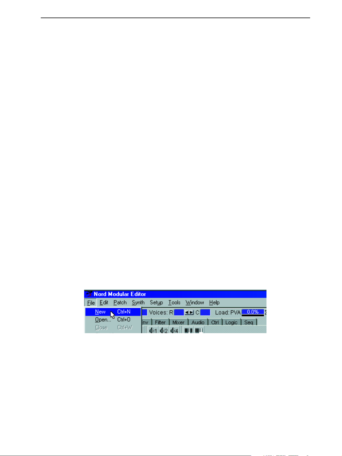
NORD MODULAR V3.0 4. Basic functions
PPPP
AAAATTTTCCCCHHHHEEEESSSS
New patches must be created in the Editor. You can, however, store several hundreds of patches in the
Nord Modular internal memory (not Micro Modular, which has 99 memory locations) and play these
patches without having the Editor running or even the computer connected. When you put Nord Mod-
E
ular in Edit mode (the
among the parameters with the
(not Micro Modular).
DIT BUTTON
N
AVIGATOR
pressed), you can edit a patch from the synthesizer by navigating
R
buttons, and adjusting the values with the
OTARY DIAL
PPPP
CCCC
OOOOLLLLYYYY
A Nord Modular Patch can consist of two parts: one part that affects each voice in a patch separately, and
one part that affects the sum of all voices in a patch. In the Editor, these two parts are represented by two
sections of the patch window. The upper section is called the Poly Voice Area and the lower section the
Common Voice Area. In the Poly Voice Area you place modules that should be duplicated for each voice,
e.g. oscillators, envelope generators, filters etc. In the lower section, the Common Voice Area, you can
place modules that should act equally on all voices in the patch, e.g. different types of Audio modules.
Modules used in the Common Voice Area will act on the sum of the signals output from the Poly Voice
Area, and consequently will not be duplicated for each voice in the patch. This gives two big advantages:
• A module is able to process whole chords, and not just a single voice, affecting the sound the same way
an external audio processor would.
• In most situations you will be able to free up Sound engine power (Load) so you could increase the
polyphony of the patch.
Cables cannot be connected from modules in one patch window to modules in the other. The only signals
that can be routed from the Poly Voice Area to the Common Voice Area are two separate audio signals.
The routing is one-way only; from the Poly Voice Area to the Common Voice Area. See an example on
page 44 of how to use the two patch sections.
RRRREEEEAAAATTTTEEEE
Create a new patch by selecting File|New.
AAAANNNNDDDD
AAAA
C
C
OOOOMMMMMMMMOOOONNNN
C C
NNNNEEEEWWWW
PPPPAAAATTTTCCCCHHHH
V
V
V V
OOOOIIIICCCCEEEE
A
A
A A
RRRREEEEAAAASSSS
Select a slot in the dialog box that appears and click OK. This opens up a new, empty patch window in
S
the Editor and clears the selected
LOT
in Nord Modular. You can also choose not to select any
S
LOT
by
Page 21
Page 30
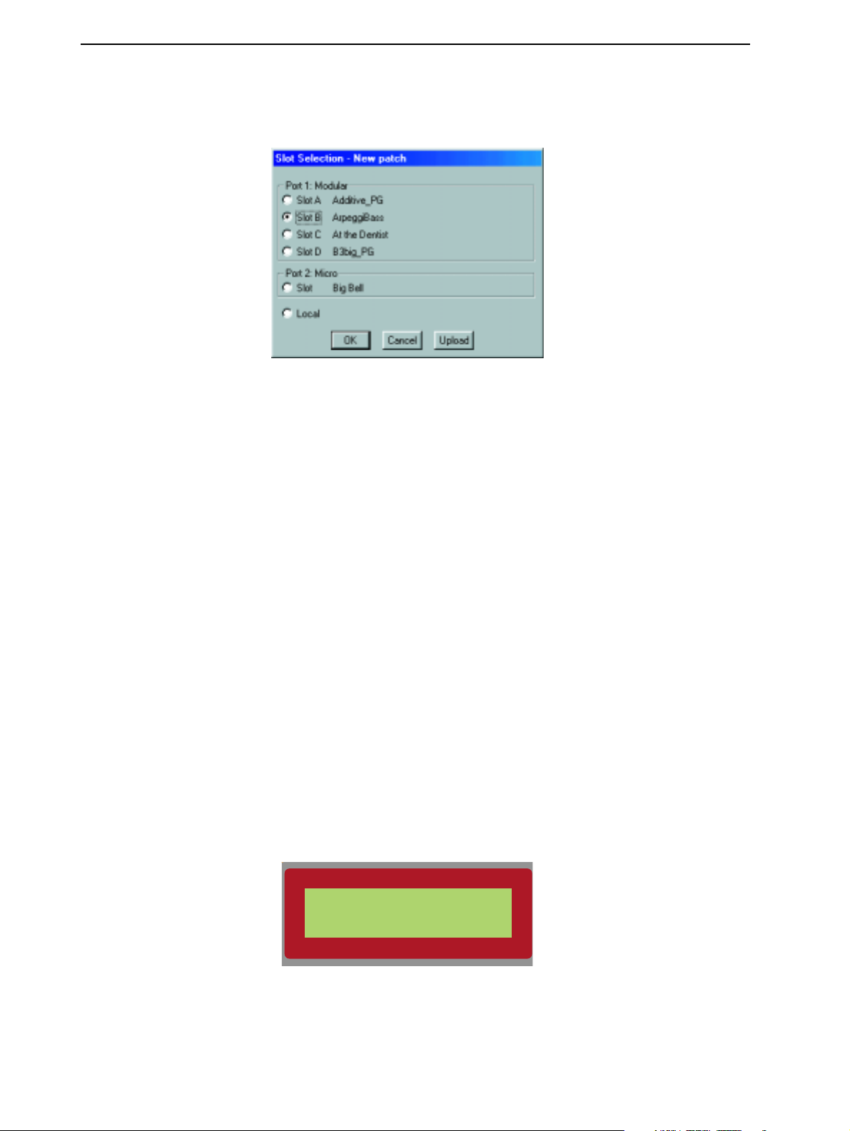
4. Basic functions NORD MODULAR V3.0
selecting Local. This means that you work “off-line”, i.e. you cannot play the patch, only edit. You may
then later download the patch to the synthesizer.
DDDD
OOOOWWWWNNNNLLLLOOOOAAAADDDD
If you selected Local in the example above, you can easily download the Editor patch to the synthesizer
by doing either of the following:
1. right[PC]/Ctrl[Mac]-click on the patch window background and select a slot from the bottom of the
popup. This will download your Editor patch, overwriting the patch that is currently in the destination slot.
2. Select Patch|Download To Slot and select slot in the dialog box that appears.
SSSS
TTTTOOOORRRREEEE
A patch can be stored in two different locations: in the internal memory of the synthesizer, and/or on disk
on the computer. The examples below describes three different ways of saving/storing a patch.
1. Save a patch only on the computer by selecting File|Save. File|Save As will let you rename the patch
2. Store a patch in one of the Nord Modular internal memory locations by pressing the
before saving to disk. File|Save All will save all open Editor patches.
from a PC Editor automatically gets the extension ‘.pch’. For patches saved in a Mac Editor to be
readable in a PC Editor, you must manually type in the extension ‘.pch’ in the file name.
on the front panel once. The
up/down
pressing
Modular.)
AAAA
PPPPAAAATTTTCCCCHHHH
N
S
AAAA
PPPPAAAATTTTCCCCHHHH
AVIGATOR
TORE
again. Abort by pressing any other button. (This example is not valid for Micro
TTTTOOOO
LED
buttons and a memory location (1-99) with the
TTTTHHHHEEEE
SSSSYYYYNNNNTTTTHHHHEEEESSSSIIIIZZZZEEEERRRR
above the
Note! patches that are saved
S
TORE
button will flash. Select a bank (1-9) with the
R
OTARY DIAL
S
TORE
.
Confirm by
button
xxx Patch Name
Store?
3. To store a patch in Nord Modular internal memory from the Editor, select Tools|Browser.
Right[PC]/Ctrl[Mac]-click on a memory location or a bank in the Synth tab and select ‘Save Slot X
Page 22
Page 31

NORD MODULAR V3.0 4. Basic functions
To:...’.
new patch. Make sure you do not overwrite patches you want to keep!
There is a memory protect function to minimize the risk of accidentally overwriting patches (not in Micro Modular). Read more about the internal memory protection in the section “Memory Protect” on
page 56.
AAAA
BBBBOOOOUUUUTTTT
As mentioned above, the Nord Modular internal memory is divided into 9 banks with 99 memory locations each. However, it may not be possible to fit in 891 (9x99) patches at the same time in the Nord
Modular memory due to the total size of the patches.
The dynamic structure of the internal memory makes it suitable to consider it a storage device similar to
a computer hard disk, with banks representing folders and patches representing files.
When you want to store a patch in a memory locations that don’t contain any patches are indicated in
the
Note that the original patch in the selected memory location will be overwritten by your
N
D
ISPLAY
N
TTTTHHHHEEEE
N N
as shown below:.
OOOORRRRDDDD
M
M
OOOODDDDUUUULLLLAAAARRRR
M M
IIIINNNNTTTTEEEERRRRNNNNAAAALLLL
MMMMEEEEMMMMOOOORRRRYYYY
xxx Unused
Store?
If you should run out of internal memory when trying to store a patch, this will be indicated by the fol-
D
lowing message in the
ISPLAY
:.
Patch Name
Memory Full
You will then have to delete one or several patches to make room for new ones. This can be done using
the Patch Browser tool. See “Browser” on page 77 for more info.
AAAA
DDDDDDDD
MMMMOOOODDDDUUUULLLLEEEESSSS
The modules are grouped together in module groups. You access these groups by clicking the tabs in the
toolbar located above the patch window. The various modules in each group are distinguished by icons.
TTTTOOOO
AAAA
PPPPAAAATTTTCCCCHHHH
Select a group tab, click-hold on a module icon and drag it to the patch window. When you place the
cursor over any of the module buttons, a brief description of the module appears together with information of the amount of patch Load (Sound engine power) it will use (PC version only).
Page 23
Page 32

4. Basic functions NORD MODULAR V3.0
Drag the “phantom frame” of the selected module to the patch window. The other modules will move,
if necessary, when you drop a new one. The modules will automatically snap to a grid in the patch window. The patch window will expand when needed and scroll-bars will appear at the bottom and to the
right if the patch window becomes larger than the available screen space. As you add modules to the patch
window, the patch Load indicators on the toolbar will expand, indicating the total use of the Sound en-
gines. Maximum Σ patch Load is 100%. See more in “Patch and voice allocation” on page 211.
Another way of adding modules to the patch is by right[PC]/Ctrl[Mac]-clicking on the background of
the patch window. A popup of the module groups appears. Select desired module by selecting it from the
popup. The cursor gets a plus sign next to it. Place the cursor where you want the module to be placed
and click to drop the module.
RRRR
EEEENNNNAAAAMMMMEEEE
AAAA
MMMMOOOODDDDUUUULLLLEEEE
Double-clicking on the name of the module lets you rename the module. You can also right[PC]/
Ctrl[Mac]-click on the gray background of the module and select Rename.
MMMM
OOOOVVVVEEEE
AAAA
MMMMOOOODDDDUUUULLLLEEEE
You can move the modules in the patch window by click-holding on its gray “panel” and move the frame
that appears. Any connected cables will extend themselves and other modules will move out of the way
automatically. You can also move several modules at the same time by placing the cursor on the patch
window background and click-hold and mark the modules you want to move. Another way of selecting
several modules is to Ctrl[PC]/Shift[Mac]-click on the desired modules. The names of the selected modules are highlighted to indicate that they have been selected.
DDDD
EEEELLLLEEEETTTTEEEE
AAAA
MMMMOOOODDDDUUUULLLLEEEE
To delete a module from a patch, either click on the module and press Delete on the computer keyboard
or select Clear from the Edit menu. Alternatively, right[PC]/Ctrl[Mac]-click on a module’s background
and select Delete from the popup. Note that all cable connections made to the module will also be deleted. You can also delete several modules by selecting them as described in the example above. Then, either
press the Delete key, select Clear from the Edit menu or right[PC]/Ctrl[Mac]-click on one of the selected
modules and choose Delete from the popup.
Page 24
Page 33

NORD MODULAR V3.0 4. Basic functions
PPPP
AAAATTTTCCCCHHHH
IIII
NNNNPPPPUUUUTTTTSSSS
CCCCOOOONNNNNNNNEEEECCCCTTTTIIIIOOOONNNNSSSS
AAAANNNNDDDD
OOOOUUUUTTTTPPPPUUUUTTTTSSSS
There are two types of main connectors on the modules in the Nord Modular Editor: inputs and outputs.
The inputs have circular, and the outputs have square connectors.
CCCCOOOONNNNNNNNEEEECCCCTTTTOOOORRRR
TTTTYYYYPPPPEEEESSSS
There are four different types of connectors that are used for different signals. These connectors are distinguished by different colors:
• audio signal connectors: Red (96 kHz sampling frequency)
• control signal connectors: Blue (24 kHz sampling frequency)
• logic signal connectors. Yellow (24 kHz sampling frequency)
• slave signal connectors: Gray (24 kHz sampling frequency)
CCCC
OOOONNNNNNNNEEEECCCCTTTTIIIINNNNGGGG
CCCCAAAABBBBLLLLEEEESSSS
IIIINNNN
AAAA
PPPPAAAATTTTCCCCHHHH
Place the cursor on a module connector and click-hold. The cursor will change to a plug.
Drag the cursor to a suitable connection elsewhere in the patch. As you drag the cursor away from the
source connector, a line will appear between the cursor and the connector. When you reach the destination connector, the cursor will change to a cable with a white dot instead of a plug. As you release the
mouse button, a cable will appear between the two connections. The color of the output connection will
determine the color of the resulting cable. You can later change the cable color if you like.
It is also possible to connect cables between connectors of different colors, e.g. connect an audio signal
output to a control signal input etc. This depends on the actual application. If a connection is not possible
to make, this will be shown; the cursor will not change to a cable with a dot as you reach the “illegal”
destination connector. It is not possible to damage the system in any way by connecting “wrong” - feel
free to experiment!
You can connect one output to several inputs to make a branch connection.
Page 25
Page 34

4. Basic functions NORD MODULAR V3.0
You can also make a serial connection, from input to input, provided that the first input in the chain is
connected to an output. The result is exactly the same as in a branch connection. If a module within a
serial cable chain is removed, the remains of the cable chain will be re-routed.
It is also possible to make a serial connection between several inputs, without connecting to an output.
This won’t result in any signal flow, but can be useful if you want to choose an output after having connected all inputs. These “non-functional” input-to-input connections are indicated by white cable color.
When you connect such a chain to an output, the cable color will change to the output’s color. It is also
possible to combine branch and serial connections in several ways. For example, you could have a serial
connection branch off anywhere in the chain.
HHHH
IIIIGGGGHHHHLLLLIIIIGGGGHHHHTTTT
CCCCAAAABBBBLLLLEEEESSSS
AAAANNNNDDDD
CCCCAAAABBBBLLLLEEEE
CCCCHHHHAAAAIIIINNNNSSSS
To make it easy to follow cable connections and signal paths visually in the patch, click-holding a connector will highlight any connected cables or cable chains.
DDDD
IIIISSSSCCCCOOOONNNNNNNNEEEECCCCTTTT
OOOORRRR
RRRREEEE
----
RRRROOOOUUUUTTTTEEEE
CCCCAAAABBBBLLLLEEEESSSS
IIIINNNN
AAAA
PPPPAAAATTTTCCCCHHHH
To remove a cable, right[PC]/Ctrl[Mac]-click on a connection (input or output) and select Disconnect,
or double-click-hold or Ctrl[PC]/Alt[Mac]-click (left mouse button) on a connection (an extra wire appears next to the connector cursor) and “pull out” the connector by dragging the connector symbol away
from the input/output and release the mouse button.
right[PC]/Ctrl[Mac]-click OR Double-click or
Ctrl[PC]/Alt[Mac]-click
If you place the “disconnected” plug on another connection instead, the cable will be rerouted.
Page 26
Page 35

NORD MODULAR V3.0 4. Basic functions
EEEE
DDDDIIIITTTT
PPPPAAAARRRRAAAAMMMMEEEETTTTEEEERRRRSSSS
FFFF
OOOOCCCCUUUUSSSS
IIIINNNN
AAAA
PPPPAAAATTTTCCCCHHHH
A parameter can be a knob¨, slider or a selector switch (button). Put a parameter “in focus” by clicking
on it. An increment and decrement button appears below the knob or slider parameter as you move the
cursor over it, and the current setting of the parameter displays briefly in a yellow hintbox. When you
click on the parameter, the increment/decrement buttons (or button selectors) are highlighted. Note that
to be able to put a parameter in focus, the patch has to be active in the synthesizer.
If Nord Modular (not Micro Modular) is in Edit mode (by pressing the
D
also be active in the Nord Modular
the focus with the left and right
ISPLAY
N
AVIGATOR
, and you can adjust it with the
buttons, or with the left and right arrow buttons on the
computer keyboard, or by clicking with the mouse. The left and right
E
DIT
button), the parameter will
R
OTARY DIAL
N
AVIGATOR
and arrow buttons
.
You move
will only scroll through the parameters of one module.
S
To move the focus to another module in the patch, press and hold
N
between the modules with the up/down/left/right
AVIGATOR
HIFT
on Nord Modular, then jump
buttons. The Ctrl[PC]/Alt[Mac] key on
the computer keyboard together with the arrow buttons have the same function. Note that you have to
N
use the up/down arrow or up/down
AVIGATOR
buttons to jump between modules that are placed
above/below each other in the patch window.
N
By the pressing the up/down
AVIGATOR
buttons or the up/down arrow buttons on the computer keyboard, you can move the focus between the Morph group in the toolbar, the first module in the Poly
Voice Area and the first module in the Common Voice Area.
EEEE
DDDDIIIITTTTIIIINNNNGGGG
You can edit the parameters with the mouse. Place the cursor over a knob, click-hold it (put it in focus)
and then move the mouse. The knobs have no end stops; you may jump from maximum to minimum
by turning past the 6 o’clock position (if Knob control is set to ‘Circular’ in the Setup|Options dialog
box). When a knob is in focus, two small buttons will appear beneath the knob. Clicking on the ‘up’ button will increase the value for each click and clicking the ‘down’ button will decrease. You can also use
the computer keyboard + and - keys to increase and decrease the focused parameter value. Click on a selector switch to select e.g. a waveform of an oscillator. The selected button will be “depressed”. If Nord
E
Modular (not Micro Modular) is in Edit mode (by pressing the
D
will also be active in the Nord Modular
Editing a knob Editing a button
ISPLAY
, and you can edit it with the
DIT
button), the highlighted parameter
R
OTARY DIAL
.
Page 27
Page 36

4. Basic functions NORD MODULAR V3.0
SSSS
IIIIGGGGNNNNAAAALLLLSSSS
DDDD
EEEEFFFFIIIINNNNIIIITTTTIIIIOOOONNNNSSSS
Just as in a traditional analog system, modules and parameters in Nord Modular interact with each other
by means of signals being patched from one place to another. In a typical analog system, these signals are
represented by voltage ranging from e.g. -10 to +10 volts. The signal levels in the Nord Modular system
are represented by “units”. These units have nothing to do with the internal resolution of the Nord Modular system which is 24-bit, but is used to more easily indicate levels in the system. Nord Modular uses
four types of signals in its patches:
• bipolar audio signals (-64 to +64 units)
• bipolar and unipolar control signals (-64 to +64 units, 0 to +64 units or 0 to -64 units)
• logic (high or low) control signals (0 or +64 units)
• slave module control signals (fix the coarse pitch between master and slave modules)
The illustration below shows the levels and the polarity of the signals from the keyboard, an LFO, an
envelope, an audio signal and a logic signal.
IIIINNNN
TTTTHHHHEEEE
PPPPAAAATTTTCCCCHHHH
Envelope (unipolar) Logic
units
+64
G9
E4
0
C-1
-64
Audio (bipolar) LFO (bipolar)
The LFO is an example of a bipolar modulator. Bipolar means that it sends both positive and negative
levels (peak to peak –64 to +64 units). The keyboard is another example of a bipolar modulator. The key
E4 (MIDI note number 64) represents 0 units in the Nord Modular system.
The ADSR envelope generator is an example of a unipolar modulator. It will only modulate in one direction, either positive or negative. In the case of Nord Modular ADSR envelopes, they range from 0 to
+64 units.
time
Page 28
Page 37

NORD MODULAR V3.0 4. Basic functions
The Clock generator is an example of a module that sends logic signals. A logic signal is also a unipolar
signal but it has only two possible values, two states: low (0 units) or high (+64 units).
The types of output signals of each module in Nord Modular will be described further on in this manual
using the definitions:
RRRR
EEEESSSSOOOOLLLLUUUUTTTTIIIIOOOONNNN
The internal resolution of the Nord Modular system is 24 bits. This ensures a supreme audio quality. The
headroom of the audio signals in Nord Modular is -12 dB for every sound source. This means that if you
mix more than 4 sound sources in a voice, at very high or un-attenuated levels, distortion may occur. This
is easily dealt with by attenuating the levels of the sound sources.
The mix bus headroom of the output modules is -6 dB per bus. See the headroom diagram in “Head-
room” on page 215.
The amplitude of the audio signals increases for each voice you play. A monophonic patch with an amplitude that is perfectly within the headroom, might produce distortion in the Output modules if more
voices are added and played together.
To determine where any unwanted distortion occurs, first try to lower the level on the Output module(s)
in the patch. This action removes any mix bus related distortion. If this does not help, check the input
signals to the mixers in the patch for possible distortion
bipolar, unipolar
AAAANNNNDDDD
HHHHEEEEAAAADDDDRRRROOOOOOOOMMMM
and
logic
.
AAAA
UUUUDDDDIIIIOOOO
CCCC
OOOONNNNTTTTRRRROOOOLLLL
LLLL
OOOOGGGGIIIICCCC
SSSSIIIIGGGGNNNNAAAALLLLSSSS
Audio signals are bipolar as described above. The audio signals in Nord Modular are 24-bit at 96 kHz
sampling frequency for extremely high quality, and they have highest priority in the Sound engines. Audio connectors are distinguished by the red color. Do not let the description “audio” stop you from experimenting with these signals. They can be used to modulate things too. You can, for example, patch
the red audio output from an oscillator to a blue Pitch input of another oscillator.
SSSSIIIIGGGGNNNNAAAALLLLSSSS
Control signals are sent from envelope generators, LFOs, the keyboard, sequencers etc. The control signals can be either uni- or bipolar. They are used to control or modulate parameters in a patch. The control
signals are 24-bit at 24 kHz sampling frequency, i.e. a quarter of the audio signal bandwidth. This is because they are often low-frequency signals by nature, and do not require a high bandwidth. The control
signal connectors are distinguished by the blue color.
SSSSIIIIGGGGNNNNAAAALLLLSSSS
Logic signals are used to clock, trig or gate different functions. They have two possible levels, low (0 units)
or high (+64 units). The logic signals use the same bandwidth and resolution in Nord Modular as the
control signals.
Logic signal connectors are distinguished by the yellow color.
The state when a logic signal switches from 0 units to +64 units, is called the positive edge. When the
logic signal change back to 0 units again, is called the negative edge. The logic inputs in the system can
react to an incoming signal in four different ways. These are easily recognized by one of three symbols or
the absence of a symbol, next to the input.
,
,
RRRREEEEDDDD
, ,
,
,
, ,
,
,
YYYYEEEELLLLLLLLOOOOWWWW
, ,
CCCCOOOONNNNNNNNEEEECCCCTTTTOOOORRRRSSSS
BBBBLLLLUUUUEEEE
CCCCOOOONNNNNNNNEEEECCCCTTTTOOOORRRRSSSS
CCCCOOOONNNNNNNNEEEECCCCTTTTOOOORRRRSSSS
Page 29
Page 38

4. Basic functions NORD MODULAR V3.0
A logic input that responds to both edges of the logic signal has no symbol next to it. Please note that
even though they respond to both edges, the response is not the same for the positive and the negative
edge. An example of this is the Gate input on the ADSR envelope generator. This input ”starts” the envelope when the positive edge of a logic signal appears and “releases” the envelope when the logic signal
switches back to 0 units again.
A logic input that reacts only to the positive edge has an arrow, pointing upwards, next to it. This is a
typical behaviour of a clock input on a sequencer module or a clock divider. This input is only interested
in the positive edges of a logic signal.
There are some logic inputs that will react to the positive edge of a logic signal only if there is a clock
signal coming in to the module as well. These inputs have an arrow, pointing upwards towards a horizontal marker, next to them. The Rst input on the various sequencer modules is an example of this. These
modules will reset in sync with the next clock signal (on the Clk input) when they receive a positive edge
at the Rst input.
The logic Clock input on the Clock divider module is an example of an input that reacts the same way
to both of the edges of an incoming logic signal. This input has a double-sided arrow next to it.
The different behaviors of the logic inputs are important to remember. It is possible to patch other signals
than logic ones to the logic inputs. The output of a LFO, for instance, can be a good clock source or could
be used to start envelopes. The logic input will not mind having a control or an audio signal connected
to it. The logic inputs interpret any signal with a level of 0 units or less as a low signal and any signal with
a level greater than 0 units as a high signal.
Page 30
Page 39

NORD MODULAR V3.0 4. Basic functions
SSSS
LLLLAAAAVVVVEEEE
SSSSIIIIGGGGNNNNAAAALLLLSSSS
There are two types of oscillator and LFO modules in Nord Modular, masters and slaves. These two types
of modules are equipped with gray connectors. A slave module must be connected to a master module to
receive a frequency reference (the coarse pitch). In practice this means that the slave will follow the master
as the frequency changes. A slave module can, however, act on its own without having to be connected
to a master. In these cases the slave module transmits a steady frequency.
This signal is not particularly suited to connect to anything else in Nord Modular except another gray
connector. The outputs are labelled “Slv” and the inputs are labelled “Mst”.
TTTT
HHHHEEEE
MMMMAAAASSSSTTTTEEEERRRR
The concept of the master and slave modules is to help you reduce the load on the Sound engines. A slave
module requires less Sound engine power, allowing for more modules in the patch, or more voices. They
can also make your work a lot easier when building a multi-oscillator patch with one master oscillator and
a couple of slaves. If you need to change the over-all tuning of the sound, this can be done for all the
oscillators by just changing the master oscillator.
AAAANNNNDDDD
,
,
GGGGRRRRAAAAYYYY
, ,
SSSSLLLLAAAAVVVVEEEE
CCCCOOOONNNNNNNNEEEECCCCTTTTOOOORRRRSSSS
CCCCOOOONNNNCCCCEEEEPPPPTTTT
BBBB
AAAANNNNDDDDWWWWIIIIDDDDTTTTHHHH
The two different bandwidths of the signals in Nord Modular are important to keep in mind. You can
patch a red audio output to a blue control input and vice versa but sometimes the results might be surprising. Some of the LFOs are capable of producing audible frequencies. Since the output of an LFO is
a control signal, updated at the quarter-speed of an audio signal, the quality of an LFO generated signal
might not be good enough to be used as an audio signal. If high audio quality is important in a patch,
use oscillators as audio signal generators instead. The LFOs can, however, provide excellent signals to be
used as a frequency modulators in an FM-type patch. Another example could be the Control Mixer,
which could be used to mix audio signals, but with a lower sound quality.
EEEE
XXXXPPPPEEEERRRRIIIIMMMMEEEENNNNTTTT
You can always try to patch the three different types of signals to wherever you want. You may run into
situations where the result of a connection will not be what you expected, but that is part of the beauty
with a modular system like this. A blue control signal output can be very useful modulating on a yellow
logic signal input, and an audio signal output can certainly produce interesting results connected to a control signal input. The colors are only there to help you identify the various signal types, not to restrict any
experiments.
CCCCOOOONNNNSSSSIIIIDDDDEEEERRRRAAAATTTTIIIIOOOONNNNSSSS
Page 31
Page 40

4. Basic functions NORD MODULAR V3.0
MMMM
OOOODDDDUUUULLLLAAAATTTTIIIIOOOONNNN
The method of controlling one function in a module with another function is called to “modulate”.
When you play on a keyboard and the oscillator changes its pitch, you are modulating the pitch with the
keyboard signal. Another example is an envelope opening up a filter when a key is pressed. Logic signals
from the keys tell the envelope to start modulating the cut-off frequency of the filter. Modulation can be
positive or negative, e.g. the cut-off frequency of a filter can increase with positive modulation and decrease with negative modulation.
As you will see, there are some modules in Nord Modular that can change the polarity of a modulator
signal. Some modules can be set to send either bipolar or unipolar control signals, like the Constant module or the Control Sequencer module.
MMMM
OOOODDDDUUUULLLLAAAATTTTIIIIOOOONNNN
A module parameter that can be modulated from an external source has a modulation input, often in
combination with modulation amount control. This is called a mod-input. The modulation amount control attenuates the incoming signal. The mod-inputs can be red, as in the OscillatorA module, which
means it is capable of handling signals at full audio bandwidth, or they can be blue, as in the FilterF module, working at 1/4 audio bandwidth.
MMMM
----
OOOODDDD
AAAAMMMMOOOOUUUUNNNNTTTT
There are three different response behaviors of the mod-amount knobs next to the modulation inputs:
linear [Type I], exponential [Type II] and amplified linear [Type III]. The different response type(s) will
be indicated for each module in the module reference section starting on page 93.
IIIINNNNPPPPUUUUTTTTSSSS
KKKKNNNNOOOOBBBBSSSS
(
(
AAAATTTTTTTTEEEENNNNUUUUAAAATTTTOOOORRRRSSSS
( (
))))
[T
[T
I]
I]
YYYYPPPPEEEE
[T[T
I] I]
The mod-amount knobs attenuates the incoming signal in a linear fashion. A setting of 127 (maximum)
leaves the incoming signal unaffected, a setting of 64 attenuates the incoming signal by a factor 0.5 (leaving half of the level of the incoming signal to modulate). A setting of 0 shuts off the modulation completely. The pulse width in the aforementioned scenarios is an example of Type I attenuation.
[T
[T
II]
II]
YYYYPPPPEEEE
[T[T
II] II]
The mod-amount knob attenuates the incoming signal in an exponential fashion. A setting of 127 (maximum) leaves the incoming signal unaffected, a setting of 64 attenuates the incoming signal by a factor
considerably less than 0.5 (leaving less than half of the level of the incoming signal to modulate). A setting
of 0 shuts off the modulation completely. The pitch mod-input on the various oscillators are examples of
Type II attenuation.
Page 32
Page 41

NORD MODULAR V3.0 4. Basic functions
[T
[T
III]
III]
YYYYPPPPEEEE
[T[T
III] III]
The mod-amount knob affects the incoming signal in an attenuated and amplified, linear fashion. A setting of 127 (maximum) amplifies the incoming signal to twice its original level, a setting of 64 leaves the
incoming signal unaffected and a setting of 32 attenuates the incoming signal by a factor of 0.5 (leaving
half of the level of the incoming signal to modulate). A setting of 0 shuts off the modulation completely.
The frequency mod-input on the various filters are the sole examples of Type III attenuation.
Signal attenuation/
amplification
2.0
TYPE III
1.5
1.0
TYPE I
0.5
TYPE II
0
0 20 40 60 80 100 120
Mod-amount setting
MMMM
OOOODDDDUUUULLLLAAAATTTTIIIIOOOONNNN
PPPP
UUUULLLLSSSSEEEE
WWWWIIIIDDDDTTTTHHHH
EEEEXXXXAAAAMMMMPPPPLLLLEEEESSSS
MMMMOOOODDDDUUUULLLLAAAATTTTIIIIOOOONNNN
Let us use the pulse width on the OscillatorA module as an example in two scenarios:
Page 33
Page 42

4. Basic functions NORD MODULAR V3.0
1. If you want to modulate the pulse width from the minimum value (1%) to the maximum value
(99%) with a positive envelope (that produces a control signal with a peak to peak level swing from 0
units to +64 units), set the initial pulse width to 1% and the mod-amount to 127.
2. If you want to modulate the pulse width from the minimum value (1%) to the maximum value
(99%) with an LFO (that produces a bipolar control signal with a peak to peak level swing from –64
units to +64 units), set the initial pulse width to 50% and the mod-amount to 64.
Increasing the setting of the mod-amount can not push the pulse-width beyond the limits (1% –
99%), but it will make the modulation signal reach the maximum/minimum pulse-width earlier. A
mod-amount setting of 127 would result in maximum pulse-width modulation at a control signal of
+/– 32 units.
Note the difference between the total amount of modulation from an envelope (unipolar, 64 units) and
from an LFO (bipolar, -64 to + 64 units = 128 units). This explains why the first scenario has the modamount set to 127, and the second scenario set to 64 for maximum modulation.
PPPP
A signal routed to a Pitch input on a module affects the pitch by modulating it linearly in the
IIIITTTTCCCCHHHH
MMMMOOOODDDDUUUULLLLAAAATTTTIIIIOOOONNNN
note
scale
(see figure below). The figure shows an A4 note being pitch modulated by a symmetric bipolar signal.
amplitude
A3, 220 Hz
A5, 880 Hz
pitch
A4, 440 Hz
Page 34
Page 43

NORD MODULAR V3.0 4. Basic functions
FFFF
RRRREEEEQQQQUUUUEEEENNNNCCCCYYYY
A signal routed to an FM input on a module affects the pitch by modulating it linearly in the
MMMMOOOODDDDUUUULLLLAAAATTTTIIIIOOOONNNN
(FM)
(FM)
(FM) (FM)
frequency
scale (see figure below). The figure shows an A4 note being pitch modulated by a symmetric bipolar signal.
amplitude
140 Hz
740 Hz
pitch
A4, 440Hz
As you can see, FM modulation results in equal pitch shifting, in Herz, on either side of the basic pitch,
whereas Pitch shifting results in equal shifting in the note scale.
SSSS
YYYYNNNNCCCC
A waveform of an oscillator with a Sync input can be synchronized with a wave of another oscillator. The
synchronization forces the wave to restart each time the modulating wave raises above 0. This results in
a complex waveform that depends both on its own pitch and on the modulator pitch. When sync is used,
the oscillator pitch is locked to the modulator pitch. If you change the modulator pitch, you will affect
Page 35
Page 44

4. Basic functions NORD MODULAR V3.0
the overall pitch, and if you change the oscillator pitch, this will create changes in timbre rather than in
pitch.
amplitude
Modulator wave
amplitude
Synchronized
oscillator wave
If you let the synchronized oscillator pitch vary continuously, from an LFO or other modulator, you will
change the timbre of the wave in a very interesting and characteristic way.
MMMM
AAAAXXXXIIIIMMMMUUUUMMMM
The maximum amount of modulation that a module (with one exception) can accept is +/–64 units from
the initial setting of the parameter. The exception to this behaviour are all the Filter frequencies with a
mod-input. These can accept +/–128 units of modulation. The modulation amount is the sum of all
modulation appearing at the modulation inputs.
MMMMOOOODDDDUUUULLLLAAAATTTTIIIIOOOONNNN
time
time
Let us use the Master Oscillator module as an example: there are two pitch modulation inputs and the
KBT function (see “The KBT parameter” on page 45). The total modulation amount of these three in-
puts can not be greater than +/–64 semitones. If you turn the coarse tuning down to e.g. E0, add a transpose value of +64 with a Constant module to the first pitch-mod input, you will reach a point, when
playing on the keyboard, where the pitch of the oscillator will be fixed. Any additional, positive modulation will have no effect, which could lead to interesting effects. For example, an LFO would be able to
modulate the pitch of the oscillator downwards, but not upwards.
Page 36
Page 45

NORD MODULAR V3.0 4. Basic functions
KKKK
NNNNOOOOBBBBSSSS
The 18
sources for modulation. Also control- and on/off pedals can be used for modulation (not on Micro Modular). The
also become an important part of the patch itself, controlling, for example, a mod-amount in real time,
or affecting the entire path of a signal by controlling a switch module or a mixer.
AAAA
SSSSSSSSIIIIGGGGNNNN
A parameter can be either a continuous parameter (knob), or a selector switch (button). There are two
ways of assigning and deassigning a
1. right[PC]/Ctrl[Mac]-click on a parameter in the Editor window, select Knob from the popup menu
AAAANNNNDDDD
K
NOBS
K
AAAA
and select one of the Knobs in the menu.
CCCCOOOONNNNTTTTRRRROOOOLLLLLLLLEEEERRRRSSSS
on the front panel of Nord Modular (3
NOBS
and controllers can be assigned to almost any parameter in Nord Modular. They can
KKKKNNNNOOOOBBBB
TTTTOOOO
AAAA
PPPPAAAARRRRAAAAMMMMEEEETTTTEEEERRRR
K
NOB
to a parameter.
K
NOBS
+ 1 button on Micro Modular) are useful
K
To deassign a
by selecting another (unused) Knob in the popup menu. This method also allows you to assign the
other available, external controllers (Pedal, After touch and the On/Off switch) to a parameter. These
controllers are found at the bottom of the Knob popup.
2. (Not Micro Modular) Put a parameter in the Editor window in focus, press the
front panel, press and hold the
light up, indicating an assignment. To deassign a
K
NOB
A
range as well, use a Morph group instead. The Morph concept is described in “Morph groups” on
page 40.
or a controller will always control the entire range of a parameter. If you need to control the
NOB
, select Disable at the bottom of the popup menu. You can also re-assign a
E
DIT
A
SSIGN
button and turn a
K
NOB
K
NOB
. The LED next to the
, press the
S
HIFT
button and turn the
button on the
K
NOB
K
NOB
will
K
NOB
Page 37
Page 46

4. Basic functions NORD MODULAR V3.0
TTTT
K
K
HHHHEEEE
K K
The Knob Floater window is a graphical representation of the
The Knob Floater gives you both visual indication and the possibility to edit the parameters currently
assigned to a
eter, and the name of the module and parameter is shown above the knob. When you edit a knob in the
Knob Floater window, by click-holding and turning the knob, the corresponding module parameter in
the patch window will be focused and change too. If you turn an assigned
front panel, the knob in the Knob Floater and the corresponding module parameter will change, also visually. At the bottom of the Knob Floater, any Control pedal, Velocity and On/Off Switch assignments
are shown. These three parameters can’t be edited from the Knob Floater, only viewed.
Bring up the Knob Floater by selecting Knob Floater from the Tools menu.
NNNNOOOOBBBB
F
F
LLLLOOOOAAAATTTTEEEERRRR
F F
K
NOBS
of the Nord Modular front panel.
K
NOB
. A lit LED next to each knob indicates that the knob is assigned to a module param-
K
NOB
on the Nord Modular
This is a floating window, meaning it can be positioned anywhere in the patch window.
The Knob Floater only shows the assignment for the current patch. It does not indicate assignment in a
Panel Split situation.
Page 38
Page 47

NORD MODULAR V3.0 4. Basic functions
MMMMID
IDI
I
CCCCOOOONNNNTTTTRRRROOOOLLLLLLLLEEEERRRRSSSS
IDID
I I
Almost any parameter in the different modules can be assigned to a MIDI Controller. This is very useful
if you want to record filter frequency adjustments to an external sequencer or if you want to control ex-
K
ternal devices from the
transmit MIDI data when being edited, as well as receive data from external MIDI sources (sequencer,
master keyboard, etc.).
right[PC]/Ctrl[Mac]-click on a parameter and select MIDI controller from the parameter popup. Here
you can choose either to assign the parameter to one four pre-defined controllers or to assign to another
controller by selecting Other.
NOBS
. When a parameter is assigned to a MIDI controller, the parameter will
Choose Other and pick a MIDI controller from the list that appears.
Some of the MIDI Controllers usually have designated functions, like Controller 1, Mod Wheel. These
designated Controllers are just numbers to Nord Modular. You are free to assign up to 119 MIDI Controllers to module parameters. MIDI Controller #32 (Bank Change) and #64 (Sustain Pedal) cannot be
selected from this list. If you want to control external MIDI devices, these labels may have greater importance.
Page 39
Page 48

4. Basic functions NORD MODULAR V3.0
When you edit a parameter that is assigned to a MIDI controller, it will transmit MIDI controller data.
R
It does not matter if you edit the parameter from the Editor or on the synthesizer with the
(not Micro Modular).
OTARY DIAL
You may also assign a parameter to a
K
NOB
as described earlier. In that a case, turning a
K
NOB
in editing the parameter, which subsequently generates MIDI controller data. De-assign a parameter
from a MIDI controller by highlighting a controller and clicking No controller in the dialog box.
K
UUUU
SSSSIIIINNNNGGGG
TTTTHHHHEEEE
K
K K
If you want to use one or several
you will need to take a detour and assign the
NNNNOOOOBBBBSSSS
AAAASSSS
MIDI
MIDI
MIDI MIDI
K
NOBS
CCCCOOOONNNNTTTTRRRROOOOLLLLLLLLEEEERRRRSSSS
to exclusively transmit MIDI controller data to external devices,
K
NOBS
to parameters on modules that are not used (connected) in the patch. Then assign the parameters to MIDI controllers. Very useful for this purpose is the
Constant module (see page 168), which does not use any Sound engine resources. You determine which
MIDI channel to use in the Synth Settings menu. Read more about MIDI channels in “MIDI channels”
on page 55 and page 70.
MMMM
OOOORRRRPPPPHHHH
GGGGRRRROOOOUUUUPPPPSSSS
The Morph groups concept of Nord Modular is a very powerful feature. To put it simple: the Morph
groups lets you simultaneously control defined ranges of up to 25 parameters in a patch, using only one
K
control source (a
NOB
and/or a MIDI controller, for example). As you have figured out, this lets you
produce radical changes in a sound in a very fast and easy way.
The Morph groups and their corresponding knobs are located in the Editor toolbar. There are four
Morph groups available in each patch and you may assign up to 25 different parameters, distributed as
you wish among the four Morph groups. Each Morph group has its own color, making it very easy to see
what parameters are assigned to which Morph group.
will result
Here is an example on how to assign a parameter to a Morph group:
1. right[PC]/Ctrl[Mac]-click on a module parameter (knob or a selector) you wish to control with a
Morph group. Almost any module parameter in Nord Modular can be morphed. Select Morph and
one of the four Morph groups from the menu. The color of the selected knob will now change to the
selected Morph group’s color. Alternatively, first click on any of the Morph group knobs in the tool-
Page 40
Page 49

NORD MODULAR V3.0 4. Basic functions
bar to select it (the blue frame moves to the selected Morph group). Then double-click on the module parameter you wish to assign to the selected Morph group.
2. Every parameter assigned to a Morph group should also be given a Morph range. Click and hold the
Ctrl[PC]/Alt[Mac] key on the computer keyboard and place the cursor on the knob that you
assigned to the Morph group. Click-drag the cursor as if you were turning the knob. A colored sector
will appear, indicating the Morph range. The range will also appear in a yellow hintbox above the
parameter. You can also double-click-hold on a parameter that is assigned to a Morph group to set
the range.
If you assign a selector switch (button) to a Morph group, the Morph range will be set by holding
down the Ctrl[PC]/Alt[Mac] key and clicking on the button in the selector that should be the “last”
(end limit) to be controlled by the Morph.
3. Turning the Morph group knob in the toolbar will now control the morphed parameter within the
selected range.
You can assign each Morph group knob to e.g. a
K
NOB
on the front panel, a pedal (not Micro Modular),
an external MIDI controller, or, as an exclusive feature of the Morph group knobs, to MIDI note values
or keyboard velocity. You will find these two options at the bottom of the MIDI controller popup. To
deassign a parameter from a Morph group, right[PC]/Ctrl[Mac]-click on it and select Disable in the
Morph popup.
EEEE
DDDDIIIITTTTIIIINNNNGGGG
TTTTHHHHEEEE
MMMMOOOORRRRPPPPHHHH
RRRRAAAANNNNGGGGEEEE
The Morph range will always start at the current position of a knob, slider or selector. The relationship
between the setting of the parameter and the Morph range will be fixed, even if you move the setting of
the parameter after a Morph range has been set.
Page 41
Page 50

4. Basic functions NORD MODULAR V3.0
You can edit the morph range (the size of the sector) by double-clicking on the parameter or by using the
mouse in conjunction with the Ctrl[PC]/Alt[Mac] key on the computer keyboard. You can also use the
computer keyboard + and - keys in conjunction with the Ctrl[PC]/Alt[Mac] key to increase and decrease
the focused parameter’s Morph range. Another way is to put Nord Modular in Edit mode by pressing the
E
DIT
button (not Micro Modular). Put the morphed parameter in focus and simultaneously press- hold
S
HIFT
the
You can also get a read-out of which Morph group a parameter is assigned to by pressing the F7 function
key on the computer keyboard. Pressing the F5 key displays the Morph ranges (start and end values) of
the assigned (morphed) parameters.
and
A
SSIGN
buttons and set the amount of Morph control with the
R
OTARY DIAL
.
VVVV
OOOOIIIICCCCEEEESSSS
A patch can be set to a polyphony between 1 and 32 voices, as long as there is enough Sound engine power
available. It is not necessary to manually duplicate all the modules and settings for each voice to create a
polyphonic patch, as it would in a traditional modular system. All you have to do is change the requested
polyphony in the toolbar of the Editor, in the Patch|Patch Settings menu or in the Nord Modular synthesizer (not Micro Modular). To be able to make a patch polyphonic at all, you have to create the patch,
or the part of the patch, you want to be polyphonic, in the Poly Voice Area of the patch window (see
"Poly and Common Voice patch sections” below).
The current actual polyphony of a patch is displayed in the display box next to the requested polyphony
box in the toolbar, and in the Nord Modular
P
gine(s), the system assigns the highest possible amount of voices to the patch instead.
,
,
MMMMOOOONNNNOOOO
, ,
ATCH/LOAD
-
-
AAAANNNNDDDD
- -
button). Should your request for polyphony exceed the current capacity of the Sound en-
PPPPOOOOLLLLYYYYPPPPHHHHOOOONNNNIIIICCCC
D
ISPLAY
(not Micro Modular) in Patch mode (press the
Set the requested number of voices by
clicking the left/right buttons. The requested number of voices is shown in the
‘R’ box and the current actual number of
voices is shown in the ‘C’ box.
PPPPAAAATTTTCCCCHHHHEEEESSSS
Page 42
CineMaxxPG
( 4) -- -- --
See the current actual number of voices
allocated to the patch
Page 51

NORD MODULAR V3.0 4. Basic functions
All patches must have a requested number of voices assigned to them (minimum 1 voice). The dynamic
allocation method used by other multitimbral hardware synthesizers is not applicable with Nord Modular.
S
You can adjust the polyphony by selecting a
(not M icro Modular ). This can be useful if you have a couple of patch es load ed to several
to redistribute the polyphony among the patches.
The Nord Modular note recognition system operates according to the “last note” principle. If you run
out of polyphony and continue to play notes, the synthesizer will always add the last note played and remove the first note, with one exception: it will try to keep the lowest note sounding.
See also “Sound engine” on page 211 for more information about the relationship between voices and
Sound engine power.
PPPP
OOOOLLLLYYYY
A Nord Modular patch can consist of two parts: a polyphonic part and a monophonic part. In the Editor,
these two parts are represented by two sections of the patch window, divided by a horizontal bar. The
upper section is called the Poly Voice Area and the lower section the Common Voice Area. In the Poly
Voice Area you place modules that should be duplicated for each voice, e.g. oscillators, envelope generators and filters. In the lower patch window, the Common Voice Area, you can place modules that should
act equally on all voices in the patch, e.g. different types of Audio modules. Modules used in the Common Voice Area will act on the sum of the signals output from the Poly Voice Area, and consequently
will not be duplicated for each voice in the patch. This gives two big advantages:
• A module is able to process whole chords, and not just a single voice, affecting the sound the same way
an external audio processor would.
AAAANNNNDDDD
C
C
OOOOMMMMMMMMOOOONNNN
C C
V
V
V V
OOOOIIIICCCCEEEE
LOT
PPPPAAAATTTTCCCCHHHH
, press the
SSSSEEEECCCCTTTTIIIIOOOONNNNSSSS
S
HIFT
button and turn the
R
OTARY DIAL
S
LOTS
and wish
• In most situations you will be able to free up Sound engine power (Load) so you could increase the
polyphony of the patch.
Cables cannot be connected from modules in one patch section to modules in the other. The only signals
that can be routed from the Poly Voice Area to the Common Voice Area are two separate audio signals.
The routing is one-way only; from the Poly Voice Area to the Common Voice Area.
Page 43
Page 52

4. Basic functions NORD MODULAR V3.0
EEEE
XXXXAAAAMMMMPPPPLLLLEEEE
This example shows a patch where both the Poly and Common Voice Areas are used:
OOOOFFFF
AAAA
PPPPAAAATTTTCCCCHHHH
TTTTHHHHAAAATTTT
UUUUSSSSEEEESSSS
BBBBOOOOTTTTHHHH
TTTTHHHHEEEE
P
P
P P
OOOOLLLLYYYY
AAAANNNNDDDD
C
C
OOOOMMMMMMMMOOOONNNN
C C
V
V
V V
OOOOIIIICCCCEEEE
A
A
A A
RRRREEEEAAAASSSS
The ‘1Output1’ module in the Poly Voice Area is set to route the signal to CVA L, the left output of the
‘PolyAreaIn1’ module in the Common Voice Area. The sum of all voices from the Poly Voice Area is sent
to the Common Voice Area to be processed in the ‘StereoChorus1’ module and output at
O
2
UT
jack of the synthesizer.
A patch in the Poly Voice Area set to 1 requested voice would give the same result as having the patch
only in the Common Voice Area instead.
TTTT
M
M
HHHHEEEE
If you change a patch with 1 requested voice in the Poly Voice Area to be polyphonic, there are a few
things that you need to be aware of. All modules in the Poly Voice Area are independent from each other,
performing their functions on a “voice” level. This provides you with a big advantage in comparison to
almost any other polyphonic synthesizer. If a traditional polyphonic synth had e.g. 4 voices, it has been
common practice to provide the user with only one LFO for all voices together. This is not the case with
Nord Modular. An LFO used in the Poly Voice Area is unique for each single voice in the patch.
M M
OOOONNNNOOOO
PPPPAAAARRRRAAAAMMMMEEEETTTTEEEERRRR
O
UT
1
and
If you want modules in the Poly Voice Area of a polyphonic patch, e.g. one LFO per voice in a 4-voice
patch, to be synchronized and behave like one single LFO, this can be done with the Mono parameter.
Page 44
Page 53

NORD MODULAR V3.0 4. Basic functions
The Mono parameter makes sure that certain functions in a polyphonic patch are “in sync” with the other
voices.
TTTT
KBT
KBT
HHHHEEEE
KBT KBT
KBT is short for KeyBoard Tracking. The KBT parameter controls the frequency step response from a
keyboard to the module (e.g. the master oscillators, some of the master LFOs and some of the filters). In
the oscillator modules, the pitch can track the keyboard, in the LFO modules the keyboard can modulate
the rate of the LFO and in the filter modules, the cut-off frequency can track the keyboard. When the
KBT parameter in these modules is set to Key (the 12 o‘clock position), the keyboard controls the parameter at the rate of one semitone for each key.
Any pitch bend appearing at the MIDI input will be added to the KBT tracking. Read more about scaling
the pitch bend in “Bend range” on page 57. If you, for instance, set up a sequencer patch, with KBT active
on the oscillators, you can transpose the sequence in realtime by pressing keys on the Nord Modular keyboard. If any filters in a patch have the KBT parameter active, the cut-off frequency will also track the
keyboard.
PPPPAAAARRRRAAAAMMMMEEEETTTTEEEERRRR
Page 45
Page 54

5. Panel reference NORD MODULAR V3.0
5. P
5. P
5. P5. P
AAAAN
NEEEELLLL
NN
R
REEEEFFFFEEEERRRREEEEN
RR
NC
CEEEE
NN
CC
KKKK
NNNNOOOOBBBBSSSS
MMMM
AAAASSSSTTTTEEEERRRR
Adjust the master volume of Nord Modular with this knob. Note that this knob cannot be routed to
MIDI Volume or any other controller. It is separated from the rest of the parameters of the synth. To
affect the volume of a patch from MIDI, you have to assign a controller to any of the Level rotary knobs
of the output modules (see more about these modules on page 96).
PPPP
AAAANNNNEEEELLLL
Pressing the
and D. The A and the B slot will be given six
each.
AAAANNNNDDDD
V
V
V V
S
S
PPPPLLLLIIIITTTT
S S
BBBBUUUUTTTTTTTTOOOONNNNSSSS
OOOOLLLLUUUUMMMMEEEE
P
ANEL SPLIT
OOOOFFFF
button splits the 18
N
N
N N
K
K
NOBS
M
OOOORRRRDDDD
NOBS
M
OOOODDDDUUUULLLLAAAARRRR
M M
in four groups, one for each of the Slots A, B, C
each, the C and D slot will be give three
K
NOBS
K
NOBS
The first six (or three) assigned
different groups (see figure below). For example, a patch in slot C that originally had parameters assigned
K
NOBS
to
temporary for as long as
changed.
Page 46
1-3, will now have them reassigned to
P
ANEL SPLIT
Slot
of the patch in each slot will be rerouted to the
K
NOBS
13-15. The Panel Split knob assignment is only
is active. The original knob assignment in the patch will not be
A
Slot
B
Slot CSlot
D
K
NOBS
of the
Page 55

NORD MODULAR V3.0 5. Panel reference
FFFF
OOOO
/P
/P
IIIINNNNDDDD
When a parameter is assigned to a
and turning the
set the physical position of the
As long as you hold down the
is in Edit mode, the parameter will stay in focus in the
Pressing
all the voices in Nord Modular. Sound sources (oscillators, for example) that are connected directly to an
output module will not be affected by the
CCCCTTTT
You can quickly transpose the Nord Modular keyboard in octave steps with the
total range of the two-octave keyboard can be extended to six octaves. You can transpose the patches in
the four slots individually. This transposition is saved with the other parameters of a patch. The
S
ular is also affected by the
AAAANNNNIIIICCCC
/P/P
K
NOB
, the indicator next to the
K
NOB
will show the parameter in the
K
NOB
to coincide with the actual setting of the parameter in the patch.
F
IND
button, the value of the parameter will not change. If Nord Modular
S
SSSSHHHHIIIIFFFFTTTT
HIFT
buttons are an exclusive feature on the keyboard version only. The MIDI output from Nord Mod-
F
HIFT
IND
+
(
(
KKKKEEEEYYYYBBBBOOOOAAAARRRRDDDD
( (
activates the panic function. This will send an internal MIDI Note Off message to
P
ANIC
VVVVEEEERRRRSSSSIIIIOOOONNNN
O
CT SHIFT
buttons.
D
function.
OOOONNNNLLLLYYYY
ISPLAY
D
ISPLAY
))))
K
NOB
is lit. Pressing and holding
. The arrows that appears will help you to
F
when you release the
O
IND
CT SHIFT
button.
buttons. The
O
F
IND
CT
MIDI
MIDI
MIDI MIDI
MIDI
The
to receive on.
KKKK
NNNNOOOOBBBBSSSS
The 18
time. When a
messages. If you want a
Modular, assign the
TTTTRRRRIIIIGGGG
K
NOBS
LED (
LED (
LED ( LED (
TRIG
K
RRRRAAAACCCCKKKK
LED
indicates incoming MIDI messages on the MIDI channels Nord Modular is set
can be assigned to parameters in a patch. The parameters will then be controllable in real
NOB
is assigned the
K
NOB
K
NOB
VVVVEEEERRRRSSSSIIIIOOOONNNN
K
NOB
to control external MIDI devices, without affecting any parameter in Nord
to a parameter in a “dummy” module (that is not a part of the sound in the
LED
OOOONNNNLLLLYYYY
is l it. The
))))
K
NOBS
can also be set to send MIDI controller
Page 47
Page 56

5. Panel reference NORD MODULAR V3.0
patch) and assign that parameter to the MIDI Controller you wish to transmit. Read more in “MIDI con-
trollers” on page 39.
SSSS
LLLLOOOOTTTT
BBBBUUUUTTTTTTTTOOOONNNNSSSS
Pressing the
S
LOT BUTTONS
A, B, C
and/or D selects the slots for loading, editing or playing. A patch
always has to be loaded into a slot before it can be used. If you select only one slot at a time, the
LED
will indicate this by a flashing green light. The Editor software will follow the slot selection (change
patch window), provided that the patch is uploaded or opened in the Editor.
S
If several slots are selected, by simultaneously pressing several
dicate a selected slot and a flashing LED will indicate the currently active
receive MIDI messages on their set channels, but only the active
To deselect
S
LOTS
all
simultaneously, you can also press an unused
S
LOTS
in a multi-slot setup, press
S
HIFT
and the
S
LOT
buttons, a solid green LED will in-
S
LOT
. Every selected
S
LOT
will transmit MIDI messages.
S
LOT
button (if there are any). However, the un-
)
LOT(S
you want to deselect. To deselect
S
LOT
used Slot will become active.
It is also possible to play several Slots simultaneously (layered) from the keyboard. To do that you must
first change keyboard mode to “Selected Slots” in “Keyboard mode” of the Synth Settings menu. See
“Keyboard mode” on page 54. On the Nord Modular rack model this function works only when playing
S
from the Keyboard Floater in the Editor. To play several
LOTS
layered on the rack model from a master
keyboard, the slots have to be set to the same MIDI channel.
S
LOT
will
SSSS
HHHHIIIIFFFFTTTT
The
Page 48
S
HIFT
button adds secondary functions to other buttons.
Page 57

NORD MODULAR V3.0 5. Panel reference
AAAA
SSSSSSSSIIIIGGGGNNNN
The
K
NOBS
must be in edit mode when you make a
K
NOB
S
HIFT
group). Edit the Morph range with the
/M
/M
OOOORRRRPPPPHHHH
/M/M
A
SSIGN
M
/
ORPH
button allows you to assign a parameter in a patch to be controlled by one of the
. Press and hold assign while the desired parameter is in focus and turn a
K
NOB
assignment. To deselect a
S
while pressing
A
SSIGN
+
allows you to edit the Morph range of the parameter in focus (if it is assigned to a Morph
HIFT
.
R
OTARY DIAL
. See more about Morph in “Morph groups” on
K
NOB
K
NOB
assignment, turn the
. Nord Modular
page 40.
NNNN
AAAAVVVVIIIIGGGGAAAATTTTOOOORRRR
N
AVIGATOR
The
BBBBUUUUTTTTTTTTOOOONNNNSSSS
buttons can be used to select patches and banks or menus and parameters in the menus.
When Nord Modular is in Load mode (Patch/Load LED flashing), you select patches with the left and
right
N
AVIGATOR
buttons, and change banks with the up and down
N
AVIGATOR
buttons. When Nord
Modular is in Edit mode, you select parameters within a module by scrolling with the left and right
IGATOR
buttons, and between the toolbar, PVA and CVA sections with the up and down
buttons. Pressing the
screen as well as in the
S
HIFT
D
N
+
ISPLAY
AVIGATOR
.
buttons sets the focus on different modules in a patch, on
N
AVIGATOR
N
AV
-
RRRR
OOOOTTTTAAAARRRRYYYY
The
D
D
D D
R
OTARY DIAL
while turning the
step of the
GATOR
buttons together with the
IIIIAAAALLLL
is used to enter parameter values. Pressing either the left or right
R
OTARY DIAL
R
OTARY DIAL
N
AVIGATOR
will scroll through the parameters of a module, one parameter for each
. Scroll through the menus in Nord Modular by using the up an down
R
OTARY DIAL
.
Page 49
button
N
AVI
-
Page 58

5. Panel reference NORD MODULAR V3.0
SSSS
TTTTOOOORRRREEEE
There are 9 x 99 patch memory locations and one Synth Settings memory in Nord Modular. The internal
patch memory is divided into 9 Banks, each with 99 memory locations. Generally, there is not enough
room for 9 x99 (891) patches in the internal memory at the same time. The number of patches that can
be stored in the internal memory depends on the patch sizes. Typically, several hundreds of patches fit in
S
the internal memory. The
TORE
button allows you to store patches and Synth Settings.
1. Activate a
P
ATCH/LOAD
the
S
LOT
with a patch by pressing the
button once.
You can not store any patches if Nord Modular is in System or
S
LOT
button. If the
E
DIT
or
S
YSTEM
LED
is lit, press
Edit mode.
2. Press
S
TORE
once. The
S
TORE
LED
will flash.
xxx Patch Name
Store?
N
3. Select a Bank with the up/down
D
IAL
or with the left/right
N
AVIGATOR
AVIGATOR
buttons. Select a memory location with the
S
buttons and confirm by pressing
TORE
one more time.
Pressing any other button will cancel the operation. It is possible to name your patch. The name can
be set in the Patch menu (see “Patch name” on page 57).
The Memory Protect function must be turned Off before storing a patch. If not, the following message
will appear. Read about memory protection (de)activation in “Memory Protect” on page 56.
R
OTARY
Memory protected
If a memory location is occupied by a patch, you will see the name of that patch in the
S
TORE
will overwrite an existing patch.
Page 50
D
ISPLAY
. Pressing
Page 59

NORD MODULAR V3.0 5. Panel reference
If you should run out of internal memory, the following message will be shown:
Patch Name
Memory Full
To make room for more patches, you have to delete some patches from the internal memory. This can
only be done from the Patch Browser in the Editor. See “Synth” on page 78 for details.
SSSS
SSSS
S
S
AAAAVVVVEEEE
Pressing
Modular or in the Editor. This function saves the
loaded to the
S
AVE SYNTH SETTINGS
Settings menus will be described further in “Synth settings in the system menu” on page 52 and page 69.
YYYYSSSSTTTTEEEEMMMM
Press the
Scroll to the desired menu with the
S S
YYYYNNNNTTTTHHHH
S
HIFT
S
S
S
S S
S
TORE
+
S
LOTS
, MIDI channels for the
BBBBUUUUTTTTTTTTOOOONNNN
YSTEM
button below the
EEEETTTTTTTTIIIINNNNGGGGSSSS
will store any settings that you have made in the Synth Settings menus of Nord
S
LOT
selection including the patch locations that were
S
LOTS
will automatically be recalled when you turn on the Nord Modular. The Synth
D
ISPLAY
, to activate the System menu.
N
AVIGATOR
P
ANEL SPLIT
and
buttons and enter a value with the
activation. The settings saved with
R
OTARY DIAL
SYSTEM MENU
<SYNTH> PATCH
.
The System menu is divided in two main parts, Synth and Patch settings.
SSSS
YYYYNNNNTTTTHHHH
The Synth settings are global, affecting the whole instrument.
If you want to keep any changes that you make in Synth settings, they must be stored in the Synth
Settings memory by pressing the S
ular in a multitimbral setup with a sequencer, it can be very useful to store the settings of the MIDI channels etc. in the Synth Settings memory.
PPPP
AAAATTTTCCCCHHHH
The Patch settings affect the patches in the
the patch data when you store the patch in the Nord Modular internal memory or on a computer disk
from the Editor.
HIFT
and the S
S
LOTS
buttons simultaneously.
TORE
individually and are stored together with the rest of
If you use Nord Mod-
Page 51
Page 60

5. Panel reference NORD MODULAR V3.0
SSSS
YYYYNNNNTTTTHHHH
SSSSEEEETTTTTTTTIIIINNNNGGGGSSSS
IIIINNNN
TTTTHHHHEEEE
SSSSYYYYSSSSTTTTEEEEMMMM
MMMMEEEENNNNUUUU
SYSTEM MENU
<SYNTH> PATCH
As mentioned above, the Synth Settings are global. To alert you that you are editing Synth Settings, an
D
S is always shown in the upper right corner of the
N
up/down
data with the
MMMM
AAAASSSSTTTTEEEERRRR
Use this function to tune Nord Modular to other instruments. The range is from +100 to -100 cents. 100
cents is one semitone. Only the tuning of master oscillators are affected by the Master Tune function.
Slave oscillators that are not connected to a master oscillator module will not be affected.
AVIGATOR
R
OTARY DIAL
T
T
UUUUNNNNEEEE
T T
buttons and within the sub menus with the left/right
.
ISPLAY
. Navigate between the sub menus with the
N
AVIGATOR
buttons. Enter
MASTER TUNE S
0 CENT
MIDI
MIDI CCCC
MIDI MIDI
Set the MIDI Clock source and, if the clock source is set to INT (internal), set the tempo.
LLLLOOOOCCCCKKKK
MIDI CLOCK S
(EXT) 120 BPM
If EXT(external) is selected, any incoming MIDI clock can be used as a clock source in a patch. If INT
is activated, the internal clock will be used. Navigate to the tempo indication and set the tempo with the
R
OTARY DIAL
The MIDI clock will be present at the Clock output of the MIDI Global module and at the synthesizer’s
MIDI O
UT
.
port.
Page 52
Page 61

NORD MODULAR V3.0 5. Panel reference
GGGG
LLLLOOOOBBBBAAAALLLL
The MIDI Clock transmits 24 pulses per quarter note. The clock pulses can be divided with this function
and be sent as logic signals at the Sync output of the MIDI Global module (see picture above). These
logic signals can be used to synchronize the internal sequencer modules to an external MIDI sequencer.
SSSS
YYYYNNNNCCCC
GLOBAL SYNC S
4 QUARTER NOTES
A setting of “4 QUARTER NOTES” will result in one logic Sync pulse for every 96 pulses from the
Clock, which is equal to one pulse for every fourth quarter note.
This logic pulse can be used for resetting the sequencer modules in Nord Modular to the “first beat in
the bar”. If you do not use this function, the sequencer modules have no chance of knowing where they
are in a bar. With the Global Sync function activated, it will never take longer than the set number of
quarter notes for the sequencer modules to realign themselves, if you decide to start a MIDI sequence in
the middle of a song.
If you are synchronizing Nord Modular to an external MIDI Clock source, this function will keep track
of any incoming MIDI Song Position Pointer messages.
LLLL
OOOOCCCCAAAALLLL
Turn the MIDI Local Control on or off.
LOCAL S
ON
Select Local On to be able to control Nord Modular from the internal keyboard and the pedals. MIDI
data is also transmitted via the
In the Local Off mode, the keyboard and pedal actions are transmitted only via MIDI and do not control
Nord Modular itself. Local Off should be used with external sequencers as the
Modular is routed back, via the external sequencer, to the
er, double notes will appear when playing the keyboard in Local On mode.
MIDI O
UT
jack.
MIDI I
MIDI O
N
jack. If Echo is active in the sequenc-
UT
jack of Nord
Page 53
Page 62

5. Panel reference NORD MODULAR V3.0
PPPP
RRRROOOOGGGGRRRRAAAAMMMM
CCCCHHHHAAAANNNNGGGGEEEE
In this sub-menu you select how Nord Modular should handle Program Change and Bank Change (Controller #32) MIDI messages. Choose between Off, Send (only), Receive (only) and Send and Receive.
PROGRAM CHANGE S
SEND AND RECEIVE
KKKK
EEEEYYYYBBBBOOOOAAAARRRRDDDD
Here you choose how the Nord Modular keyboard should control the
the keyboard will control only the patch of the active slot, and with Selected Slots activated, all selected
slots are controlled. Use the last function to play several selected
keyboard. On the Nord Modular rack model this function works only when playing from the Keyboard
Floater in the Editor. To play several
have to be set to the same MIDI channel.
MMMMOOOODDDDEEEE
S
LOTS
. With Active Slot selected,
S
LOTS
“layered” on the Nord Modular
S
LOTS
layered on the rack model from a master keyboard, the slots
KEYBOARD MODE S
ACTIVE SLOT
PPPP
EEEEDDDDAAAALLLL
PPPPOOOOLLLLAAAARRRRIIIITTTTYYYY
Some sustain pedals uses inverted polarity to activate the sustain switch. In this menu you can select between the different sustain pedal polarities.
PEDAL POLARITY S
NORMAL
NNNNOOOOBBBB
MMMMOOOODDDDEEEE
K
NOBS
. Immediate means
K
NOB
. Hook means
KKKK
Here you set how Nord Modular should react to changes of the 18 assignable
that the value of the assigned parameter will change immediately as you turn the
that the parameter value will not change until you have turned the Knob past the current parameter value.
KNOB MODE S
IMMEDIATE
Page 54
Page 63

NORD MODULAR V3.0 5. Panel reference
LLLL
EEEEDDDDSSSS
AAAACCCCTTTTIIIIVVVVEEEE
When a patch gets complex, the LEDs of modules like the LFOs or Sequencers could become inaccurate
in the Editor patch window. A lot of blinking LEDs could also slow down the computer. Select NO to
disengage the LEDs in the patch window.
LEDS ACTIVE S
YES
MIDI
MIDI
MIDI MIDI
This function is used to rescale the velocity data received at the
VVVVEEEELLLL
SSSSCCCCAAAALLLLEEEE
MIDI I
N
port.
MIDI VEL SCALE S
( 0) 127
The number to the left is the minimum value and the number to the right is the maximum value. If your
master keyboard transmits maximum velocity as 112, set the maximum value to 112. This ensures that
the velocity response from Nord Modular will properly reflect the velocity transmission of the master keyboard.
MMMMIDI
IDI
CCCCHHHHAAAANNNNNNNNEEEELLLLSSSS
IDI IDI
S
Set the MIDI channel for each
MIDI data.
LOT
(A-D). The set channels will be used for receiving and transmitting
MIDI CHANNELS S
( 1) 2 3 4
If you select ‘--’ the slot will not receive or transmit any MIDI data at all.
SSSS
Here you can name your synth. This is especially useful if you use several Nord Modulars/Micro Modulars with the Editor. The Editor supports up to four Modular synthesizers simultaneously.
YYYYNNNNTTTTHHHH
NNNNAAAAMMMMEEEE
SYNTH NAME S
Select characters with the
buttons.
(C)eline
R
OTARY DIAL
and change the “cursor” position with the left/right
N
AVIGATOR
Page 55
Page 64

5. Panel reference NORD MODULAR V3.0
MMMM
EEEEMMMMOOOORRRRYYYY
Select memory protection ON or OFF for the entire internal patch memory.
P
P
RRRROOOOTTTTEEEECCCCTTTT
P P
MEMORY PROTECT S
OFF
PPPP
AAAATTTTCCCCHHHH
SSSSEEEETTTTTTTTIIIINNNNGGGGSSSS
IIIINNNN
TTTTHHHHEEEE
SSSSYYYYSSSSTTTTEEEEMMMM
MMMMEEEENNNNUUUU
SYSTEM MENU
SYNTH <PATCH>
S
These functions affect the individual patches loaded into the
S
edit by loading it into a
or in the computer together with each patch after having selected
to jump between the four
LOT
. The changes you make in a patch will be stored/saved in Nord Modular
S
LOTS
in any of the sub menus if you wish.)
LOTS
of Nord Modular. Select a patch to
S
TORE
or Save. (Note that it is possible
D
To alert you that you are editing Patch Settings, a P is always shown in the upper right corner of the
PLAY
. Navigate between the sub-menus with the up/down
N
us with the left/right
VVVV
OOOOIIIICCCCEEEESSSS
Set the requested polyphony of the selected patch.
AVIGATOR
buttons. Enter data with the
N
AVIGATOR
R
buttons and within the sub-men-
OTARY DIAL
.
IS
VOICES P
12 CURRENT: 8
Nord Modular will always try to assign as many voices as you request. The current actual number of voic-
D
es assigned is displayed to the bottom right in the
TTTTRRRRLLLL
S
SSSSNNNNAAAAPPPP
selected
CCCC
In this menu you can choose to send a snapshot of the current values of all assigned MIDI Controllers in
the active patch. This is very useful if you are recording in a sequencer program and want to make sure
LOT(S
) (S
SSSSHHHHOOOOTTTT
LOT
LED
lit or flashing). See “Patch and voice allocation” on page 211 for more info.
ISPLAY
. Note that voices will only be assigned to the
-
Page 56
Page 65

NORD MODULAR V3.0 5. Panel reference
the sound sounds exactly as you want. Press the right
snapshot is sent on the MIDI O
of the synthesizer, not on the PC O
UT
N
AVIGATOR
button to send the Controllers.
UT
.
The
CTRL SNAP SHOT P
[--] SEND
VVVV
Here you can select if you want Nord Modular to retrig notes when playing a monophonic patch. In practice this means that if you hold down two keys and release one of them, the other key will automatically
retrig. You can select retrig for the Poly and Common Voice Areas of the patch individually.
OOOOIIIICCCCEEEE
RRRREEEETTTTRRRRIIIIGGGG
VOICE RETRIG P
(POLY:N) COMM:Y
PPPP
With this function you can name a patch.
AAAATTTTCCCCHHHH
NNNNAAAAMMMMEEEE
PATCH NAME P
(M)yBestSound
R
Select characters with the
buttons. The memory locations in Nord Modular are identified by the location number, not the patchname. You can name all your patches “MyBestSound” if you like, as long as you don’t ask us to sort them
out for you later...
EEEENNNNDDDD
RRRRAAAANNNNGGGGEEEE
BBBB
Here you set the range of the incoming pitch bend data in semitones.
OTARY DIAL
and change the “cursor” position with the left/right
N
AVIGATOR
BEND RANGE P
1
The pitch bend data will be added to the control signals from the Note outputs on the Keyboard modules
and to the KBT (keyboard tracking) function. The range is from 0 to 24 semitones if KBT is set to 1.
Oscillators, LFOs and filters using the KBT parameter will be affected by incoming pitch bend data.
Page 57
Page 66

5. Panel reference NORD MODULAR V3.0
KKKK
EEEEYYYYBBBB
RRRRAAAANNNNGGGGEEEE
This function is used to define a keyboard range for a patch. Set the lowest and the highest note to respond to note information.
KEYB RANGE P
( 0) 127
The patch will only receive keyboard information when you play within this range. If you want to use
Nord Modular in a keyboard split situation, select two
to Selected Slots, and set the actual split point with the high key for one of the
for the other one.
VVVV
EEEELLLL
RRRRAAAANNNNGGGGEEEE
With this function you define a velocity range for a patch.
S
LOTS
, make sure that the Keyboard Mode is set
S
LOTS
and the low key
VEL RANGE P
( 0) 127
Set the lowest and highest velocity values. The patch will only sound when it receives velocity within this
range. If you want to use Nord Modular to switch between two or more patches that are set to receive on
S
the same MIDI channel (velocity switching), select two
make sure that the Keyboard Mode is set to Selected Slots, and set the velocity range individually for the
patches.
PPPP
OOOORRRRTTTTAAAAMMMMEEEENNNNTTTTOOOO
Portamento is an effect where the notes slide from one note to the next when you play consecutive notes
on the keyboard. With the Time parameter you set the time it will take to reach the new note.
LOTS
, set them to the same MIDI channel,
PORTAMENTO P
(TIME: 0) NORM
The portamento has two modes: Normal and Auto. In the Normal mode the portamento is always active,
in the Auto mode you activate the portamento by playing legato. This portamento function is available
only if a patch is set to 1 voice, i.e. monophonic. The Portamento function is always active on any keyboard tracking oscillators used in the Common Voice Area, since this is a monophonic area. A portamento Time setting of ‘0’ is the same as portamento ‘off’.
Portamento can also be achieved using the Portamento modules described on page 169. Using the modules, the portamento can be polyphonic as well.
Page 58
Page 67

NORD MODULAR V3.0 5. Panel reference
PPPP
Select if a footswitch connected to the
EEEEDDDDAAAALLLL
MMMMOOOODDDDEEEE
S
USTAIN PEDAL
input on the rear panel should act as a sustain
pedal or as an on/off switch. If you use it as an on/off switch, you have to assign the switch to a module
parameter in a patch.
PEDAL MODE P
SUSTAIN
EEEE
DDDDIIIITTTT
E
With the
parameters of a patch without having the Editor running or the computer connected to your Nord Modular.
DIT
button you put Nord Modular in Edit mode. In this mode you can edit the functions and
D
The module and its parameters will appear in the
ISPLAY
You navigate within a module with the left and right
S
ules in the patch by pressing and holding the
HIFT
button and navigating with all four
and you can edit them with the
N
AVIGATOR
buttons. You can jump to other mod-
R
OTARY DIAL
N
AVIGATOR
tons. Note that the navigation between the modules in a patch depends on how the modules were placed
graphically in the Editor patch window.
N
Press the up and down
AVIGATOR
buttons to jump between the Poly Voice Area, the Common Voice
Area and the Morph group section (in the Editor toolbar). In the upper right corner of the Display is
shown which section you’re currently in: T means Toolbar, P means Poly Voice Area and C means Common Voice Area.
N
The image on the screen, provided that the Editor is connected, will follow the
D
vice versa. If you select a parameter with the mouse, the
ISPLAY
on Nord Modular will echo that selec-
AVIGATOR
buttons and
tion.
PPPP
AAAATTTTCCCCHHHH
Press the
want to load a patch from the internal memory to a
/L
/L
OOOOAAAADDDD
/L/L
P
ATCH/LOAD
button to put Nord Modular in Patch Mode. This button is also used when you
S
LOT
.
.
but-
Page 59
Page 68

5. Panel reference NORD MODULAR V3.0
D
ISPLAY
The
will indicate the name and the number of voices assigned to the current patch.
Patch Name
( 4) -- -- --
S
By pressing
the active
To load a patch into a
1. Select the
2. Press the
HIFT
while turning the
S
LOT
. This is especially useful in multitimbral setups.
S
LOT
, do as follows:
S
LOT
in which you want to load a patch by pressing a
P
ATCH/LOAD
button. The
the patch name will appear in the
R
OTARY DIAL
P
ATCH/LOAD
D
ISPLAY
.
, you can change the number of requested voices of
LED
will flash. A memory location number and
xxx Patch Name
Load?
R
3. Select the desired patch to load with the
S
and load the patch to the
LOT
by pressing the
entire patch banks, you can also use the up/down
If Nord Modular is in Patch Mode (the
matically present the memory locations and patch names in the
OTARY DIAL
P
ATCH/LOAD
or with the left/right
P
ATCH/LOAD
N
AVIGATOR
LED
lit), turning the
S
LOT
button.
N
AVIGATOR
buttons
button again. To switch between
buttons.
R
D
ISPLAY
OTARY DIAL
.
will auto-
Loading a patch will also send a MIDI Bank Change (Controller #32) and Program Change message on
MIDI O
the
You can also load a patch from a memory location to a
UT
port, if the Program Change function is active. (See “Program change” on page 54.)
S
LOT
by sending a MIDI Bank Change and Program Change message to Nord Modular. You have to send on the MIDI channel assigned to the
(See “Program change” on page 54.)
Page 60
S
LOT
.
Page 69

NORD MODULAR V3.0 5. Panel reference
KKKK
NNNNOOOOBBBBSSSS
SSSS
HHHHIIIIFFFFTTTT
The
Modular.
VVVV
OOOOLLLLUUUUMMMMEEEE
Adjust the master volume with the
ume or any other controller. It is separated from the rest of the parameters of the synth. To affect the
volume from MIDI you have to assign a controller to any of the Level rotary knobs of the output modules
(see more about these modules on page 96).
AAAANNNNDDDD
S
HIFT
button is used to access secondary functions of some of the other Knobs and buttons of Micro
BBBBUUUUTTTTTTTTOOOONNNNSSSS
V
OLUME KNOB
OOOOFFFF
M
M
M M
M
IIIICCCCRRRROOOO
. Note that this knob cannot be routed to MIDI Vol-
M
OOOODDDDUUUULLLLAAAARRRR
M M
1/M
1/M
AAAASSSSTTTTEEEERRRR
1/M1/M
The first of the 3
trollable in real time. The
controllers” on page 39. If Shift is pressed, the knob is used to change the master tune (+/- 1 semitone in
steps of 1%).
2/MIDI C
2/MIDI C
2/MIDI C2/MIDI C
The second of the 3
is used to change the MIDI Channel (1-16, Off).
T
T
UUUUNNNNEEEE
T T
K
NOBS
HHHHAAAANNNNNNNNEEEELLLL
K
NOBS
that can be assigned to a parameter in a patch. The parameter will then be con-
K
NOBS
can also be set to send MIDI controller messages. Read more in “MIDI
that can be assigned to a parameter in a patch. If Shift is pressed, the knob
Page 61
Page 70

5. Panel reference NORD MODULAR V3.0
3/P
3/P
AAAATTTTCCCCHHHH
3/P3/P
The third of the 3
used to select patches from the internal memory. Selecting a patch will also send a MIDI Bank Change
and Program Change message on the
You can also load a patch from a memory location by sending a MIDI Bank Change and Program
Change message to Micro Modular. You have to send on the selected MIDI channel.
DDDD
IIIISSSSPPPPLLLLAAAAYYYY
The
indicates that the Sound engine is re-calculating and therefore does not produce any sound. The recalculation occurs when you add or remove modules in the patch window in the PC Editor. A red flashing dot
to the bottom right in the display indicates that MIDI data is received on the
D
ISPLAY
S
S
EEEELLLLEEEECCCCTTTT
S S
K
NOBS
that can be assigned to parameters in a patch. If Shift is pressed, the knob is
MIDI O
shows the current patch number. A red flashing dot at the bottom between the numbers
UT
port, if the Program Change function is active.
MIDI I
N
port.
PPPP
AAAATTTTCCCCHHHH
Use this button to select (increment) patches from the internal memory. Selecting a patch will also send
a MIDI Bank Change and Program Change message on the
function is active. You can also load a patch from a memory location by sending a MIDI Bank Change
and Program Change message to Micro Modular. You have to send on the selected MIDI channel.
If shift is pressed, you can use this button to trig a note. Great for checking the sound of a patch without
having a master keyboard connected.
PPPP
AAAATTTTCCCCHHHH
Use this button to select (decrement) patches from the internal memory. Selecting a patch will also send
a MIDI Bank Change and Program Change message on the
function is active. You can also load a patch from a memory location by sending a MIDI Bank Change
and Program Change message to Micro Modular. You have to send on the selected MIDI channel.
I
I
NNNNCCCCRRRREEEEMMMMEEEENNNNTTTT
I I
D
D
EEEECCCCRRRREEEEMMMMEEEENNNNTTTT
D D
/N
/N
/N/N
/4
/4
/4/4
OOOOTTTTEEEE
T
T
T T
RRRRIIIIGGGG
MIDI O
MIDI O
UT
port, if the Program Change
UT
port, if the Program Change
Page 62
Page 71

NORD MODULAR V3.0 5. Panel reference
If shift is pressed, you can use this button to control an assigned parameter in a patch, similar to the as-
K
signable
NOBS
described above.
Page 63
Page 72

6. Editor reference NORD MODULAR V3.0
6. E
6. E
6. E6. E
In the PC version of the Editor, the usual Windows98/NT keyboard commands are available. The dropdown menus can be accessed by pressing the Alt key and the underlined letter in the menu bar. The functions in the drop-down menus can then be accessed by pressing the key corresponding to the underlined
letter in the drop-down menus.
Most of the commands can also be accessed by pressing the Ctrl[PC]/Cmd[Mac] key together with the
letter shown next to the command name in the drop-down menus.
FFFF
IIIILLLLEEEE
D
DIIIITTTTO
DD
ORRRR
OO
RRRREEEEFFFFEEEERRRREEEEN
NC
CEEEE
NN
CC
NNNN
EEEEWWWW
Creates a new, empty patch window. In the dialog box that appears, you can select to either load the patch
to a slot of Nord Modular, or choose Local to create a patch that will only be active in the Editor. You
can later download a Local patch to the synth. See “Download To Slot” on page 69. You can also upload
the patch that is currently in the selected slot by clicking on the Upload button.
OOOO
PPPPEEEENNNN
Brings up the file selector and allows you to open a patch file from disk. Select a file and click Open to
download the patch to a slot in Nord Modular. You can also choose to refrain from downloading the
patch to the synth by selecting Local.
CCCC
LLLLOOOOSSSSEEEE
Closes the current patch window. If the patch has been edited, you will be asked if you want to save it
before closing. Closing a patch in the Editor will not affect patches in any slots of Nord Modular.
Page 64
Page 73

NORD MODULAR V3.0 6. Editor reference
CCCC
LLLLOOOOSSSSEEEE
Closes all the patch windows. If any of them has been edited, you will be asked if you want to save them
before closing. Closing a patch in the Editor will not affect patches in any slots of Nord Modular.
SSSS
AAAAVVVVEEEE
This command will save the current patch to a storage disk on the computer. If the patch has not been
saved before, you will be prompted for a file name.
Editor automatically gets the extension ‘.pch’. For patches saved in a Mac Editor to be readable in a
PC Editor, you must manually type in the extension ‘.pch’ in the file name.
SSSS
AAAAVVVVEEEE
This command will prompt you for a file name before saving the patch to disk. This is useful for renaming
a patch file before saving it, leaving any original patch intact on the disk.
from a PC (Windows) Editor automatically gets the extension ‘.pch’. For patches saved in a Mac Editor
to be readable in a PC Editor, you must manually type in the extension ‘.pch’ in the file name.
SSSS
AAAAVVVVEEEE
This command will save all open patches to a storage disk on the computer. If a patch has not been saved
before, you will be prompted for a file name.
automatically gets the extension ‘.pch’. For patches saved in a Mac Editor to be readable in a PC Editor,
you must manually type in the extension ‘.pch’ in the file name.
A
A
A A
A
A
A A
A
A
A A
SSSS
LLLLLLLL
LLLLLLLL
Note! patches that are saved from a PC (Windows)
Note! patches that are saved
Note! patches that are saved from a PC (Windows) Editor
QQQQ
UUUUIIIITTTT
Quits the Editor software. If any current patches has been edited, you will be asked if you want to save
them before quitting. Closing a patch in the Editor or quitting the Editor will not remove patches that
have been downloaded to a slot in Nord Modular.
Page 65
Page 74

6. Editor reference NORD MODULAR V3.0
EEEE
DDDDIIIITTTT
UUUU
NNNNDDDDOOOO
Click to undo your latest operations/commands.
RRRR
EEEEDDDDOOOO
Click to step back through the latest Undo operations. Works like a reversed ‘Undo’ function.
CCCC
UUUUTTTT
Cuts out one or several modules, including their common cable connections and parameter settings, and
places in the clipboard memory.
CCCC
OOOOPPPPYYYY
Copies one or several modules, including their common cable connections and parameter settings, and
places in the clipboard memory.
PPPP
AAAASSSSTTTTEEEE
Pastes one or several modules, including their common cable connections and parameter settings, that
previously have been cut or copied to the clipboard memory. The Paste command results in a cursor with
a small ‘+’ sign attached to it. Place the cursor where you want in the patch window and click to paste the
module(s).
CCCC
LLLLEEEEAAAARRRR
Deletes one or several selected modules (and their common cable connections) from the patch window.
Page 66
Page 75

NORD MODULAR V3.0 6. Editor reference
PPPP
AAAATTTTCCCCHHHH
PPPP
AAAATTTTCCCCHHHH
Opens up the Patch Settings dialog box. (These functions are also available for editing if you press the
S
SSSS
EEEETTTTTTTTIIIINNNNGGGGSSSS
YSTEM
button and select the <PATCH> settings on Nord Modular. See page 56).
VVVV
OOOOIIIICCCCEEEESSSS
Set the Requested polyphony of the patch by clicking on the up/down buttons. Nord Modular will always
try to assign as many voices as you request. The Current number of assigned voices is displayed below the
Requested voices, in the Editor toolbar and in the Nord Modular
more info about voices, see “Voice definition” on page 210 and “Patch and voice allocation” on page 211.
Click ‘Get current notes’ to save the current notes sounding in the patch. This can be used to ensure that
a patch with e.g. a continuous drone (“infinite” sound) will sound with the desired notes whenever it is
downloaded. This information is saved automatically if you store a patch in the internal memory of the
synthesizer.
If you save a patch only in the Editor, these notes have to be requested from the synthesizer. If you have
clicked ‘Get current notes’, the notes will be saved with the patch and transmitted to the synthesizer when
the patch is opened in the Editor.
D
ISPLAY
(not Micro Modular). For
Page 67
Page 76

6. Editor reference NORD MODULAR V3.0
VVVV
EEEELLLLOOOOCCCCIIIITTTTYYYY
RRRRAAAANNNNGGGGEEEE
With this function you define a velocity range for a patch. Set the lowest and highest velocity values. The
patch will only sound when it receives velocity values within this range.
KKKK
EEEEYYYYBBBBOOOOAAAARRRRDDDD
RRRRAAAANNNNGGGGEEEE
This function is used to define a keyboard range for a patch. Set the lowest and the highest key. The patch
will only recognize keyboard information when you play within this range.
EEEEDDDDAAAALLLL
MMMMOOOODDDDEEEE
S
USTAIN PEDAL
input on the rear panel of Nord Modular should
PPPP
Select if a footswitch connected to the
act as a Sustain pedal or as an On/Off switch.
Note! If you use it as an on/off switch, you have to assign the switch to a module parameter in a patch.
EEEENNNNDDDD
RRRRAAAANNNNGGGGEEEE
BBBB
Here you set the range of the incoming pitch bend data in Semitones. The pitch bend data will be added
to the control signals from the Note outputs on the Keyboard modules and to the KBT (keyboard tracking) parameter. The range is from 0 to 24 semitones. Oscillators, LFOs and filters that are using the KBT
parameter will be affected by the incoming pitch bend data. Bend range can also be set directly in the
Editor toolbar. See “Bend r.” on page 84.
PPPP
OOOORRRRTTTTAAAAMMMMEEEENNNNTTTTOOOO
Here you select Portamento mode and Time. Portamento is an effect where the notes slide from one note
to the next when you play consecutive notes on the keyboard. The portamento has two modes: Normal
and Auto. In the Normal mode the portamento is always active, in the Auto mode you activate the portamento by playing legato.
With the Time parameter you set the time it should take to reach the new note. A portamento Time setting of ‘0’ is the same as portamento ‘off’.The portamento function is available only if a patch is set to 1
voice, i.e monophonic. The Portamento function is always active on any keyboard tracking oscillators
used in the Common Voice Area, since this is a monophonic area. Portamento can also be set directly in
the Editor toolbar. See “Porta.” on page 84.
Portamento can also be achieved using the Portamento modules described on page 169. Using these modules, the portamento can be polyphonic as well.
OOOO
CCCCTTTTAAAAVVVVEEEE
SSSSHHHHIIIIFFFFTTTT
Here you select the octave setting of the patch. This information is saved with the rest of the patch data
in the patch. Note that this setting is active only if you play the patch from a Nord Modular keyboard
version.
VVVV
OOOOIIIICCCCEEEE
RRRREEEETTTTRRRRIIIIGGGG
Place a check in the Voice retrig boxes if you want Nord Modular to retrig notes when playing a monophonic patch. In practice this means that if you hold down two keys and release one of them, the other
key will retrig. The retrig function is available only if a patch is set to 1 requested voice, i.e monophonic.
You can select retrig for the Poly and Common Voice Areas of the patch individually.
RRRR
EEEESSSSOOOOUUUURRRRCCCCEEEESSSS
UUUUSSSSEEEEDDDD
Here you can view information about how much Sound engine resources the patch is using. The first
figure corresponds to the Poly Voice Area and the second to the Common Voice Area. In most cases the
Cycles information is the most interesting since this is the type of resource often used up first. The PVA
Page 68
Page 77

NORD MODULAR V3.0 6. Editor reference
Cycles information is the same as the PVA Load information in the patch window toolbar, and the PVA
Cycles + CVA Cycles information is the same as the Σ Load information in the toolbar. This information
is very useful when calculating the maximum number of available voices for a patch. See more about voices and Sound engine power in “Voice definition” on page 210 and “Sound engine” on page 211.
OK
OK
OKOK
Click OK to activate the patch settings and close the dialog box.
DDDD
OOOOWWWWNNNNLLLLOOOOAAAADDDD
Brings up a dialog box in which you can choose to download the currently active Editor patch to a slot
in the connected synthesizer(s).
SSSS
SSSS
YYYYNNNNTTTTHHHH
I
I
AAAAVVVVEEEE
I I
This function lets you save the patch of the active or a selected slot in any of the synthesizer’s memory
locations.
Select Bank and Patch location from the drop-down menus. Click Save to execute and exit the dialog
box, or Cancel to exit without saving.
NNNN
S
S
S S
T
T
OOOO
T T
YYYYNNNNTTTTHHHH
S
S
S S
LLLLOOOOTTTT
SSSS
YYYYNNNNTTTTHHHH
This dialog box provides you with functions that apply to all patches loaded to the four
Nord Modular. Any settings that you make will be activated instantly. (These functions are also available
for editing if you press the
52.) Note that the Synth Settings menu of Micro Modular differs a bit regarding content.
Note! The changes you make in this dialog box will not be saved together with the patch data on disk
or in the Nord Modular. You must use the ‘Save Synth settings’ function on Nord Modular to save the
SSSS
EEEETTTTTTTTIIIINNNNGGGGSSSS
S
YSTEM
S
LOTS
of the
button and select <SYNTH> settings on Nord Modular. See page
Page 69
Page 78

6. Editor reference NORD MODULAR V3.0
settings. This is described in “Save Synth Settings” on page 51. On Micro Modular, the changes will
be stored automatically.
NNNN
AAAAMMMMEEEE
Key in a name for your connected Nord Modular. This is especially useful if you run several (up to four)
Nord Modular/Micro Modular synthesizers from the Editor.
MIDI
MIDI
MIDI MIDI
CCCCHHHHAAAANNNNNNNNEEEELLLL
Set the MIDI channel for each slot. This channel will be used for reception and transmission of MIDI
messages.
MIDI Active check box:
Place a check in the corresponding box to activate the slot to receive and transmit MIDI messages.
MIDI
MIDI
MIDI MIDI
CCCCLLLLOOOOCCCCKKKK
Set the clock source for the MIDI Clock. If External is activated, any incoming MIDI clock can be used
as a clock source in a patch. If Internal is activated, set the Rate in BPM (beats per minute). The BPM
setting has no effect if External is selected.
Global sync:
The MIDI Clock transmits 24 pulses per quarter note. The clock pulses can be divided using the Global
sync function, and be sent as logic signals at the Sync output of the MIDI Global module. These logic
signals can be used to synchronize the internal sequencer modules to an external MIDI sequencer. A setting of 4 (quarter notes) will result in one logic pulse for every 96 pulses from the System Clock, which
is equal to one pulse for every fourth quarter note.
This logic pulse can be used for resetting the sequencer modules in Nord Modular to the “first beat in
the bar”. If you do not use this function, the sequencer modules have no chance of knowing where they
are in a bar. With the Global sync function activated, it will never take longer than the set number of
quarter notes for the sequencer modules to realign themselves if you decide to start a MIDI sequence in
the middle of a song.
If you are synchronizing Nord Modular to a MIDI Clock source, this function will keep track of any incoming MIDI Song Position Pointer messages.
Page 70
Page 79

NORD MODULAR V3.0 6. Editor reference
MMMM
AAAASSSSTTTTEEEERRRR
TTTTUUUUNNNNEEEE
Use this to tune the Nord Modular to other instruments. The range is +100 to -100 cents. 100 cents is
one semitone. Only the tuning of the master oscillators is affected by this function. A slave oscillator that
is not connected to a master will remain unaffected. To the right is shown the master tune frequency in
Hz.
NNNNOOOOBBBB
MMMMOOOODDDDEEEE
K
NOBS
(3 K
NOBS
on Micro
KKKK
Choose how Nord Modular should react to changes of the 18 assignable
Modular). Immediate means that the value of the assigned parameter will change immediately as you turn
the
K
NOB
. Hook means that the parameter value will not change until you have turned the
K
NOB
past
the current parameter value.
EEEEDDDDAAAALLLL
PPPPOOOOLLLLAAAARRRRIIIITTTTYYYY
PPPP
Some sustain pedals uses inverted polarity to activate the sustain switch. In this box you can select between Normal and Inverted sustain pedal polarity. (This function is not supported in Micro Modular).
PPPP
RRRROOOOGGGGRRRRAAAAMMMM
CCCCHHHHAAAANNNNGGGGEEEE
Select how Nord Modular should handle Bank Change (MIDI Controller #32) and Program Change
MIDI messages. Choose between Off (no boxes checked), Send, Receive or Send and Receive (both boxes
checked).
KKKK
EEEEYYYYBBBBOOOOAAAARRRRDDDD
Here you choose how the Nord Modular keyboard should control the
MMMMOOOODDDDEEEE
S
LOTS
. With Active slot selected,
the keyboard will control only the patch of the active slot, and with Selected slots activated, all selected
S
slots are controlled. Use the last function to simultaneously play several selected
LOTS
“layered”. On the
Nord Modular rack model this function works only when playing from the Keyboard Floater in the Ed-
S
itor. To play several
LOTS
layered on the rack model from a master keyboard, the slots have to be set to
the same MIDI channel. The Keyboard mode function is not supported in Micro Modular, since it’s not
multitimbral.
OOOOCCCCAAAALLLL
OOOOFFFFFFFF
LLLL
Turn the MIDI Local Control on or off. Select Local on (no check in the box) to be able to control Nord
Modular from the internal keyboard and the pedals. MIDI data is also transmitted via the
MIDI O
UT
port. In the Local off mode, the keyboard and pedal actions are transmitted only via MIDI and do not
control Nord Modular itself. Local off should be used with external sequencers as the
of Nord Modular is routed back, via the external sequencer, to the
MIDI I
N
port. Otherwise double notes
MIDI O
UT
port
will occur when playing the keyboard. The Local off function is not supported in Micro Modular).
LED
LED
LEDLED
SSSS
AAAACCCCTTTTIIIIVVVVEEEE
When a patch gets complex, the LEDs of modules like the LFOs or Sequencers could become inaccurate
in the Editor patch window. A lot of blinking LEDs could also slow down the computer. Uncheck the
box to disengage the module LEDs in the patch window.
MIDI
MIDI
MIDI MIDI
VVVVEEEELLLLOOOOCCCCIIIITTTTYYYY
This function is used to rescale the velocity data received at the
SSSSCCCCAAAALLLLEEEE
MIDI I
N
port. Set the maximum and
minimum values. If your external master keyboard transmits maximum velocity as 112, set the maximum
value to 112. This ensures that the velocity response from Nord Modular will properly reflect the velocity
transmission of the master keyboard.
Page 71
Page 80

6. Editor reference NORD MODULAR V3.0
UUUU
PPPPLLLLOOOOAAAADDDD
This command will upload the patch from the currently active slot in Nord Modular to the Editor. A
new patch window will be created for the uploaded patch. If you load a new patch from the internal memory to the active slot and choose Upload Active Slot, the previous patch window will be recycled.
SSSS
EEEENNNNDDDD
Use this command to send all assigned MIDI Controller values to the
This is very useful if you are recording in a sequencer program and want to make sure the sound sounds
exactly as you want.
thesizer, not on the PC Out port.
BBBB
AAAANNNNKKKK
This feature is a quick way of saving a complete patch bank from the Nord Modular memory to disk
without needing to upload and save each patch one by one.
A
A
CCCCTTTTIIIIVVVVEEEE
A A
C
C
OOOONNNNTTTTRRRROOOOLLLLLLLLEEEERRRR
C C
U
U
PPPPLLLLOOOOAAAADDDD
U U
S
S
LLLLOOOOTTTT
S S
S
S
NNNNAAAAPPPPSSSSHHHHOOOOTTTT
S S
MIDI O
Note that the MIDI Controller snapshot is sent on the MIDI Out port of the syn-
(F
(F
(F (F
RRRROOOOMMMM
M
M
OOOODDDDUUUULLLLAAAARRRR
M M
))))
UT
port of the synthesizer.
1. Select which bank to upload (1-9 in Nord Modular and 1 in Micro Modular).
2. Click Browse Location to select a destination folder on the computer.
3. In the ‘File name’ field, you can type in your own file name. By default, the file is named Bank# with
the # representing the Bank number you have selected to upload. Click Save. Now all Patch files of
the selected bank are saved individually together with a patch list file with the extension ‘.pchList'.
The original memory location of each patch is also saved with the ‘pchList’ file, so you can download
them to the correct memory location later. As the patches are uploaded from Nord Modular, a
progress bar indicates the elapsed time.
Tips:
Don’t save several Bank files in the same folder on the computer. The Bank file is saved together with
all individual patch files. If several Bank files should contain the same patch name(s), these patch files
will be renamed and could cause confusion when downloading the Bank files back to the synthesizer.
To avoid this problem, save each Bank file in a separate folder on the computer.
Page 72
Page 81

NORD MODULAR V3.0 6. Editor reference
BBBB
D
D
AAAANNNNKKKK
1. Select source by clicking on one of the two buttons:
OOOOWWWWNNNNLLLLOOOOAAAADDDD
D D
‘Browse for Bank file’ lets you select a Bank file (.pchList) previously saved on the computer. Browse
and select the pchList file you want to download to a bank in Nord Modular.
(T
(T
(T (T
OOOO
M
M
M M
OOOODDDDUUUULLLLAAAARRRR
))))
‘Browse for folder’ lets you select a folder containing separate patch files. The folder doesn’t have to
contain a pchList file. The patch files of the selected folder will be downloaded to the Nord Modular
synthesizer in alphabetical order. If a folder should contain more than 99 patch files the “overflowing”
patches will be ignored. Note that the folder could also contain other file types, but only patch files
will be downloaded to the Nord Modular synthesizer.
2. Select which bank (1-9 in Nord Modular and 1 in Micro Modular) to replace with your selected
bank.
If you selected ‘Browse for Bank file’, click Open to select the file and prepare for downloading the
patches to their original memory location within the selected bank.
If you selected ‘Browse for folder’, click OK to select the folder and prepare for downloading the
patches, in alphabetical order, to the selected bank.
3. Click the ‘Start download’ button. A progress bar indicates the elapsed time as the patches are stored
in the Nord Modular internal memory. They will remain in the internal memory as if they were
stored one by one using the
Editor.
Note!
The entire memory bank you chose to download to will be overwritten in the Nord Modular synthesizer. Even if the bank you download from the computer don’t contain patches in all memory locations,
all previously stored patches in the Nord Modular synthesizer bank will be erased. Therefore, it could
be wise to consider the banks in the synthesizer more like folders on the computer. When you download an entire bank to the synthesizer it would be similar to deleting and replacing a folder on the computer, i.e. the whole content of the bank (folder) would be erased and replaced.
S
TORE
button or the ‘Store’ function of the Browser (see page 77) in the
Page 73
Page 82

6. Editor reference NORD MODULAR V3.0
SSSS
EEEETTTTUUUUPPPP
OOOO
PPPPTTTTIIIIOOOONNNNSSSS
The functions in this dialog box affects the configuration of the Editor. The parameters are automatically
saved when you exit the dialog box.
CCCC
AAAABBBBLLLLEEEE
SSSSTTTTYYYYLLLLEEEE
This is where you can adjust the appearance of the patch cables in the Editor. Choose between Straight
3D, Curved 3D, Straight Thin and Curved Thin.
NNNNOOOOBBBB
CCCCOOOONNNNTTTTRRRROOOOLLLL
KKKK
Here you select if you want the knob and slider parameters in the Editor patch window to respond to
Circular, Horizontal or Vertical motions with the mouse.
AAAA
UUUUTTTTOOOO
UUUUPPPPLLLLOOOOAAAADDDD
S
of
Check in this box to automatically upload any patch that you load in a
that to be able to upload a patch to the Editor, you have to load the patch to a
L
OAD
button on the Nord Modular front panel.
MMMM
AAAAXXXXIIIIMMMMIIIIZZZZEEEE
WWWWIIIINNNNDDDDOOOOWWWWSSSS
(M
(M
AAAACCCCIIIINNNNTTTTOOOOSSSSHHHH
(M (M
VVVVEEEERRRRSSSSIIIIOOOONNNN
OOOONNNNLLLLYYYY
))))
LOT
Nord Modular. Note
S
LOT
using the
P
ATCH
Check in this box to always get maximum size of the patch window on the screen. (In the PC version,
the Editor opens the patch window with the size used for the previous patch window.)
RRRR
EEEECCCCYYYYCCCCLLLLEEEE
WWWWIIIINNNNDDDDOOOOWWWWSSSS
If you make a new Patch window and assign that window to a slot which is already active in another patch
window, the “old” window will still be in the Editor but placed in the background. If you check “Recycle
windows” the old patch window will be closed.
/
Page 74
Page 83

NORD MODULAR V3.0 6. Editor reference
MIDI
MIDI
MIDIMIDI
Allows you to choose any MIDI ports available on the computer to be used exclusively by the Editor for
the communication with the synthesizer(s). Up to four Nord Modular/Micro Modular synthesizers can
be controlled from the Editor. You can also instruct the computer to locate a Nord Modular synthesizer
that was connected to the computer after the Editor was launched.
Place a check in the Enabled box for each connected Nord Modular synthesizer and select a MIDI port
from the drop-down menu(s) Click on the Apply button. When the Editor has found the Nord Modular
synth(s), the Name of the connected synth(s) are shown in the Status line. When you’re satisfied with the
port selection, click OK. (It isn’t necessary to click Apply before clicking OK. You can click OK directly
after having enabled and selected the ports, but this will close the dialog box.)
The port selection is automatically saved in the Editor, so the next time you start the Editor, you don’t
have to redo the selection.
TTTT
OOOOOOOOLLLLSSSS
KKKK
F
F
NNNNOOOOBBBB
This function activates the Knob Floater window. The Knob Floater window is a graphical representation
of the
the possibility to edit the parameters currently assigned to a
LLLLOOOOAAAATTTTEEEERRRR
F F
K
NOBS
of the Nord Modular front panel. The Knob Floater gives you both visual indication and
K
NOB
. A lit LED next to each knob indicates
Page 75
Page 84

6. Editor reference NORD MODULAR V3.0
that the knob is assigned to a module parameter, and the name of the module and parameter is shown
above the knob.
Click-hold an assigned knob in the Knob Floater and change its value, just like you would change a module parameter. As you can see, the assigned module parameter will change its value, also visually, when
K
NOB
the knob is changed. If you turn an assigned
Knob Floater and the corresponding module parameter will change, also visually. At the bottom of the
Knob Floater, any Control pedal, Velocity and On/Off Switch assignments are shown. These can’t be
edited from the Knob Floater, though.
on the Nord Modular front panel, the knob in the
The Knob Floater only shows the assignment for the current patch. It does not indicate assignment in a
Panel Split situation.
KKKK
EEEEYYYYBBBBOOOOAAAARRRRDDDD
This activates the Keyboard Floater window. This window can be used to play a patch without having a
master keyboard or similar connected to the synthesizer. Click on the keys of the Keyboard Floater to
play single notes the selected note will be indicated by a black dot on the corresponding key. The note
will sustain if you keep the mouse button depressed, just like pressing a key on a real keyboard.
You can expand the keyboard to cover the whole MIDI note range simply by placing the cursor on either
side of the window frame (in the PC Editor version). When the double-arrow appears, click-drag horizontally to desired size. You can also show/hide the button bar by resizing the Keyboard Floater window.
The four buttons to the left are used to scroll up and down the keyboard, either one octave (the doublearrow buttons) or one note (the single-arrow buttons) at a time.
Click on the ‘Drone’ button to make the next played note start sounding “infinitely”. Click the Drone
button again to disengage.
F
F
LLLLOOOOAAAATTTTEEEERRRR
F F
Click on the ‘Repeat’ button to make the last played note play repeatedly. Click the Repeat button again
to disengage.
Page 76
Page 85

NORD MODULAR V3.0 6. Editor reference
NNNN
OOOOTTTTEEEESSSS
The Notes Floater can be used to write comments in a patch. The notes are saved only with the Editor
patch on the computer - not in the Nord Modular internal memory.
BBBB
RRRROOOOWWWWSSSSEEEERRRR
This function activates the Patch Browser floating window. The Patch Browser gives a very good overview
of all current patches stored in the internal memory of the connected Nord Modular synthesizer(s), and
patches stored on the computer. The Synth tab of the Patch Browser is automatically updated as soon as
you perform any of the operations described below, even if they are done from the Nord Modular front
panel. The Patch Browser can be used to save and load patches both from disk and the internal memory
of the Nord Modular/Micro Modular.
Note! Each time you start the Editor and establish contact with the Nord Modular, information about
all patches stored in the internal memory of the synthesizer will be sent from the synthesizer to the
Editor. This will take a couple of seconds depending on how many patches are stored in the synthesizer. During this information transmission, the regular communication between the synthesizer and Editor will be slower.
F
F
LLLLOOOOAAAATTTTEEEERRRR
F F
There are two tabs in the Patch Browser window:
DDDD
IIIISSSSKKKK
Click on the Disk tab to view folders and patch files stored on the computer.
Double-click on a folder to step down one level in the hierarchy. Click the “arrow up” button to the upper
right corner to step up one level in the hierarchy. Click the refresh (double arrows) button to rescan disks
and/or folders to update the Disk tab contents list.
Page 77
Page 86

6. Editor reference NORD MODULAR V3.0
Load patch to active slot:
Double-click on a patch file to automatically load the patch to the active slot in the synthesizer and open
up the patch in the Editor patch window. This is the same as using File|Open and selecting the active slot.
Load patch to slot or store in internal memory:
By right[PC]/Ctrl[Mac]-clicking on a patch in the Disk tab, the following context menu appears.
Here you can choose to either load the selected patch to any of the slots of the connected synthesizers and
open the patch in the Editor patch window, or to save the selected patch in an internal memory location.
The last function is exactly the same as storing a patch using the
S
TORE
button and the
R
OTARY DIAL
on the Nord Modular front panel (see “Store” on page 50).
SSSS
YYYYNNNNTTTTHHHH
Click on the Synth tab to view banks and patches stored in the internal memory of the connected synthesizer(s).
Page 78
Page 87

NORD MODULAR V3.0 6. Editor reference
Load patch to active slot:
Double-click on a patch to automatically load the patch to the active slot in the synthesizer and open up
the patch in the Editor patch window (if ‘Auto upload’ has been selected in the Setup|Options dialog box
P
(see page 74)). This function is exactly the same as loading a patch using the
R
OTARY DIAL
the
on the Nord Modular front panel (see “Patch/Load” on page 59).
Store or delete patch from internal memory:
By right[PC]/Ctrl[Mac]-clicking on a patch in the Synth tab, the following dialog box appears.
ATCH/LOAD
button and
Here you can choose to either store the patch of the active slot in the selected memory location, or to
delete the selected patch from its memory location.
Store patch of active slot to a selected bank:
By right[PC]/Ctrl[Mac]-clicking on a bank in the Synth tab, the following dialog box appears.
Here you can choose to store the patch of the active slot in one of the selected bank’s memory locations.
Page 79
Page 88

6. Editor reference NORD MODULAR V3.0
Store patch of active slot to any bank:
By right[PC]/Ctrl[Mac]-clicking on the gray frame at the bottom of the Synth tab (by scrolling all way
down to the bottom of the list), the following dialog box appears.
Here you can choose to store the patch of the active slot in any memory location of any bank.
WWWW
IIIINNNNDDDDOOOOWWWWSSSS
CCCC
AAAASSSSCCCCAAAADDDDEEEE
Arrange multiple patch windows in a cascaded configuration.
Page 80
Page 89

NORD MODULAR V3.0 6. Editor reference
TTTT
IIIILLLLEEEE
HHHHOOOORRRRIIIIZZZZOOOONNNNTTTTAAAALLLLLLLLYYYY
Arrange multiple patch windows in a horizontally tiled configuration.
TTTT
IIIILLLLEEEE
VVVVEEEERRRRTTTTIIIICCCCAAAALLLLLLLLYYYY
Arrange multiple patch windows in a vertically tiled configuration.
CCCC
UUUURRRRRRRREEEENNNNTTTTLLLLYYYY
Here, all patches open in the Editor are shown. You can select any of the open patches by clicking on
them. Note that selecting an open patch from this list does not make it active in the synthesizer. To make
the patch active, you have to select Patch|Download To Slot or, if the patch already occupies a selected
slot, click the corresponding slot button in the Connection indicator to the upper right of the toolbar (see
“Connection indicators” on page 85).
HHHH
EEEELLLLPPPP
CCCC
OOOONNNNTTTTEEEENNNNTTTTSSSS
This will launch the help file index. Here you can search by typing in a key-word or just the beginning
of a key-word.
If you right-click on a module or a parameter in the patch window, you can bring up the help text for
individual modules or parameters by choosing Help from the popup menu (see “Module popup” on
page 86 and “Parameter popup” on page 87). Putting a module or parameter in focus and pressing the
function key F1will bring up the help text for that specific module/parameter.
OOOOPPPPEEEENNNN
(PC
(PC
(PC (PC
PPPPAAAATTTTCCCCHHHHEEEESSSS
OOOONNNNLLLLYYYY
))))
UUUU
SSSSIIIINNNNGGGG
Brings up the standard Windows help sections. These describe how to use help files in general.
AAAA
BBBBOOOOUUUUTTTT
Displays a copyright note, tells you about the author and informs you about the software version.
H
H
H H
EEEELLLLPPPP
(PC
(PC
(PC (PC
OOOONNNNLLLLYYYY
))))
Page 81
Page 90

6. Editor reference NORD MODULAR V3.0
TTTT
OOOOOOOOLLLLBBBBAAAARRRR
PPPP
AAAATTTTCCCCHHHH
Here is the Patch name for the active patch shown. Click in the box to key in a Patch name. Press Enter
on the computer keyboard to enter the name and exit the Patch name box. To exit without changing the
name, press Esc. If the patch is active in a slot of the Nord Modular, the name will be shown in the
PLAY
be substituted with empty spaces.
VVVV
OOOOIIIICCCCEEEESSSS
Use the arrow buttons to set the requested polyphony for the patch. The ‘R’ box shows requested voices
and the ‘C’ box the current actual number of voices. A read-out of the current actual number of voices
assigned to a patch is also displayed in the
rent voice allocation depends on the usage of the Sound engines, the number of selected slots etc.
See“Voice definition” on page 210 and “Patch and voice allocation” on page 211 for more info.
LLLLOOOOAAAADDDD
(
(
NNNNAAAAMMMMEEEE
( (
as well. A standard English character set is available. Any illegal characters that you may type will
))))
D
ISPLAY
of Nord Modular (not on Micro Modular). The cur-
D
-
IS
This indicates how much Sound engine resources the patch uses. The PVA indicator shows the Load for
the Poly Voice Area, and the Σ indicator for the entire patch (Poly + Common Voice Area). The reason
for having two separate Load indicators is because it makes it easier for the user to calculate the maximum
polyphony of a patch (see “Patch and voice allocation” on page 211 for more info). If you run out of
Sound engine power in a patch (if 100% Load is exceeded), the Σ indicator turns red and the outputs of
Nord Modular will be muted. Delete one or several modules to reduce the Load.
The Load indicators reflects one way (in most situations, the best way) of measuring the resources of the
Sound engines. It may, however, turn to red on readings below 100% Σ Load, if other system resources
are used up first.
When you place the cursor over a module icon in a tab of the toolbar, a hint box appears with information
of how much Load the module requires (PC version of the Editor).
Page 82
Page 91

NORD MODULAR V3.0 6. Editor reference
VVVV
IIIISSSSIIIIBBBBLLLLEEEE
Click on any of the seven colored buttons to select which cable group(s) should be visible/invisible in the
patch. “Invisible” cables will be indicated by a colored dot on the in- and outputs of the connected modules. The white button represents any remaining connections after you have broke a part of a cable chain
(see figure below).
Let’s say you want to break the cable between the ‘LFOA1’ output and the ‘OSCA1’ Pitch input in the
upper picture. Since this cable is part of a serial cable chain, the Editor will keep the remaining cable
chain. In the lower picture, the remaining cable chain is shown. As you can see, the three remaining inputs are still connected. This won’t result in any practical functionality, but will make it easier to route
the serial chain elsewhere in the patch. These non-functional input-to-input connections are indicated by
white cable color. Click on the white cable button to make these remaining connections visible/invisible.
As soon as you route any of the remaining connected inputs to an output, the cable color will change to
the output’s color.
CCCCAAAABBBBLLLLEEEESSSS
SSSS
HHHHAAAAKKKKEEEE
Click on the “S” button to reposition, shake, the cables in a patch. This can be useful if it is hard to see
where the cables are actually connected, or if they hide visual information (display boxes etc.) in the patch.
Pressing the Ctrl[PC]/Alt[Mac] key and the space bar on the computer keyboard performs the same function.
MMMM
OOOODDDDUUUULLLLEEEE
The Module group tabs are located in the left section of the Toolbar. Click on a tab to select a module
group. The module icons of the selected module group are shown below the tabs. As you move the cursor
over each module icon, the module name and Load requirement are shown in a hint box (PC version of
the Editor).
CCCCAAAABBBBLLLLEEEESSSS
GGGGRRRROOOOUUUUPPPP
TTTTAAAABBBBSSSS
Page 83
Page 92

6. Editor reference NORD MODULAR V3.0
MMMMOOOORRRRPPPPHHHH
Almost any parameter or function in the Nord Modular modules can be assigned to one of the four available Morph groups. You may assign up to 25 different parameters to the four Morph groups. With the
Morph group knobs you control the Morph amount for each group. Right[PC]/Ctrl[Mac]-click on a
Morph group knob to assign it to a
feature, a Morph group can be assigned to MIDI Note values or keyboard Velocity. These two functions
are found in the Keyboard section of the list. The display box below each Morph group knob shows any
knob assignment (knob#, Controller#, Kbd etc.). Note that if you assign a knob to both a
MIDI Controller, the MIDI Controller number will be shown in the display box. See more about using
and assigning parameters to the Morph function in “Morph groups” on page 40.
PPPP
OOOORRRRTTTTAAAA
GGGGRRRROOOOUUUUPPPP
....
KKKKNNNNOOOOBBBBSSSS
K
NOB
on the front panel and/or a MIDI Controller. As an exclusive
K
NOB
and a
The portamento has two modes: Normal and Auto. In the Normal mode the portamento is always active,
in the Auto mode you activate the portamento by playing legato. With the up and down buttons you set
the time it should take to reach the new note.
The portamento function is available only if a patch is set to 1 voice, i.e monophonic. The Portamento
function is always active on any keyboard tracking oscillators used in the Common Voice Area, since this
is a monophonic area. Portamento can also be set in the Patch|Patch Settings dialog box (see “Portamen-
to” on page 68). (Portamento can also be achieved using the Portamento modules described on page 169.
Using these modules, the portamento can be polyphonic as well.)
BBBB
EEEENNNNDDDD
Here you set the range of the incoming pitch bend data in Semitones. The pitch bend data will be added
to the control signals from the Note outputs on the Keyboard modules and to the KBT (keyboard tracking) parameter. The range is from 0 to 24 semitones. LFOs and filters that are using the KBT parameter
will be affected by the incoming pitch bend data as well. Bend range can also be set in the Patch|Patch
Settings dialog box (see “Bend range” on page 68).
....
RRRR
Page 84
Page 93

NORD MODULAR V3.0 6. Editor reference
CCCC
OOOONNNNNNNNEEEECCCCTTTTIIIIOOOONNNN
Here, all currently connected Nord Modular synthesizers are visible. Up to four synthesizers can be controlled from the Editor, and their names are shown in the box to the right. You can activate any slot of
the connected synthesizers and edit the patch by clicking on the slot button. You can select/deselect several slots on the same instrument by Ctrl[PC]/Shift[Mac]-clicking on the corresponding slot buttons. If
several slots have been selected, this is indicated by “depressed” buttons in the Toolbar. The active slot is
highlighted. Note that only one patch can be active in the Editor at the same time even if you have several
Nord Modulars connected.
Let’s say you have two Nord Modulars connected and are editing a patch in a slot in one of the synthesizers. The other connected Nord Modular will indicate that it has no currently active patch by switching
the selected slot LEDs over from flashing to steady green light and showing the following message in the
D
ISPLAY
:
IIIINNNNDDDDIIIICCCCAAAATTTTOOOORRRRSSSS
NO SLOT FOCUSED
( 4) 2 2 --
If several slots of the other Nord Modular are selected, but not active, you can still play one patch from
the 2-octave keyboard (Nord Modular keyboard version). The patch played is that in the slot with the
Current voice amount within parenthesis (slot A in this example).
The LED bar next to the connection indicator for each connected Nord Modular indicates how much of
the internal memory is used (not for Micro Modular). Note that, due to the dynamical patch storage
functionality of the Nord Modular system, it’s not only the number of patches that matters, but also the
size of each patch. For example, a bank containing 99 “small” patches could use less internal memory
than a bank containing 30 “big” patches.
UUUU
SSSSEEEEFFFFUUUULLLL
PPPP
AAAATTTTCCCCHHHH
Click-hold on the patch window split bar and drag up or down to resize the two patch sections, the Poly
and Common Voice Areas. Click on the up arrow button to the left in the bar to show only the Common
Voice Area, and on the down arrow button to show only the Poly Voice Area. Click on the double arrow
button to place the split bar in the middle of the screen, showing both Voice Areas. Press P on the com-
FFFFUUUUNNNNCCCCTTTTIIIIOOOONNNNSSSS
WWWWIIIINNNNDDDDOOOOWWWW
SSSSPPPPLLLLIIIITTTT
BBBBAAAARRRR
IIIINNNN
TTTTHHHHEEEE
E
E
E E
DDDDIIIITTTTOOOORRRR
Page 85
Page 94

6. Editor reference NORD MODULAR V3.0
puter keyboard to toggle between the current split position and viewing only the Poly Voice Area. Press
C on the computer keyboard to toggle between the current split position and viewing only the Common
Voice Area.
PPPP
AAAATTTTCCCCHHHH
Right[PC]/Ctrl[Mac]-clicking on the background of the patch window brings up a popup of the module
groups including their modules.
Select desired module by clicking on it from the list. A phantom frame appears and the cursor gets a plussign next to it. Place the phantom frame where you want the module to be placed and click to drop the
module.
WWWWIIIINNNNDDDDOOOOWWWW
PPPPOOOOPPPPUUUUPPPP
You can also select the slot to use for your patch by selecting it from the bottom of this popup.
MMMM
OOOODDDDUUUULLLLEEEE
Right[PC]/Ctrl[Mac]-clicking on the gray background of a module brings up the module popup.
RRRR
EEEENNNNAAAAMMMMEEEE
Allows you to rename the module.
HHHH
EEEELLLLPPPP
Brings up the help-text for the module type.
DDDD
EEEELLLLEEEETTTTEEEE
Allows you to delete the module from a patch. All the cables that is connected to and from the module
will be deleted as well. Any serial connections of cables will be rerouted.
PPPPOOOOPPPPUUUUPPPP
(PC
(PC
(PC (PC
OOOONNNNLLLLYYYY
))))
Page 86
Page 95

NORD MODULAR V3.0 6. Editor reference
PPPP
AAAARRRRAAAAMMMMEEEETTTTEEEERRRR
PPPPOOOOPPPPUUUUPPPP
Right[PC]/Ctrl[Mac]-clicking on a module parameter brings up the parameter popup.
DDDD
EEEEFFFFAAAAUUUULLLLTTTT
VVVVAAAALLLLUUUUEEEE
Resets the parameter to the fixed parameter default value.
ZZZZ
EEEERRRROOOO
MMMMOOOORRRRPPPPHHHH
Resets any morph range that you have set for the parameter.
KKKK
NNNNOOOOBBBB
K
Allows you to assign one of the 18
On/Off switch to the parameter. The On/Off switch requires that the
NOBS
, the Control pedal input, aftertouch received via MIDI or the
S
USTAIN PEDAL
input is assigned
as an On/Off switch in the patch settings. Selecting Disable resets an assignment.
MMMM
OOOORRRRPPPPHHHH
Allows you to assign the parameter to one of the four available morph groups. Selecting Disable resets an
assignment.
MIDI
MIDI
MIDI MIDI
CCCCOOOONNNNTTTTRRRROOOOLLLLLLLLEEEERRRR
Allows you to assign one of the available MIDI controllers to the parameter. A MIDI controller will always affect the entire range of a parameter. Selecting Disable resets an assignment. Neither velocity nor
pitch bend are MIDI Controllers. Velocity must be routed to a patch from the ‘Vel’ output on the ‘Keyboard Voice’ module or from the ‘Latest vel on’ output of the ‘Keyboard Patch’ module, with one exception, you can use velocity to affect the knobs of the Morph groups.
Pitch bend will be added to the Note signal value and the KBT function on modules that have this activated. The range of the incoming pitch bend is determined by the bend range parameter.
HHHH
EEEELLLLPPPP
Brings up the help-text file for the selected parameter.
Note that this is available only in the Windows version of the Editor.
Page 87
Page 96

6. Editor reference NORD MODULAR V3.0
CCCC
AAAABBBBLLLLEEEE
PPPPOOOOPPPPUUUUPPPP
Right[PC]/Ctrl[Mac]-clicking on a cable connection brings out the cable popup.
DDDD
IIIISSSSCCCCOOOONNNNNNNNEEEECCCCTTTT
Deletes the connection. Any remaining cable chains will be rerouted.
BBBB
RRRREEEEAAAAKKKK
Breaks a serial connection between a selected input connector and the previous connector in the serial
chain. The rest of the serial chain will remain unaffected, meaning that the first part of the chain will still
work, and the last part will be connected but non-functional (input-to-input connection(s) only). If you
choose to break a connection at an output, the connection(s) between the output and the first input of
one or more serial chains will be removed. The rest of the chain(s) will remain connected but non-functional (input-to-input connection(s) only).
Any non-functional input-to-input connections are indicated by white cable color.
CCCC
OOOOLLLLOOOORRRR
The six available cable colors are identified by their names.
• Audio cables are red
• Control cables are blue
• Logic cables are yellow
• Slave cables are gray
• User1 cables are green
• User2 cables are purple
You can choose another color (name) for a cable in this popup. Changing cable type will not affect the
functionality in any way, just the appearance. Cables in a serial cable chain will always have the same
color. Cables in a branch connection may have different colors. It’s possible to show and hide cables of
different colors in the patch to make patching easier. See “Visible cables” on page 83.
DDDD
EEEELLLLEEEETTTTEEEE
Deletes the entire serial cable chain that the connection is part of. If you want to delete a complete branch
connection, this must be done from the cable origin of the branch.
Page 88
Page 97

NORD MODULAR V3.0 6. Editor reference
CCCC
OOOOMMMMPPPPUUUUTTTTEEEERRRR
Any commands that may be launched from the computer keyboard are shown next to the command/
function name in the menu dropdown lists. Selecting functions with the computer keys is a very powerful
and fast method of using the Editor software.
“S
“S
PPPPEEEECCCCIIIIAAAALLLL
“S“S
ESC
ESC
ESCESC
Press the Esc key to abort operations such as dragging modules, connecting/rerouting cables, escaping
from dialog boxes etc.
DDDD
EEEELLLLEEEETTTTEEEE
Press the Delete key to delete selected modules from the patch window.
PPPP
Press the P key on the computer keyboard to toggle between the current patch window split position and
viewing only the Poly Voice Area.
CCCC
Press the C key on the computer keyboard to toggle between the current patch window split position and
viewing only the Common Voice Area.
++++
Use the computer keyboard + key to increase a focused parameter’s value.
You can also use the computer keyboard + key in conjunction with the Ctrl[PC]/Alt[Mac] key to increase
a focused parameter’s Morph range (if it is assigned to a Morph group).
KKKKEEEEYYYYBBBBOOOOAAAARRRRDDDD
FFFFUUUUNNNNCCCCTTTTIIIIOOOONNNNSSSS
”
”
” ”
SSSSHHHHOOOORRRRTTTT
KKKKEEEEYYYYSSSS
----
CCCCUUUUTTTTSSSS
----
Use the computer keyboard - key to decrease a focused parameter’s value.
You can also use the computer keyboard - key in conjunction with the Ctrl[PC]/Alt[Mac] key to decrease
a focused parameter’s Morph range (if it is assigned to a Morph group).
AAAA
RRRRRRRROOOOWWWW
You move the parameter focus within a module with the left and right arrow buttons on the computer
keyboard. With the up and down arrow buttons, you move the focus between the Morph group in the
toolbar, the first module in the Poly Voice Area and the first module in the Common Voice Area.
To move the focus to another module in the patch, press and hold the Ctrl[PC]/Alt[Mac] key on the
computer keyboard and press the arrow buttons. Note that you have to use the up/down arrow buttons
to jump between modules that are placed above/below each other in the patch window.
CCCC
Press the Ctrl[PC]/Alt[Mac] key and the space bar to shake, reposition, the cables in the Editor patch.
TTTTRRRRLLLL
BBBBUUUUTTTTTTTTOOOONNNNSSSS
[PC]/A
[PC]/A
[PC]/A[PC]/A
LLLLTTTT
[M
[M
[M[M
AAAACCCC
] +
] +
] + ] +
SSSSPPPPAAAACCCCEEEE
BBBBAAAARRRR
Page 89
Page 98

6. Editor reference NORD MODULAR V3.0
TTTT
HHHHEEEE
FFFFUUUUNNNNCCCCTTTTIIIIOOOONNNN
You can get a read-out of all parameter settings, Morph range, Morph group assignment, Knob and
MIDI controller assignment in a patch by pressing the function keys F5 to F12.
F5
F5
F5F5
If you press the F5 key, hintboxes showing every parameter value in the patch will be displayed. Parameters assigned to a Morph group will display their respective Morph range, starting with the initial parameter value.
KKKKEEEEYYYYSSSS
F7
F7
F7F7
If you press the F7 key, the Morph group assignments will be displayed in hintboxes.
F8
F8
F8F8
If you press the F8 key, the
K
NOB
assignments will be displayed in hintboxes.
Page 90
Page 99

NORD MODULAR V3.0 6. Editor reference
F9
F9
F9F9
If you press the F9 key, the MIDI Controller assignment will be displayed in hintboxes.
F12
F12
F12F12
If you press the F12 key, the current MIDI Controller values of parameters assigned to MIDI Controllers
will be displayed in hintboxes.
Page 91
Page 100

 Loading...