


SECURITY LIGHT
MODEL NO: CL6PIR
PART NO: 4003535
INSTALLATION &
OPERATING INSTRUCTIONS
ORIGINAL INSTRUCTIONS GC0920 - REV 2

INTRODUCTION
Thank you for purchasing this CLARKE Security Light with motion sensor.
The motion sensor is a small electronic eye that detects infrared waves - heat
waves that radiate from moving objects. When the sensor senses an object
moving across its field of view, especially warmer objects such as people,
animals and cars, it electronically turns on the light. The light stays on for a
duration depending on how you set the timer. The sensor then automatically
shuts the light off unless it continues to sense movement.
A photocell deactivates the light during daylight hours. The motion sensor has
a semicircular field of view of up to 180 degrees and a distance range,
adjustable by the sensitivity control. The sensor will react to the movement of
animals, an approaching person, a passing car or sometimes wind-blown
leaves.
Nuisance “trips,” such as blowing leaves or a passing car, can cause the
sensor to turn the light on when not required. However, you can eliminate most
unwanted activation by adjusting the sensitivity setting and by carefully
aiming the sensor to limit its field of view.
You can also narrow the field of view even more by applying adhesive tape to
the sensor.
Before attempting to use this product, please read this manual thoroughly and
follow the instructions carefully. In doing so you will ensure the safety of yourself
and that of others around you, and you can look forward to your purchase
giving you long and satisfactory service.
Keep these instructions in a safe place for future reference.
GUARANTEE
This product is guaranteed against faulty manufacture for a period of 12
months from the date of purchase. Please keep your receipt which will be
required as proof of purchase.
This guarantee is invalid if the product is found to have been abused or
tampered with in any way, or not used for the purpose for which it was
intended.
Faulty goods should be returned to their place of purchase, no product can
be returned to us without prior permission.
This guarantee does not effect your statutory rights.
2
Parts & Service: 020 8988 7400 / E-mail: Parts@clarkeinternational.com or Service@clarkeinternational.com

ENVIRONMENTAL RECYCLING POLICY
By purchasing this product, the customer is taking on the obligation
to dispose of this product in accordance with the WEEE regulations.
In effect, this means that this product must not be disposed of with
general household waste. It must be disposed of according to the
laws governing Waste Electrical and Electronic Equipment (WEEE) at a
recognised disposal facility.
SPECIFICATIONS
CL6PIR
Voltage 230V -50Hz
Wattage 6W
Weighted Energy Consumption 6kWh/1000h
Efficiency 80 lm/w
Energy Efficiency Class A++, A+,A
Light Output (Lumens) 500
LED life expectancy 50,000 hours
Measured Light Output 1650 lux@300mm
Waterproof protection grade IP44
Lens material Tempered Glass
Light time duration 7 seconds min to 8 minutes max
Detection range 3 to 12 metres
Field of movement detection 180 deg
Weight 1.2 kg
Dimensions (L x W x H) 140 x 190 x 300 mm
3
Parts & Service: 020 8988 7400 / E-mail: Parts@clarkeinternational.com or Service@clarkeinternational.com

SAFETY PRECAUTIONS
1. This unit must be installed to the requirements/wiring regulations of BS6761.
2. Before moving your security light or replacing a broken part, always ensure
that the power supply is disconnected.
3. This unit must not be immersed in water.
4. Do not handle your security light to replace broken parts with wet hands, or
when standing on a wet or damp surface or in water. Always ensure the
power supply is disconnected at the mains.
5. Do not install this light in hazardous locations, such as flammable or
explosive environments.
6. Do not look directly into the security light when switched on as this can
damage the eyes.
7. A Residual Current Device (RCD) must be used in conjunction with your
security light.
8. Do not use this security light if it has a broken lens, casing or damaged
supply cable.
9. Always ensure that the front and the top of the security light is installed at a
suitable distance from any flat or fixed surface. See Mounting the Light on
page 5.
10. Please read all of the safety and operating instructions carefully before
using this product. The following safety symbols may be found on the
product.
Read this instruction
booklet carefully
before use.
Always replace broken
glass.
4
Parts & Service: 020 8988 7400 / E-mail: Parts@clarkeinternational.com or Service@clarkeinternational.com

POSITIONING THE SECURITY LIGHT ON SITE
For best effect, the light should be positioned so that the motion sensor covers
the approach to your doors and/or driveway and the light will come on when
you come home at night. It can also be used to illuminate a patio or any
potentially hazardous area such as stairways and swimming pools.
If improved security is a priority,
position the light to cover all the
approaches to your house, including
gateways, patio doors, any darker
areas, and around trees and bushes.
It is best to mount the light 2.5m
above the ground and position it so
that most personnel movement will
occur from left to right, across the
detection zone rather than moving
directly toward the detector.
MOUNTING THE LIGHT
The unit can only be installed horizontally, not vertically, using its integral
bracket. Do not mount the light to a ceiling.
The light is to be mounted so that the
angle of inclination after adjustment is
will aim the light beam at the ground
within the 10m maximum range of the
light.
Secure the fixing bracket to a wall or
suitable structure with two screws or
bolts at a minimum height of 2.5m.
The distance between the light and
the area to be illuminated is to be at
least 1m. In case you position the unit under a canopy, a minimum distance of
0.2m, measured from the top of the lamp to the under side of the canopy, is
required.
5
Parts & Service: 020 8988 7400 / E-mail: Parts@clarkeinternational.com or Service@clarkeinternational.com

CONNECTING THE POWER CABLE
This security light is not supplied with an electric cable. It must be connected
to a 220V - 240 VAC, 50 Hz power supply in accordance with the IEE Wiring
Regulations BS7671.
In case of doubt during the installation, contact a qualified electrician.
The power cable should exit the
building or other supporting structure
in such a way as to line up with the
security light and be able to pass
through the central hole in the
bracket as shown.
A drip loop should be left in the cable
to prevent rainwater running into the
lamp electrical compartment.
NOTE: Mounting holes are 70mm
apart.
Wiring up this light should be carried out as follows:
1. Remove the cable gland and
rubber washer from the cable inlet
and retain.
• The illustration shows the gland
and washer removed.
2. Remove the terminal box cover by
unscrewing the four securing
screws.
3. Remove the screws securing the
cable clamp.
4. Thread the cable gland, followed by the rubber washer over the cable,
then thread the cable through the cable inlet in the junction box.
5. Carefully strip the outer insulation from the conductors for a distance of
approx. 30mm taking care not to damage the conductor insulation.
6. Strip the conductor insulation, for a distance of approx. 8mm and twist the
strands together, on each conductor.
7. Identify the terminals and connect the conductors accordingly as
indicated on page 7. A = Blue (neutral), B = Brown (Live).
6
Parts & Service: 020 8988 7400 / E-mail: Parts@clarkeinternational.com or Service@clarkeinternational.com

8. Replace the cable clamp,
ensuring it firmly clamps the OUTER
insulation, or sheathing, and NOT
the conductors.
9. Push the rubber washer into the
cable inlet and screw in the cable
gland firmly. Do not overtighten as
this could strip the plastic threads.
10. Before replacing the cover, ensure
the terminal block is located
snugly on the locating pegs as shown.
11. The cover should be firmly secured without over tightening the screws.
12. Connect the cable into a suitably protected electrical supply, ensuring the
cable is secured to the building or otherwise restrained so as not to present
a hazard.
7
Parts & Service: 020 8988 7400 / E-mail: Parts@clarkeinternational.com or Service@clarkeinternational.com

SETTING THE ADJUSTMENTS
The activation light level, time and sensitivity can each be adjusted by twisting
the control knobs below the motion sensor unit.
TES TING
The light can be adjusted to illuminate
for any duration between 7 seconds
to 8 minutes.
1. Turn the LUX control and the TIME
control fully anticlockwise.
2. Set the SENS control to its midpoint.
3. Switch on the power and the light
will turn on for about 2 minutes.
Then it will turn off.
4. Walk through the detection area in front of the light. The light will turn on
when you move and turn off when you stop. Wait for the light to turn off
before moving again to test the sensor.
5. Adjust the motion sensor (SENS) to cover the desired detection area.
6. For a smaller coverage area, point the sensor down towards the ground;
for a larger coverage area, aim the sensor farther away.
TIME ADJUSTMENT
The TIME adjustment controls how long the floodlight will stay on after
movement has been detected.
1. Turn the TIME control knob clockwise to increase (up to about 8 minutes)
how long the floodlights stay on or anti-clockwise to decrease the time
delay (down to about 7 seconds).
LIGHT ADJUSTMENT
The LUX adjustment determines at what light level the light will start operating
when you set the sensor to automatic operation.
1. Provisionally turn the LUX control knob to the clockwise limit at the
moonlight (dusk) position.
• In this provisional setting mode, the motion sensor remains inactive
during daylight.
8
Parts & Service: 020 8988 7400 / E-mail: Parts@clarkeinternational.com or Service@clarkeinternational.com
2. At dusk when you find the LUX level desired for operation, set the LUX
control knob to the position that the motion sensor will become active as
daylight declines.
SENSOR ADJUSTMENT
The sensitivity adjustment may be adjusted to compensate for seasonal
variations in temperature and to reduce unwanted activation. The optimum
sensitivity can be achieved by setting the SENS control knob initially to its midpoint and then adjusting the control knob clockwise to increase the detecting
distance (up to 10 meters) or anti-clockwise to decrease the detecting
distance (down to 3 meters).
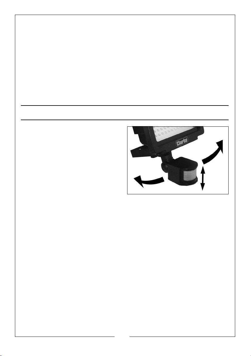
ADJUSTING THE FIELD OF DETECTION
The field of detection of the infrared
sensor can be adjusted 30 degrees in
either horizontal or vertical direction.
By means of horizontal adjustment,
the permanent 180
can be infinitely directed to the right
or left of the mounting position.
By vertical adjustment, the detection
range can be reduced or
lengthened. This can be used to
reduce to incidence of unwanted activation caused by movements from
neighbours and from the street.
The best sensing is achieved by approaching the field of detection
perpendicular to its axis.
A delayed response is often obtained if the field of detection is approached
along the direction of its axis.
o
field of detection
9
Parts & Service: 020 8988 7400 / E-mail: Parts@clarkeinternational.com or Service@clarkeinternational.com

POSSIBLE PROBLEMS
Boiler flues which may discharge vapour or any similar hot air or smoke
movement can cause the light to switch on when it is not required to do so.
Passing cars (with warm engines) or the motion of nearby trees and bushes,
sudden changes in temperature and gusts of wind can also cause the light to
switch on.
If the light has been placed under a roof or under trees, it may also come on
during daylight hours.
If the light does not work, the power supply could be defective or there may
have been a failure in the electrical circuit.
If the temperature difference between the object to be detected and
surrounding area is too small (in the summer for example), the light will react
later. The range of detection may then be10 meters instead of 10 meters for
example.
PARTS REPLACEMENT
Immediately replace a cracked or broken protective glass. Always use original
parts for this which can be purchased on request from your Clarke spares
department.
There are no other user serviceable parts inside the light. DO NOT disassemble
the unit.
10
Parts & Service: 020 8988 7400 / E-mail: Parts@clarkeinternational.com or Service@clarkeinternational.com

DECLARATION OF CONFORMITY
11
Parts & Service: 020 8988 7400 / E-mail: Parts@clarkeinternational.com or Service@clarkeinternational.com

 Loading...