

Page 1
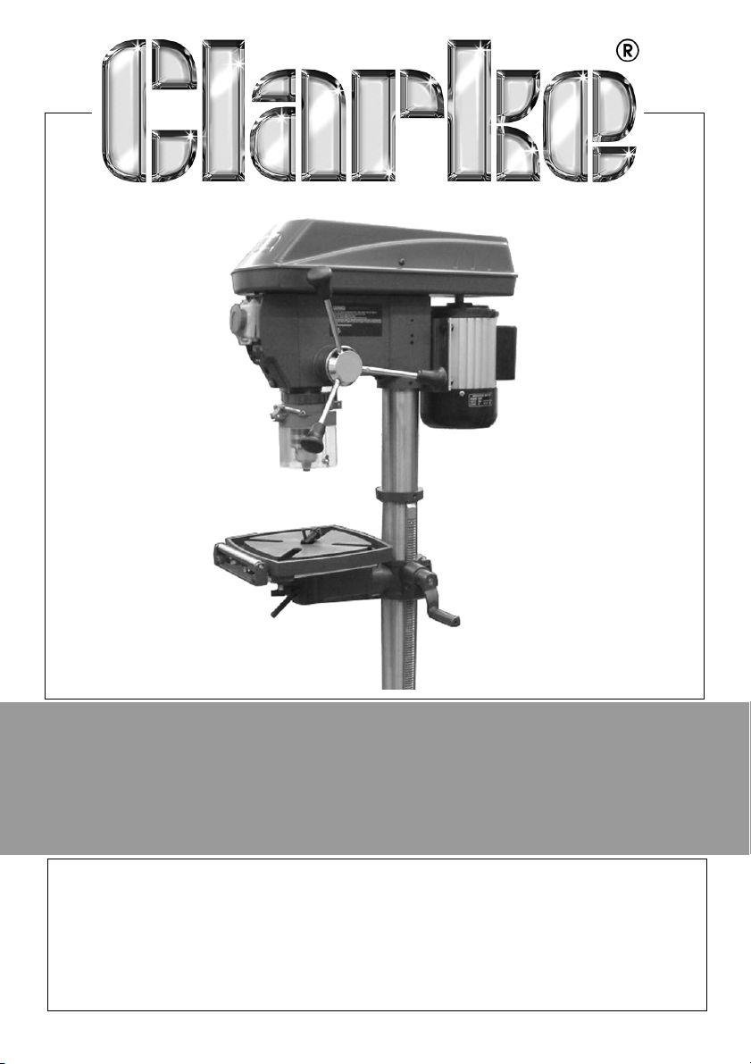
VARIABLE SPEED DRILL PRESS
MODEL NO: CDP350V
PART NO: 6500267
OPERATING & MAINTENANCE
INSTRUCTIONS
GC0415
Page 2

INTRODUCTION
Thank you for purchasing this CLARKE Drill Press.
Before attempting to use this product, please read this manual thoroughly and
follow the instructions carefully. In doing so you will ensure the safety of yourself
and that of others around you, and you can look forward to your purchase
giving you long and satisfactory service.
GUARANTEE
This product is guaranteed against faulty manufacture for a period of 12
months from the date of purchase. Please keep your receipt which will be
required as proof of purchase.
This guarantee is invalid if the product is found to have been abused or
tampered with in any way, or not used for the purpose for which it was
intended.
Faulty goods should be returned to their place of purchase, no product can
be returned to us without prior permission.
This guarantee does not effect your statutory rights.
ENVIRONMENTAL RECYCLING POLICY
Through purchase of this product, the customer is taking on the obligation to
deal with the WEEE in accordance with the WEEE regulations in relation to the
treatment, recycling & recovery and environmentally sound disposal of the
WEEE.
In effect, this means that this product must not be disposed of with general
household waste. It must be disposed of according to the laws governing
Waste Electrical and Electronic Equipment (WEEE) at a recognised disposal
facility.
2
Parts & Service: 020 8988 7400 / E-mail: [email protected] or [email protected]
Page 3
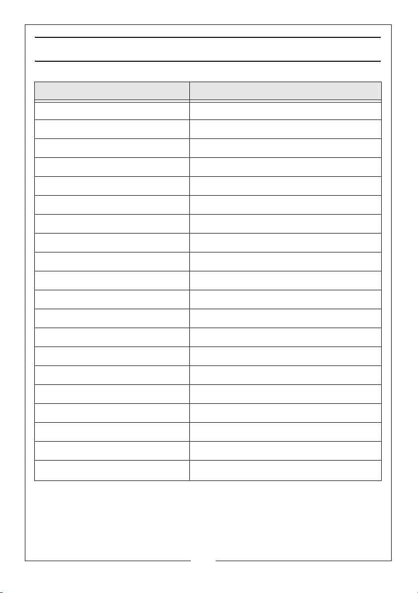
SPECIFICATION
Feature Specification
Weight 43.6 kg
Dimensions (L x W x H) 544 x 329 x 1515 mm
Base length & width 430 255 mm
Throat (chuck to table) 35 - 693 mm
Table Dimensions 240 x 240 mm
Spindle to Column 153 mm
Chuck Capacity 3-16 mm
Spindle Taper B16
Table Tilt Range 90 deg (45deg left/right)
Table Rotation Range 220 deg
Table Height Adjustment Rack & Pinion
Capacity (chuck to base) 1136 mm
Motor 220-240V / 50 Hz
Input Power/current@rated load 550 W / 2.3 A
Output @ rated load 375 W
Drill Speed 450-2475 rpm
Laser Class II
Sound Pressure Level No load 65.5 / Loaded 69.2 lpA dB(A)
Measured Sound Power Level No load 76.4 / Loaded 78.6 lpA dB(A)
Vibration
Please note that the details and specifications contained herein, are correct
at the time of going to print. However, CLARKE International reserve the right
to change specifications at any time without prior notice.
Parts & Service: 020 8988 7400 / E-mail: [email protected] or [email protected]
<2.5 m/s
2
3
Page 4

GENERAL SAFETY RULES
CAUTION: FAILURE TO FOLLOW THESE PRECAUTIONS COULD RESULT IN
PERSONAL INJURY, AND/OR DAMAGE TO PROPERTY.
GENERAL SAFETY IN THE WORKPLACE
1. ALWAYS ensure that air can circulate around the machine and that the air
vents are unobstructed.
2. ALWAYS keep work area clean & tidy. Cluttered work areas and benches
invite accidents.
3. NEVER over-reach. Keep proper footing and balance at all times.
4. NEVER use or store equipment in a wet/damp environment or expose to
rain.
5. KEEP children and bystanders at a safe distance from work area.
6. NEVER operate a machine when under the influence of alcohol, drugs or
medication.
7. ALWAYS ensure the workplace is well lit. Ensure that lighting is placed so that
you will not be working in your own shadow.
CARE & USE OF THE EQUIPMENT
1. ALWAYS check for any damage or any condition that could affect the
operation of the machine. Any damaged part should be properly
repaired.
2. NEVER remove the cover panel unless the machine is disconnected from
the supply, and never use the machine with cover panels removed.
3. NEVER attempt any electrical or mechanical repair unless you are a
qualified technician. If you have a problem with the machine contact your
local CLARKE dealer.
4. NEVER use this product for any other purpose than that described in this
booklet.
5. NEVER abuse the mains cable by yanking the cable to disconnect it from
the socket. Keep the cable away from sharp edges/hot surfaces.
6. NEVER stand on the machine. Serious injury could occur if the machine
topples over.
7. Avoid accidental starting by making sure the power switch is off before
plugging in the power cable.
4
Parts & Service: 020 8988 7400 / E-mail: [email protected] or [email protected]
Page 5

8. Never leave the machine running unattended until it has come to a
complete stop.
PROTECTIVE CLOTHING
1. Dress properly. Loose clothing, gloves, neckties, rings, bracelets, or other
jewellery may get caught in moving parts. Non-slip footwear is
recommended. Long hair should be tied back.
2. ALWAYS wear safety glasses. Everyday glasses are not safety glasses.
3. Wear a face mask if drilling into any material which produces dust.
CARE OF POWER TOOLS
1. Know your machine. Read the manual carefully. Learn the machines
applications and limitations, as well as the specific potential hazards
peculiar to it.
2. ALWAYS keep the guards in place and in working order.
3. Remove any adjusting keys or wrenches before starting. Form the habit of
checking to ensure that keys, wrenches and tools are removed from the
machine.
4. Don’t force the machine. It will do the job better and safer, at the rate for
which it was designed.
5. Use the correct tool. Don’t force a tool or attachment to do a job for which
it was not designed.
6. ALWAYS maintain tools in top condition. Keep drills sharp and clean for best
and safest performance. Follow instructions for lubricating and changing
accessories.
7. ALWAYS disconnect the machine from the power supply before carrying
out any servicing or changing of accessories.
8. CHECK for any damage before use. Damage to moving parts or major
components should be inspected by a qualified technician before
operating the machine. Contact your local dealer for advice.
ADDITIONAL SAFETY RULES FOR DRILL PRESSES
1. IMPORTANT: You should not operate this machine unless you are thoroughly
familiar with drilling machines and drilling techniques. If there is any doubt
whatsoever you should consult a qualified person.
2. NEVER operate the machine until it is completely assembled and you have
read and understood this entire manual.
3. ALWAYS use clamps, or a drill vice bolted to the table, to hold the work. It
should never be held in bare hands.
5
Parts & Service: 020 8988 7400 / E-mail: [email protected] or [email protected]
Page 6

4. ALWAYS shut off the power and remove the drill bit before leaving the
machine.
5. ALWAYS make all adjustments with the power OFF.
6. ALWAYS use the correct drilling speeds for the drill size and the type of
material being drilled (see page 23).
7. NEVER leave the drill unattended whilst it is running. Turn the machine OFF
and do not leave until it has come to a complete stop.
8. ALWAYS remove and store the drill bits when you have finished with the
machine.
9. CAUTION: This machine is designed for use with drill bits and morticing
attachments only. The use of other cutting tools or accessories could be
hazardous.
10. NEVER attempt to drill into a workpiece that does not have a flat surface
unless a suitable support is used.
11. ALWAYS stop the drill before removing workpieces, work supports or swarf
from the table.
12. ALWAYS Make sure you remove the chuck key before turning the machine
on.
13. Adjust the table or depth stop to avoid drilling into the table surface.
14. ALWAYS be sure that the drill bit is securely locked in the chuck.
15. NEVER assemble or set up any work on the table while the drill is running.
16. ALWAYS ensure the table lock is tight before starting the drill.
17. ALWAYS keep hands and fingers away from the drill bit.
WARNING: DUST GENERATED FROM CERTAIN MATERIALS CAN BE
HAZARDOUS TO YOUR HEALTH. ALWAYS OPERATE THE DRILL IN A WELL
VENTILATED AREA. USE A DUST COLLECTION SYSTEM WHENEVER
POSSIBLE.
LASER SAFETY
The laser light beam used in this system is Class II. These lasers do not normally
present an optical hazard, although staring at the beam may cause flash
blindness.1
WARNING: DO NOT STARE DIRECTLY AT THE LASER BEAM! A HAZARD MAY
EXIST IF YOU DELIBERATELY STARE INTO THE BEAM, PLEASE OBSERVE ALL
THE FOLLOWING SAFETY RULES
1. NEVER aim the beam at any person or object other than the workpiece.
6
Parts & Service: 020 8988 7400 / E-mail: [email protected] or [email protected]
Page 7

2. NEVER project the laser beam into the eyes of others.
3. ALWAYS ensure the laser beam is aimed at a workpiece that does not
possess reflective surfaces as the laser beam could be reflected into the
eyes.
Please keep these instructions in a safe place for future reference.
ELECTRICAL CONNECTIONS
Connect the mains lead to a standard, 230 Volt (50Hz) electrical supply
through an approved 13 amp BS 1363 plug, or a suitably fused isolator switch.
WARNING! THIS APPLIANCE MUST BE EARTHED
IMPORTANT: The wires in the mains lead are coloured in accordance with
the following code:
Green & Yellow...........Earth
Blue ...........Neutral
Brown...........Live
As the colours of the flexible lead of this appliance may not correspond with
the coloured markings identifying terminals in your plug proceed as follows:
• Connect GREEN & YELLOW cord to plug terminal marked with letter
“E” or Earth symbol “”, or coloured GREEN or GREEN & YELLOW.
• Connect BROWN cord to plug terminal marked letter “L” or
coloured RED.
• Connect BLUE cord to plug terminal marked letter “N” or coloured
BLACK.
If this appliance is fitted with a plug which is moulded onto the electric cable
(i.e. non-rewirable) please note:
1. The plug must be thrown away if it is cut from the electric cable. There is a
danger of electric shock if it is subsequently inserted into a socket outlet.
2. Never use the plug without the fuse cover fitted.
3. Should you wish to replace a detachable fuse carrier, ensure that the
correct replacement is used (as indicated by marking or colour code).
4. Replacement fuse covers can be obtained from your local dealer or most
electrical stockists.
5. The fuse in the plug must be replaced with one of the same rating (13
amps) and this replacement must be ASTA approved to BS1363.
7
Parts & Service: 020 8988 7400 / E-mail: [email protected] or [email protected]
Page 8
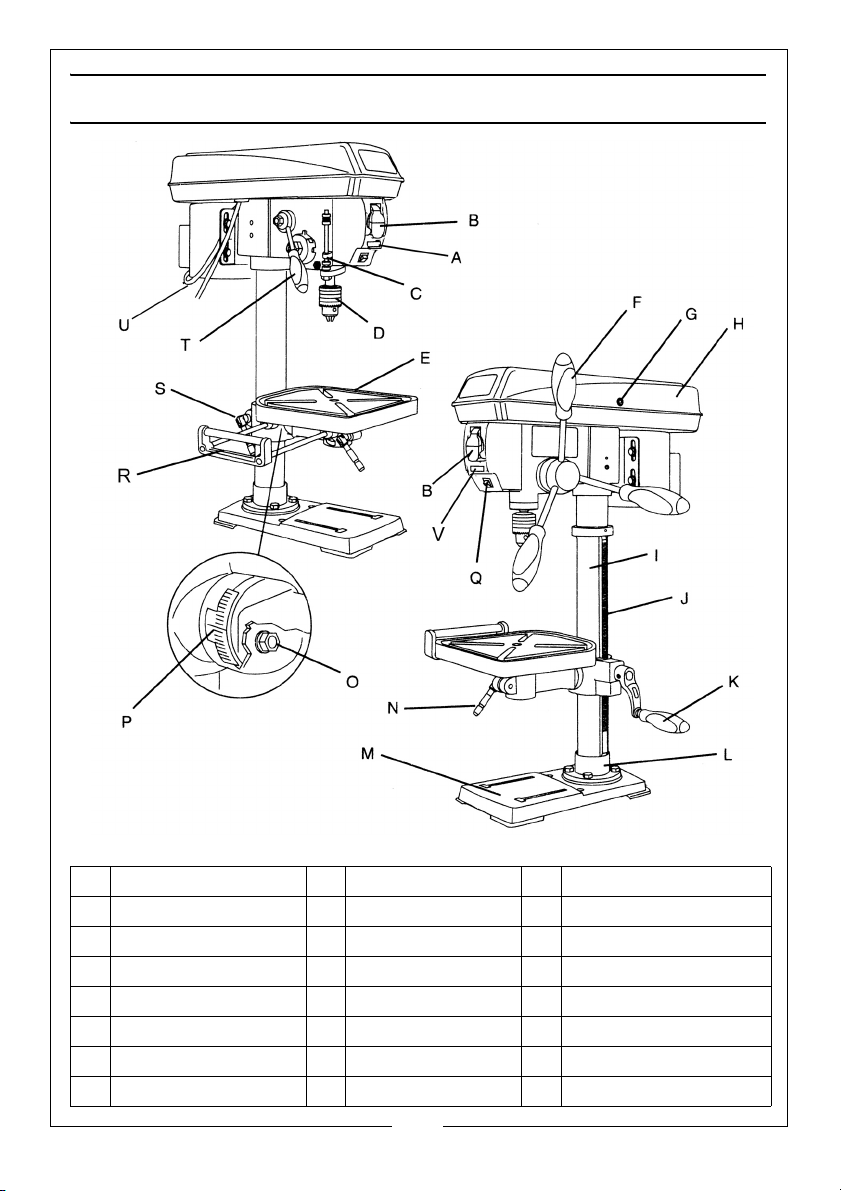
MACHINE LAYOUT
A Digital Speed Display I Column P Bevel Scale
B On/Off Switch J Rack Q Laser Line Switch
C Depth Scale K Crank Handle R Extension Wing/rollers
D Chuck L Column Support S Support Lock Handle
E Table M Base T Speed Control Handle
F Drill Feed handles N Table Lock Handle U Power Cable
G Cover Screw O Table Lock Bolt V Digital Speed Readout
H Drive Cover
8
Parts & Service: 020 8988 7400 / E-mail: [email protected] or [email protected]
Page 9
UNPACKING
When unpacking, check for damage or omissions etc. Any found should be
reported to your CLARKE dealer where the appliance was originally
purchased. Do not discard the packaging until the machine is assembled.
To protect the machine parts from moisture, a protective coating has been
applied to the outside surfaces. Remove this coating with a soft cloth,
moistened with kerosene. Do not use acetone, gasolene or thinners for
cleaning. Apply a coat of paste wax to the table and column and then wipe
all parts with a clean, dry cloth.
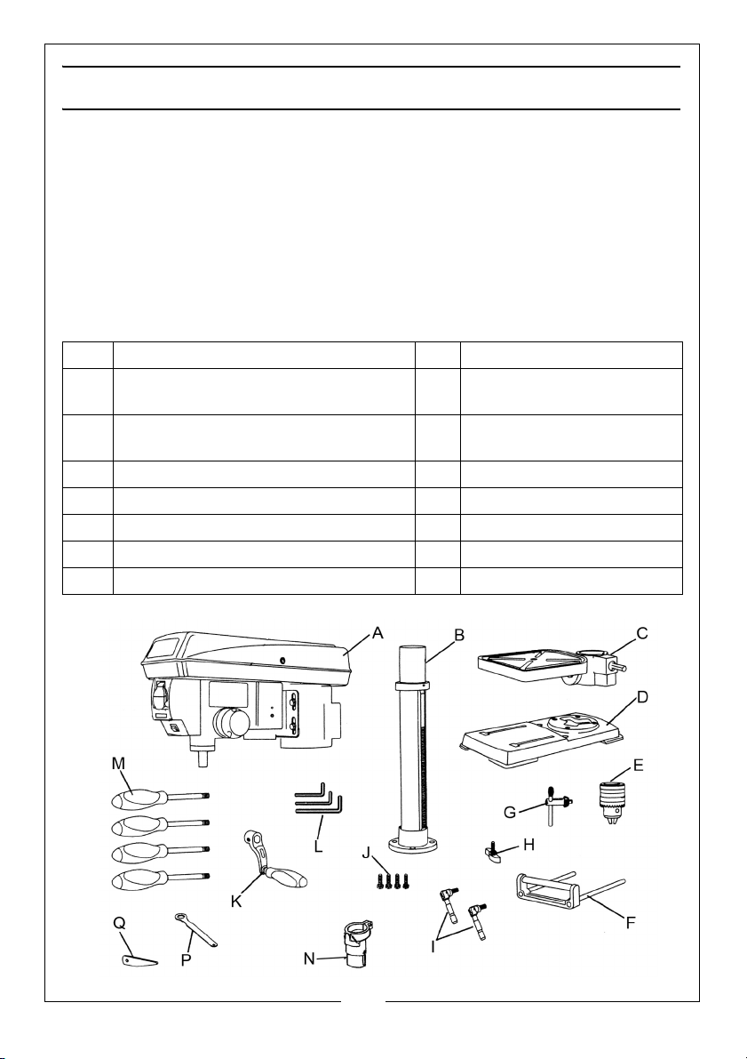
The Drill Press is delivered with the following components:
A Head/motor assembly I Table locking handles (2)
B Column assy (support, column tube,
toothed rack & collar -supplied loose)
C Table with support bracket, worm
drive pinion & spindle
D Base L Hex keys (3)
E Chuck M Feed & speed handles (4)
F Extension wing with rollers N Chuck guard assembly
G Chuck key P Table adjustment wrench
H Wing nuts (2) Q Drift wedge
J Foot/base fixing bolts (4)
K Table crank handle
9
Parts & Service: 020 8988 7400 / E-mail: [email protected] or [email protected]
Page 10
ASSEMBLY & ADJUSTMENTS
ASSEMBLY
WARNING: IF ANY PART IS MISSING OR DAMAGED, DO NOT PLUG THE
BENCH DRILL PRESS IN UNTIL THE MISSING OR DAMAGED PART IS
REPAIRED OR REPLACED AND ASSEMBLY IS COMPLETE.
TOOLS NEEDED FOR ASSEMBLY
• Adjustable wrench or socket set
• Cross-head screwdriver
• Hammer and block of wood
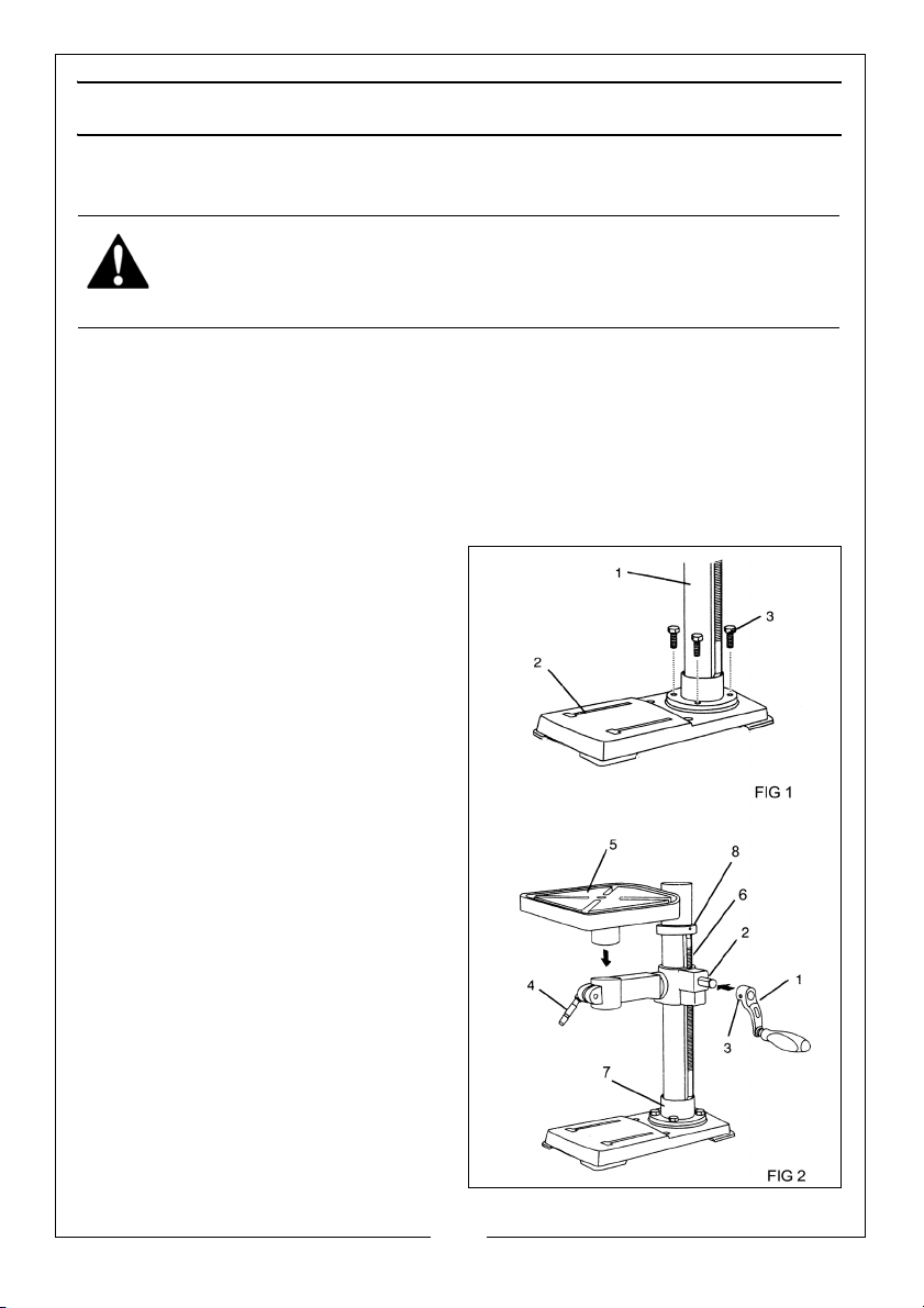
COLUMN ASSEMBLY TO BASE (FIG 1)
1. Place the column tube (1) with its
support, onto the base (2),
aligning the column support holes
with the base holes.
2. Install a bolt (3) in each column
support hole and tighten bolts
using a wrench.
TABLE & SUPPORT BRACKET (FIG 2)
1. Insert the table worm drive spindle
(2) through the table support
bracket from inside before sliding
the crank handle (1) onto the
spindle. Secure in place with the
set-screw (3).
2. Thread the table lock handles (4)
into the front and rear of the table
support bracket.
3. Take the toothed rack (6) and
hold it against the column while
lowering the table support
bracket down the column until
the drive gear meshes with the
rack teeth. Wind the table crank
10
Parts & Service: 020 8988 7400 / E-mail: [email protected] or [email protected]
Page 11
handle to lower the height of the table.
4. Lower the table support bracket and rack until the rack seats in the top lip
of the column support (7).
5. Lower the rack securing collar (8) over the column until it rests over the top
of the rack. Position the table support in the same direction as the base. Fix
the rack securing collar (8) in place with the set-screw.
6. Install the table (5) on its support bracket & tighten the table lock handle
(4).
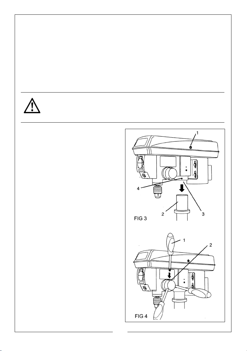
DRILL PRESS HEAD TO COLUMN (FIG 3)
CAUTION: THE DRILL HEAD ASSEMBLY IS HEAVY. TO AVOID INJURY, TWO
PEOPLE SHOULD LIFT IT INTO POSITION.
1. Carefully lift the drill press head
assembly (1) and position it with its
mounting opening (3) over the top
of the column (2). Swivel the
assembly to ensure it is seated
properly on the column.
2. Align the direction of the drill press
head with the direction of the
base and the table.
3. Tighten the set screw (4) using a
hexagon key.
FEED HANDLES (FIG 4)
1. Screw the three feed handles (1)
into the threaded holes in the feed
hub (2) and tighten by hand.
NOTE: When using the drill, one or
two of the feed handles may
be removed if an unusuallyshaped workpiece interferes
with handle rotation.
11
Parts & Service: 020 8988 7400 / E-mail: [email protected] or [email protected]
Page 12
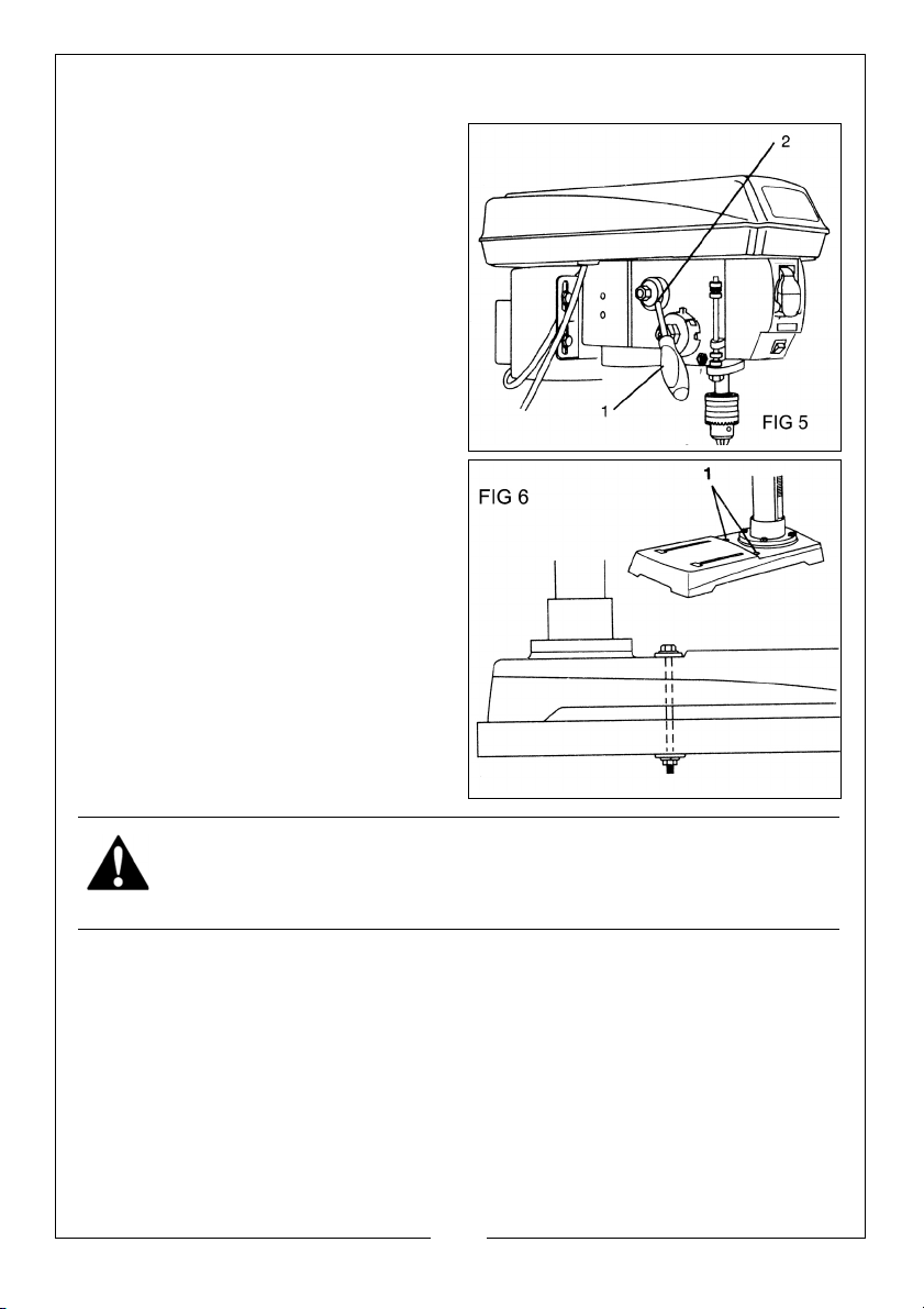
SPEED HANDLE (FIG 5)
REVERSE
REVERSE
1. Screw the feed handle (1) into the
threaded hole on the speed hub
(2) and manually tighten the
handle.
MOUNT THE DRILL PRESS (FIG 6)
1. The drill press must be securely
fastened through the mounting
holes (1) to a stand or floor with
heavy-duty fasteners (not
supplied). This will prevent the
machine from tipping over, sliding,
or walking during operation.
WARNING: DISCONNECT THE DRILL PRESS FROM THE POWER SOURCE
BEFORE INSTALLING, ADJUSTING, OR REMOVING THE CHUCK.
12
Parts & Service: 020 8988 7400 / E-mail: [email protected] or [email protected]
Page 13
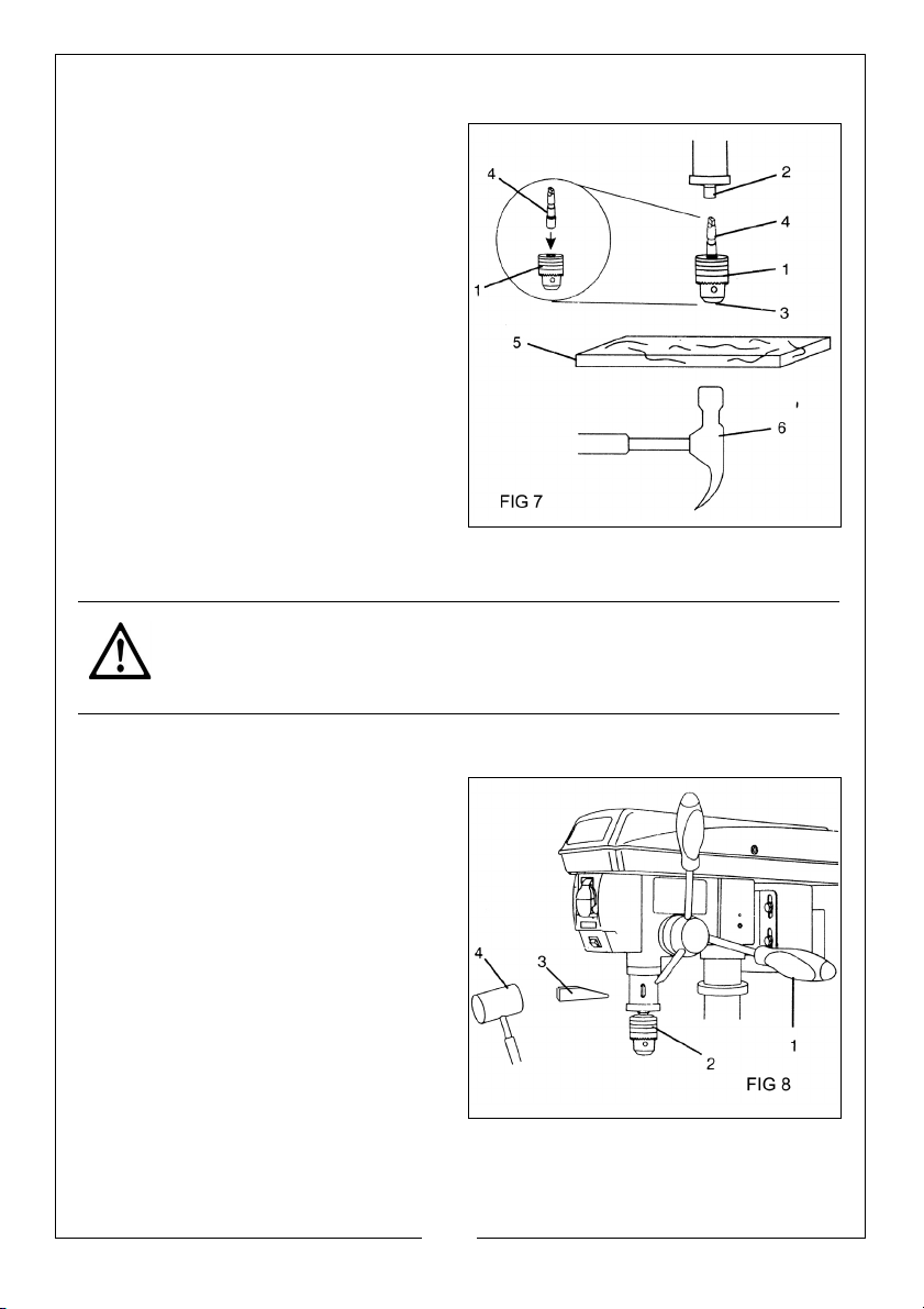
INSTALL THE CHUCK (FIG 7)
REVERSE
REVERSE
1. Inspect and clean the taper hole
in the chuck (1) and the spindle
(2). Remove all grease, coatings &
particles from the chuck and
spindle surfaces with a clean
cloth.
2. Open the chuck jaws (3) by
manually turning the chuck barrel
clockwise. Make sure the jaws are
completely recessed inside the
chuck.
3. Insert the chuck arbor (4) into the
opening at the top of the chuck
(1).
4. Seat the chuck and chuck arbor
on the spindle by placing a block
of wood (5) under the chuck (1) and tapping the wood with a hammer (6)
or tap the chuck with a rubber mallet.
CAUTION: TO AVOID DAMAGING THE CHUCK, MAKE SURE THE JAWS
ARE COMPLETELY RECESSED INTO THE CHUCK. DO NOT USE A METAL
HAMMER TO DRIVE THE CHUCK INTO THE SPINDLE.
TO REMOVE THE CHUCK (FIG 8)
1. Turn the feed handles (1) to lower
the chuck (2) to the lowest
position.
2. Place a tapered drift key (3) into
the corresponding slot in the quill
assembly and tapped lightly with
a mallet (4) to release the
tapered chuck spindle. The chuck
can then be supported over a
tube or vice and the spindle
driven out with a hammer and
suitably sized parallel punch.
Parts & Service: 020 8988 7400 / E-mail: [email protected] or [email protected]
13
Page 14
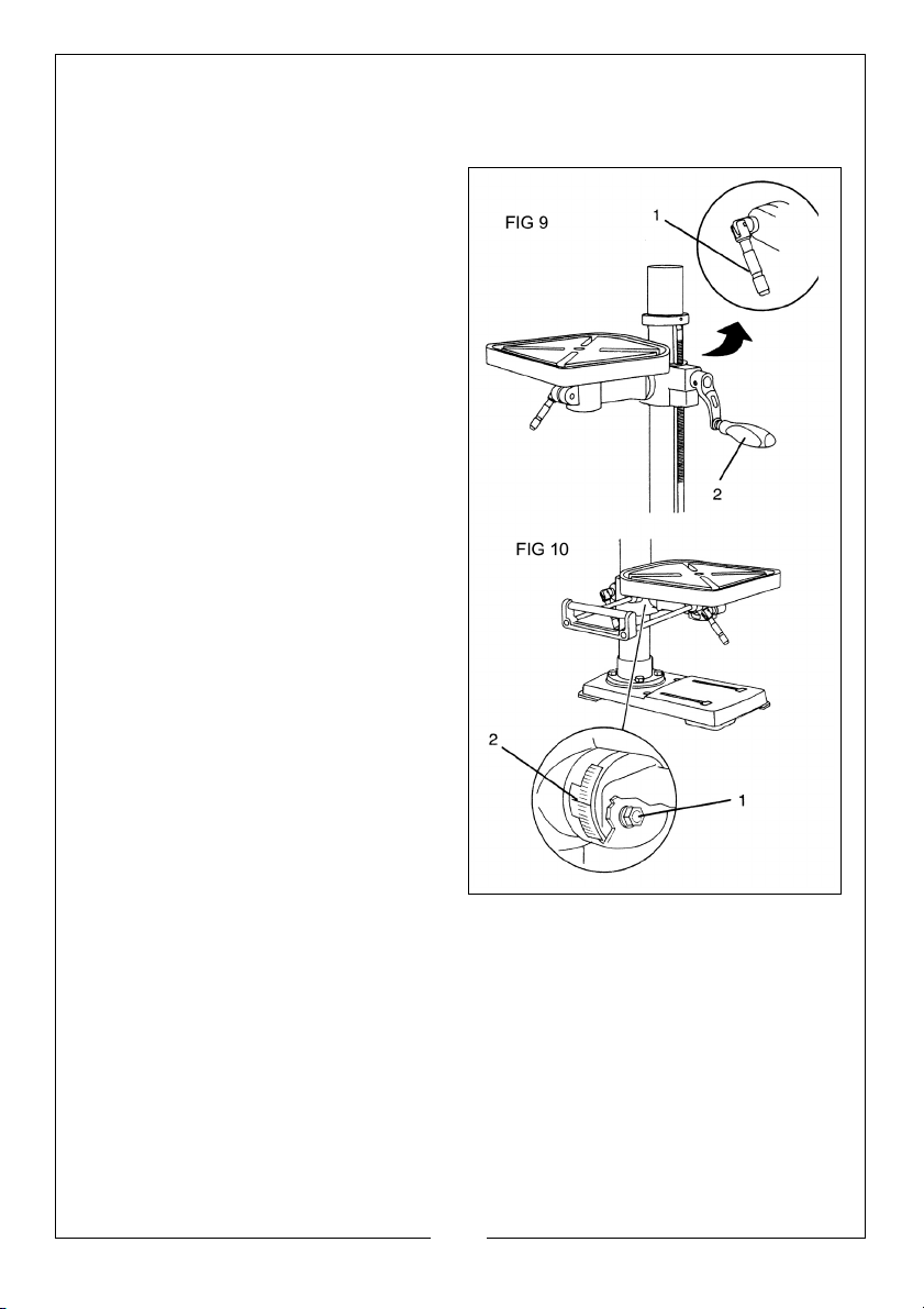
ADJUSTMENTS
TO RAISE & LOWER THE TABLE (FIG 9)
1. Loosen the support lock handle
(1) and turn the crank handle (2)
until the table is at the desired
height.
2. Tighten the table lock before
drilling.
TO ROTATE THE TABLE (FIG 9)
1. Loosen the support lock handle
(1) & turn the table around the
column to the desired position.
NOTE: The rack should rotate
around the column with the
table support bracket. If the
rack binds and will not
rotate, slightly loosen the set
screw in the rack collar.
2. Tighten the support lock before
drilling.
TO TILT THE TABLE (FIG 10)
1. Loosen the bevel lock bolt (1).
2. Tilt the table to the desired angle,
using the bevel scale (2) as a
basic guide.
• Check the angle using a
protractor or square for greater
accuracy.
3. Re-tighten the bevel lock bolt.
4. To return the table to its original horizontal position, loosen the bevel lock
bolt (1).
5. Re-align the table to the 0° setting.
6. Tighten the bevel lock bolt with the wrench.
14
Parts & Service: 020 8988 7400 / E-mail: [email protected] or [email protected]
Page 15
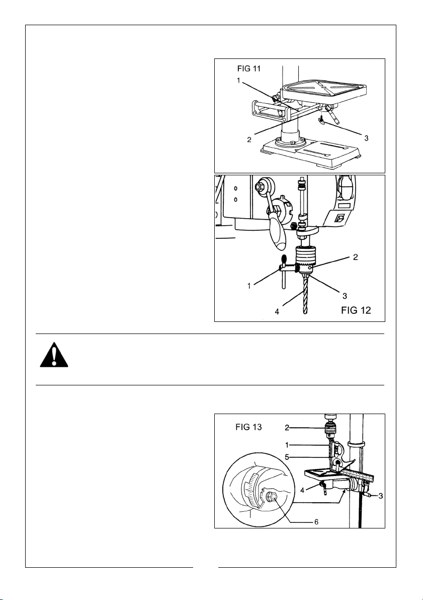
INSTALL THE TABLE EXTENSION (FIG11)
REVERSE
1. Insert the two rods (1) of the table
extension into the channels (2) at
each side of the table.
2. Screw a wing knob (3) into the
bottom of each channel and
tighten to secure the extension to
the table.
TO INSTALL DRILL BITS (FIG 12)
1. Engage the chuck key (1) with the
chuck (2) and turn counterclockwise to open the jaws (3).
2. Insert a drill bit (4) into the chuck,
far enough to obtain maximum
gripping of the chuck jaws.
3. Centre the drill bit in the chuck
jaws before final tightening.
4. Tighten the chuck jaws using the
chuck key to ensure that the drill
bit will not slip while drilling.
5. Remove the chuck key.
WARNING: TO AVOID INJURY, MAKE SURE THAT THE CHUCK KEY IS
REMOVED FROM THE CHUCK BEFORE STARTING ANY DRILLING
OPERATION.
TO SQUARE THE TABLE TO THE DRILL BIT (FIG 13)
1. Insert a 3" (7.6 cm) long drill bit (1)
into the chuck (2) and tighten the
jaws with the chuck key.
2. Raise the table using the crank
handle (3), and secure the table
with the locking handle (4)
approximately 1" (2.5 cm) below
the drill bit.
3. Place a combination square (5)
on the table as shown, Make sure
the drill bit is parallel or aligned exactly to the straight edge of the square.
15
Parts & Service: 020 8988 7400 / E-mail: [email protected] or [email protected]
Page 16
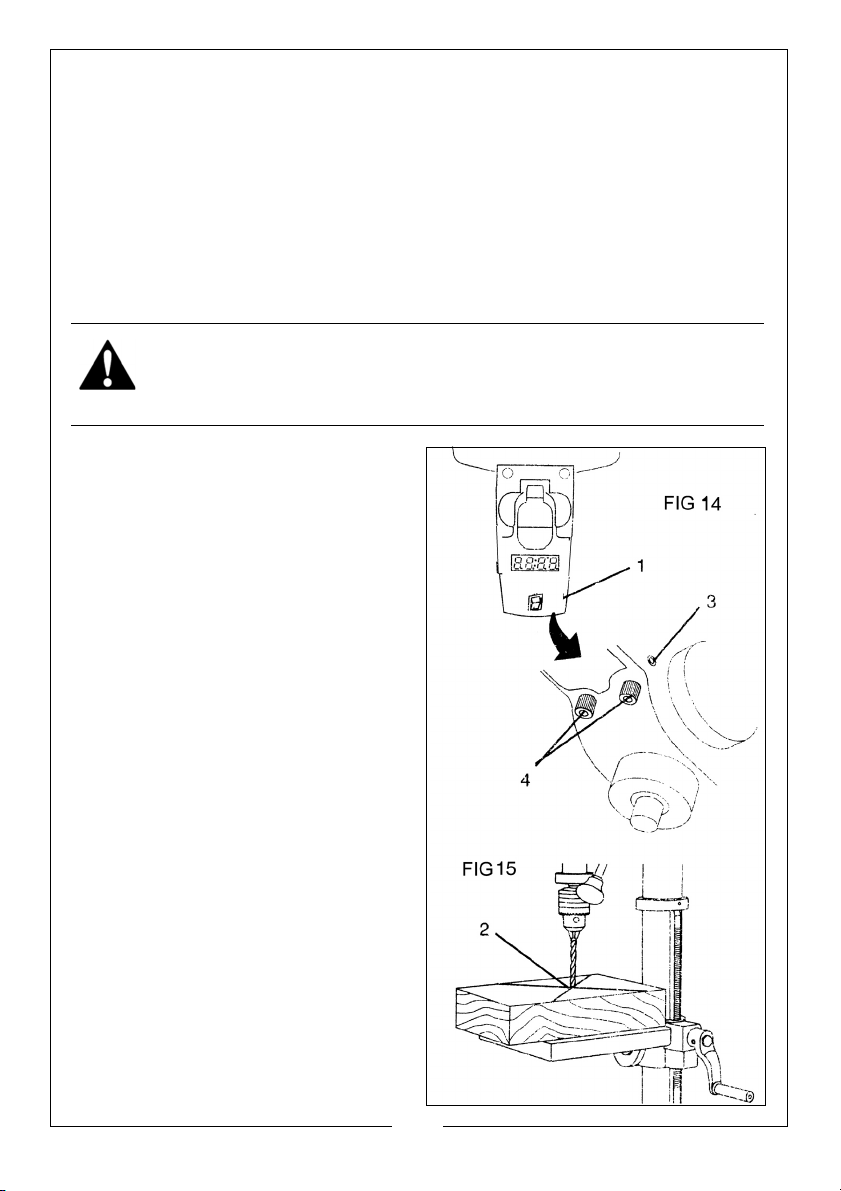
4. If adjustment is needed, loosen the bevel lock bolt (6) with a wrench.
5. Tilt the table slightly until the combination straight edge is aligned perfectly
with the drill bit.
6. Tighten the bevel lock when aligned perfectly.
NOTE: Adjustments for the correct function of your drill press return spring
have been done at the factory. Please do not modify them.
However, prolonged use of the drill press may make some readjustment necessary.
TO USE THE LASER LINE (FIGS 14 & 15)
WARNING: DO NOT STARE DIRECTLY AT THE LASER BEAM! A HAZARD MAY
EXIST IF YOU DELIBERATELY STARE INTO THE BEAM, PLEASE OBSERVE ALL
SAFETY RULES.
1. Place a workpiece on the table.
2. Turn the laser switch (1) to the ON
position.
3. Lower the drill bit to meet the
workpiece (2). The two laser lines
should cross where the drill meets
the workpiece.
4. If the laser needs to be adjusted:
a. Using a 3 mm hex key, turn the
laser adjustment set screws (3)
counter-clockwise.
b. Rotate the laser light housing
(4) until the two laser lines
intersect where the drill meets
the workpiece. DO NOT stare
directly at the laser lines.
5. Re-tighten the adjustment setscrews (3).
SPINDLE RETURN SPRING (FIG 16)
The spindle is equipped with an autoreturn mechanism comprising a
spring and a notched housing. The
spring tension was set at the factory
and should not be adjusted unless
absolutely necessary.
16
Parts & Service: 020 8988 7400 / E-mail: [email protected] or [email protected]
Page 17
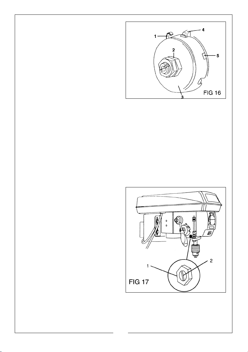
1. Unplug the drill press.
2. Place a screwdriver into the loop
(1) to hold the spring in place.
3. Loosen the two housing nuts (2)
approximately 1/4" (6 mm). Do
not remove the nuts from the
threaded shaft. Do not allow the
spring or spring housing to slip out
of control.
4. While firmly holding the spring
housing (3), carefully pull the
spring housing out until it clears the raised notch (4).
5. Turn the housing so that the next notch (5) is engaged with the raised
notch (4).
• To increase the spindle return tension, turn the spring housing
counter-clockwise.
• o decrease the tension, turn the spring housing clockwise.
6. Tighten the two housing nuts but not excessively. If the nuts are tightened
too much, the movement of the spindle and feed handles will become
sluggish.
ANGULAR "PLAY" OF THE SPINDLE (FIG 17)
Move the spindle to the lowest
downward position and hold in
place. Try to make the spindle
revolve around its axis while also
moving it with a side motion. If there is
too much play, proceed as follows:
1. Loosen the locknut (1).
2. Without obstructing the upward
and downward motion of the
spindle, turn the screw (2)
clockwise to eliminate the play.
NOTE: A little play is normal.
3. Tighten the locknut (1).
17
Parts & Service: 020 8988 7400 / E-mail: [email protected] or [email protected]
Page 18
OPERATION
REVERSE
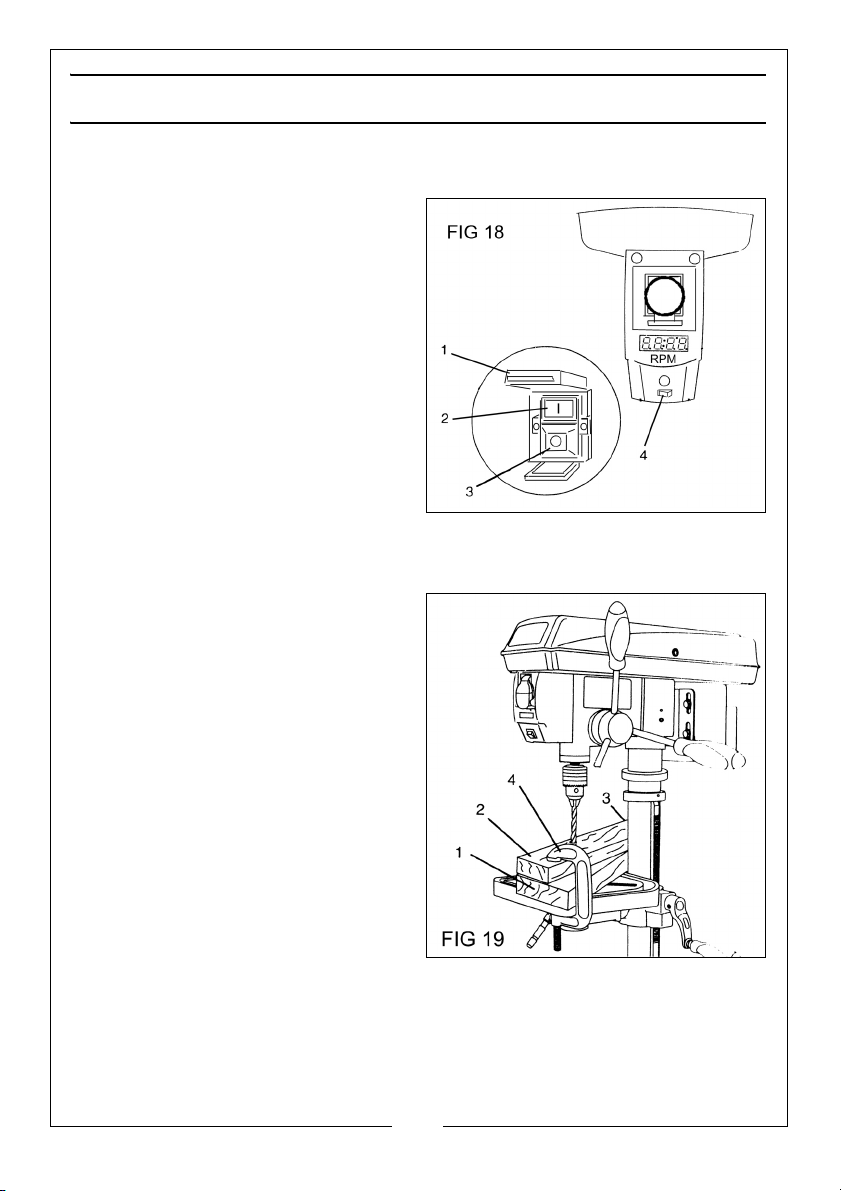
ON/OFF SWITCH (FIG 18)
1. To turn the drill press ON, slide the
red cover guard (1) upwards to lift
it away and access the ON/OFF
buttons. Press the green pushbutton (2) to start the machine.
• As a safety feature, the ON
button cannot be pressed
without raising the guard.
2. To turn the drill press OFF, press
either the OFF button (3) if holding
the guard raised or press the
guard cover at any time.
LASER LINE ON/OFF SWITCH (FIG 19)
The laser line switch (4) is located below the ON/OFF switch.
POSITION THE TABLE AND WORKPIECE (FIG 19)
Always place a piece of backup
material (1) such as wood, plywood,
etc, on the table underneath the
workpiece (2).
This will prevent splintering on the
underside of the workpiece as the
drill bit breaks through.
To keep the material from spinning
out of control, it must contact the left
side (3) of the column as illustrated, or
be clamped (4) to the table.
NOTE: For small workpieces that
cannot be clamped to the
table, use a drill press vice
(not i ncluded). Th e vice mu st
be securely clamped or
bolted to the table.
Parts & Service: 020 8988 7400 / E-mail: [email protected] or [email protected]
18
Page 19
GENERAL DRILLING GUIDELINES
REVERSE
WARNING: TO PREVENT THE WORKPIECE AND THE BACKUP MATERIAL
FROM SLIPPING FROM YOUR HAND WHILE DRILLING, POSITION
WORKPIECE AND BACKUP MATERIAL TO THE LEFT SIDE OF THE COLUMN. IF
THE WORKPIECE AND THE BACKUP MATERIAL ARE NOT LONG ENOUGH
TO REACH THE COLUMN, CLAMP THE WORKPIECE AND BACKUP
MATERIAL TO THE TABLE. FAILURE TO DO THIS COULD RESULT IN INJURY.
TO DRILL A HOLE
1. Mark where you want to drill on the workpiece by using a centre punch or
turn ON the Laser Line to mark the drilling point.
2. Clamp the workpiece in place. Before turning on the drill, turn the feed
handles to bring the drill bit down. Line the drill bit tip up with the mark.
3. Turn on the drill and pull down on the feed handles with appropriate force
needed to allow the drill bit to drill into the material.
NOTE: FEEDING TOO SLOWLY might cause the drill bit to turn in the chuck.
FEEDING TOO RAPIDLY might stop the motor, cause the belt to slip,
force the workpiece loose, or break the drill bit. Practice with
scrap material to get the feel of the machine before attempting
any drilling operation.
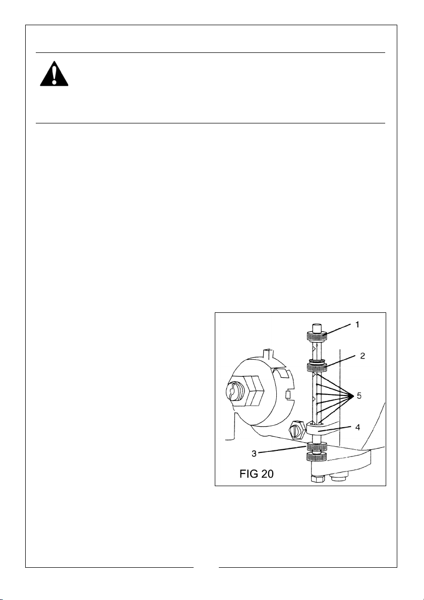
TO ADJUST DRILLING DEPTH (FIG 20)
The depth gauge controls the
maximum distance the drill bit will
move up or down.
To stop the drill bit at a pre-measured
depth:
1. Rotate the upper depth knob (2)
until the bottom of the knob is
aligned with the desired depth
mark (5) on the gauge scale.
2. Rotate the depth scale lock knob
(1) until it meets the lower depth
scale knob (3). The chuck will stop
after descending to the selected
height.
TO ADJUST QUILL (RETURN) HEIGHT (FIG 20)
To adjust the upward distance the quill (the shaft that moves up and down)
can travel.
1. Turn the feed handles until the quill is at the desired height & hold it there.
19
Parts & Service: 020 8988 7400 / E-mail: [email protected] or [email protected]
Page 20
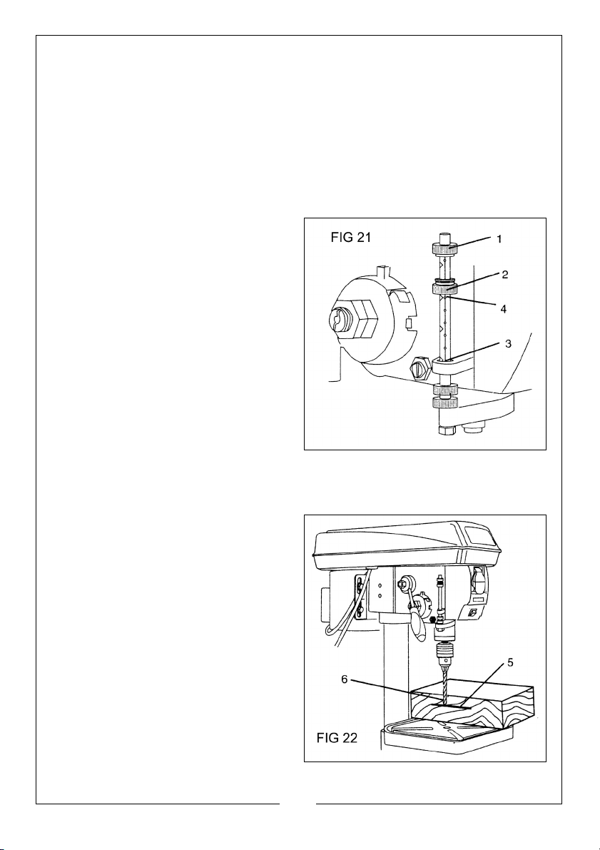
2. Rotate the lower depth knob (3) until it rests against the bottom of the
metal gauge support (4).
Drilling an unmeasured blind hole (not all the way through the workpiece) to a
given depth can be done two ways: using the depth scale method or
workpiece method.
DEPTH SCALE METHOD (FIG 21)
1. Make sure the 0 (" or mm) mark on the depth gauge rests at the top edge
of the metal support (3) when the quill is fully retracted.
2. Put the workpiece on the table,
and raise the table until the tip of
the drill bit just touches the top of
the workpiece. Lock the table in
place.
3. Determine the drill depth for this
workpiece.
4. Rotate the lower depth knob (2)
until it is aligned with the desired
depth mark (4) (for example, 1")
on the gauge scale.
5. Rotate the upper depth lock knob
(1) until it meets the lower depth
knob (2). The chuck will be
stopped at the distance selected on the depth scale.
WORKPIECE METHOD (FIG 21 & 22)
1. Mark the desired depth (5) of the
drill hole on the side of the work.
2. With the drill press in the OFF
position, bring the drill bit (6) down
until the tip is level with the mark.
3. Holding the feed handles at this
position, rotate the lower depth
knob (2) until it meets the metal
support.
4. Rotate the upper depth scale
lock knob (1) until it meets the
lower knob (2). The chuck and the
drill bit will now be stopped at the
distance selected on the depth
scale.
20
Parts & Service: 020 8988 7400 / E-mail: [email protected] or [email protected]
Page 21
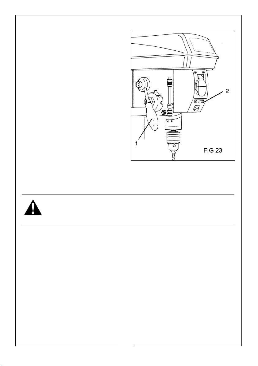
MECHANICAL VARIABLE SPEED (FIG. 23)
REVERSE
To increase or decrease the speed
when operating, raise or lower the
speed handle (1). The speed (rpm) is
displayed by the digital readout.
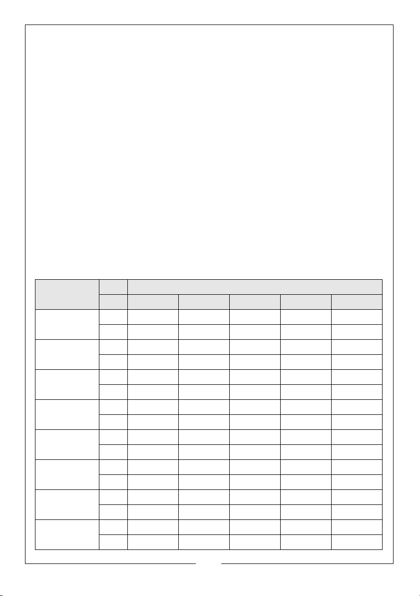
Use the table on page 23 to
determine the recommended speed
for the drill size you are using and the
type of material you are to drill.
Check the speed on the digital
speed read-out (2) while drilling.
DRILLING SPEEDS
Important factors when determining
the best drilling speed are:
• Material type
•Hole size
• Drill bit or cutter type
• Quality desired
Generally, smaller drill bits require greater speed than large drill bits. Softer
materials require greater speed than harder materials. See page 23 for
approximate recommended speeds for the workpiece material.
WARNING: DO NOT ATTEMPT TO CHANGE THE DRIVE SPEED WHEN THE
DRILL PRESS IS TURNED OFF.
DRILLING METAL
• Use metal-piercing twist drill bits.
• It is always necessary to lubricate the tip of the drill with oil to prevent
overheating the drill bit.
• All metal workpieces should be clamped down securely. Any tilting,
twisting, or shifting causes a rough drill hole, and increases the
potential of drill bit breakage.
• Never hold a metal workpiece with your bare hands. The cutting
edge of the drill bit may seize the workpiece and throw it, causing
injury. The drill bit will break if the metal piece hits the column.
• If the metal is flat, clamp a piece of wood under it to prevent
turning. If it cannot be laid flat on the table, then it should be
blocked and clamped.
21
Parts & Service: 020 8988 7400 / E-mail: [email protected] or [email protected]
Page 22
DRILLING WOOD
Brad point bits are preferred. Metal piercing twist bits may be used on wood.
Do not use auger bits which turn so rapidly that they can lift the workpiece off
the table and whirl it around.
Always protect the drill bit by positioning the table so that the drill bit will enter
the centre hole when drilling through the workpiece.
To prevent splintering, feed drill bit slowly when the bit is about to cut through
to the reverse side of the workpiece.
To reduce splintering and protect the point of the bit, use scrap wood as a
backing or a base block under the workpiece.
FEEDING THE DRILL BIT
Pull down on the feed handles with only enough force to allow the drill bit to
cut.
FEEDING TOO RAPIDLY could stall the motor, cause the belt to slip, damage
the workpiece, or break the drill bit.
FEEDING TOO SLOWLY could cause the drill bit to heat up and burn the
workpiece.
Material Units Speed Range (rpm)
2000-2475 1400-2000 1000-1400 750-1000 450-750
Wood In 3/8 5/8 7/8 1.1/4 1.5/8
mm 9.5 16 22 31.75 41
Zinc &
Diecast
Aluminium &
Brass
In 1/4 3/8 1/2 5/8 3/4
mm 6.4 9.5 12.5 16 19
In 3/16 3/8 1/2 11/16 3/4
mm 4.8 9.5 12.5 17.5 19
Plastics In 3/16 5/16 7/16 9/16 11/16
mm 4.8 7.9 11 12.5 13.5
Cast Iron &
Bronze
Mild Steel &
Maleable
Cast Steel
Med Carbon
Stainless &
Tool Steel
In 1/8 1/4 11/32 1/2 3/4
mm 3.2 6.4 8.75 12.5 19
In 3/32 5/32 1/4 3/8 5/8
mm 2.4 4 6.4 9.5 16
In 1/16 1/8 1/4 3/8 5/8
mm 1.6 3.2 6.4 9.5 16
In 3/64 1/16 1/8 1/4 - - - - - -
mm 1.2 1.6 3.2 6.4 - - - - - -
22
Parts & Service: 020 8988 7400 / E-mail: [email protected] or [email protected]
Page 23

MAINTENANCE
For maximum performance, it is essential that the machine is properly
maintained. Always inspect before use. Any damage should be repaired and
faults rectified.
If the mains lead is damaged it should be replaced immediately.
Please refer to TROUBLESHOOTING on page 25. If you are unable to rectify any
faults, please contact your local dealer or Clarke International Service
Department on 0208 988 7400 for assistance.
AFTER USE
Always remove drill bits, and store in a safe place. The machine requires very
little maintenance other than the following guidelines.
1. Vacuum clean any dust or swarf that accumulates in or on the motor, drive
housing, table and work surface.
2. Lubricate the table bracket and locking handles if they become difficult to
use. Components should be dry, with machined surfaces lightly oiled.
3. Check all cables periodically for security, and that they are in good
condition and not cracked.
IMPORTANT: Disconnect from mains power before cleaning.
MONTHLY (when in constant use)
1. Check tightness of mounting bolts and head and column securing set
screws.
2. Check belt for wear and replace if frayed or otherwise damaged.
3. Blow out any dust/swarf that may have accumulated in the motor fan.
4. Apply a thin coat of wax paste or light oil to the table and column for
lubrication and to help prevent corrosion.
5. Pull the spindle down and lightly oil the spindle sleeve every three months.
• The ball bearings in the spindle are greased and permanently
sealed at the factory and require no further lubrication.
• DO NOT attempt to carry out repairs yourself, unless you are fully
competent, all work must be carried out by a qualified technician or
the Clarke service department.
23
Parts & Service: 020 8988 7400 / E-mail: [email protected] or [email protected]
Page 24
.
REVERSE
WARNING: DISCONNECT THE DRILL PRESS FROM THE POWER SUPPLY
BEFORE OPENING THE COVER.
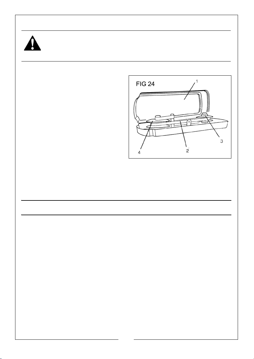
TO REPLACE THE BELT (FIG 24)
Belt tension and drill press speed is
controlled by automatic adjustments
made to the diameter of the front
pulley when the drive handle is
moved.
1. Remove the fixing screw and
open the housing cover (1).
2. Remove the belt (2) from the
housing if it is broken. If it is not
broken, but is too stretched to
operate correctly, work the belt
off the drive (motor) pulley (3).
Then remove the belt from the
front pulley (4).
3. Replace the belt by putting a new belt over the front pulley (4) and
carefully sliding the belt over the drive (motor) pulley (3).
ACCESSORIES
The following range of accessories is available from your Clarke dealer:
Mortising Attachment CMA1B 6500023
Mortise Chisels 6mm 6500025
9mm 6500026
13mm 6500027
16mm 6500028
Drill Press Vices CDV30B 6501901
CDV40B 6501902
CDV50B 6501903
CDV60B 6501904
24
Parts & Service: 020 8988 7400 / E-mail: [email protected] or [email protected]
Page 25

TROUBLESHOOTING
Problem Cause(s) Remedy
Noisy operation 1.Incorrect belt tension.
2.Dry spindle.
3.Loose spindle pulley.
4.Loose motor pulley.
Drill bit burns or
smokes.
Excessive drill
runout or wobble.
Hole is not perfectly round.
Drill bit binds in the
workpiece.
1.Drilling at an incorrect
speed.
2.Swarf is not discharging
from hole.
3.Dull drill bit.
4.Feeding the drill too slowly.
5.No lubrication.
1.Bent drill bit.
2.Bit not correctly installed in
chuck.
3.Worn spindle bearings.
4.Lengths of cutting flutes or
angles not appropriate for
the hardness of the grain.
5.Chuck not properly
installed.
1.Workpiece is pinching the
drill bit.
2.Excessive feed pressure.
Adjust belt tension. See “Belt
Replacement” section
under ADJUSTMENTS.
Lubricate the spindle. See
MAINTENANCE section.
Tighten the retaining nut on
the pulley insert.
Tighten the setscrew on the
side of the motor pulley.
Change the speed. see
“Variable Speed” in
OPERATION section.
Withdraw the bit more frequently to clear swarf.
Re-sharpen or replace bit.
Feed fast enough to cut the
material cleanly.
See “Drilling a hole” under
OPERATION.
Lubricate the drill bit with
cutting oil or motor oil.
Replace the bit.
Re-install the bit. See “To
Install Bits” in ADJUSTMENTS.
Ask your Clarke dealer to
replace bearings.
Re-sharpen the drill bit
correctly or replace with
more suitable type.
Re-install the chuck. See
“Installing the Chuck” in
ASSEMBLY.
Support or clamp the workpiece. See “Position the
Table & Workpiece” in
OPERATION.
Feed more slowly. See
“Feeding the Drill Bit” in
OPERATION.
25
Parts & Service: 020 8988 7400 / E-mail: [email protected] or [email protected]
Page 26

Spindle returns too
slowly or too
1.Spring has incorrect
tension
quickly.
Chuck falls off
spindle.
1.Dirt, grease or oil on the
tapered surface of the
spindle or chuck.
The workpiece
splinters on the
1. No backing material to
support the underside
underside.
The workpiece is
slipping from your
hand.
1. The workpiece needs to
be properly supported or
clamped.
Motor will not run. 1.Defective/broken switch.
2.Damaged power cable.
3. Open circuit, loose
connection or burned out
motor.
4. Blown fuse or circuit
breaker.
5. Low voltage.
Motor will not start
and fuses or circuit breaker trip
out.
Motor fails to
1. Short circuit in motor or
power cable.
2.Incorrect fuses or circuit
breakers.
1.Overloaded circuit.
reach full power
2.Unsuitable extension
cable.
Adjust the spring tension.
See “Spindle Return Spring”
in ADJUSTMENT.
Clean the tapered surface
of both the chuck and the
spindle with a household
detergent. See “To Install the
Chuck” in ASSEMBLY.
Always use a backing
material. See”Position the
Table and Workpiece” in
OPERATION.
Support the workpiece using
the extension wing or
clamps. See “Position of the
Table and Workpiece” in
OPERATION.
Take machine to your
Clarke dealer for repair.
Replace fuse or re-set circuit
breaker. Turn off other
machines on the same
circuit.
Check the power supply for
correct voltage. Use
another circuit or have a
qualified electrician
upgrade the service.
Send to your Clarke dealer
for repair.
Replace with correct fuse or
circuit breaker for the circuit
Turn off other machines and
rectify.
Replace with correct size
extension cable.
26
Parts & Service: 020 8988 7400 / E-mail: [email protected] or [email protected]
Page 27
Motor stalls. 1.Short circuit in motor.
2.Incorrect fuses or circuit
breakers.
3.Overloaded circuit.
4.Low voltage.
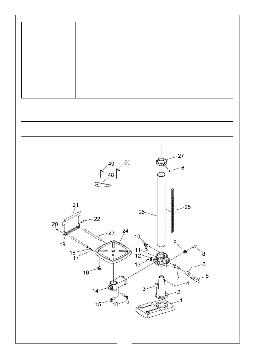
COMPONENT PARTS
Send to your Clarke dealer
for repair.
Replace with correct fuse or
circuit breaker for the circuit
Turn off other machines and
re-try.
Check the power supply for
correct voltage. Use
another circuit or have a
qualified electrician
upgrade the service.
27
Parts & Service: 020 8988 7400 / E-mail: [email protected] or [email protected]
Page 28
Page 29
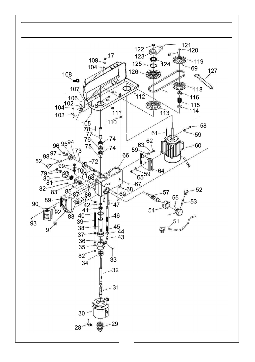
COMPONENT PARTS LIST
No Description Code No Description Code
1 Base DD13301001F 31 Chuck Arbor DD16103007A
2 Column Support DD13401002 32 Spindle DD13303001
3 Hex Bolt M10 x 30mm 33 Screw M6 x 16mm
4 Hex Setscrew M8 x 8mm 34 Bearing SKF6204
5 Handlebar Assy DD13401009 35 Locking Collar W134B08005-1A
6 Hex Setscrew M6 x 10mm 36 Nut M6
7 Worm Drive DD13201008 37 Thumb Nut DDW134080052
8 Gear Pin DD13201007 38 Quill Tube DD13303002
9 Helical Gear DD13201006 39 Lock-depth Bolt DDW134080055
10 Column Clamp DD101013B 40 Quill Gasket DD13303006
11 Table Support DD13401004B 41 Bearing SKF6201
12 Angle Scale DD1346002A 42 Circlip 11mm DD894.1-86
13 Pan Head Screw M4 x 8mm 43 Bolt M8 x 20
14 Table Arm DD13401005 44 Lock Washer DD/T96.2
15 Hex Bolt M16 x 35mm 45 Spring DDW13402033
16 Lock Knob DD13102005B 46 Shaft DDW16302029
17 Pan Head Screw M6 x 12mm 47 Laser Device DDRLM08010
18 Lock Washer DD/T96.2 48 Wedge DD16103008
19 Roller Support W134B01015-1 49 Allen Key S3 DDGB5356-86
20 Screw M6 x 10mm 50 Allen Key S4 DDGB5356-86
21 Roller W134B01015-2 51 Power Cable DLCABB3G14
22 Screw W134B01015-4 52 Handle Knob DD13304011C
23 Guide bar W134B01015-3 53 Handle Arm DD13204005A
24 Table W134B01014 54 Handle Hub DD13304001
25 Toothed Rack DD13201010B 55 16mm Pin DD879-86
26 Column Tube DD13401003 56 Collar DD13304003E
27 Collar DD13401011A 57 Pinion Shaft DD13304002
28 Chuck Key DD1610300E-1 58 Hex Bolt M8 x 25mm
29 Chuck DD1610300E 59 Washer 8mm
30 Chuck Guard DD13308002 60 Motor YLL7124-W03-T
29
Parts & Service: 020 8988 7400 / E-mail: [email protected] or [email protected]
Page 30
No Description Code No Description Code
61 Key (4 x 76) DD1564-79 94 Key 3 x 6 DD1564-79
62 Hex Bolt M8x 12 95 Handle Hub DDW13202032
63 Washer 8mm 96 Locknut DD889.1-2000
64 Mounting Plate DDW13200207 97 Dish Spring DD/T1972-1992
65 Nut M8 98 Handle DD13104005B
66 Head Casing DDW134B02001 99 Adjusting Nut DDW134B08005
67 16mm Pin DD/879-86 100 Washer DDW134B08005
68 Hex Setscrew M8 x 8 101 Tacho Rec Seat DDW134A0509
69 Hex Setscrew M6 x 8 102 Tacho Receiver DD014001100
70 Pin (2.5 x 12) DD/879-86 103 Cable Clip DD16102014A
71 Speed Shaft DDW16302029 104 Screw M5 x 10
72 Shaft End Plate DDW13402028 105 Nut M5
73 Screw M5 x 12mm 106 ST Screw ST4.2x6.5F
74 Bearing SKF6203 107 Screw M4 x 25
75 Circlip 17mm 108 Cable Tie DDC13105008
76 Spacer DD13302023A 109 Washer 6mm
77 Pulley Spindle DDW13302022 110 Foam Washer DD13105009
78 Key 4 x 60 DD1564-79 111 Rubber Bush DD20105012
79 Nut M12 112 Pulley Cover DDW134B05000
80 Spring Cover DD16104008 113 Pulley Disc (Low) DDW13305009
81 Torsion Spring DD16104009 114 Spring Seat DDW13205005
82 Nut M8 115 Spring WL1000F02013
83 Spring Retainer DD16104007A 116 Spring Cover DDW13205005
84 Setscrew M8 DD13302012 117 V-Belt DDW13405007
85 Support Sheath DD16104006 119 Top Motor Pulley DDW13505005
86 Lock Washer DD862.1-87 120 Circlip 14 dia
87 Pan head screw M5 x 6mm 121 Hex Screw M8 x 16
88 Digital Display DQ038001200 122 Circlip 24 dia
89 Switch Housing DDW13302008 123 Cam DDW13202031
90 ON/OFF Switch DDKJD12A 124 Bearing DD61907
91 Laser Switch DDXCK-017 125 Circlip 55 dia
92 Screw M5 x 14mm 126 Pulley Disc DDW13305009
93 ST Screw ST4.2x9.5 127 Wrench DD13401015
30
Parts & Service: 020 8988 7400 / E-mail: [email protected] or [email protected]
Page 31
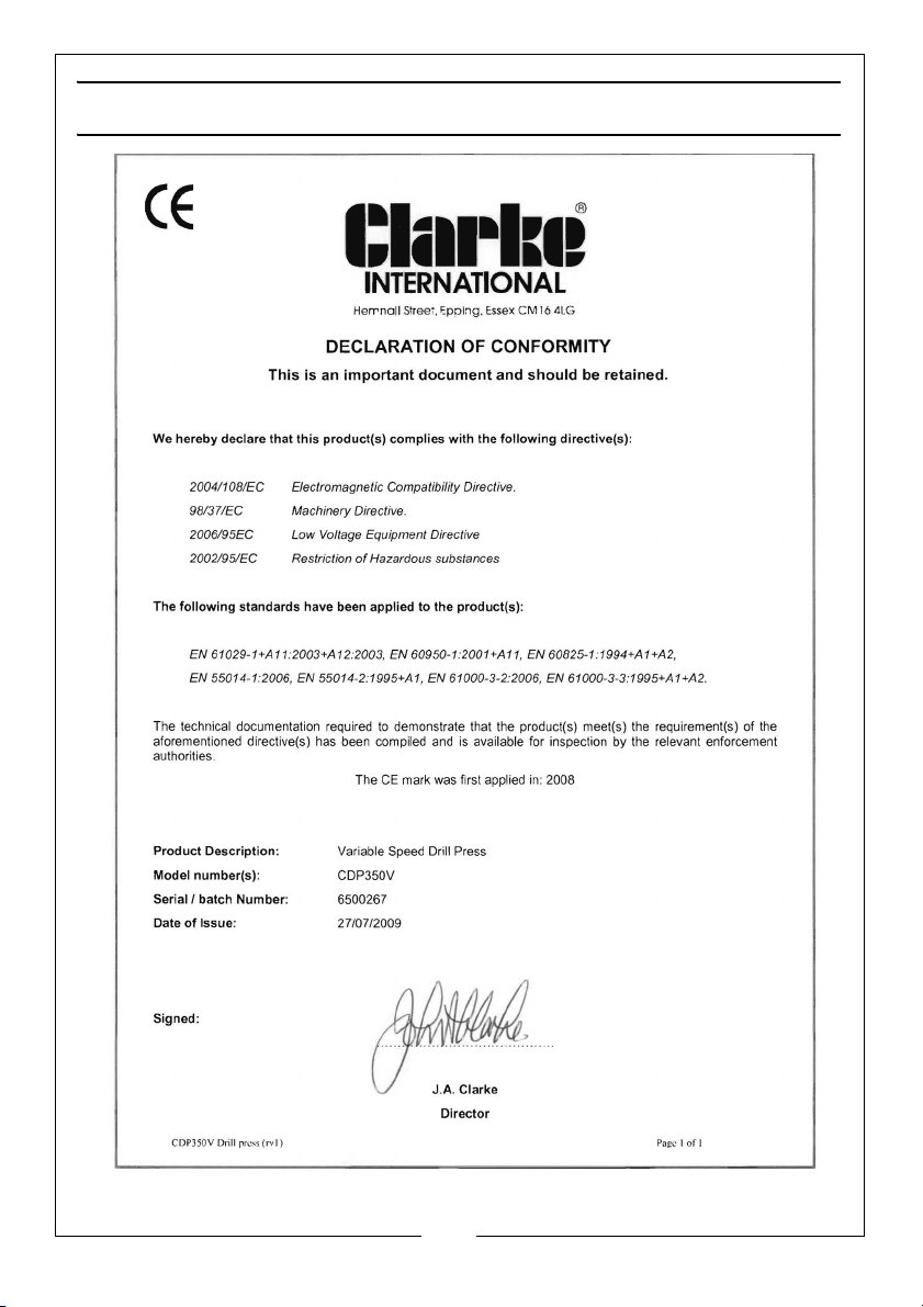
DECLARATION OF CONFORMITY
31
Parts & Service: 020 8988 7400 / E-mail: [email protected] or [email protected]
Page 32

 Loading...