

Page 1
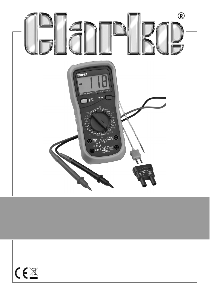
DIGITAL MULTIMETER
MODEL NO: CDM45C
PART NO: 4501155
OPERATING INSTRUCTIONS
ORIGINAL INSTRUCTIONS GC0119 iss 2
Page 2
INTRODUCTION
Thank you for purchasing this CLARKE product.
Before attempting to use this product, please read this manual thoroughly and
follow the instructions carefully. In doing so you will ensure the safety of yourself
and that of others around you, and you can look forward to your purchase
giving you long and satisfactory service.
GUARANTEE
This product is guaranteed against faulty manufacture for a period of 12
months from the date of purchase. Please keep your receipt which will be
required as proof of purchase.
This guarantee is invalid if the product is found to have been abused or
tampered with in any way, or not used for the purpose for which it was
intended.
Faulty goods should be returned to their place of purchase, no product can
be returned to us without prior permission.
This guarantee does not effect your statutory rights.
ENVIRONMENTAL RECYCLING POLICY
Through purchase of this product, the customer is taking on the
obligation to deal with the WEEE in accordance with the WEEE
regulations in relation to the treatment, recycling & recovery and
environmentally sound disposal of the WEEE.
In effect, this means that this product must not be disposed of with general
household waste. It must be disposed of according to the laws governing
Waste Electrical and Electronic Equipment (WEEE) at a recognised disposal
facility.
2
Parts & Service: 020 8988 7400 / E-mail: [email protected] or [email protected]
Page 3

SAFETY INFORMATION
WARNING: TAKE CARE WHEN USING THIS METER. IMPROPER USE CAN
RESULT IN ELECTRIC SHOCK OR DAMAGE TO THE METER. TAKE ALL
NORMAL SAFETY PRECAUTIONS AND FOLLOW THE SAFEGUARDS
SUGGESTED IN THIS MANUAL.
BEFORE USE
1. When using the meter, the user must observe all normal safety rules
concerning:
• General protection against electric shock.
• Protection of the meter against misuse.
2. When the meter is delivered, confirm it has not been damaged in transit.
3. The test leads must be kept in good condition. Before using, check that the
insulation on the test leads has not been damaged or any wire exposed.
4. Use only the test leads supplied to ensure operational safety. If necessary,
they must be replaced with test leads of the same model or class.
DURING USE
1. Never take measurements that exceed the maximum values for this meter.
2. Do not touch the metal probes of the test leads when the meter is
connected to the circuit being measured.
3. Keep your fingers behind the probe barriers when taking measurements.
4. Do not take voltage measurements if you suspect the value exceeds 600V.
5. If the appropriate value range is unknown, select the highest range on the
scale.
6. Disconnect the test leads from the circuit under test before turning the
rotary function selector.
7. Do not measure the resistance, diode or continuity of live circuits.
8. Do not connect the meter to any voltage source while the rotary selector is
in the Current, Resistance, Diode or Continuity range.
9. Do not use the meter near explosive gases or steam.
10. Stop using the meter if any abnormalities or faults are observed.
11. Do not use the meter unless its rear case and battery cover is correctly and
securely fastened.
3
Parts & Service: 020 8988 7400 / E-mail: [email protected] or [email protected]
Page 4
12. Do not store or use the meter in areas exposed to direct sunlight, at high
temperature or with high relative humidity.
13. To avoid false readings, replace the batteries as soon as the Low Battery
indicator appears.
14. Before use, verify the meter operation by measuring a known voltage.
15. Never touch exposed wiring, connections or any live circuit while taking
any measurements.
16. Keep your body isolated from ground by using dry clothing, rubber shoes,
rubber mats or any approved insulating material.
SPECIFICATIONS
Product dimensions: (L x W x H) 195 x 95 x 52 mm
Weight (inc battery) 425 g
Test leads length (inc probes) 990 mm
Max voltage between input & earth 600V
Fuses F1 400mA/600V, F2 10A/600V
Power PP3 type 9V battery
Maximum display value 1999
Over-range indication “1”
Polarity display “-” for negative polarity
Detects and measures voltages DCV 200m/2/20/200 ± 0.5%, 600 ± 0.8%
ACV 2/20/200 ± 0.8%, 600 ±1.2%
Detects and measures resistance Ohm 200Ω ± 0.8%,2k/20k/200k, 2M ±
8%, 20M ± 1%, 200M ± 6%
Detects and measures current DCA2m, 20m ± 8%, 200m± 1.5%, 10± 2%
ACA 20m ± 1%, 200m ± 1.8%, 10± 3%
Detects and measures frequency Hz 20k ± 2%
Detects and measures
capacitance
Detects and measures temperature C° -20 to 0 ± 5%, 1-400 ± 2%, 401-1000 ±
Operating temperature
Storage temperature
Auto power-off time 20 min
F 2n, 20n, 200n, 2
2%
°C
0-40
0°C to 60°C
µ ± 4%,100µ ± 6%
4
Parts & Service: 020 8988 7400 / E-mail: [email protected] or [email protected]
Page 5
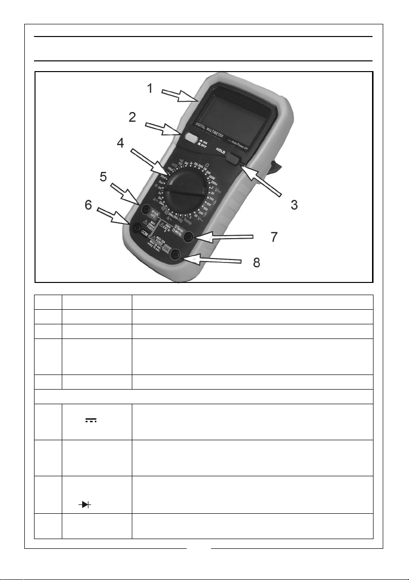
FEATURES OF THE METER
Feature Description/Use
1 Display Digital LCD
2 Power Button Power ON/OFF
3 Data Hold
Button
4 Rotary Switch Selects different functions and range.
The four input sockets are used as follows:
5
mA hFE
6
COM
7
VTemp
Ω Hz
8 10A Positive input for 10A circuit (connected using red test
Press the HOLD button. The LCD will hold the last
reading measured and display the ‘H’ symbol. When
the button is released, the meter will return to normal.
Positive input socket for current, mA, capacitance
and diode tests (connected via red test probe or used
as a dedicated multifunction test socket).
All common inputs to be measured are connected
with via the black test probe. Also used as a
dedicated multifunction test socket.
Positive input socket for voltage, resistance,
frequency, diode, buzzer and temperature tests
(connected using red test probe).
probe).
5
Parts & Service: 020 8988 7400 / E-mail: [email protected] or [email protected]
Page 6
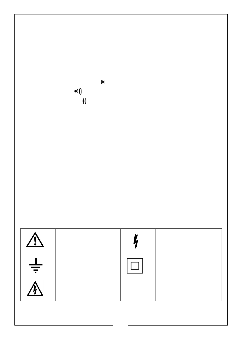
MEASUREMENT FEATURES OF THIS METER
• Alternating voltage measurement:- V~
• Direct voltage measurement:- V=
• Alternating current measurement:- A=
• Direct current measurement:- A=
• Resistance measurement:-
•Diode measurement:-
• Continuity:-
• Capacitance:-
• Frequency measurement:-Hz
• Temperature:- Temp
• Transistor Gain:- hFE
Ω
ITEMS SUPPLIED
• Multi-meter c/w polymer holder and fold-out stand
• Pair of test lead/probes (1 red/1 black)
• 9-volt battery
• Type K fine wire thermocouple
• HFE temperature measurement connector adaptor
SAFETY SYMBOLS
Please read all of the safety and operating instructions carefully before using
this product. The following safety symbols may be found on the product.
General hazard
warning
High voltage
Earth Class II wiring without
earth conductor.
Possibility of high
voltage
6
Parts & Service: 020 8988 7400 / E-mail: [email protected] or [email protected]
Page 7
OPERATION
Before taking the measurement of voltage with the probe, make sure there is
no electronic device connected to the test socket of the instrument.
PREPARATION
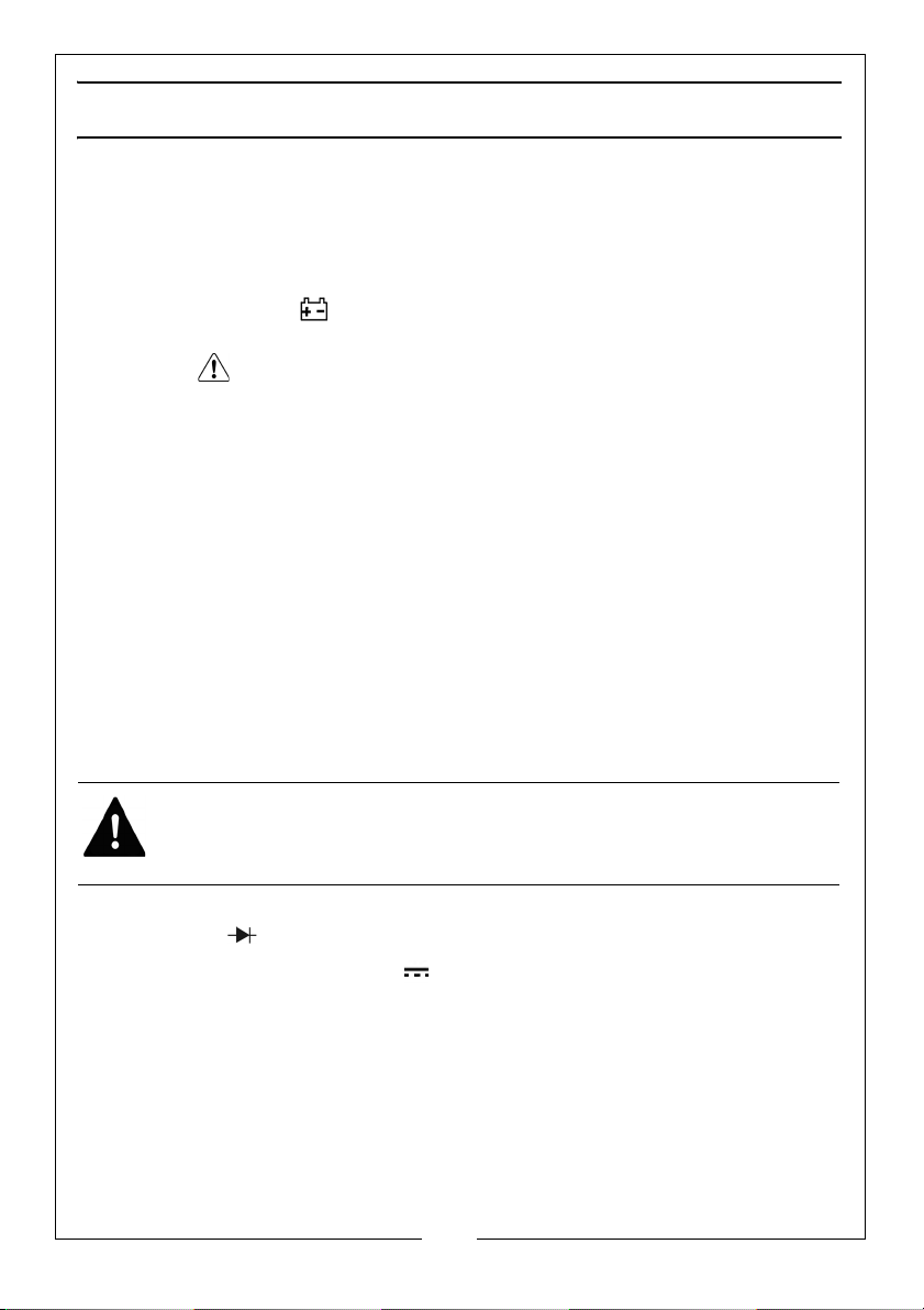
1. Switch on the power by turning the rotary switch. If the battery voltage is
lower than 7V, the symbol will appear and the battery should be
replaced.
• The " " symbol next to the input lead shows that the input voltage or
current should not exceed the specified value in order to protect the
internal circuit from damage.
2. Turn the rotary switch to the required function and range to be measured.
3. Choose the highest range when the value to be measured is unknown.
• When making a connection, connect the black common test lead first
and then the positive red test lead.
4. Remove the positive test lead first when disconnecting.
READING HOLD
1. Press “HOLD” button to hold the readings of current measurement.
2. Press the “HOLD” button again to release the hold.
DC/AC VOLTAGE MEASUREMENT
WARNING: USE CAUTION WHEN MEASURING HIGH VOLTAGE CIRCUITS TO
AVOID ELECTRICAL SHOCK AND INJURY. DO NOT TEST VOLTAGES HIGHER
THAN 600V DC/600V AC.
1. Plug the black test lead into the “COM” jack and the red test lead into the
"VTemp
2. Set the rotary switch to the "V " position for DC measurement and "V~" for
AC measurement and at the proper range.
3. Connect the test leads to the voltage source or load for measurement.
4. Read the value on the main indicator of the LCD. The polarity symbol
denotes the polarity of the end connected by the red test lead.
NOTE: At small voltage ranges, unsteady readings will appear before
Parts & Service: 020 8988 7400 / E-mail: [email protected] or [email protected]
Ω Hz" jack.
the test leads make contact with the circuit. This is normal since
the meter is highly sensitive. When the tes t leads a re
conne cte d to the circuit, the true reading will be shown.
7
Page 8
When “l “is shown on the LCD, it means the measurement has exceeded
the allowable range and a higher range should be selected.
When the scale of the value to be measured is unknown, select the
highest range first and lower the range accordingly.
DC/AC CURRENT MEASUREMENT
WARNING: USE CAUTION WHEN MEASURING HIGH VOLTAGE CIRCUITS TO
AVOID ELECTRICAL SHOCK AND INJURY. DO NOT TEST VOLTAGES HIGHER
THAN 600V DC/AC.
TO AVOID ELECTRICAL SHOCK AND INJURY POWER OFF THE CIRCUIT AND
DISCHARGE THE CAPACITANCE BEFORE MEASURING CURRENT
1. Plug the black test lead into the “COM” jack.
2. When the current to be measured is under 200mA, plug the red test
lead into the “mA” jack; when the current to be measured is over
200mA but under 10A, plug the red test lead into the “10A” jack.
3. Set the rotary switch to the “A " position for DC measurement and
"A~" for AC measurement and at the proper range.
4. Connect the test leads to the circuit.
5. Read the value on the display.
•The polarity symbol denotes the polarity of the red test lead.
NOTE: When ‘1’ is shown on the LCD, it means the me asu rement has
exceeded the allowable range; a higher range should be
selected.
NOTE: When the scale of the value to be measured is unknown, select
the highest range first and then lower the range accordingly.
NOTE: " " indicates the maximum current of the mA jack is 200mA and
the maximum current of the 10A jack is 10A. At either jack, current
exceeding the limit will blow the fuse.
RESISTANCE MEASUREMENT
WARNING: TO AVOID ELECTRICAL SHOCK AND INJURY POWER OFF THE
CIRCUIT AND DISCHARGE THE CAPACITANCE BEFORE MEASURING
RESISTANCE.
1. Plug the black test lead into the "COM" jack and the red test lead into
the "VTemp
2. Set the rotary switch to the “
3. Connect the test leads to the ends of the resistor or circuit.
Parts & Service: 020 8988 7400 / E-mail: [email protected] or [email protected]
Ω Hz" jack.
Ω " position and at the proper range.
8
Page 9
4. Read the value on the LCD.
NOTE: When the input is open, "1 " is displayed on the LCD to indicate
overload. For measuring resistance above 1M
seconds to get a steady reading. This is normal for high resistance
measurement.
Ω, it may take a few
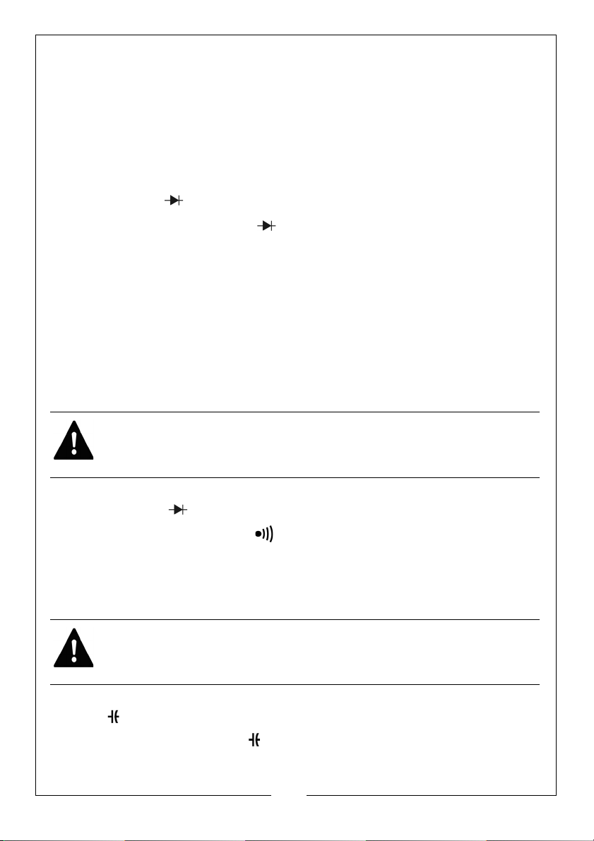
DIODE
1. Plug the black test lead into the "COM" jack and the red test lead into
the "VTemp
2. Set the rotary switch to the " " position.
3. Connect the red test lead to the anode and the black test lead to
the cathode of the diode for testing.
4. Read the value on the LCD.
NOTE: The meter will show approximate forward voltage drop of
NOTE: When the test leads are reversed or opened, '1' will appear
Ω KHz" jack.
the diode.
on the LCD.
CONTINUITY
WARNING: TO AVOID ELECTRICAL SHOCK AND INJURY POWER OFF THE
CIRCUIT AND DISCHARGE THE CAPACITANCE BEFORE TESTING
CONTINUITY.
1. Plug the black test lead into the "COM" jack and the red test lead into
the "VTemp
2. Set the rotary switch to the " " position.
3. Connect the test leads to two ends of the circuit. If resistance of the
circuit is less than 50Ω, the bui lt- in buzzer will sound.
Ω Hz" jack.
CAPACITANCE
WARNING: TO AVOID ELECTRICAL SHOCK AND INJURY POWER OFF THE
CIRCUIT AND DISCHARGE THE CAPACITANCE BEFORE TESTING
CAPACITANCE.
1. Plug the black test lead into the "COM" jack and the red test lead into the
"hFE mA" jack.
2. Set the rotary switch to the position and at the proper range.
9
Parts & Service: 020 8988 7400 / E-mail: [email protected] or [email protected]
Page 10
3. Connect the test leads to two ends of the circuit/ capacitor and read
the value on the LCD.
FREQUENCY MEASUREMENT
1. Plug the black test lead into the "COM" jack and the red test lead into the
“VTemp
2. Set the rotary switch to the "Hz" position.
3. Connect test leads to the two ends of the circuit for measurement.
4. Read the value on the LCD.
Ω Hz" jack.
TEMPERATURE
WARNING: TO AVOID ELECTRICAL SHOCKAND INJURY DO NOT MEASURE
THE SURFACE OF AND OBJECT WITH AN ELCTRICAL POTENTIAL HIGHER
THAN 60V DC/ 24V AC
1. Plug the red end of the K-type thermocouple into the the
"VTemp
2. Set the rotary switch to the "Temp" position.
3. Touch the surface of the object or area with the temperature sensor for
measurement.
4. Read measured value from the LCD.
Ω Hz" jack and the black end intothe "COM" jack.
TRANSISTOR GAIN
WARNING: TO AVOID ELECTRICAL SHOCK AND INJURY DO NOT TEST WITH
VOLTAGES HIGHER THAN 250V DC/AC.
1. Plug the multi-function socket with the "IN" end in the "hFE mA" jack and
the "COM" end in the "COM" jack.
2. Set the rotary switch to the "hFE" position and at the proper range.
3. Determine if the transistor to be tested is either and NPN or PNP type, then
insert the three pins of the transistor into the corresponding holes of the
multifunction socket.
4. Read the approximate transistor gain on the LCD.
10
Parts & Service: 020 8988 7400 / E-mail: [email protected] or [email protected]
Page 11
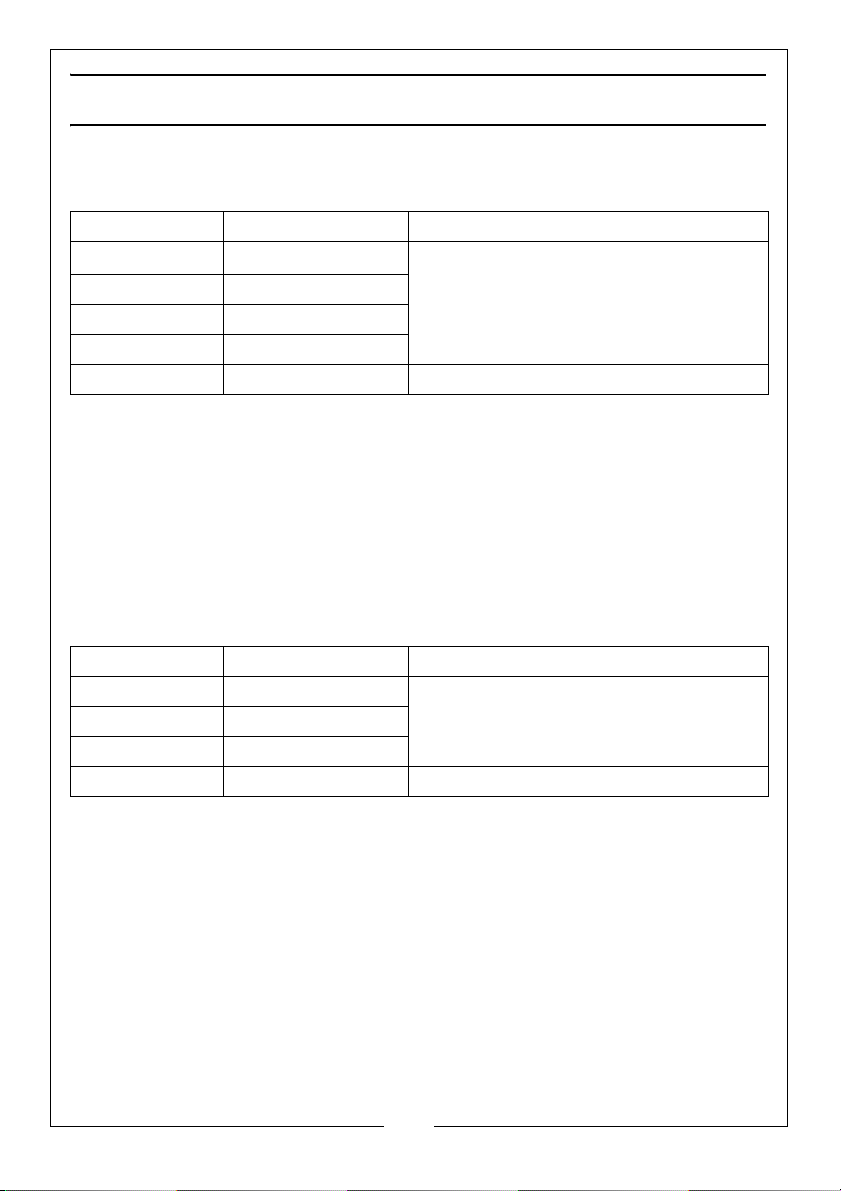
TECHNICAL SPECIFICATIONS
DC VOLTAGE
Range Resolution Accuracy
200mV
2V 1mV
20V 10mV
200V 100mV
600V 1V ± 0.8% of reading, + 2 digits
• Max input voltage: 250V DC at 200mV range, 600V DC elsewhere.
0.1
µV
± 0.5% of reading, + 2 digits
• Input impedance: 10MΩ
NOTE: At low voltage ranges, unsteady readings will appear before the
test leads make contact with the circuit. This is normal since the
meter is highly sensitive. When the test leads connect to the
circuit, the true reading will be shown.
AC VOLTAGE
Range Resolution Accuracy
2V 1mV
20V 10mV
200V 100mV
600V 1V ± 1.2% of reading, + 3 digits
• Max input voltage: 250V AC at 200mV range, 600V AC elsewhere.
• Input impedance: 10MΩ
• Frequency response: 200Hz at 600V range, 40-400Hz
• Response: Average (RMS of sine wave)
NOTE: At low voltage ranges, unsteady readings will appear before the
test leads make contact with the circuit. This is normal since the
meter is highly sensitive. When the test leads connect to the
circuit, the true reading will be shown.
.
± 0.8% of reading, + 3 digits
11
Parts & Service: 020 8988 7400 / E-mail: [email protected] or [email protected]
Page 12
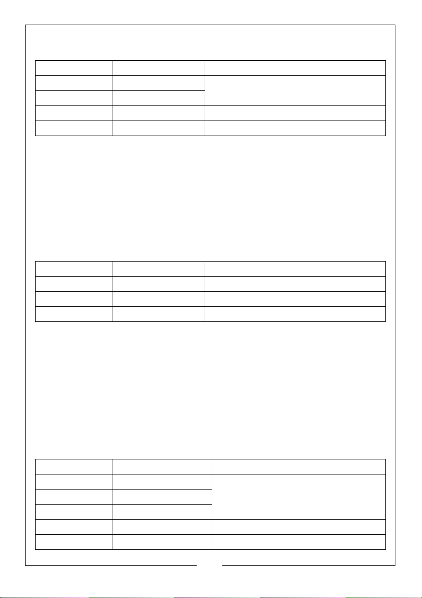
DIRECT CURRENT
Range Resolution Accuracy
2mA 1µA
20mA 10µA
± 0.8% of reading, +1 digits
200mA 100µA ± 1.5% of reading, +1 digits
10A 10mA ± 2% of reading, + 5 digits
• Overload protection: F1 400mA/600V Fuse F2 10A/600V
• 10A range: F2, 10A/600V fuse (quick acting).
• Max input current:
• mA jack (mA range): 200 mA
• 10A jack: 10A
AC CURRENT
Range Resolution Accuracy
20mA 10µA ± 1% of reading, + 5 digits
200mA 100µA ± 1.8% of reading, + 5 digits
10A 10mA ± 3% of reading, + 7 digits
• Overload protection: mA ranges: reset table fuse F1, 400mA/600V dc
• 10A range:F2, 10 A/600V fuse
• Max input current: mA jack (mA range) 200mA
• 10A jack: 10A
• Frequency range: 40Hz to 400Hz
• Display: Average (effective value of sine wave)
CAPACITANCE
Range Resolution Accuracy
2nF 1µF
20nF 10µF
± 0.4% of reading, ±3 digits
200nF 0.1µF
20µF 1µF ± 0.4% of reading, ±2 digits
100µF 100µF ± 6.0% of reading, +10digits
12
Parts & Service: 020 8988 7400 / E-mail: [email protected] or [email protected]
Page 13
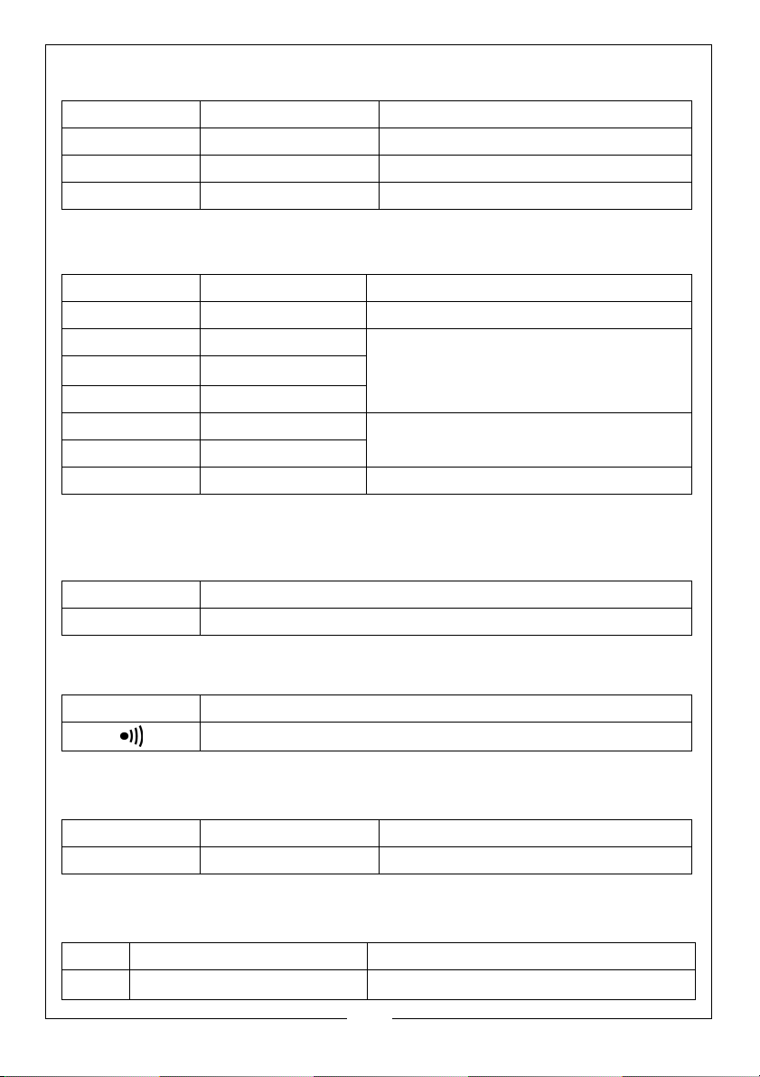
TEMPERATURE
Range Resolution Accuracy
-20C°- 0C° 1C° ± 5% of reading, + 4 digits
1C°- 400C° 1C° ± 2% of reading, + 3 digits
40C°- 1000C° 1C° ± 2% of reading, + 5 digits
RESISTANCE
Range Resolution Accuracy
200Ω 0.1Ω ± 0.8% of reading, +3 digits
2kΩ 1Ω
20kΩ
200kΩ 100Ω
2MΩ 1kΩ
20MΩ 10kΩ
200MΩ 100kΩ ± 6.0% of reading, +10 digits
10Ω
± 0.8% of reading, +2 digits
± 1.0% of reading, + 2 digits
• Overload protection: 250V DC/AC Open circuit voltage:
DIODE TEST
Resolution Function
1mV Displaying approximate forward voltage of diode
CONTINUITY TEST
Function
Built-in buzzer will sound if resistance is lower than 50
FREQUENCY
Range Resolution Accuracy
20kHz 10 Hz ± 2% of reading, ± 5 digits
TRANSISTOR
Range Resolution Accuracy
hFE 1hFE approximation (0-1000)
Parts & Service: 020 8988 7400 / E-mail: [email protected] or [email protected]
Base current 10
13
µA Vce is about DC2.8V
≈ DC 2.8V.
Ω
Page 14
MAINTENANCE
GENERAL CARE
WARNING: BEFORE REMOVING THE REAR COVER, DISCONNECT THE
PROBES FROM THE CIRCUIT TO BE MEASURED. ENSURE THE COVER IS
TIGHTLY SECURED BEFORE USING THE INSTRUMENT.
Never use the meter unless the rear cover is secure.
Clean the housing with a damp cloth dipped in a little detergent but never
chemical solution.
In case of any abnormality, stop using the meter and send it for repair.
REPLACING THE BATTERY
1. Turn off the meter.
2. Unscrew battery cover and remove.
3. Remove the battery and replace with a new one.
4. Clip the battery compartment to the casing and tighten the screw.
REPLACING FUSES
Fuses rarely need replacement. Almost all fuse blows are the result of operator
error. Fuses should be replaced by the Clarke Service Department with the
type(s) stated on page 4.
TEST LEAD REPLACEMENT
WARNING: REPLACE THE TEST LEADS WITH IDENTICAL OR COMPATIBLE
LEADS. LEAD SPEC: 1000V 10A.
Replace the leads if they become damaged.
14
Parts & Service: 020 8988 7400 / E-mail: [email protected] or [email protected]
Page 15
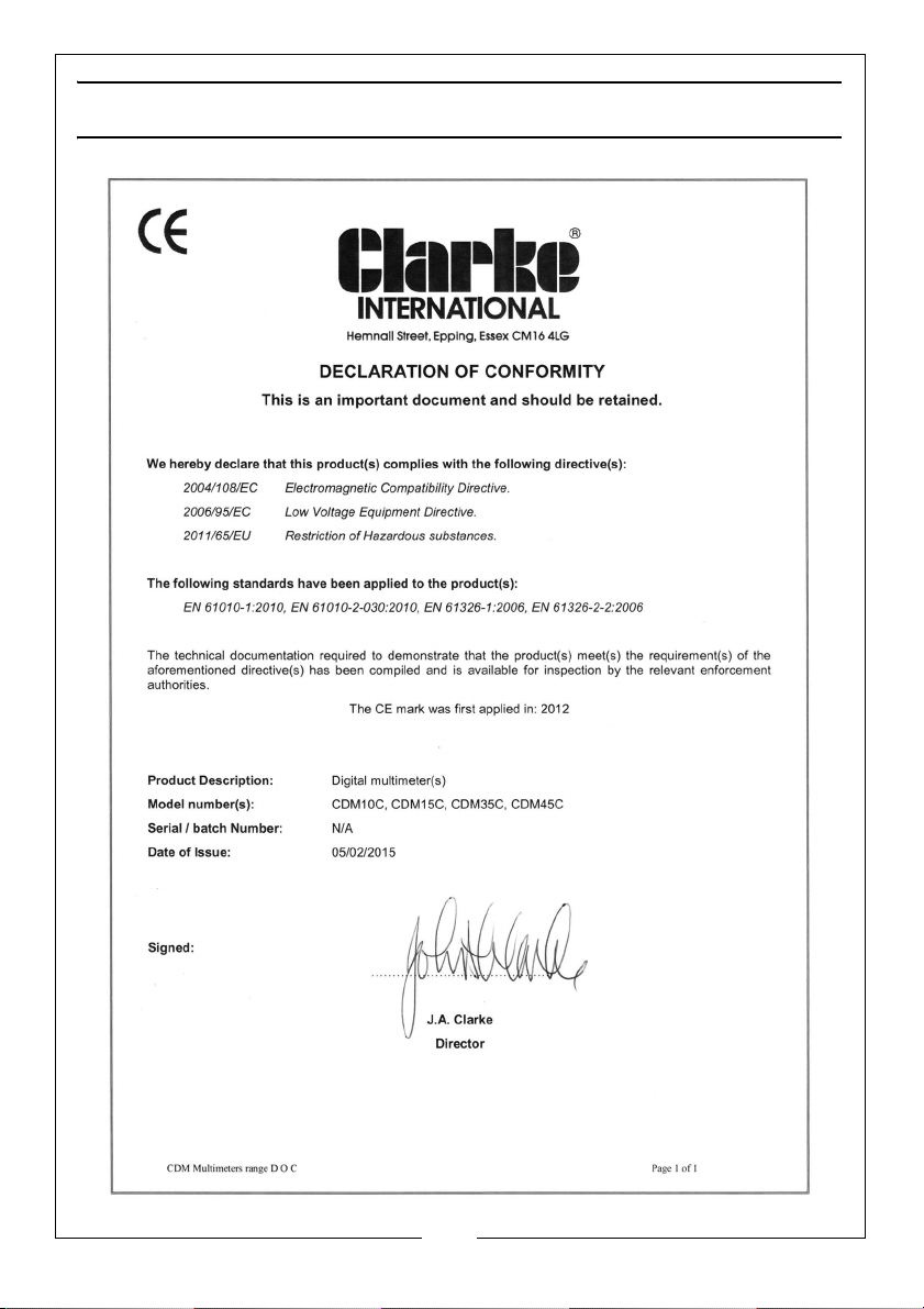
DECLARATION OF CONFORMITY
15
Parts & Service: 020 8988 7400 / E-mail: [email protected] or [email protected]
Page 16

 Loading...