


4½” (115mm)
ANGLE GRINDER
Model No. CAG115C
OPERATING & MAINTENANCE
INSTRUCTIONS
0398

Thank you for selecting this CLARKE 115mm (4½”) Angle Grinder, designed for DIY
and light workshop use only.
Before attempting to use the tool, please read this leaflet thoroughly and follow
the instructions carefully. In doing so you will ensure the safety of y ourself and that
of others around you, and you can look forward to the Angle Grinder giving you
long and satisfactory service.
GUARANTEE
This product is guaranteed against faulty manufacture for a period of 12 months
from the date of purchase. Please keep your r eceipt therefore, as proof of purchase.
This guarantee is inv alid if the product is f ound to have been abused or tampered
with in any way, or not used for the purpose for which it was intended.
Faulty goods should be returned to their place of purchase, no product can be
returned to us without prior permission. This guar antee does not eff ect your statutory
right
s.
CONTENTS
Safety Precautions.....................................................................2
Additional Precautions for Angle Grinders .............................4
Electrical Connections..............................................................5
Features ......................................................................................5
Assembly.....................................................................................6
Operation ...................................................................................7
Maintenance .............................................................................7
Specifications.............................................................................7
Troubleshootiing.........................................................................8
Spare Parts..................................................................................9
SAFETY PRECAUTIONS
GENERAL SAFETY PRECAUTIONS FOR POWER TOOLS
WARNING:
As with all machinery, there are certain hazards involved with their operation and
use. Exercising respect and caution will considerably lessen the risk of personal
injury. However, if normal safety precautions are overlooked or ignor ed, personal
injury to the operator or damage to property, may result.
1. READ and BECOME FAMILIAR with the entire operating manual. Learn the
tools’ applications, limitations and the specif ic potential hazards peculiar
to it.
2

2. ALWAYS ensure that ADEQUATE LIGHTING is available. A minim um intensity of
300 lux should be provided. Ensure that lighting is placed so that you will not
be working in your own shadow.
3. CHECK for DAMAGE. Before using the tool, any damaged part should be
checked to ensure that it will operate properly and perform its intended
function. Check for alignment of moving parts, breakage of parts, mountings
and any other condition that may affect the tools’ operation. Any damage
should be properly repaired or the part replaced. If in doubt, DO NOT USE the
tool. Consult your local dealer.
4. DISCONNECT the TOOL from the power supply before servicing and when
changing accessories.
5. ALW AYS WEAR SAFETY GOGGLES manuf actured to the latest European Safety
Standards. Ev eryday eyeglasses do not have impact resistant lenses, they are
NOT safety glasses.
6. KEEP WORK AREA CLEAN. Cluttered areas and benches invite accidents.
7. DON’T FORCE the tool. It will do a better and safer job at the rate for which it
was designed.
8. ALWAYS use a face or dust mask if operation is particularly dusty.
9. DRUGS, ALCOHOL, MEDIC ATION. Do not operate tool while under the influence
of drugs, alcohol or any medication.
10. USE RECOMMENDED ACCESSORIES. The use of improper accessories could
be hazardous.
11. NEVER LEAVE THE TOOL RUNNING UNATTENDED . Turn power OFF. Do not leave
the tool until it comes to a complete stop.
12. AVOID DANGEROUS ENVIRONMENT. Don’t use power tools in damp or wet
locations or expose them to rain. Keep your work area well illuminated.
DO NOT USE in explosive atmosphere (around paint, flammable liquids etc.).
13. KEEP CHILDREN A W AY. All visitors should be kept a safe distance from the w ork
area, especially whilst operating the tool.
14. MAINTAIN TOOL IN TOP CONDITION. Keep tools clean for the best and safest
performance. Follow maintenance instructions.
15. DON’T OVERREACH. Keep your proper footing/balance at all times. For best
footing wear rubber soled footwear. Keep floor clear of oil, scrap wood, etc.
16. WEAR PROPER APP AREL. Loose clothing or jewellery may get caught in mo ving
parts. Wear protective hair covering to contain long hair.
17. HANDLE WITH EXTREME CARE Do Not carry the tool by its’ electric cable, or
yank the cable to disconnect it from the power supply .
18. AVOID ACCIDENTAL STARTING. Ensure the switch is OFF before plugging in to
mains.
19. BE AWARE that accidents are caused by carelessness due to familiarity.
ALWAYS concentrate on the job in hand, no matter how trivial it may seem.
3

ADDITIONAL PRECAUTIONS FOR ANGLE GRINDERS
1. It is strongly advised that you wear ear pr otectors/defenders as the noise level
during operation, depending upon the work being carried out, can exceed
safe working levels.
2. Always wear a good pair of industrial glov es to avoid potential injury from
sparks and debris.
3. Do not use the tool if the electric cable, plug or motor is in poor condition.
4. Keep the mains cable well away from the tool and ensure an adequate
electrical supply is close at hand so that the operation is not restricted by the
length of the cable.
5. Switch the tool OFF immediately the task is completed.
6. Never allow the ventilation slots in the tool to become blocked.
7. Do not attempt any electrical repair yourself. Consult a qualified electrician,
or our Service Dep’t on 0181 556 4443.
8. DO NOT cut through walls or cavities before checking for hidden electrical
wires or water pipes etc.
9. Ensure the grinding wheel or cutting disc is fully tightened before use.
10. Do not use the tool in a confined space which may limit body movement.
11. Ensure the wheel/disc is not touching the work when switching ON.
12. Use only wheels/discs having a maximum operating speed of at least
11,000RPM.
13. Check the disk carefully for cracks or damage before operation. Replace
cracked or damaged wheels/discs immediately.
14. Take care not to damage the spindle or wheel flanges as damage to these
parts could result in wheel/disc breakage.
15. ALWAYS hold the tool firmly in BOTH hands.
16. Before using the tool on an actual w orkpiece, allow it to run briefly, checking
for vibration which could indicate poor balance or installation of the wheel/
disc.
17. Use only wheels/discs designed for their specific function. DO NOT use cutting
discs for grinding metal, or metal grinding wheels for cutting masonry.
O
18. Beware of flying sparks, hold the grinder at an angle of 15 - 30
surface.
19. NEVER use excessive force. It should only be necessary to use a little more
than the weight of the tool. If the rotational speed drops abnormally, reduce
pressure immediately. Forcing the tool and excessive pressure can cause
dangerous disc breakage and/or damage to the tool.
20. NEVER use the tool with the guard removed. If the guard becomes damaged,
it should be replaced
to the workpiece
Additionally, ALWAYS keep these instructions in a safe place for future reference.
4

ELECTRICAL CONNECTIONS
This product is provided with a 13 amp, 230 volt (50Hz), BS 1363 plug, for
connection to a standard, domestic electrical supply. Should the plug need
changing at any time, ensure that a plug of identical specification is used.
IMPORTANT:
This appliance is of Double Insulation construction and no earth conductor is therefore provided. The two wires in the mains lead should be wired up in
accordance with the following colour code:
Blue — Neutral
Brown — Live
Connect the BROWN coloured cord to the plug terminal marked a letter “L”
Connect the BLUE coloured cord to the plug terminal marked a letter “N”
If this appliance is fitted with a plug which is moulded on to the electric cable (i.e.
non-rewireable) please note:
1. The plug must be thrown away if it is cut from the electric cable. There is a
danger of electric shock if it is subsequently inserted into a socket outlet.
2. Never use the plug without the fuse cover fitted.
3. Should you wish to replace a detachable fuse carrier, ensure that the correct
replacement is used (as indicated by marking or colour code).
4. Replacement fuse covers can be obtained from your local dealer or most
electrical stockists.
FUSE RATING
The fuse in the plug must be replaced with one of the same rating (13 amps) and
this replacement must be approved to BS1362.
If in doubt, consult a qualified electrician. Do not attempt any electrical repairs
yourself.
CABLE EXTENSION.
Do not use an extension longer than 10 metres and one where the conductors, are
less than 1.5mm2.
FEATURES (Ref. Fig 1 page 6)
1. Safety ON/OFF Switch
To operate the safety ON/OFF switch, press down on the ‘I’ mark (ON), and slide
the switch forwar d until it clicks and loc ks into place. To release the switch (Switch
OFF), press down on the ‘O’ (OFF) mark and the switch will snap back to the OFF
position.
2. Spindle Lock Button.
When pressed, this button, located on top of the head, is used to lock the spindle
when attempting to unscrew and remove the outer f lange (using the special tool
provided), in order to mount or change the grinding wheel or cutting disc.
5

WARNING:
NEVER press the spindle lock button when starting the tool, and
NEVER press the button when the tool is operating.
DO NOT pr ess button until the wheel/disc has stopped completely
3. Quick Change Guard.
The guard is capable of rotating about
its axis. Grasp it firmly and turn to the
desired position before connecting the
tool to the mains supply and switching
ON.
You should always turn the guard so as
to provide the greatest amount of
protection for the hand gr ipping the
hand grip, without impeding the work
being carried out.
ASSEMBLY
1. Mounting the Grinding Wheel/Cutting Disc.
1.1 Unscrew and remov e the outer f lange. If it
is tight, lock the spindle by pressing the
Spindle Lock button and use the tool
supplied to turn the flange to break the
seal. It may then be screwed off by hand.
1.2 The Grinding wheel supplied is a Depressed
Centre’ type. Mount it as shown in the
diagram. i.e. with the depressed centre
towar ds the motor ,
1.3 Ensuring the wheel sits snugly over the
raised boss on the inner flange, screw on
the outer flange with the centre boss facing inwards.
Tighten the flange using the tool provided, locking the spindle b y pressing
the Spindle Lock button, and taking care to ensure the wheel is still sitting
snugly, centred o ver the f lange bosses. Care should be taken also NOT to
overtighten the outer flange.
Fig 1.
Fig 2.
IMPORTANT :
Fig . 2 shows the set up for a grinding wheel.
When attaching a cutting disk, YOU MUST REVERSE the Outer flange.
2. Hand Grip
A threaded hole, on the left or right hand side of the gear housing, is provided so
that the hand grip may be screwed in, as required, to provide left or right hand
control of the tool.
6
OPERATION
IMPORTANT: DO NOT plug the tool in to the mains, unless you have ensured it is
switched OFF and the guard is set to the desired position.
The hand holding the body will control the ON/OFF switch, whilst the other hand
grasps the hand grip and guides the tool over the workpiece.
Hold the tool firmly but not tightly . Allo w the tool to do the work...DO NOT f orce the
wheel on to the workpiece.
MAINTENANCE
IMPORTANT: Before carrying out any maintenance tasks, ALWAYS disconnect the
tool from the mains electrical supply.
Before Each Use
1. Always inspect the tool before use, and ensure it is in top condition.
2. Ensure all air vents are clear, use compressed air to clean the tool where
possible. (Always wear protective goggles when cleaning with compressed
air).
3. Check the power cable to ensure it is sound and free fr om crac ks, bare wires
etc.
4. Ensure the grinding wheel or cutting disc is perfectly sound, free from cracks
or damage in any way.
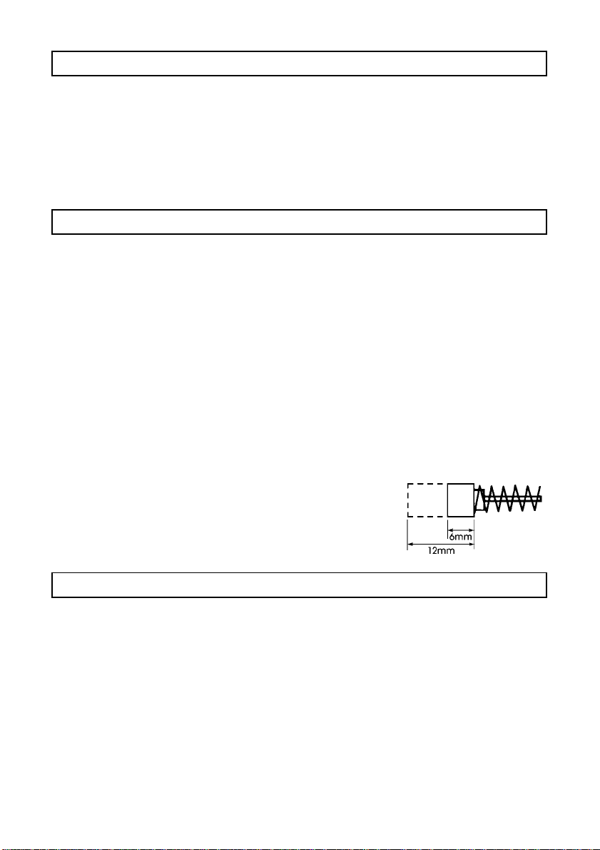
After every 50 hours of use.
Unscrew Carbon Brush Caps, withdraw the Carbon
Brushes and check their condition. The y must be replaced
when they have worn down to 6mm in length. If they are
found to be serviceable, blow the brush holder clean
with compressed air, and replace.
SPECIFICATIONS
Motor ........................................................... 230V~ 50Hz 1ph
Power Rating ............................................... 720Watts
Fuse Rating .................................................. 13Amps
No Load Speed .......................................... 11,000RPM
Wheel/Disc Dia. .......................................... 115mm
Bore .............................................................. 22mm
Weight (Net)................................................ 2.3kg
Part No......................................................... 6470130
7

TROUBLESHOOTING
Problem Possible Cause Remedy
Tool will not operate 1. No Supply 1. Check Supply and rectify
where necessary.
2. Switch is faulty 2. Consult your Clarke dealer
3. Brushes badly worn 3. Check and replace if
necessary
4. Fuse blown 4. Check and replace if
necessary. If condition
persists, consult your dealer
5. Motor faulty 5. Consult your Clarke dealer.
Motor runs but disc 1. Flange nut not tight 1. Tighten flange nut
will not 2. Gear shaft or key 2. Consult your Clarke dealer
broken
Heavy internal 1. Faulty motor 1. Consult your Clarke dealer
Sparking 2. Badly worn Brushes 2. Renew brushes (see p.7)
Motor gets hot 1. Work load too heavy 1. Reduce force applied to tool
2. Low supply voltage 2. Ensure supply voltage is
correct. If extension cable is
used, ensure it is of the
correct value, and is fully
unreeled
Excessive vibration 1. Wheel not mounted 1. Check and rectify
correctly
2. Bearings worn 2. Consult your Clarke dealer
This product conforms with the following directives:
73/23/EEC and 89/336/EEC
8

PARTS DIAGRAM
SPARE PARTS
1. Brush Set Part No. HTSPAG0055
2. Hand Grip HTSPAG0050
3. Guard HTSPAG0070
4. Brush Cap HTSPAG0056
5. Outer Flange HTSPAG0058
6. Inner Flange HTSPAG0057
7. Flange Tool HTSPAG0059
8. Grinding Wheel/Cutting Disc (See below)
The following Grinding Wheels/ Cutting Discs are av ailable from your Clarke dealer .
1. Metal Grinding (DPC) 115mm x 6mm thickness Part No. 6470705
2. Metal Cutting (DPC) 115mm x 3mm thickness 6470775
3. Masonry Cutting (DPC) 115mm x 3mm thickness 6470735
For Spare Parts and Servicing, please contact your nearest dealer, or
CLARKE International, on one of the following numbers.
PARTS - 0181 558 6696 SERVICE - 0181 556 4443
PARTS & SERVICE FAX - 0181 558 3622
Please note that the details and specifications contained herein, are correct at the time of going to print. However,
CLARKE International reserve the right to change specifications at any time without prior notice.
9
 Loading...