

Page 1

2 VMA643
English
Owner’s Manual
Thank you for purchasing this Clarion product.
∗ Please read this Owner’s manual and Installation manual in its entirety before proceeding with wire
connection and installation.
∗ After reading this manual, be sure to keep it in a handy place (e.g., glove compartment).
If you sell the motor vehicle, please leave the manual in it so that the new owner can use it.
∗ Read the contents of the enclosed warranty card and keep it with this manual.
1. This set is for use in DC 12V, negative
ground vehicles. Be sure to consult your
store of purchase or a Clarion-designated
service outlet before installing it on DC 24V
cars.
2. Do not operate the set in ways other than
described in this manual. Doing so may
damage it.
3. For your safety, the driver should not watch
the TV or operate the controls while driving.
Please note that watching and operating the
TV while driving are prohibited by law in
some countries. Also, while driving, keep the
volume to a level at which external sounds
can be heard.
4. Be careful not to run down the car battery
while using the set with the car stopped.
5. Do not disassemble or modify the set. Doing
so may damage it.
6. Keep drinks and water drops from umbrellas
away from the set. Water may damage the
internal circuitry.
1. PRECAUTIONS
7. Do not let lit cigarettes or other hot objects
touch the set. Doing so may damage or
deform the cabinet.
8. Do not let the set become hot. If the
temperature in the car is high or if the set
has been exposed to direct sunlight and is
hot, lower the temperature before using it.
(The LCD panel will work properly within a
temperature range of 0°C to 40°C.)
9. In extremely cold temperatures, the
movement of the picture may be slow and
the picture may be dark, but this is not a
malfunction. The set will work normally once
the temperature increases.
10. Small black and shiny dots inside the liquid
crystal panel are normal for liquid crystal
products.
Contents
1. PRECAUTIONS .............................................................................................................................. 2
2. FEATURE ........................................................................................................................................ 3
3. CAUTIONS ON HANDLING ............................................................................................................ 4
Cleaning .......................................................................................................................................... 4
4. NAMES OF PARTS AND THEIR FUNCTIONS .............................................................................. 5
Display Unit ..................................................................................................................................... 5
5. OPERATIONS ................................................................................................................................. 6
Turning the power ON/OFF ............................................................................................................. 6
Adjusting the volume of the monitor speaker .................................................................................. 6
Changing settings ............................................................................................................................ 6
6. TROBLESHOOTING ....................................................................................................................... 9
7. SPECIFICATIONS ......................................................................................................................... 10
Page 2

VMA643 3
English
Owner’s Manual
WARNING
MONITOR AND TUNER MUST BE INSTALLED AND USED ONLY IN ACCORDANCE WITH
THESE INSTRUCTIONS. FAILURE TO DO SO MAY CAUSE DAMAGE TO THE VEHICLE OR
THE MONITOR, MAY RESULT IN AN ACCIDENT, AND MAY VIOLATE THE LAW. CLARION
DISCLAIMS ANY LIABILITY FOR ANY DAMAGES THAT MAY RESULT FROM A FAILURE TO
INSTALL AND USE THIS UNIT AS STATED IN THESE INSTRUCTIONS.
2. FEATURE
● 6.5" wide-screen color LCD panel
The 6.5" TFT active matrix color LCD panel
delivers striking images.
● Bright, clear screen
The color LCD panel has 336,960 pixels for
superior image resolution.
● Switchable screen size
The display can be switched between five
screen sizes: normal, full-wide, wide, cinema
1 and cinema 2.
● Video input terminal
The display can be used to enjoy video
images even if no TV tuner is connected.
● NAVI input terminal
RGB input terminal
● PAL/NTSC automatic recognition
PAL or NTSC is automatically switched to
match the input signal.
● NAVI remote control compatibility
DVD NAVIGATION NAX943DV can be
operated by remote control.
Page 3

4 VMA643
English
Owner’s Manual
3. CAUTIONS ON HANDLING
•Cleaning the cabinet
Use a soft, dry cloth to gently wipe off dirt.
For tough dirt, apply some neutral detergent
diluted in water to a soft cloth, wipe off the dirt
gently, then wipe again with a dry cloth.
Do not use benzine, paint thinner, car cleaner,
etc., as these substances may damage the
cabinet or cause the paint to peel. Also,
leaving rubber of plastic products in contact
with the cabinet for long periods of time may
cause stains.
•Cleaning the LCD panel
The LCD panel tends to collect dust, so wipe
it off occasionally with a soft, dry cloth.
The surface is easily scratched, so do not rub
it with hard objects.
CAUTION
For a longer service life, be sure to read the following cautions
• Do not disconnect the control box and display unit during use. Also, be sure to turn the
power OFF before disconnecting the display unit.
• Don’t allow any liquids on the set from drinks, umbrellas, etc. Doing so may damage the internal
circuitry.
• Do not disassemble or modify the set in any way. Doing so may result in damage.
• Do not let cigarettes burn the display. Doing so may damage or deform the cabinet.
• If a problem should occur, have the set inspected at your store of purchase.
• Do not hold on the LCD panel when adjusting the angle of the LCD panel. Doing so may damage it.
Precautions on handling of the LCD panel
• Do not leave the monitor on the dashboard with the LCD panel facing upwards. (Range of storage
temperature: –20°C to +80°C)
When the temperature is high or low, chemical changes occur in the LCD panel, resulting in damage
to the monitor.
• Since the LCD panel has been specially processed, fingerprints will remain on the panel and stand
out if you touch the panel. Avoid touching the panel as much as possible. Also avoid pushing the
panel.
• When the temperature becomes low, the picture does not appear or sometimes it takes time to
appear. On occasion, picture motion seems to be different from that at normal temperature and the
picture quality deteriorates. These phenomena are not a malfunction. (Range of operating
temperature: 0°C to +40°C)
• On the panel red dots, blue dots and green dots are found. This is peculiar to the LCD panel and it is
not a malfunction.
[The LCD panel has been designed and manufactured using highly developed precision technology
and has 99.99 % or more effective pixels. However, note that 0.01 % of pixels are defective and
always light.]
Cleaning
Page 4
VMA643 5
English
Owner’s Manual
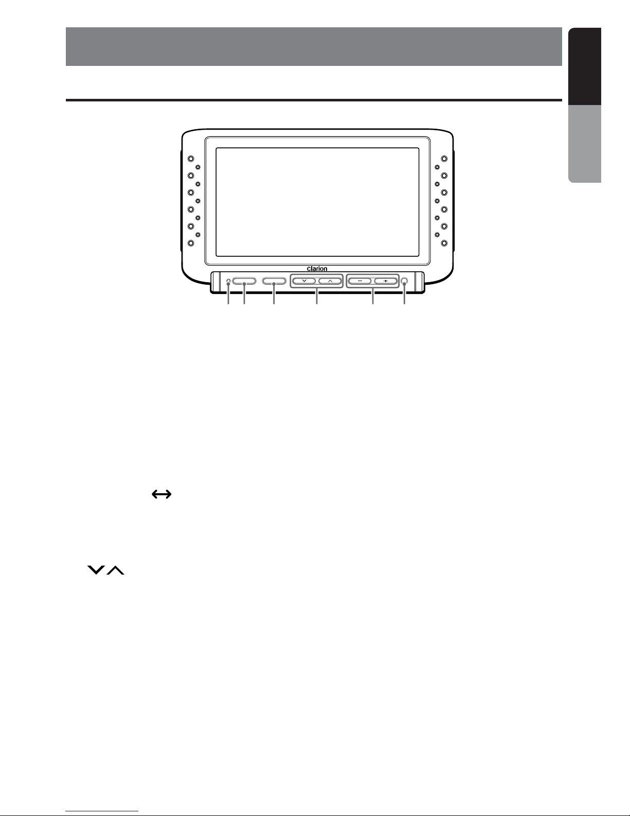
POWER
VISUAL
ADJUST VOLUME
1 2 3 64 5
1 POWER indicator
Lights when the power is on.
2 POWER button
Turns the power ON and OFF.
3 ADJUST/VISUAL button
• Each press of this button toggles between
the screen modes.
NAVI TV
• Holding down this button for about one
second turns the setup screen ON and
OFF.
4 (search) buttons
Selects the setting item in the setup screen.
4.
NAMES OF PARTS AND THEIR FUNCTIONS
Display Unit
5 VOLUME buttons
• Increase or decrease the volume.
• In the setup screen, these buttons become
the item adjustment buttons.
6 Remote control sensor
Receives signals from the NAVI remote
control.
Page 5
6 VMA643
English
Owner’s Manual
5. OPERATIONS
Turning the power ON/
OFF
Press the POWER button.
The power is turned ON/OFF.
Adjusting the volume of
the monitor speaker
Press the – and + sides of the VOLUME button
to adjust the volume.
Note:
• Audio on the monitor speakers becomes
monaural.
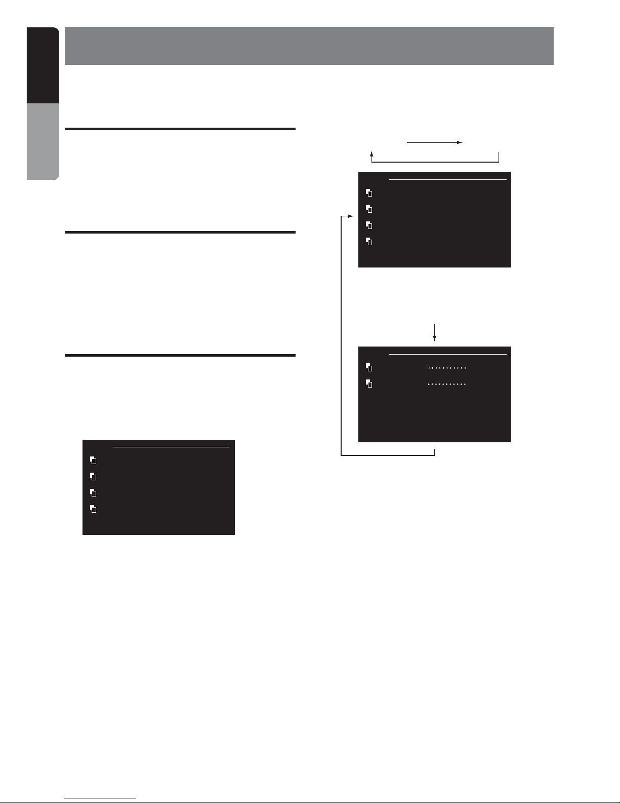
Changing settings
■ Selecting the setting item
1. Hold down the ADJUST/VISUAL button for 1
second or longer to display the setup
screen.
ADJ 1/2
BRIGHT +29
HUE 0
COLOR 0
DIMMER +29
■ Switching the setup screen
Each press of the ADJUST/VISUAL button
switches the setup screen.
ADJ 1/2 ADJ 2/2
ADJ 1/2
BRIGHT +29
HUE 0
COLOR 0
DIMMER +29
ADJ 2/2
WIDE MODE F.WIDE
VISUAL N/P AUTO
■ Adjusting screen quality
About screen quality
The brightness, hue, color density and intensity
of the screen can be adjusted so that you can
view images at the desired screen quality.
• BRIGHT
This item can be adjusted for each of the
NAVI and VTR modes.
• HUE/COLOR
This item can be adjusted only when the
parking break is pulled up when the screen is
in the VTR mode.
* Only “BRIGHT” and “DIMMER”
are displayed in the navigation
screen.
Page 6

VMA643 7
English
Owner’s Manual
■ Switching the screen mode
This unit has five screen modes.
•F.WIDE (full wide mode)
The entire 4:3 image is displayed elongated
uniformly in the horizontal direction.
• CINEMA 1 mode
4:3 images are displayed with the top and
bottom of the image cut off.
• CINEMA 2 mode
Use this mode when sub-titles are cut off from
screen in the Cinema 1 mode.
• NORMAL mode
4:3 images are displayed in the regular
format.
• WIDE mode
4:3 images are displayed with only the left and
right edges of the image elongated in the
horizontal direction.
• The default is “F.WIDE”.
1. As described in “Selecting the setting
item”, display setup screen 2/2.
ADJ 2/2
WIDE MODE F.WIDE
VISUAL N/P AUTO
2. Select the desired screen mode using the
(search) buttons, and select one of
the F.WIDE , CINEMA 1, CINEMA 2,
NORMAL and WIDE modes using the
VOLUME (–, +) buttons.
ADJ 2/2
WIDE MODE F.WIDE
VISUAL N/P CINEMA 1
CINEMA 2
NORMAL
WIDE
3. Hold down the ADJUST/VISUAL button for 1
second or longer to return to the regular
screen.
• When regular 4:3 images that are not wide
images are displayed fully on a wide TV
screen in the F.WIDE mode, part of the
periphery of the image may not be visible
or may appear deformed.
Images can be viewed as originally
intended by the producer in the NORMAL
mode.
Changing settings
• DIMMER
Small light ON/OFF can be set separately for
each of the NAVI and VTR modes.
• The default DIMMER settings are daytime
(illumination OFF) and nighttime
(illumination ON). The default for daytime is
“+29” and for nighttime “0” for both
composite and RGB images.
• HUE is displayed only when the screen
mode is VTR and the video format is NTSC.
1. As described in “Selecting the setting
item”, display setup screen 1/2.
ADJ 1/2
BRIGHT +29
HUE 0
COLOR 0
DIMMER +29
2. Select the brightness, hue, color and
intensity using the (search) buttons,
and adjust the desired item using the
VOLUME (–, +) buttons.
ADJ 1/2
BRIGHT +29
HUE 0
COLOR 0
DIMMER +29
3. Hold down the ADJUST/VISUAL button for 1
second or longer to return to the regular
screen.
Note:
•To store the new settings for items made in the
setup screen to memory, you must hold down the
ADJUST/VISUAL button to return to the regular
screen. If the power or ACC is turned OFF
midway while you are changing settings in the
setup screen, the new settings are not stored to
memory.
Page 7

8 VMA643
English
Owner’s Manual
● How regular 4:3 images are displayed
changes according to the screen mode as
follows
Changing settings
F.WIDE (full wide) mode
CINEMA 1 mode
CINEMA 2 mode
NORMAL mode
WIDE mode
The overall image is elongated
horizontally.
The top and bottom of the image
become out of view.
The top of the image becomes
out of view.
Black stripes appear at the left
and right edges of the image.
Images at the left and right sides of
the screen are elongated horizontally.
■ Switching the video format
Both PAL and NTSC images can be viewed on
this monitor.
• The default is “AUTO”.
Note:
• This monitor does not support SECAM and other
video formats.
1. As described in “Selecting the setting
item”, display setup screen 2/2.
ADJ 2/2
WIDE MODE F.WIDE
VISUAL N/P AUTO
2. Select the desired screen mode using the
(search) buttons, and select one of
AUTO, PAL and NTSC using the VOLUME
(–, +) buttons.
ADJ 2/2
WIDE MODE F.WIDE
VISUAL N/P AUTO
PAL
NTSC
3. Hold down the ADJUST/VISUAL button for 1
second or longer to return to the regular
screen.
• If the state of images is poor when “AUTO”
is selected, a probable cause is that the
video format is being mistakenly
recognized. Select either “PAL” or “NTSC”
as the video format to match the
equipment you are using.
• When “AUTO” is selected, images on the
monitor are sometimes disrupted for about
one second while the image signal that is
input is being recognized.
Page 8

VMA643 9
English
Owner’s Manual
6. TROBLESHOOTING
Please recheck the following point.
Symptom
Screen is dark.
Colors are faint.
Tone is poor.
No color. Screen
drifts.
The image is
displayed in double
or triple.
Spots or stripes
appear in images.
No sound
Cause
Insufficient brightness and
intensity adjustment
Poor operating environment
Car light is turned ON.
Insufficient color adjustment
Wrong video format setting
Poor reception
Radiowave interference
Insufficient volume adjustment
Remedy
Make sure that BRIGHT and DIMMER are correctly
adjusted.
A probable cause is that the temperature inside your
car is 0°C or lower or 60°C or higher. Set the
temperature inside your car to the appropriate
temperature of around 25°C, and then check again.
During nighttime, darken the screen to avoid a
dazzling look. (Even in the daytime, the screen
grows darker if the car light is turned ON.) Adjust the
DIMMER setting.
Make sure that HUE and COLOR are correctly
adjusted.
Check the NTSC/PAL settings. (With some input
images, NTSC/PAL sometimes cannot be
recognized in the “AUTO” mode.)
A probable cause is adverse influence of reflecting
radiowaves in mountainous areas or areas with lots
of buildings. Change the location and orientation,
and then check again.
A probable cause is influence from cars, trains, highvoltage lines, or neon signs. Change the location,
and then check again.
A probable cause is that the volume is set to
minimum. Check the volume level again.
Page 9

10 VMA643
English
Owner’s Manual
7. SPECIFICATIONS
General
Model No.: VMA643
Type : Liquid crystal color monitor unit
Power supply voltage :
DC 13.2V (exclusively for a 12V car)
Power consumption :
12 W (0.05 W at stand-by)
Operating temperature range : 0°C to +40°C
Storage temperature range : –20°C to +80°C
Control Box
Connection terminals :
• ACC power source input
• Parking brake signal input
• RGB input terminal
• VISUAL input terminal
• NAVI/VTR input terminal
External dimensions :
178 mm (W) × 100 mm (H) × 25 mm (D)
[7" (W) × 3-15/16" (H) × 1" (D)
Mass : 460 ±50 g (1.01 ±0.11 lb)
Display Unit (with TV stand)
Liquid crystal panel : 6.5"
Screen dimensions :
Width: 146.7 mm (5-13/16")
Height: 79.1 mm (3-1/8")
Diagonal display size: 167 mm (6.5")
Number of pixels : 336,960 pixels
234 (vertical) × 480 (horizontal) × 3
Effective pixel ratio : 99.99 % or more
Display method :
Transmission type TN liquid crystal display
Video system :
Compatible with NTSC and PAL-50
Display method :
TFT (thin-film transistor) active matrix
Applied light source :
L-type cold-cathode tube (edge light system)
Audio output : 1 W
Speaker : 4 cm cone type........1
External dimensions :
194 mm (W) × 116 mm (H) × 28.3 mm (D)
[7-5/8" (W) × 4-9/16" (H) × 1-1/8" (D)
Mass : 500 ±50 g (1.1 ±0.11 lb)
116
25.6
28.3
194
100
25178
Note:
• Specifications and design are subject to change without notice for further improvement.
Page 10

VMA643 11
English
Installation and Wire
connection Manual
VMA643
Installation and Wire Connection Manual
BEFORE STARTING
1. This set is exclusively for use in cars with a
negative ground 12 V power supply.
2. Read these instructions carefully.
3. Be sure to disconnect the battery “-”
terminal before starting. This is to prevent
short circuits during installation.
PACKAGE CONTENTS
1 Display unit
2 Control box
3 Manuals
Owner’s Manual and Installation Manual
Warranty card
4 Power supply lead
5 Connection cord
(Display unit → Control box)
6 Monitor stand kit
Monitor stand .............................................. 1
Allen key ..................................................... 1
Self-tapping screws .................................... 5
7 Bag for accessories
Cord clamp ................................................. 1
Velcro tape A .............................................. 2
Velcro tape B .............................................. 2
Erectro tap .................................................. 2
■ Contents
1. BEFORE STARTING .................................................................. 11
2. PACKAGE CONTENTS .............................................................. 11
3. GENERAL CAUTIONS ............................................................... 11
4. INSTALLATION ........................................................................... 12
5. WIRE CONNECTIONS ............................................................... 15
6. CAUTIONS ON WIRING ............................................................. 17
1.
Car battery
2.
1. Do not open the case. There are no user
serviceable parts inside. If you drop anything
into the unit during installation, consult your
dealer or an authorized CLARION service
centre.
GENERAL CAUTIONS
2. Use a soft, dry cloth to clean the case.
Never use a rough cloth, paint thinner,
benzine, or alcohol, etc. For tough dirt, apply
a little cold or warm water to a soft cloth and
wipe off the dirt gently.
3.
Page 11

12 VMA643
English
Installation and Wire
connetion Manual
INSTALLATION
Installing the Monitor Stand/Display Unit
1. Lift up the guide holder while pressing down
on the unlock knob to remove the guide
holder.
2. Tighten the screw on the guide holder using
the Allen key provided with the display unit.
Guide holder
Unlock knob
Allen key (provided)
Guide holder
3. Install the display unit on the monitor stand,
and determine its attachment position.
Insert the guide holder into the monitor stand
until you hear it click into place.
Determine the attachment position after
adjusting the angle.
4. Align the stand base with the profile of the
attachment surface and bend the stand
base.
Notes:
• Bend the stand base so that it contact-fits the
profile of the attachment surface. Gaps in the
attachment may cause the stand base to
come away from the attachment surface.
• Do not remove the peel-off sheet from the
attachment surface.
Guide holder
Adjust the
angle of the
stand.
Stand base
4.
Page 12

VMA643 13
English
Installation and Wire
connection Manual
Installing the Monitor Stand/Display Unit
5. Temporarily remove the display unit.
Lift up the display unit while pressing down
on the unlock knob to temporarily remove
the display unit.
6. Attach the stand base to the determined
location on the attachment surface.
Remove the peel-off sheet from the base of
the stand base, and firmly attach the stand
base to the determined location (e.g. glove
compartment).
Notes:
• Before attaching the stand base, be sure to
wipe the attachment surface clean.
• After attaching the stand base, press down
hard so that the stand base is firmly attached
to the attachment surface.
While pressing down
Lift up.
7. After attaching the stand base, fasten in
place with screws.
Fasten the stand base using the self-tapping
screws (provided).
Note:
• Sometimes strong adhesion between the
stand base and the attachment surface
cannot be obtained by the double-sided
adhesive tape alone depending on the
material of the attachment surface or heat.
For extra safety, firmly fasten the stand base
in place using the self-tapping screws. (In this
case, note that screw holes will be drilled into
the attachment surface.)
8. After about 24 hours, install the display unit
and adjust its angle for ease of viewing.
Front/back, left/right:
Loosen the angle adjustment screw to
adjust the angle.
Top/bottom:
Temporarily remove the display unit from
the monitor stand, and loosen the screw
with the Allen key (provided) and adjust
the position of the guide holder.
Self-tapping screws
(provided)
Loose the angle
adjustment
screw, and
adjust the front/
back and left/
right angles.
Page 13

14 VMA643
English
Installation and Wire
connetion Manual
After adjusting the angle, firmly tighten the
screws to fasten the display unit in place.
Note:
•Vibration sometimes causes the monitor
stand screws to become loose. Periodically
inspect and re-tighten any loose screws.
Installing the Monitor Stand/Display
Unit
After adjustment,
tighten and fasten.
INSTALLING THE
CONTROL BOX
1. Attaching the Velcro tape
Attach Velcro tape A to the control box side,
and Velcro tape B to the car side.
Note:
• Align the positions of the Velcro tape so that
Velcro tape A is placed over Velcro tape B.
2. Attaching the Control Box
Align Velcro tape A and Velcro tape B, and
fasten the control box in place.
Control Box
Velcro
tape A
Velcro
tape B
Page 14

VMA643 15
English
Installation and Wire
connection Manual
WIRE CONNECTIONS
5.
NAVI/VTRRGBVISUALDISPLAYPOWER
NAVI/VTRRGBVISUALDISPLAYPOWER
Control box
Control box
Light green
Black
Orange
Red
Use a 3A fuse only
Parking brake
connection lead
Ground lead
ACC Power
source input lead
(DC 12V)
Video
cable sold
separatery
Display unit
Portable VTR,
etc.
DVD
Navigation
NAX943DV
Light green
Black
Orange
Red
Use a 3A fuse only
Parking break connection
lead (Connect to ground
when the LCD monitor is
used as a backseat
monitor.)
Ground lead
ACC Power source
input lead (DC 12V)
CCA 389
sold
separatery
Display unit
DVD changer
VCZ628, etc.
Illumination
power lead
Illumination
power lead
Included in
NAX943DV
package
■ When the LCD monitor used as a backseat monitor
Note:
• When CCA389 is used for wiring, do not use the
VISUAL terminal.
Page 15

16 VMA643
English
Installation and Wire
connetion Manual
Connection of the Parking Brake Connection Lead
The location of the parking brake switch differs depending on the car.
The following diagram shows a typical location for the parking brake switch.
Side brake Foot brake
Parking brake
switch
Body of the car
Brake lamp
Battery
Body of the car
Crimp-style connector, provided
Parking brake connection lead (light green)
When the parking brake is pulled up:
Grounding to the body of the car
When the parking brake is returned to
the original position:
Connecting to the lead to which a 12 V
voltage is applied
From the control box
Connection of the Crimp-Style Connector
1 Attach the crimp-style connector to the tip of
the parking brake connection lead.
2 Connect the crimp-style connector to the
power source side lead of the parking brake
switch.
Pass through up to
this point
Parking brake connection
lead (light green)
Power source side parking
brake switch lead
Page 16

VMA643 17
English
Installation and Wire
connection Manual
CAUTIONS ON WIRING
1. Be sure to turn the power off before wiring.
2. Be particularly careful where you route the
wires.
Keep them well away from the engine, and
exhaust pipe, etc. Heat may damage the
wires.
3. If the fuse should blow, check to see if the
wiring is correct.
If it is, replace the fuse with a new one with
the same amperage rating as the original.
4. To replace the fuse, release the catch on the
main unit side, remove the old fuse and
insert the new one.
* Power supply lead for the main unit:
3A FUSE
.
6.
CAUTION
After the connection, fix the lead by a clamp
or insulation tape for protection
Note:
• There are various types of fuse holder. Do not let
the battery side touch other metal parts.
Fuse
Fuse holder
 Loading...