

Page 1
clairiori
Owner's manual
Mode d'emploi
Manual de instrucciones
DXZS2S
AM1FMCDPLAYER
WITH
DVD1CD1MD
CHANGER
CONTROL
•
RADle
AMlFivRECTElJR
\;0
AVEC
COM
MAN
DE DE
CHANGEiJR
DVDlCDlMD
•
RADIO·REPRODUCTOR
AM1FMDEDISCOS
COMPACTOS
CON
CONTROLDECAMBIADORDEDVDIDISCOS
COMPACTOSI
MINIDISCOS
~NET
Page 2
I
Thank you for purchasing this
Clarion
product.
" Please read this owner's manual
in
its entirety before operating this equipment.
"After
reading this manual, be sure to keep it in a handy place (e.g., glove compartment).
" Check the contents of the enclosed warranty card and keep it carefully with this manual.
"This
manual includes the operating procedures of the CD changer, MD changer, AUX, DVD and
PHONE MUTE connected via the CeNET cable. The CD changer and MD changer have their own
manuals, but no explanations for operating them are described.
Contents
1. FEATURES 2
2.
PRECAUTIONS 3
Flip Down Panel 4
Handling Compact Discs 4
3.
CONTROLS 5
4.
NOMENCLATURE 6
Names of the Buttons and their Functions. 6
Major button operations when external equipment is connected to this unit 7
Display Items 8
LCD Screen 8
5.
DCP 9
6.
REMOTE CONTROL 10
Inserting the Batteries
10
Functions of Remote Control Unit Buttons
11
7. OPERATIONS
12
Basic Operations
12
Radio Operations
14
CD Operations 16
Operations Common to Each Mode
17
8.
OPERATIONS OF ACCESSORIES
19
CD/MD Changer Operations
19
9.
IN CASE OF DIFFiCULTy
21
10. ERROR DISPLAYS 22
11. SPECIFICATIONS
66
• Rotary Encoder Volume with Rubber
• Flip Down Detachable Aluminum Face
& High Visibility Multi-Color
LC
Display
• Controller for Optional SIRIUS Tuner Modules
• CD-R/CD-RW Compatible
• Z-Enhancer Plus for Sound Creation with 3 Adjustment Modes (2-Band PEO)
• CeNET with Balanced Audio Line Transmission and Dynamic Noise Cancelling
•
mRIiFrUNE~®
FM
Reception System
• 8-Times Oversampling Digital Filter and Dual 1-Bit D/A Converters
• Zero-Bit
Detector™
Mute Circuit
• 4-Channel RCA Line Level Output with Fader Control
• 2-Channel RCA
AUX
Input with 3 Level Adjustments
Page 3
.If
PRIICAUTIONS
1.
When the inside of the car is very cold and the
player is used soon
after
switching on the
heater moisture may form on the disc
or
the
optical parts of the player and proper playback
may not be possible. If moisture forms
on
the
disc, wipe it off with a soft cloth.
If
moisture
forms on the optical parts of the player, do not
use the player for about one hour.The condensation will disappear naturally allowing normal
operation.
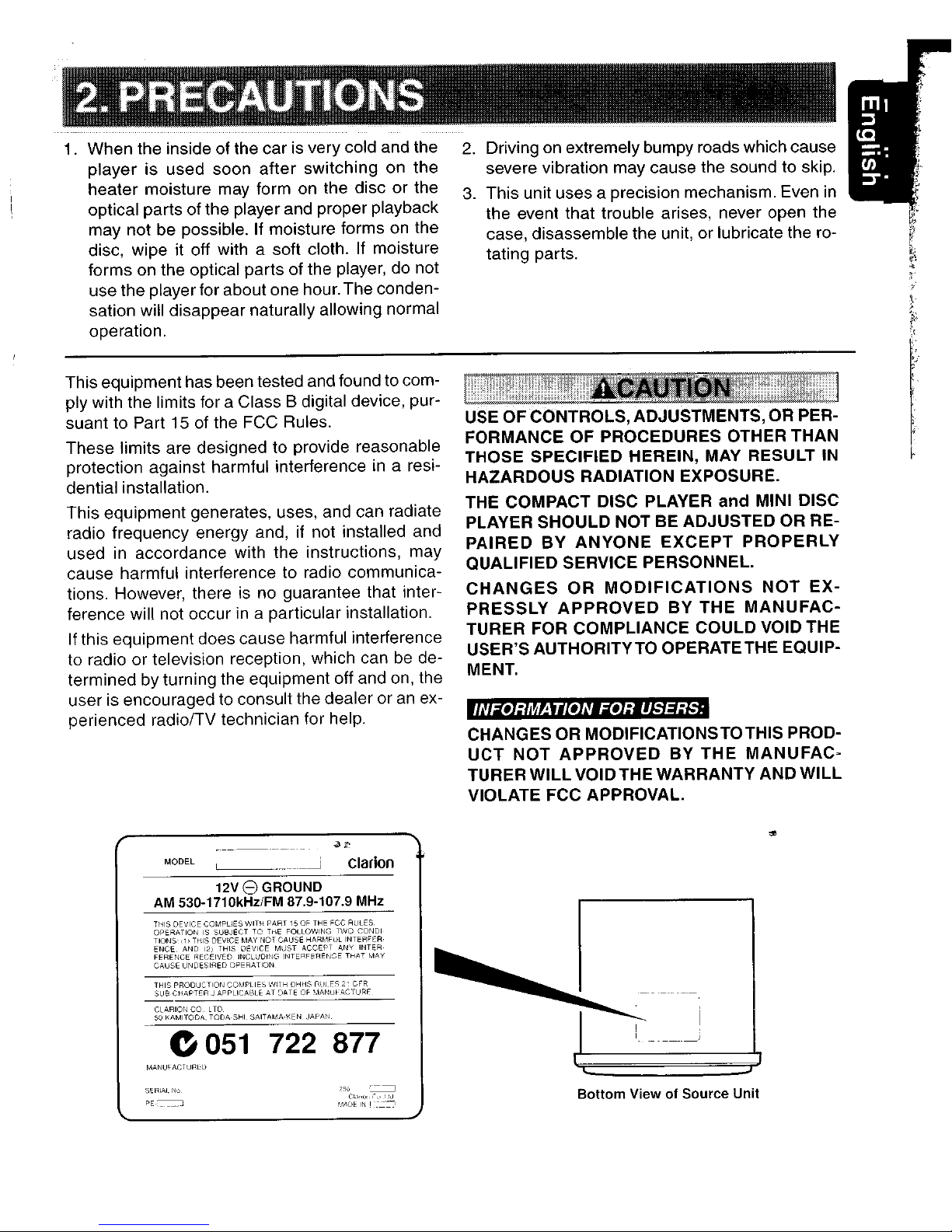
This equipment has been tested and found to comply with the limits for a Class B digital device, pursuant to Part 15 of the FCC Rules.
These limits are designed to provide reasonable
protection against harmful interference
in
a resi-
dential installation.
This equipment generates, uses, and can radiate
radio frequency energy and, if not installed and
used in accordance with the instructions, may
cause harmful interference to radio communica-
tions. However, there is no guarantee that inter-
ference will not occur
in
a particular installation.
If
this equipment does cause harmful interference
to radio or television reception, which can be de-
termined
by
turning the equipment off and on, the
user is encouraged to consult the dealer or
an
ex-
perienced radio/TV technician for help.
2.
Driving on extremely bumpy roads which cause I
severe vibration may cause the sound to skip.
3.
This unit uses a precision mechanism. Even
in
the event that trouble arises, never open the
case, disassemble the unit, or lubricate the ro-
tating parts.
USE OF CONTROLS,ADJUSTMENTS,OR PERFORMANCE
OF
PROCEDURES OTHER THAN
THOSE SPECIFIED HEREIN, MAY RESULT
IN
HAZARDOUS RADIATION EXPOSURE.
THE COMPACT DISC PLAYER
and
MINI DISC
PLAYER SHOULD NOT BE ADJUSTED OR REPAIRED
BY
ANYONE
EXCEPT
PROPERLY
QUALIFIED SERVICE PERSONNEL.
CHANGES
OR
MODIFICATIONS
NOT
EX-
PRESSLY
APPROVED
BY
THE
MANUFACTURER FOR COMPLIANCE COULD VOID THE
USER'S AUTHORITYTO OPERATETHE EQUIPMENT.
CHANGES OR MODIFICATIONSTOTHIS PROD-
UCT
NOT
APPROVED
BY
THE
MANUFAC·
TURER
WILL
VOIDTHE WARRANTY AND
WILL
VIOLATE FCC APPROVAL.
MODEL
Clarion
e
051
722 877
MANU~ACTURl:Ll
SERIAL
~Io
PE·, J
Bottom
ViewofSource Unit
Page 4
Motorized Face
This unit uses motorized face to make largescreen displays possible.
When you use the motorized face, be sure to
close it.
BE CAREFUL NOTTO GETYOUR FINGERS
CAUGHTWHEN OPENING AND CLOSING
THE MOTORIZED FACE.
1.
For safety's sake, always close the MOTORIZED FACE before leaving this unit unused
for a prolonged period or switching OFF the
ignition
key.
If you switch OFFthe ignition key with the
MOTORIZED FACE tilted, the MOTORIZED
FACE does not close.
Handling Compact Discs
Use only compact discs bearing the
ffi]o~©
or
• mark. DIGITAL AUDID
Do not play heart-shaped, octagonal, or other
specially shaped compact discs.
Some CDs recordedinCD-R/CD-RW mode may
not be usable.
Handling
• Comparedtoordinary music
CDs,
CD-R and CD-
RW
discs are both easily affectedbyhigh temperature and humidity and some of CD-R and
CD-RW discs may notbeplayed. Therefore, do
not leave them for a long timeinthe
car.
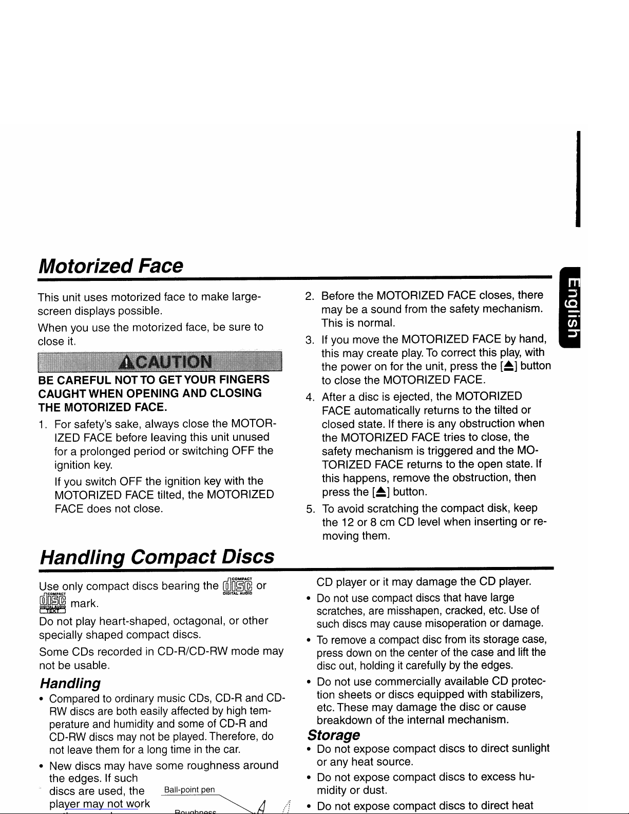
• New discs may have some roughness around
the edges. If such
discs are used, the Ball-point pen
player may not work
2.
Before the MOTORIZED FACE closes, there
may be a sound from the safety mechanism.
This is normal.
3.Ifyou move the MOTORIZED FACE by hand,
this may create play.Tocorrect this
play,
with
the power on for the unit, press the
[~]
button
to close the MOTORIZED FACE.
4.
After a disc is ejected, the MOTORIZED
FACE automatically returns to the tilted or
closed state. If there is any obstruction when
the MOTORIZED FACE tries to close, the
safety mechanism is triggered and the MOTORIZED FACE returns to the open state. If
this happens, remove the obstruction, then
press the
[~]
button.
5.
To
avoid scratching the compact disk, keep
the 12 or 8 cm CD level when insertingorremoving them.
CD player or it may damage the
CD
player.
•
Do
not use compact discs that have large
scratches, are misshapen, cracked, etc. Use
of
such discs may cause misoperation or damage.
•
To
remove a compact disc from its storage
case,
press downonthe center of the case and lift the
disc out, holdingitcarefully by the edges.
• Do not use commercially available CD protection sheets or discs equipped with stabilizers,
etc. These may damage the disc or cause
breakdown of the internal mechanism.
Storage
• Do not expose compact discs to direct sunlight
or any heat source.
• Do not expose compact discs to excess humidity or dust.
• Do not expose compact discs to direct heat
Page 5

Page 6
I
Note:
• Be sure to read this chapter referring to the front diagramsofchapter
"3.
CONTROLS"on page 5 (unfold).
Names
of
the Buttons
and
their Functions
[OPEN] button
• Deeply push
in
[OPEN] button to unlock the
flip down panel.
[ROTARY] knob
• Adjust the volume by turning the knob clockwise or counterclockwise.
• Use the knob to perform various settings.
[FUNC] button
• Press the button to turn on the power.
Press and hold the button for 1second or
longer to turn off the power.
• Switches the operation mode among the radio mode, etc.
[DIRECT] button
• Stores a station into memory or recall it directly while
in
the radio mode.
[ROM] button
• Performs random play whileinthe CD mode.
[RPT] button
• Repeat play whileinthe CD mode.
[BAND] button
• Switches the band, or seek tuning or manual
tuning while
in
the radio mode.
• Plays a first track while
in
the CD mode.
[ISR] button
• Recalls ISR radio stationinmemory.
• Press and hold for 2 seconds or longer:
Stores current station into ISR memory (radio
mode only).
[Z-E] button
• Use the button to select one of the three
types of sound characteristics already stored
in
memory.
[DISP] button
• Switches the display indication(Main
display,clock display).
[SCN] button
• Performs preset scan whileinthe radio mode.
When the button is pressed and held, auto
store
is
performed.
• Performs scan play for 10 seconds for each
track while
in
the CD mode.
[A-M] button
• Press and hold the button for 1 second or
longer to make the System Adjustments.
• Use the button to switch to the audio mode
(bass/treble, balance/fader Z-Enhancer Plus,
loudness adjustment)
[<"'],
[~>]
button
• Selects a station whileinthe radio mode or
selects a track when listening to a
CD.
These
buttons are used to make various settings.
• Press and hold the button for 1 second or
longerto switches the fast-forward/fast-backward.
[~/II]
button
• Plays or pauses a CD whileinthe CD mode.
[~]
button
• Ejects a CD when it is loaded into the unit.
[CD SLOT]
• CD insertion slot.
Page 7
Major button operations when external equipment is
connected to this unit
I
.When
the CD/MD/DVD changer
is connected
'-'
For details, see the section
"CD/MD
changer operations". For the DVD
changer, refer to the Owner's Manual provided with the DVD changer.
[DIRECT] button
o Designates the disc to
be
played.
[RDM] button
o Performs random
play.
Also performs disc ran-
dom play when the button is pressed and held
[RPT] button
o Performs repeat
play.
When
this button
is
pressed
and
held, disc repeat playisperformed.
[BAND] button
o Moves the next disc
in
increasing order.
[SCN] button
o Performs scan play for 10 seconds for each
track. Disc scan play is performed when the
button is pressed and held.
[<<Ill],
[~>]
button
o Selects a track when listening to a disc.
o Press and hold the button for 1 second or
longer to switches the fast-forward/fast-backward.
[~/II]
button
o Plays or pauses a
CD,
MD or
DVD.
• When the Sirius Satellite
Radio is connected
.',For details, refer to the Owner's Manual
provided with the Sirius Satellite Radio.
[FUNC] button
o Press the button to switch the operation mode
among the SIRIUS mode, etc.
[SCN] button
o Performs category scan while
in
the SIRIUS
mode. When the button is pressed and held,
preset scan is performed.
[DIRECT] button
o Stores a station into memory or recall
it
di-
rectly while
in
the SIRIUS mode.
[<<Ill],
[~>]
button
o Press the button
to
selects a station.
~~
WhatisSirius
Satellite
Radio?
~~~!~d~
Sirius is radio the way it was meant to be: Up to
100 new channels of digital quality programming
delivered to listeners coast to coast via satellite.
That means 50 channels of completely commercial-free music. Plus up to 50 more channels of
news, sports, and entertainment from names
like CNBC, Discovery, SCI-FI Channel, A&E,
House of Blues,
E!,
NPR, Speedvision and
ESPN.
Sirius is live, dynamic entertainment, completely
focused on listeners. Every minute of every day
of every week will be different. All 50 commercial-free music channels are created in-house
and hosted by DJs who know and love the music. Do you like Reggae? How about Classic
Roek or New Rock? Sirius has an array of
choices spanning a vast range of musical tastes
including the hits of the 50's, 60's, 70's, & 80's
as well as Jazz, Country, Blues,
Pop,
Rap, R&B,
Bluegrass, Alternative, Classical, Heavy Metal,
Dance and many others
...
From its state-of-the-art, digital broadcasting facility
in
Rockefeller Center, New
York
City, Sirius
will deliver the broadest, deepest mix of radio
entertainment from coast to coast.
Sirius will bring you music and entertainment
programming that is simply not available
on
tra-
ditional radio
in
any market across the country.
It's radio like you've never heard before.
So
Get Sirius and Listen Up! For more inforn'fa-
- tion, visit siriusradio.com.
Page 8
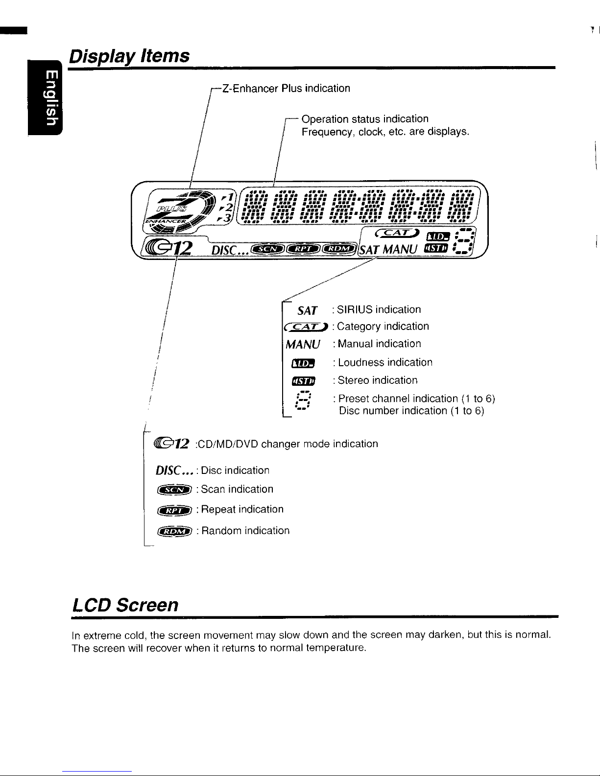
Z-Enhancer Plus indication
Operation status indication
Frequency, clock, etc. are displays.
SAT
:SIRIUS indication
(
CA
T ) : Category indication
MANU
:Manual indication
: Loudness indication
:Stereo indication
: Preset channel indication
(1to6)
Disc number indication(1to
6)
....
....
.....
........
•••••
••
ad
•••••••••••••••
•...•...... ....•...... .
:.:.:.:.: :.:.:.:.:
:
..........
:
:.:.:.:.:
: :
•.........•....•••.........
•••••
•••••
Pa"
••••••••••
....
.....
.....
.....
..
...
.--.
;--;
"_.'
I
,I
IDisplayItems
@12
:CD/MD/DVD changer mode indication
DlSC.••:Disc indication
1~§J
:Scan indication
@'L@I : Repeat indication
@iM! :Random indication
LCD Screen
In
extreme cold, the screen movement may slow down and the screen may darken, but this is normal.
The screen will recover when it returns to normal temperature.
Page 9
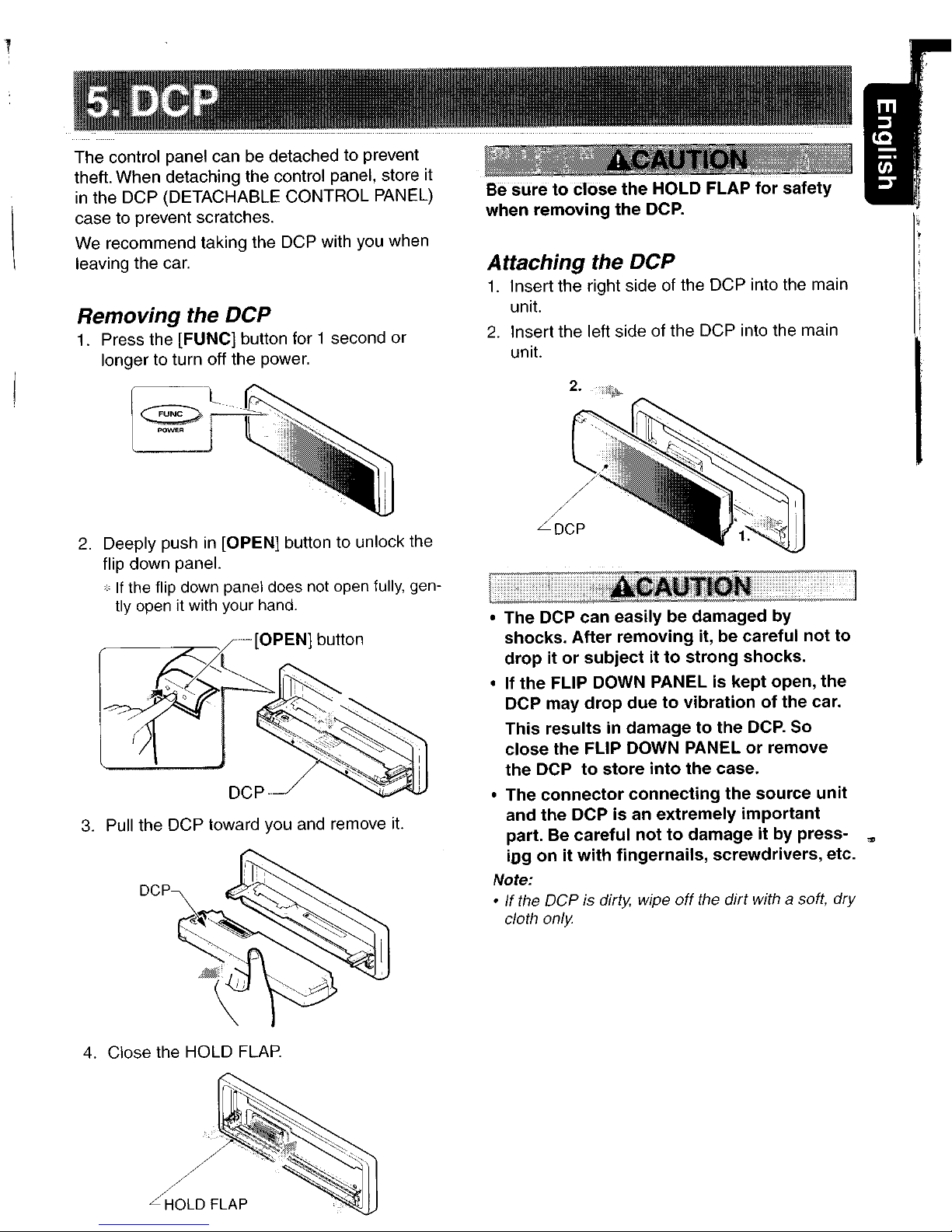
The control panel can be detached to prevent
theft. When detaching the control panel, store it
in
the DCP (DETACHABLE CONTROL PANEL)
case to prevent scratches.
We recommend taking the DCP with you when
leaving the
car.
Removing the DCP
1. Press the [FUNC] button for 1 second or
longer to turn off the power.
Be
suretoc:lose
the
HOLD FLAP
for
safety
when
removing
the
DCP.
Attaching
the DCP
1.
Insert the right side of the DCP into the main
unit.
2.
Insert the left side of the DCP into the main
unit.
I
2.
Deeply pushin[OPEN] button to unlock the
flip down panel.
*
If
the
flip
down
panel does
not
open
fully,
gen-
tly
openitwith
your
hand.
~.
[OPEN] bolloo
DCp·
3.
Pull the DCP toward you and remove
it.
4.
Close the HOLD
FLAP.
~LDFLAP
2.
• The DCP
can
easilybedamaged
by
shocks.
After
removing
it, be careful
not
to
dropitor
subjectitto
strong
shocks.
• If
the
FLIP DOWN PANELiskept
open,
the
DCP may
drop
duetovibrationofthe
car.
This
resultsindamagetothe
DCP.
So
close
the
FLIP DOWN PANELorremove
the
DCP
to
store
into
the
case.
• The
connector
connecting
the
source
unit
and
the
DCPisan
extremely
important
part. Be
careful
nottodamageitby
press-
'"
iD9
onitwith
fingernails,
screwdrivers,
etc.
Note:
•Ifthe DCP is dirty. wipe
off
the dirt with a soft, dry
cloth only
Page 10

r;;;~~;;;;;;;;;;;;;;;;;;;;;;;;;;;;;;;;;;;;;;;;;;;;;;;;;;;;;;;;;;;;;;;;;;;;;;;~~~~T-
Receiver for remote control unit
Operating range:
30'
in
all directions
--
Signal transmitter
Remote control unit
,..--,-++--[~/II]
~~;-i--[
<<II
],[~>
]
-+--:--[BAND]
H-'i---
[DISP]
II
SGN
RPT
ROM
II
[SeN]
-7--
1
+-'1
~
r
~H-I
;-'--[RDM]
[RPT]
l~ooJ
Inserting the Batteries
Rear
cover
I
<?~
1.
Turn the remote control unit over, then slide the
rear cover
in
the direction of the arrow.
2.
Insert the AA (SUM-3, IECR-6/1.5V) batteries
that came with the remote control unit facing
in
the directions showninthe figure, then close the
rear cover.
Notes:
Using batteries improperly can cause them to
explode. Take note
of
the following points:
• When replacing batteries, replace both batteries
with new ones.
• Do not short-circuit, disassemble
or
heatbatteries.
• Do
not
disposeofbatteries into fireorflames.
• Dispose
of
spent batteries properly.
~
AA
(SUM-3. IECR-6/1.5V)
Batteries
@
@rolg;J
\_-
o~i~
~.~
Rear side \""0/
Page 11

.~~
CD~MQc~a"g~r
g",~.",u
"'-
[FUNC]
Switches among radio, SIRIUS tuner,
CD,
CD/MD changer,
DVD
changer and AUX.
[BAND]
Switches reception band. Plays the first track.
Moves the next disc
in
Top
play.
increasing order.
[A],[T]
Increases and decreases volume
(in
all modes).
[<
..
],[~>]
Moves preset
Moves tracks up and down.
channels up and
When pressed and held for 1 second:
down.
Fast-
fo
rward/fast-backward.
[~~II]
No function.
Switches between playback and pause.
[MUTE]
Turns mute on and off.
[ISR]
Recalls ISR radio stationinmemory.
Press and hold for 2 seconds or longer: Stores current station into ISR
memory (radio mode only).
[DISP]
Switches among main display, clock display.
[SeN]
Preset scan.
Scan
play.
Scan play.
When pressed and held for 2
When pressed and held for 1
seconds: Auto store. second: Disc scan play.
[RPT]
No functuon
Repeat
play.
Repeat play.
When pressed and held for 1
second: Disc repeat play.
,
w
[ROM]
No functuon
Random play.
Random play.
When pressed and held for 1
second: Disc random play.
FunctionsofRemote
Control
Unit
Buttons
",
Some of the corresponding buttons on the main unit and remote control unit have different functions.
I
Page 12

,
.....
,
'''')
i·C·
.:;~
Clock display
(
-CUSTOM
-Z+
OFF
• EXCITE
Setting
the Z-Enhancer
Plus
This unit are provided with 3 types of sound tone ef-
fects
storedinmemory. Select the one
you
prefer.
The factory default settingis"Z+
OFF".
Each time you press the
[ZoE]
button, the tone
effect changes
in
the following order:
"Z+
OFF"~"B
BOOST"~"IMPACT"~"EX-
CITE"~"CUSTOM"~"Z+
OFF"
...
• B BOOST bass emphasized
- IMPACT bass and treble emphasized
bass and treble empha-
sized mid de-emphasized
user custom
no sound effect
",
Main display
Once selected, the preferred display becomes
the display default. When afunction adjust-
ment such
as
volumeismade,
the
screen
will
momentarily switch to that function's display,
then revert back to the preferred display sev-
eral
seconds after
the
adjustment.
Switching
the
display
Press the [DISPj button to select the desired display.
Each time you press the [DISP] button, the display switches
in
the following order:
Main display
(
Adjusting
the volume
Turning the [ROTARY] knob clockwise increases
the volume; turning it counterclockwise decreases the volume.
'"
The volume
levelisfrom
0 (minimum)to33
(maximum).
Selecting a
mode
1. Press the [FUNC] button to change the op-
eration mode.
2.
Each
time
you
press the [FUNC] button, the
op-
eration mode changesinthe
following order:
Radio mode
~
SIRIUS mode~CD mode
~
CD changer mode~MD changer mode
~
DVD changer mode~AUX mode~Radio
mode
...
'"
External equipment not connected
with
CeNETisnot
displayed.
Note:Besure to
read
this
chapter
referring to the front diagrams
of
chapter
"3.
CONTROLS" on
page
5 (unfold).
Turning
on/off
the
power
Note:
•Becarefulabout using this unit for a long time without running the engine.
Ifyou drain the car's battery
too
far,
you may not be abletostart the engine and
thIs can reduce
the
service lifeofthe battery
1. Press the [FUNC] button.
2. The illumination and display on the unit light
up.
The unit automatically remembers its last
operation mode and will automatically switch
to display that mode.
3. Press and hold the [FUNCj button for 1 sec-
ond
or
longer to turn off the power for the
unit.
Note:
• System check
The first time this unit
is turned on
after
the wire
connections are completed, it
must
check what
equipment
is connected. When the
power
is
turned
on, "SYSTEM"
and
"PUSH
PWR"
appear
in the display alternately, so
press
the
[FUNCj
button. The system check starts within the unit.
When the system check is complete, the
power
is
turned off, so press the
[FUNCj
button again.
Be
suretolower
the
volume
before
switch-
ing
off
the
unit
powerorthe
ignition
key. The
unit
remembers
its
last
volume
setting. If
you
switch
the
power
off
with
the
volume
up,
when
you
switch
the
power
back on,
the
sud-
den
loud
volume
may
hurt
your
hearing and
damage
the
unit.
Page 13

Basic
Operations
Adjusting
the
tone
Press the [A-M] button and select
the
item
to
adjust. Each time you press the [A-M] button,
the item
changes
in the following order:
•
When
"B
BOOST"isset
"B
BOOST"~"BAL
0"
~
"FAD
0"
~
"LOUD
OFF"~Last
function
mode.
•
When
"IMPACT"isset
"IMPACT"~"BAL
0"
~
"FAD
0"
~
"LOUD
OFF"~Last
function
mode.
.When
"EXCITE"isset
"EXCITE"~"BAL
0"
~
"FAD
0"
~
"LOUD
OFF"~Last
function
mode.
•
When
"CUSTOM"isset
"BASS"~"TREB"~"BAL
0"
~
"FAD
0"
~
"LOUD
OFF"~Last
function
mode.
.When
"Z+
OFF"isset
"BAL
0"
~
"FAD
0"
~
"LOUD
OFF"~Last
function
mode.
Adjusting
the
bass
(Gain,
Frequency, Q-curve)
This adjustment can be performed when the Z-
Enhancer Plus is setto"CUSTOM".
1.
Press the [A-M] button and select "BASS".
2. Turning the [ROTARY] knob clockwise emphasizes the bass; turning it counterclockwise attenuates the bass.
;.
The factory default setting is "B<G 0>". (Adjustment range:
-6
to +6)
3.
Press the
[~>]
or
[<
....
] button to select
"B<F
60>".
Turninng the [ROTARY] knob clockwise or
counterclockwise to select the frequency.
.;
The factory default settingis"B<F 60>".(Adjustment 60/100/200 Hz)
4.
Press
the
[~>]
or
[<
....
]button
to
select "B<O 1>".
Turninng the [ROTARY] knob clockwise or
counterclockwise to select the Q-curve.
".
The factory default setting is "B<O 1>".(Ad-
justment 1/1.25/1.5/2)
5.
When the adjustment is complete, press the
[A-M] button several times until the function
mode is reached.
Adjusting
the treble (Gain,
Frequency)
This adjustment can be performed
when
the Z-
Enhancer Plus is set to "CUSTOM".
1. Press the [A-M] button and select "TREB".
2. Turning the [ROTARY] knob clockwise emphasizes the treble; turning it counterclockwise attenuates the treble .
.;
The factory default settingis"T<G0>". (Ad-
justment range:
-6
to +6)
3. Press the
[~>]
or
[<
....
] button to select "T<F
10>".
Turninng the [ROTARY] knob clockwise or
counterclockwise to select the frequency.
.;.
The factory default setting is ''T<F 10>".(Adjustment
10
kHz/15 kHz)
4. When the adjustment is complete, press the
[A-M] button several times until the function
mode is reached.
Adjusting
the balance
1.
Press the [A-M] button and select "BAL".
2. Turning the [ROTARY] knob clockwise emphasizes the sound from the right speaker;
turning it counterclockwise emphasizes the
sound from the left speaker.
The factory default setting is "BAL
0".
(Adjust-
ment range:
L
13
to R13)
3.
When the adjustment is complete, press the
[A-M] button several times until the function
mode is reached.
Adjusting
tile
fader
1. Press the [A-M] button and select "FAD".
2.
Turning the [ROTARY] knob clockwise emphasizes the sound from the front speakers;
turning it counterclockwise emphasizes the
sound from the rear speakers.
The factory default setting
is
"FAD
0".
(Adjust-
ment range:
F12toR12)
3.
When the adjustment is complete, press the
[A-M] button several times until the function
mode is reached.
I
Page 14

I
Basic Operations
Adjusting
the Z-Enhancer Plus
1.
Press the
[ZoE]
button and select the Z-En-
hancer Plus mode to adjust.
2.
Press the [A-M] button and turning the [RO-
TARY] knob clockwise adjusts in the
+ direc-
tion; tuning it counterclockwise adjusts
in
the
- direction.
.When
"B
BST
0" selected, you can adjust
the bass
in
the range of -3 to
3.
.When
"IMPACT 0" selected, you can adjust
the bass and treble
in
the range of -3 to
3.
• When "EXCITE 0" selected, you can adjust
the bass and treble
in
the range of -3 to
3.
:.
When Z-Enhancer Plusisselected, press
and
hold
the
[ZoE]
button for 2 seconds or longer
to change the "CUSTOM"
mode.
Bass/treble charasteristics become flat
and
the indication "--FLAT--"isshowninthe display.
Press the
[ZoE]
button againtochange
the
"Z+
OFF"
mode.
Turning
on/off
the loudness
The loudness effect emphasizes the bass to
create a natural sound tone. When you are listening to music at a low volume, it is recom-
mended to use the loudness effect.
1.
Press the [A-M] button to select "LOUD
OFF".
2.
Turning the [ROTARY] knob clockwise
or
counterclockwise to select "LOUD ON"(on)
or
"LOUD OFF"(off).
When loudness effect is turned on, "LD"lights
on the display.
The factory default setting
is
"LOUD
OFF".
Radio Operations
FM reception
For
enhanced
FM
performance
the
mRIiI:rUNECJ"'
tuner includes signal actuated stereo control,
Enhanced Multi AGe, Impulse noise reduction
curcuits and Multipath noise reduction circuits.
Changing the reception area
This unitisinitially set to USA frequency intervals
of
10kHz for
AM
and 200kHz for
FM.
When using
it
outside the USA, the frequency reception range
canbeswitched to the intervals below.
•
Setting
the
reception
area
1.
Press the [BAND] button and select the desired radio band (FM
or
AM).
2.
While pressing the [DISP] button, each time
you press and hold the number "6" of the [DIRECT] buttons for 2 seconds
or
longer, the
reception area switches from inside the USA
to outside the USA or from outside the USA
to inside the USA.
:.
Any
station preset memories
are
lost
when
the
reception area
is
changed.
Listening
to the radio
1.
Press the [FUNC] button and select the radio
mode. The frequency appears
in
the display.
2.
Press the [BAND] button and select the radio
band. Each time the button
is
pressed, the ra-
dio reception band changes
in
the following
order:
FM1~FM2~FM3~AM~FM1
...
3.
Press the
[<
....
] or
[~>]
button to tuneinthe
desired station.
Tuning
There are 3 types of tuning mode available, seek
tuning, manual tuning and preset tuning.
Page 15

Seek
tuning
1.
Press the [BAND] button and select the desired band (FM or AM).
."If"MANU"islitinthe
display,
press
and
hold
the [BAND] button for 1 second or longer.
"MANU"
in
the display goes off
and
seek tun-
ingisnow available.
2.
Press the
[<
...] or
[~>]
button to automatically
seek a station.
When the
[~>]
buttonispressed, the station
is
soughtinthe direction of higher frequencies;
if
the
[<
...] button
is
pressed, the stationissought
in
the directionoflower frequencies.
Manual
tuning
There are 2 ways available: Quick tuning and
step tuning.
When you are
in
the step tuning mode, the fre-
quency changes one step at a time.
In
the quick
tuning mode, you can quickly tune the desired
frequency.
1.
Press the [BAND] button and select the desired band (FM
or
AM).
If
"MANU"isnot litinthe
display,
press
and
hold
the [BAND] button for 1 secondorlonger.
"MANU"
is
litinthe
display
and
manual tuning
is
now
available.
2.
Tune into a station.
.Quick
tuning:
Press and hold the
[<
...]
or
[~>]
button for 1
second or longer to tune
in
a station.
.Step
tuning:
Press the [<
...
]or
[~>]
button to manually
tune
in
a station.
"r
Recalling a
preset
station
A total of24preset positions (6-FM1, 6-FM2,
6-
FM3, 6-AM) exists to store individual radio sta-
tions
in
memory. Pressing the corresponding
[DIRECT] button recalls the stored radio fre-
quency automatically.
1.
Press the [BAND] button and select the desired band (FM or AM).
2.
Press the corresponding [DIRECT] button to
recall the stored station.
Press
and
hold
oneofthe
[DIRECT] buttons
for 2 seconds
or
longer to store that station
into preset memory.
Radio Operations I
Manual
memory
1.
Select the desired station with seek tuning,
manual tuning
or
preset tuning.
2.
Press and hold one of the [DIRECT] buttons
for 2 seconds
or
longer to store the current
station into preset memory.
Auto
store
Auto store is a function for storing up to 6 stations that are automatically tuned
in
sequentially.
If 6 receivable stations cannot be received, a
previously stored station remains unoverwritten
at the memory position.
1.
Press the [BAND] button and select the de-
sired band (FM or AM).
2.
Press and hold the [SCN] button for 2 seconds
or longer. The stations with good reception are
stored automatically to the preset channels.
.,.
If auto storeisperformedinthe
FM
bands,
the
stations are stored
in
FM3
evenifFM1orFM2
was chosen for storing stations.
Preset
scan
Preset scan receives the stations storedinpreset memory
in
order. This function is useful
when searching for a desired station
in
memory.
1.
Press the [SCN] button.
2.
When a desired station is tuned in, press the
[SCN] button again to continue receiving that
station.
Note:
• Be careful not
to
press and hold the [SCN] button
for
2 seconds
or
longer. otherwise the auto store
function
is engaged and the unit starts storing
stations. '"
Instant
station
recall (ISR)
Instant station recall is a special radio preset
that instantly accesses a favorite radio station at
a touch of a button. The ISR function even operates with the unit
in
other modes.
.ISR
memory
1.
Selectthe station that you wish to storeinISR
memory.
2.
Press and hold the [ISR] button for 2 seconds
or longer.
•
Recallingastation
with
ISR
In
any mode, press the [ISR] button to turn
on
the radio function and tune the selected radio
station. "ISR" appears
in
the display. Press the
[ISR] button again to return to the previous
mode.
Page 16

I
CD Operations
Loading
a CD
1.
Press the [OPEN] button to access the CD
SLOT behind the FLIP DOWN PANEL.
2. Insert a CD into the centre of the CD SLOT
with the label side facing up.The CD plays
automatically after loading.
Notes:
• Neverinsert foreign objects into the CD
SLOT.
•
If
the
CD
is not inserted easity, there
may
be an-
other
CD
in the mechanismorthe unit may re-
quire service.
• Discs notbearing the
~"[~~
mark andCD-ROMs
cannot be played
by
this unit.
• Some CDs recorded in CD-R/CD-RWmode may
not be usable.
Loading8cm
compact
discs
"Noadapterisrequiredtoplay
an8cm
CD.
,',
Insert the 8
cm
CD
into the centreofthe insertion
slot.
3.
Close the FLIP DOWN PANEL.
Be
careful
nottocatch
your
handorfingers
while
closing
the
FLIP DOWN PANEL.
Notes:
• If the FLIP DOWN PANEL does not open
fully,
gently open with your hand.
• After loading
a
CD,
always close the FLIP DOWN
PANEL.
Listening
to
a CD already
inserted
Press the [FUNC] button to select the CD mode.
Play starts automatically. If no CD is loaded
in
the unit, "NO DISC" appearsinthe display.
Pausing
play
1.
Press the
[~/II]
button to pause play.
"PAUSE" appears in the display.
2.
To
resume CD
play,
press the
[~/II]
button
again.
Ejecting
a CD
1.
Press the [OPEN] button to open the FLIP
DOWN PANEL.
2.
Press the
[~]
to eject the
CD.
Take it out
from the ejected position.
3.
Close the FLIP DOWN PANEL.
Be
careful
nottocatch
your
handorfingers
while
closing
the
FLIP DOWN PANEL.
Notes:
• If the FLIP DOWN PANEL does not open
fUlly,
gently open with your hand.
• After taking out the
CD,
be sure to close the FLIP
DOWN PANEL.
,',
If
a
CD
(12
cm)isleftinthe ejected position
for
15
seconds, the
CDisautomatically reloaded
(Auto
reload).
,',
8
cm
CDs
are
not auto reloaded.Besuretoremove
it
when
ejected.
Note:
• Ifyou force a CD into before auto reloading, this
can damage the
CD.
Selecting a track
.Track-up
1.
Press the
[~>]
button to move ahead to the
beginning of the next track.
2.
Each time you press the
[~>]
button, the
track advances ahead to the beginning of the
next track.
•
Track-down
1.
Press the
[<<lIlI]
button to move back to the
beginning of the current track.
2. Press the
[<<lIlI]
button twice to move to the
beginning of the previous track.
Fast-forward/fast-backward
•
Fast-forward
Press and hold the
[~>]
button for 1second
or
longer.
•
Fast-backward
Press and hold the
[<<lIlI]
button for 1 second or
longer.
Top
function
The top function resets the CD player to the first
track ofthe disc. Press the [BAND] button to play
the first track (track
No.1)
on the disc.
Page 17

I
CD Operations
Scan
play
The scan play locates and plays the first 10 seconds of each track on a disc automatically. This
function continues on the disc until it is cancelled.
,',
The scan play is useful when
you
want to select a
desired track.
1.
Press
the
[SCN]
buttontostart
scan
play.
"SCN" lights in
the
display.
2.
To
cancel the
scan
play, press the [SCN] but-
ton again.
"SCN"
goes
off from the display
and the
current
track continues to play.
Repeat
play
The
repeat play
continuously
plays
the
current
track.
This
function continues automatically until
it is cancelled.
1.
Press the [RPT] button. "RPT" lights in the dis-
play
and
the
current
track is repeated.
2.
To
cancel the repeat play, press the[RPT] but-
ton again. "RPT"
goes
offfrom the display and
normal play resumes.
Random
play
The random play selectsand plays individual tracks
on a disc in no particular order. This function con-
tinues automatically until it is cancelled.
1. Press the [ROM] button. "ROM" lights in the
display, an
individual
track is selected ran-
domly
and play begins.
2.
To
cancel
the
random play, press the [ROM]
button again. "ROM" goesoff and normal play
resumes.
Operations Common to
Each Mode
Hi/Lo
dimmer
control
You
can adjust the reduced illumination level of
the dimmer.
-"
The factory default setting is "ON".
1.
Press and hold the [A-M] button for 1 second
or longer
to
switch to the adjustment selec-
tion display.
2.
Press the
[<
...]
or
[~>]
button to select "DIM-
MER".
3.
Turn the [ROTARY] knob clockwise to "ON"
or counterclockwise to "OFF".
4. Press the [A-M] button to return to the previous
mode.
AUX
function
This system has an external inputjack so you
can listen
to
sounds and music from external
devices connected
to
this unit.
Selecting AUX IN
sensitivity
Make the following settingstoselect the sensitivity when sounds from external devices connected to this unit are difficult to hear even after
adjusting the volume.
'"
The factory default setting is "MID".
1.
Press and hold the
[A-M]
button for 1 second
or longer
to
switch to the adjustment selec-
tion display.
2.
Press the
[<
...]
or
[~>]
button and select
"AUX SENS".
3.
Jurn
the [ROTARY] knob clockwise or counterclockwise as needed and select from
"HIGH", "MID"
or
"LOW".
4. Press the [A-M] button to return to the previous mode.
Setting the
clock
1.
Press and hold the [A-M] button for 1 second
or longer
to
switch to the adjustment selec-
tion display.
2.
Press the
[<
...] or
[~>]
button to select
"CLOCK
En".
3.
Press the
[~/II]
button.
4. Press the
[<
...]
or
[~]
button to select the
hourorthe minute.
Page 18

I
Operations Common to Each Mode
5.
Turn the [ROTARY] knob clockwise or counterclockwise to set the correct time.
'"
The clockisdisplayedin12-hour format.
6.
Press the
[~/II]
button to store the time into
memory.
7.
Press the [A-M] button to return to the previ-
ous mode.
Note:
•
You
cannot set the clock when it is displayed with
only the ignition
on.Ifyou drainorremove the
car's battery
or
take out this unit, the clock is re-
set. While setting the clock.
if
another button
or
operation is selected, the clock set mode is canceled.
Turning the screen saver function
on
or
oft
This unit is provided with the screen saver function.
You
can turn on and off this function.
If the button operation is performed with the
screen saver function on, the operation display
corresponding to the button operation
is
shown
for about
30
seconds and the display returns to
the screen saver display.
" The factory default setting
is
"ON".
1.
Press and hold the [A-M] button for 1 second
or longer to switch to the adjustment selec-
tion display.
2.
Press the
[<~]or[~>]
button and select
"AUTO 88".
3.
Turn the [ROTARY] knob clockwise or coun-
terclockwise to select"ON" or "OFF".
4.
Press the [A-M] button to return to the previ-
ous mode.
The following illustration presents
oneofthe
patterns which
are
shown
when
the
screen
saver function
is
turnedon.
(
, "
....
,
f"!
J
....._"__
4_/'"
__
;-_..:_:
:_:::_:._~_
•••
_ •••_••_._
•••_••
~
Triggered audio mute for cellular
telepones
This unit requires special wiring to mute the audio signal automatically when a cellular tele-
phone rings
in
the car.
'"
This functionisnot compatible wiht
all
cellular
telepones Contact your
local
authorized Clarion
dealer for information
on
proper installation and
compatibility.
Page 19

Selecting
a track
.Track-up
1.
Press the
[~>]
button to move ahead to the
beginning of the next track .
2.
Each time you press the
[~>
1button, the
track advances ahead to the beginning of the
next track.
.Track-down
1.
Press the
[<
...] button to move back to the
beginning of the current track.
2.
Press the
[<
...] button twice to move to the
beginning of the previous track.
CD-ROM
discs
cannot
be played in
the
CD
changer.
_c_a_VM_D_C_h_a_n...:g~e_r_o_p_e_r._a_ti_o_n_s
1
CD/MD
changer
functions
Selecting
an
MD
When an optional CD/MD changer is connected Each [DIRECT] button corresponds to an MD
through the CeNET cable, this unit controls all loaded into the MD changer. Press the correCD/MD changer functions. This unit can control sponding [DIRECT] button
(1to6)
to select the
a total of 2 changers (MD and/or CD). desired disc.
Press the [FUNC] button and select the CD(MD)
.,.Ifan
MDisnot loadedina slotofMD
changer,
changer mode to start
play.
If 2 CD(MD) chang- pressing the [DIRECT]
button
correspondingtoits
ers are connected, press the [FUNC] button to disc numberisinvalid.
select the CD(MD) changer for
play.
.,.If"NO
MAGA"
appearsinthe
display,
insert
the
magazine
into
the
CD
changer.
"DISC
CHK"
ap-
pearsinthe
display
while
the
player
loads
(checks)
the
magazine.
.,.If
"NO
DISC" appearsinthe
display,
eject the
magazine
and
insert discs into
each
slot. Then,
reinsert the magazine
back
into the
CD
changer.
If
"NO
DISC" appearsinthe
display,
load
MDs
into the
MD
changer.
Pausing
play
1.
Press the
[~/II]
button to pause
play.
"PAUS"
appears
in
the display.
2.
To
resume
play,
press the
[~/II]
button again.
Selecting
a CD
Each [DIRECT] button
corresponMto
a disc_
loaded into the magazine.
•
Selectingadisc
from1to
6
Press the corresponding [DIRECT] button
(1
to
6)
to select the desired disc.
•
Selectingadisc
from7to12(only
when
a
12
disc
CD
changerisused.)
Press and hold the [DIRECT] button
(1to6)
for
1 second or longer to select the desired disc.
IfaCDisnot loadedina slotofmagazine, pressing
the [DIRECT] button correspondingtoits
disc
number
is
invalid.
Fast-forward/fast-backward
•
Fast-forward
Press and hold the
[~>]
button for 1 second or
longer.
• Fast-backward
Press and hold the
[<
...] button for 1 second or
longer.
...
Top
function(CD)
The top function plays from the first track (track
No.1) of the disc.
.When
playingadisc1to
6
Press the [DIRECT] button
(1to6)
with the
same number as the CD playing.
.When
playingadisc7to12(only
when
a
12
disc
CD
changerisused.)
Press and hold for 1 second or longer the [DIRECT] button
(1to6)
with the same number as
the CD playing.
.
,.Ifa
CDisnot loadedina slotofmagazine, press-
ing
the [DIRECT] button correspondingtoits
disc
numberisinvalid.
Page 20

I
CD/MD Changer Operations
Top
function(MD)
The top function plays from thefirst track (track
No.1)
of the disc. Press the [DIRECT] button
(1
to 6) with the same number as the MD playing.
.','Ifan
MDisnot loadedina
slotofMD
changer,
pressing the [DIRECT] button corresponding
to
its
disc numberisinvalid.
Scan play
Scan play locates and plays the first 10 seconds
of each track on a disc automatically. This function continues on the disc until it is cancelled.
;.
The scan playisuseful
when
you
want to select a
desired track.
1.
Press the [SCN] button to start track scanning. "SCN" lights
in
the display.
2.
To
cancel the scan
play,
press the [SCN] but-
ton again. "SCN" goes off from the display
and the current track continues to
play.
Disc scan play
Disc scan play locates and plays the first 10
seconds of the first track
on
each discinthe currently selected CD (MD) changer.This function
continues automatically until it is cancelled.
Disc scan play
is
useful
when
you
wanttoselect a
desired
CD
(MD).
1.
Press and hold the [SCN] button for 1 sec-
ond or longer. "DISC" and "SCN" light in the
display and disc scan play starts.
2.
To
cancel disc scan
play,
press the [SCN]
button again. "DISC" and "SCN" go off from
the display and the current track continues to
play.
Repeat play
Repeat play continuously plays the current track.
This function continues automatically until it is
cancelled.
1.
Press the [RPT] button. "RPT" lightsinthe
display and the current track is repeated.
2.
To
cancel repeat
play,
press the [RPT] button
again, "RPT" goes off from the display and
normal play resumes.
Disc repeat play
After all the tracks on the current disc have been
played, disc repeat play automatically replays
the current disc over from the first track. This
function continues automatically until itis can-
celled.
1.
Press and hold the [RPT] button for 1second
or
longer. "DISC" and "RPT" lightinthe dis-
play and disc repeat play starts.
2.
To
cancel disc repeat play, press and hold
the [RPT] button again. "DISC" and "RPT" go
off from the display and normal play resumes
on the current track.
Random
play
Random play selects and plays individual tracks
on
the discinno particular order. This function
continues automatically until it is cancelled.
1. Press the [ROM] button."ROM" lights
in
the
display and random play begins.
2.
To
cancel random
play,
press the [ROM] but-
ton again. "ROM" goes off from the display
and normal play resumes.
Disc random play
The disc random play selects and plays individual tracks
or
discs automaticallyinno particular order. This function continues automatically until it
is
cancelled.
1.
Press and hold the [ROM] button for 1 second
or
longer. "DISC" and "ROM" lightinthe
display and disc random play starts.
2.
To
cancel disc random
play,
press and hold
the [ROM] button again. "DISC" and "ROM"
go off from the display and normal play resumes from the current track.
Page 21

Problem
Cause
Measure
Power does not turn
Fuse is blown. Replace with a fuse of the same amperage.
If
on.
the fuse blows again, consult your store of
(No sound
is
pro- purchase.
duced.)
Incorrect wiring. Consult your store of purchase.
No sound output
Power antenna lead is shor-
1.
Turn the unit off.
when operating the
ted to ground or excessive
2.
Remove all wires attached to the power
unit with amplifiers or current is required for antenna lead. Check each wire for a possible
power antenna
remote-on the amplifiers or short to ground using
an
ohm meter.
attached.
power antenna.
3.
Turn the unit back on.
4.
Reconnect each amplifier remote wire to the
power antenna lead one by one. If the
~
amplifiers turn off before all wires are
Gl
attached, use an external relay to provide
c
remote-on voltage (excessive current
Gl
0 required).
Nothing happens
The microprocessor has Turn off the power, then
when buttons are
malfunctioned due to noise, press the
[OPEN] button
pressed. etc.
,,'
"m~
Ih'
DCP.
~"'I
b"oo
P""
Ih'''''1
b,'oo
10'
"~
Display is not accu-
,bool2
""0"
with
,
~
rate.
Ihlo
md •
~
~o
DCP or main unit connec-
Wipe the dirt off with a soft cloth moistened with
tors are dirty. cleaning alcohol.
Compact disc cannot Another compact disc is Eject the compact disc before loading the new
be loaded.
already loaded. one.
Sound skips or is noi-
Compact disc is dirty.
Clean the compact disc with a soft cloth.
sy.
Compact disc is heavily Replace with a compact disc with qp scratches.
0
sc~hed
or warped.
u
Sound is bad directly
Water droplets may form
on
Let dry for about 1 hour with the power
on.
after poweristurned
the internal lens when the
on.
car is parked
in
a humid
place.
Page 22

If
an
error
occurs,
one
of the following displays is displayed.
Take
the
measures
described
belowtoeliminate
the
problem.
Error Display
Cause
Measure
ERROR 2
A CDiscaught inside the CD deck and is Thisisa failure of CD deck's mechanism
not ejected. and consult your store of purchase.
e
u
ERROR 3
A CD cannot be played due to scratches, Replace with a non-scratched,
etc.
non-warped-disc.
ERROR 6
A CD is loaded upside-down inside the
Eject the disc then reload it properly.
CD deck and does not play.
ERROR 2
A CD inside the CD changer is not This is a failure of CD changer's
loaded. mechanism and consult your store of
purchase.
t
Cl
c:
ltl
.c:
ERROR 3
A CD inside the CD changer cannot
be
Replace with a non-scratched, non-
l,)
e
played due to scratches, etc. warped disc.
U
ERROR 6
A CD inside the CD changer cannot be Eject the disc then reloaditproperly.
played because it is loaded upside-down.
ERROR H Displayed when the temperature
in
the Lower the surrounding temperature and
MD changer is too high and playback has wait for a while to cool off MD changer.
been stopped automatically.
ERROR 2
An
MD inside the
MD
changerisnot This is a failureofMD
changer's
loaded. mechanism and consult your store of
purchase.
t
Cl
c:
ltl
.c:
l,)
ERROR 3
An
MD inside the MD changer cannot be Replace with a non-scratched. non-
e
I
played due to scratches, etc. warped disc.
2:
ERROR 6
An
MD inside the
MD
changer cannot be
Eject the disc then reload it properly.
played because it is loaded upside-down.
Displayed when a non-recorded
MD
is
Load a pre-recorded MDinthe
MD
loadedinthe MD changer. changer.
If
an error display other than the ones described above appears, press the reset button.Ifthe problem
persists, turn off the
power
and consult your store of purchase.
Page 23

II.
SPEClillCATIONS
I
FMTuner
Frequency Range:
87.9 MHz
to
107.9 MHz
Usable Sensitivity:
9 dBf
50dB Quieting Sensitivity:
15 dBf
Alternate Channel Selectivity:
70 dB
Stereo Separation
(1
kHz):
35dB
Frequency Response (±3 dB):
30 Hz to 15 kHz
AM
Tuner
Frequency Range:
530 kHz to 1710 kHz
Usable Sensitivity:
25IJV
CD Player
System:
Compact disc digital audio system
Usable Discs:
Compact disc
Frequency Response
(±1
dB):
10 Hz to 20 kHz
Signal to Noise Ratio
(1
kHz):
100 dBA
Dynamic Range
(1
kHz):
95 dB
Harmonic Distortion:
0.01%
Channel Separation
(1
kHz):
85 dB
Audio
Maximum Power Output:
200 W (50 W X 4 chi
Continuous Average Power Output:
18 W
X 4, into 4
12,
20 Hz to 20 kHz, 1%THD
Bass Control Action (60 Hzl100 Hzl200 Hz):
±15 dB
Treble Control Action (10 kHzl15 kHz):
±12 dB
Line Output Level (CD 1 kHz):
2V
General
Power Supply Voltage:
14.4V DC (10.8 to 15.6 V allowable), negative
ground
Current Consumption:
Less than 15 A
Speaker Impedance:
412 (4
12
to 812allowable)
Weight / Source unit:
3.30
lb.
(1.5 kg)
Weight / Remote control unit:
1 oz. (30
g)
(including battery)
Dimensions / Source unit:
7"
(Width) X2"(Height) X 6-1/8" (Depth)
[178 (W)
X 50 (H) X 155 (D) mm]
Dimensions / Remote control unit:
1-3/4" (Width)
X 4-5/16" (Height) X 1-1/8"
(Depth)
[44 (W)
X 110 (H) X 27
(D)
mm]
Notes:
• Specifications
and
design are subjecttochange without notice for further improvement.
Page 24

Page 25

in
China / ImprimeenChine / ImpresoenChina 2001/8 (D·C)
284-9445-00
InstallationlWire Connection Guide
GUla de instalaci6n/conexi6n de cables
Car
battery
Batterledevoiture
Baterfa
del autom6vil
1. Esta unidad
ha
sido
disenada
para utilizarse
exclusivamente en autom6viles con fuente
de
alimentaci6n de 12
V,
Ynegativo
amasa.
2. Lea cuidadosamente estas instrucciones.
3.
Antesdecomenzar, cerci6resededesconectar el terminal
"8"
de la baterfa. Estoespara
evitar cortocircuitos durante la instalaci6n.
(Figura 1)
1, est exclusivement destine
{;
etre
les voitures avec une alimentation
12
V arnasse negative,
Ure
ces instructions
attentivement
3 Slassurer de
debrancher
la borne de
la
batterie avant de comrnencer. Cela evitera les
court-circuits
pendant
l'installation, (Figure 1)
set
is exclusively for use in cars with a
negative ground,
12
V
power
supply.
disconnect
the
battery"8"termi-
nal before starting.
This
is to prevent
short
cir-
cuits during installation. (Figure
1)
Figure 1 / Figure 1 / Figura 1
G·;;'i.,.
NI
PRECAUCIONES
PARALAINSTALACION
Prepare all articles necessary for installing
the
source unit before
starting.
If you have to
do
any
work
on the
car
body, suchasdrilling holes,
consult your
car
dealer beforehand.
other
screws can
cause damage. (Figure 3)
Avant de toutes les pieces necessaires
pour
installer
2, Installer
l',...,.~",,,,",,.r>d
rizontal, 2)
3, Sji! est necessaire djeffectuer certains travaux sur la carrasserie
conlrrle des
trous~
consulter d'abord votfe concessionnaire
4,
Utilisef les vis fournies
pour
l'insta!lation, LuWisation d'autres vis
peut
causer
des donlrrlaqes, (Figure 3)
1. Antes
de
comenzar, prepare todos los
elementos
necesarios para
instalar la unidad fuente.
2. Instale la unidad con un cingulo
de
30°
sobre
el plano horizontal.
(Figura 2)
3. Si tiene
que
realizar cualquier trabajo en la carrocerfa,
como
tal-
adrado
de
orificios, etc., consulte al
proveedordesu autom6vil.
4. Utilice los tornillos suministrados para la instalaci6n. La utilizaci6n
de otros tornillos podrfa resultar en danos. (Figura 3)
~
",:,:'
Damage
<,,",..
, Endommage
:
Danado
Chassis
/
Ch~lssis
/
Chasis
Figure 3 / Figure 3 / Figura 3
Max.
5/16"(8mm)
Max,
5/16/1
(8
mnll
Max.
5/16"(8mm)
Chassis /
Chassis!
Chasis
Figure 2 / Figure 2 / Figura 2
G·;;'i.,.
Max. 30°
Max. 30
Max. 30°
INSTALLING
THE
SOURCE
UNIT
fiNS
Universal
Mount
use a screwdriverto bend each
stopperofthe universal mounting
bracket inward, then secure the stopper as shown in Figure 4.
locks.
Take care of the top and bottom of the
outer
escutcheon and
mountitso
that all the hooks are locked. (Figure 5)
Ii
universei
1,
PlacerIesupport
de universe!
dans!etableau de bord
s
utiliser un tournevis
pour
vers
rexterieur
chaque languette
du de universel
1
puis fixer les languettes cornrne
sur la Figure
2. Cabler comrne rnontre
dUllS
18
Section 6,
3,
lnserer l'apparei! dansIesupport
de montage universel
jusqu'a
ce qu'i! bloque,
4,
Reperer
Ie
haUl et
Ie
bas de recusson exterieur
etle
manter
de
111aniere
que tous !es crochets sOlent verrouilles, (Figure
5)
•
Montaje
universal
1.
Coloque el
soportedemontaje universal en el tablerodeinstru-
mentos, utilice un destornillador para doblar
cada
reten del
soportedemontaje universal hacia adentro, y
despues
asegure
el reten
como
se muestra en la Figura 4.
2. Conecte los cables
comoS8muestra en la Secci6n 6.
3.
Inserte la unidad fuente en el
soporte
de montaje universal hasta
que
quede
enganchado.
4. Tenga cuidado con la
partes
superior
e inferiordela pieza orna-
mental exterior, y
m6nteladeforma
que
todos
los
ganchos
que-
den bloqueados. (Figura 5)
Some
car
models require special mounting kits for proper instal-
lation. Consult your Clarion dealerfor details.
coming loose.
1)
fJ70deles de voituro necessitent un kit
de
pour
une insta!!ation correcte, ConsulterIereV'6nlCieLJr
pour
les details,
2)
Serrer
fef
mementla!anguette
avant
pour
eviler
que
rappafeil
pilote ne se c!esserre,
Notas:
1)
Algunos modelos de autom6viles requieren juegos de montaje
especiales para realizar
la
instalaci6n apropiada. Solicite los
detal/es
a su proveedor Clarion.
2) Apriete con seguridad el reten frontal para evitar que se afloje
la
unidad fuente.
t
Bottom
Bas
Parte inferior
Spring
Resson
Resorte
Note:
Before attaching
the
universal
mounting
bracket, slightly
bend
the spring
toward
the inside with
your
fingers
and
attach it to
the
side of car.
Remarque:
Avantdefixer universe!, pliez leolerement
ressort vers et fixez-le
sur
voiture.
Nota:
Antesdefijar el soportedemontaje
universal,
doble
ligeramente
el resorte
hacia
el interior con los
dedos
y ffjelo en
la parte lateral del autom6viL
66
66
e
...
//~
Hexagonal bolt
Ecrou hexagonal
Perno hexagonal
Strap
Armature
Banda
*This part is
not
providedinsome
models,
Cette piece n'existe
pas
sur
taus les modeles.
*Esta
piezanose
suministra
con
algunos
modelos.
Stoppers
Languettes
Retenes
i
,nstrument
panel
Tableau
de
bard
Tab/ero
de
instrumentos
Hole
lrnu
Orificio
Outer
escutcheon
Ecusson ext6rieur
Pieza ornamental exterior
.r-~~~
Stoppers
L.angi,ietlEY>
Retenes
Source Unit
Appareil pilote
Unidad fuente
Screwdriver
.J
Toumevis
Destornillador
Installation direction
¢
Sens
d'installation
Direcci6n
de
instalaci6n
Top
Haut
Parte
superior
Outer
escutcheon
side
view
Vue
lateraledeI'ecusson
exterieur
Page 26

• 1. Antes de hacer las conexiones, asegurese
de
desconectar la alimentaci6n de la unidad.
2.
Sea especial mente cuidadoso al dirigir y fijar los cables.
mantengalos alejados del motor, tubo
de
escape, etc.
EI
calor puede
danar
los cables.
3.
Si el fusible se quema, revise las conexiones.
Si esta quemado, reemplace el fusible
por
otro nuevo con
el
mismo
valordeamperaje
que
el original. (Figura 11)
4.
Conecte el cable prolongador
CeNET
completa y
seguramente hasta que chasquee. Para desconectar el
cable, sujete la
parte
de la tapa deslizable y tire hacia
usted.
'I'
Para prolongar 0 ramificar el cable
prolongador
CeNET, utilice un cable prolongador
CCA-520
(2,5 m)
o CCA-521 (0,6 m),
0
un
adaptador
en Y
CCA-519
(vendidos aparte).
'"
Utilice un cable prolongador
CeNET
fabricado
por
Clarion.
5.
Cuando
el fusible de alimentaci6n principal del autom6vil
sea de 15 A
0 menos, adquiera un cable para autom6vil
que pueda reslstlr 15 A
Yali mente esta unidad
directamente desde la baterfa para cerciorarse de que
pueda funcionar normal mente.
Tenga en cuenta
que
para evitar accidentes, debera
instalar un fusible en al cable
que
va a terminales de la
bateria a una distancianosuperior a30cm.
*The position of the fuse differs from vehicle
to
vehicle.
(Refer to Section
~~lpQSHion
du,.:
velie
seion les vehicules.
~0U
sE~chm
*La posici6n del fusible varia segun el veniculo.
(Consulte ia secci6n 6.)
Figure11/
Figure11/
Figura
11
aval)!
fils.
distance
de
(I"wi,v,l"r!Ol:j
do
lYJettrt~
CAUTION ON WIRING/PRECAUTIONS DE
\"A1DI..I"'UII:;;
PRECAUCIONESALEFECTUAR
LAS
CONEXIONES
Los E)!oigner du rnofeUi (Ii'S '!.lVi''''x !I',',cllappel, :jent
cdc,
I a chaleur risque cfencJOflllllaqfH
13.
•1.Be sure to turn the power off when wiring.
2.
Be particularly careful where you route
the
wires.
Keep
them
well away from the engine, exhaust pipe, etc.
Heat may
damage
the
wires.
3.Ifthe
fuse should blow, check that the wiring is correct.
If it is, replace the fuse with a new one with the same
amperage rating
as
the
original one. (Figure 11)
4.
Connect
the
CeNET
extension cable fully and securely
until it locks.
When
the
CeNET
extension cable is pulled,
hold
the
slide cap part and pull it towards you.
ii,
When
the
CeNET
extension cable is extended
or
branches, use extension cable CCA-520 (2.5m)
or
CCA-521 (0.6m), orY-adapter CCA-519 (eachofthem
is sold separately).
'i, Use the
CeNET
extension cable made by Clarion.
5.
When the main power supply fuse in
the
caris15Aor
less, purchase an automotive cable that can withstand 15
A and supply this unit with power directly from the battery
to ensure that the unit will operate normally.
Note that a fuse must be installed at a distance
no
longer
than 30 cm from the cable battery terminal to prevent
accidents.
-5.
!iiI
Figure9/Figure
9 /
Figura
9
Figure
10/
FIglire
10/
Figura
10
•1.Desmonte el panel de control desmontable (DCP).
+ Para instrucciones sobre c6mo desmontar el DCp,
consulte el manual de instrucciones.
2.
Presione la pieza ornamental exterior hacia afuera y
extraigala. (Figura 9)
3.
Inserte y bloquee las placas de enganche. (Figura 10)
4.
Tire de las placas de enganche para extraer la unidad
principal.
vers
re
haul e!
REMOVAUDEPOSEIREMOCION
2 Presser I'ecusson
(Figure 9)
~
-~~Ok
plate .
.
aQUD
d
'
a
crOU
h
,()!
~
aCa
e ganc 0
3,
lnserer e!
vorroUmf~r
los plaquos()cmchet
{FigIUF:1Ui
4
Tire!
SUJ
les
plaquesc1crochet
POW!etiret !'appareil
•1.Remove the Detachable Control Panel (DCP).
ii, For instructions on removing
the
DCP, refertothe
owner's manual.
2.
Press
the
outer escutcheon upward and remove it.
(Figure 9)
3. Insert and lock the
hook
plates. (Figure 10)
4. Pull
the
hook
platestoremove the main unit.
-4.
Ii
1
Ie
ci,wiet do COlllnH:'l!HJe arHoviblo
~:~
los
!!lstnIc1(ons
sur10retraH
du
corl1rnando anlOvible (DCP}, so
d'emploi
-6.
WIRE CONNECTIONS / CONNECTIQUE / CONEXION DE CABLES
To
Front speakers
c> Vers
10
haut parleurs avant
AI
altavoces delanteros
To
Subwoofers
c:>
VersIesubwGolers
AI
altavoces
de
subgraves
To
Rear speakers
c> Vel's Ie
haut-parfeurs
ardere
AI
altavoces traseros
Amplifier
Ampliflcateuf
Amplificador
Q
!o
Rear
speake~s
v~::r~>
ha.ur
paflelw~
AI
altavoces traseros
Q
To
Front speakers
Vel;:;
l1aut-oar!surs avant
AI
altavoces delanteros
DSP/EQ
c
vanzadO
Amplifier
AmpIJf!cateur
Amplificador
When the source unitisconnectedtothe expanded DSP/EO, a sound
signal
is
not generated from both RCA pin cablesofthe source unit
and
speaker output.
Odand est connecle au module DSP/EO, aucun
senOI
c ,,'cst
\)0'-"''''
d,c;s
dO\j;<
FiCA de rapparell source et de
Cuandolaunidad tuente este conectado a DSP/EO, no habra salida de
serial de sonido a traves
de
los
cables clavijas
RCA
de la unidad fuente
nidela
salidadealtavoces.
CeNET extension cable
C{ll)le (j'(;'xtensl'on
CeNET
Cable prolongador CeNET
Cables
RCA
Gris
Black
NOli
Negro
RCA
cables
•
Be
suretoread
this
when
connecting
using
the
RCA
terminals.
l1Il
Lire
attentivement
celie
section
larsduraccordement
utilisant
les
bornes
RCA_
•
Aseguresedeleer
esta
notaalco
nectar
los
terminales
RCA,
•
When
using
external
amplifier
IIlI
LorsdeI'utilisation
(run
amplilicateur
externe
•
Cuando
utiliceunamplificador
externo
Red
RCA
cables
Cflbh.:.~::;
RG!\
Cables
RCA
x
'----X
Speaker
Sortie
Salidadealtavoces
•
When
using
expanded
DSP/EQ
mo<lule
with
external
amplifier
IIlI
torsdeI'utilisalion
d'un
modUle
DSP/EQ
avecunampillicateur
exteme
•
Cuando
uti/iceunmodulo
DSP/EQ
expandido
conelamplificador
interno
terminal for illumination.
AUX
iNPUT Left
Lf,!"I-llf--:l:
!\lJX
8ClllcllE
Entradaauxi
liar
(AUX
INPUT)
del canal izquierdo
AUX
iNPUT Right
l:::hnHf:
1:',
!\LJ><
droite
Entrada auxiliar
(AUX
INPUT)
del canal derecho
Red/
White/
/ Rojo
Connect it to
the,
","
n,~wP'
Red/
Connecttocellular phone mute lead.
Fjrancrv)1
fi
(ip
,~()
,ejl
di,
le!i:qiholle
1110bdC-
Conecteloalconductor de silenciamiento del telefono modular.
Of"
k\
V(Jltun-,
Conecteloalterminaldealimentacl6n
del
autom6vil para
iluminaci6n.
Conectelo al conductor de conexi6n automatica
de
la
alimentaci6n del amplificador
Connect to remote turn-on lead of amplifier.
iii IniH':olnn,n:";iabie
I'al:lpll!,ciii"'"
Blue/White wire (Amplifier turn-on lead)
Fii
h!(~Uihldnc
(1!i
de
rni:"',(
suu,,;.
I , :!ii'!ai)ln rio l'amoLficatoun
Conductor azu'l/blanco (Conductor conexi6ndela
alimentaci6.n'del
amplificador)
Brown
wire
(Phone
mute
lead)
fi/
marmn
(m
de
sourdine de lele,I/Wllel
Conductor
manon
(Conductordesilenciamientodetelefono)
Orange
wire
(Illumination
lead)
Fii
orange (iii d'seiailaye)
Conductor
anaranjado
(conductordeiluminacion)
,..f~~~
-ISO
Connector Extension Lead
r-) proLJ!lDdlGUl lSO
Cable prolongadordeISO
/ 8 Purpura/negro
/ 8 Blanco/negro
/ 8 Verde/negro
/ 8Gris/negro
/ (ijPurpura
/ (ijBlanco
/ (ijVerde
Rear Right
Arriere
droit
Trasero derecho
Black wire (Ground lead)
rIi1:0:1
di
l
1eliC"
Conductor negro (Conductor de puesta amasa)
,------------------------------------------l
I[
Red/RouUe
/ Rojo Front Right I
1r====::::(mr~(JJJJ]JJ)~~
Avant
droit
I
I
I~==~
Delantero derecho
To
external amplifier I
I
Gray White / Blanc / Blanco Front
Left"
~~u~~~i~~~
~~g:~sShort
circuits,donot
remove
the
caps ot I
I
Gn,
(JJJJ]JJ)
Avant gauche
Gris Delantero izquierdo
I
I
I
Red
/ Houge / Rojo Rear Right
1r====::::tmr~(JJJJ]JJ)~!J
Aerier€!
droit
Aunamplificador
externo I
Trasero
derecho
* Para eliminar los cortocircuitos de audio.
no
quite los cas-
I
Bla,ck
White / Blanc /
B~CO
Rear Left quillos protectoresdelos cables
RCA
no
utllizados. I
N
\IWlW
Arriere
gauche
I
I
N~~ro
Trasero Izquierdo I
L J
Rear Left
Arrlere
gauche
Trasero
izquierdo
Front Right
Avant
droit
Delantero derecho
Front Left
Avant gauche
Delantero izquierdo
I Rear
L~yout
iii
Disposition
an/Em'!
• Disposici6n de la parte posterior
Antenna Rear Viewofthe Source
Unit
Anlenne
Vue
arriere de I'apparell
pilote
Antena Vistaposterior de la unidad fuente
u
I
nD9P-t0
H:
CeNET input
LntiE:c
Cel'Jr,:')
EntradadeCeNET
Connect
to
vehicle chassis ground.
.\
Ia
lerre du
j;i1,;ls~:i{;
du
vew:u!e
Conectelo a una parte metalica del chasis del vehfculo
Yellow
wire (Memory
back-Up
lead)
Fd
!a;n:c i!d
di::'
soulier:
ini:~nU!rc'}
Conductor amarillo (Conductor de protecci6n delamemoria)
Red
wire (Power lead)
Fii
lUU;;~)
if!!
d atinH!'1ati·)!:)
Conductor rojo (Conductordealimentacl6n)
Accessory(ij
12
V
i\(",:e~,s(lilG
i_?
V
Accesorio(ij12V
Connect directly
to
battery.
.-
'-'ciHi
dil
"l~;ei:le
- i,:\ i<1l1ell(
Conectelo directamente a la bateria
Note
When installing
the
Source unit, be suretouse the ISO Connector Extension Lead and connect the
Memory
back-up
lead (Yellow Wire)
With
the Power lead (Red wire) from the car side.
[H'"'' "rIle,,,
cu'"
10,,10U,
ISO et klccordezIefll
de soutien
Nota
Cuando instale la unidad fuente, cerci6rese de utilizar el cable prolongador de ISO y de conectar el conductor
de
protecci6n de la
memoria
(conductor amarillo) al conductor de alimentaci6n (conductor rojo)
dellado
del autom6vil.
Page 27

DE
SYSTEMElEJEMPLO
DESISTEMA
CD
Source unit
®
CeNET extension cable
@
V-adapter
@
6-DISC MD changer
®
6 or 12-DISC CD changer
®
RCA extension cable
0
4-Channel power amplifier
®
Front speakers
®
Rear speakers
@l
Monitor/tuner connection cable
@
Video monitor
@
SIRIUS tuner module
@
Powered sub woofer
@
I
DTS/AC3Decorder
®
DVDAlC
@
DTS/AC3 Commander
@
Center speaker
@
Expanded DSP/EO
@
Expanded SIRIUS TUNER
®
2-Channel power amplifier
@
Optical fiber digital cable
@
External unit
CD
Unidad fuente
®
Cable prolongador CeNET
@
Adaptador en Y
@
Cambiador de 6 minidiscos
®
Cambiador de 6 0 12 discos compactos
®
Cable de extension RCA
0
Amplificador de potencia de 4 canales
®
Altavoces delanteros
®
Altavoces traseros
@l
Cable conector del monitorlsintonizador
@
Monitor de video
@
Modulo sintonizador SIRIUS
@
Altavoz de subgraves con amplificador
@
Decodificador DTSIAC3
®
DVD
A/C
@
Controlador DTSI
AC3
@
Altavoz central
@
DSP/EO mejorados
@
Sintonizador SIRIUS mejorado
®
Amplificador de potenciade2 canales
@
Cable digital de fibra optica
@
Unidad externa
exterieur, (audio-visuel)
55
\ \
\ \
@@
interne. (audio)
interne. (audio)
Note:
Use a CeNET extension cabie that is less than 20 m
in
length. (including the V-adapter CCA-519.)
el
manual de
Nota:
Utilice
un
cable prolongador CeNET de menos de 20 m
de
longilud (incluyendo el adaptadorenY CCA-519).
Page 28

CAUTION / "
....
-r."'",
....
,f"%,1\,/
PRECAUCION
PRECAUTION
Remove the stopper following the procedures below when this source unit is installed
without the universal mounting bracket.
1.
Remove the screw from the source unit (Figure 5).
2. Remove the stopper from the source unit (Figure 6).
3.
Install the remove screw to the source unit (Figure 7).
,j,
Securely attach the screw.
Note:
Store the removed stopperina safe place together with the Instruction Manual.
CD
Stopper/LangueHe!Tap6n
@ Source Unit/Module sourcc/Unidad de
la
fuente
® ScrewdriverrToumevis/Destornillador
@ ScrewlVisrTornilio
PRECAUCION
elWi:,nll
des!',,j"'.
Precaution
Retirer la languetteenprocedant comme suit pour installerIemodule source sans la
patte de montage universel.
1.
Retierlavis du module source (Figure 5).
2. Retirer la languette du module source (Figure 6).
3.
Fixer la vis ainsi retiree surIemodule source (Figure 7).
+ Fixer
la
vis a fond.
Remarque:
Ranger la languette retiree en lieu
sOr
avecIemode d'emploi.
Figure
5 I
Figure
5 I
Figura
5
Figure
6 I
Figure
6 I
Figura
6
Figure
7 I
Figure
7 I
Figura
7
•
Fixed
Mount
(Using
the
bracket
originally
equippedinvehicle)
This unit is designed for fixed installationinthe dashboard.
If the vehicle is equipped with a factory-installed radio, install the source unit with the
parts and screws marked
(*).
(Figure 8)
If the vehicle is not equipped with a factory-installed radio, obtainaninstallation kit to
install the source unit in the following procedure.
1.
Secure the mounting brackets to the chassis as showninFigure 8. When the
source unit is installed without the universal mounting bracket, holes exist;
modification, such as drilling new holes, of the mounting brackets may be required
for other models.
2. Wire as shown
in
Installation (Section 6).
3.
Secure the unitinthe dashboard, and then reassemble the dashboard and the
center panel.
In:',lallallon (Section 5)
j
CHi
II del
10
tableau do
POU]
•
Montura
lija
(Usandoelsoporte
originalmente
equipadoenel
vehlculo)
Esta unidad ha sido disei'iado para la Instalaci6n fija en el tablero de instrumentos.
Si
el vehiculo esta equipado con una radio instalada en labrica, instale la unidad de la
fuente con las piezas los tornillos marcados con
(*).
(Figura 8)
Sielvehiculo no esta equipado con una radio instalada en fabrica, obtenga un juego de
insta/aci6n para Instalar
la
unidad delafuente mediante el procedimiento que se da a
continuaci6n:
1.
Asegure los soportes de montajealchasis como se muestra en la Figura 8.
Cuando la unidad de la fuente esta instalada sinelsoporte de montaje universal,
existendo agujeros, puede requerirse una modificaci6n para otros modelos, tal
como perforaci6n de nuevos agujeros.
2. Realice el cableado tal como se muestra
en
instalaci6n (Secci6n 6).
3.
Asegure la unidadenel tablero de instrumentos, y luego vuelva armar el tablero
de instrumentos y
el
panel central.
Figure
8 I
Figure
8 I
Figura
8
CD
Center Panel (Note 1)
@ Mounting bracket
(1
pair for the left and right sides)
® Source Unit
@Pocket
® Dashboard
® 4-Hexagonal SCREW (M5 X 8)i*. (8 mm Max.)
o Note 2
PannfJd.U
cCllirai
(Remarqu8
1)
de moptage(1paire pour dlaquE) c6t(;
~~aUdlG
ci
c!roi)
tv1(J(
luio source
Podle
Tat.lleau
de
bO!'d
4 ViS (M5 X 8j+. (8 mm)
Re!!131C/ue
CD
Panel central (Nota
1)
@ Soporte de montaje
(1
par para el lado derecho e izquierdo)
® Unidad de
la
fuente
@Solsillo
® Panel de instrumentos
® 4 tornillos hexagonales (M5 X 8),j,.
(8
mm como maximo)
oNota 2
*,
:The parts and SCREW with this mark are used to install radio or included in the
installation kit (Note 3).
*:The screws with this mark are originally attached to the vehicle.
Note
1: In some cases, the center panel
may
require some modification (trimming, filling,
etc.).
Note
2:
If
a hook on the installation bracket interferes with the unit,
bend
and
flatten it
with a nipper
or
a similar tool.
Note
3:
If
reattaching screws which have been detached, remove any fifings from the
screws
and
screw mounting bracket.
l'installation de la radio
Of)
mtirer
fes
dep6ts des vis et
cit;
m : Las piezas y los tornillos con esta marca se utilizan para instalar una radio 0 estan
incluidos en
el
juego de instalaci6n. (Nota
3)
*:Los tornillos con esta marca eslan originalmente sujetos
al
vehiculo.
Nota
1: En algunos casos,
el
panel central puede requerr cierta modificaci6n (Recorte,
relleno, etc.).
Nota2:Si un gancho enetsoporle de instalaci6n interfiere con la unidad, d6belo y
aplastelo con una pinzas
de
corte u otra herramienta especial.
Nota3:Para volver colocar los tomillos retirados, quitelas limaduras de los tomillos y
soporte de montaje del tomillo.
Page 29

ADX
SERIES,
PRO
VIDEO&PRO
AUDIO
WARRANTY
INFORMATION
In
Canada
Clarion
Canada,
Inc.
Warranty
Service
Center
2239
Winston
Park
Drive
Oakville,
Ontario
L6H
5R1
(905)
829-4600
www.clarionmultimedia.com
3.lf
you
purchasedaClarion
ADX
Series,
Pro
VideoorPro
Audio
product,besuretocomplete
the
boxonthe
last
pageofthis
form.
clarion
CAR
AIOID()BEYOND
1.
Detach
this
sectionofthe
card
and
keepitwith
your
records.
2.
Retain
your
sales
receipttovalidate
warranty
service.
IMPORTANT:
In
USA:
Clarion
Sales
Corporation
Warranty
Service
Center
661
West
Redondo
Beach
Blvd.
Gardena,CA90247
(310)
327
-9100
InforTnationonClarion
authorized
Warranty
Centers
maybeobtainedbywriting
Clarion
Corporationatthe
address
below
orbycalling
1-800-GO-CLARION.
Product
Registration
for
USA
and
Canada
only
~
-n
i
55
en
;J2
--;
i
::I:
0
~
m
~
i(i
JJ
en
~
I
m
en
~
f;;
'S::
"
70
Other
8 0
Do
not
have
service/access
3D
Do
Not
Own
40MSN
50
Internet
60
Prodigy
20
MacintoshorClone
1 0
America
Online
20
CompuServe
3D
GEnie
1 0
IBMPCor
Clone
Clarion
offers
two-year
warranty
coverageonADX
Series,
Pro
Video,
and
Pro
Audio
products
(excluding
speakers)
ONLYifthe
productisinstalledatthe
same
location
where
purchased.Ifnot
installedbythe
authorized
dealer.
one-year
warranty
coverageisprovided.
To
obtain
two-year
warranty
coverageonyour
Clarion
ADX
Series,
Pro
Video,orPro
Audio
product,
excluding
speakers,
complete
this
sectioninfull
and
returnitalong
with a
copyofyour
receipt
and
the
attached
product
registration informationinan
envelope
addressed
to:
Clarion
Sales
Corporation
P.O.
Box
863
Brea,CA92822-0863
Own
Intendtobuy
Own
Intendto buy
Home
Desktop
PC
10
90
Satellite
System/Service
170
240
Laptop
Computer
20
100
Cellular
Telephone
180
250
Color
Monitor
3D
110
Pager
190
260
CD-ROM
40
120
Call
Waiting
200
270
Computer
Speakers
50
130
Karaoke
210
280
Color
Printer
60
140
Vehicle
Navigation
System
220
290
Modem
70
150
Vehicle
Security
System
230
300
Large
Screen
lV
(35"
or
larger)
80
160
II
Is
this
your
first
Clarion
purchase?
10 1stpurchase
2 0
2nd
purchase
3 0
3rdormore
II
What
typeofcomputerdoyou
own?
III
Which
on-line service/networkdoyou
subscribe
to?
II
Whichofthe
following products/servicesdoyou
ownorintend
t.o
buy
within
the
next18months?
Page 30

clarion
WAR
RANTYIN
FOR
MAT
ION
D:l!DmPRODUCT
REGISTRATION
CAROl
• What is your
age?
(Optional)
1l::J:]1.._...;;M;,;,;a;,;;ri;,;,;ta;;.I.;.Sta.;;;.;.;tu;.;;,S?,;..
,;,;;(O.:;.'P;,;,;tio;,;,;na~lj~..;;2.:o0.:.;;,;Ma;;.m;,;;·e;.;;,d_..;3.;;0;;.S,;.in..;;g,.;.le
100
New
Age
110Easy
Listening
120Alternative
190
Other
90
Homemaker
100
Student
110
Retired
120
Other
100
$90,000 -
$99,999
11
0 $100,000
and
over
70
VocationlTechnical
School
5017&up
70
$60,000 -
$69,999
80
$70,000 -
$79,999
90
$80,000-$89,999
90
Reggae
170
Appearance/Design
180
EaseofOperation
70
RecommendedbyStore
Salespe~on
8 0
On-line
Information
90
Clarion
Web
Site
10
0
Store
Display
110Special
Promotion
120
Other
50
Clerical/Service
Worker
60
TradesmanlMachine
Operator/Laborer
70
Selt-Employed/Business
Owner
8 0
Food
Service
40
Completed
College
50
Some
Graduate
School
60
Completed
Graduate
School
40
$30,000
- $39,999
50
$40,000 - $49,999
60
$50,000-$59,999
60
Classical
160Features
30
Blues
140
Price
GroupB(Please
check
two)
130
Warranty
150Quality/Reliability
10
Newspaper
Advertisement
20
TV
Comme~cfal
30
Radio
Commercial
40
Magazine
Advertisement
50
RecommendedbyFriend/Family
60
Clarion
Name/Reputation
10
Under
$10,000
20
$10,000-$19,999
30
$20,000-$29,999
10
Some
High
School
2Q
High
School
Graduate
30
Some
College
10
ProfessionallTechnical
20
Upper
Management/Executive
30
Middle
Management
40
Sales/Marketing
III
What type of musicdoyou
listen to most often?
(Please
check
one)
1o
Rock
40POP
70Rap
20
Jazz
5 0
Country
8 0
Rhythm&Blues
..
What is your annual household income?
(Optional)
II
Which factors influenced you the
MOST
in choosing this Clarion Product?
GroupA(Please
check
two)
• Are there any children in your household? 10
Yes
If
yes,
please
specify
age
range:
30
1 -
124013
-16
iiiWhat is the highest level
of
education you have completed?
II
What best describes your primary occupation?
f.',
•
Car
Audio
8 0
AM/FM
Cassette
90
AM/FMCDPlayer
100AM/FM
Cassette/CD
Player
110CD
Changer
120Equalizer/DSP
Processor
Module
130Amplifier
140Speakers
II
What is the name of the store where
you
purchased this product?
Thank
you
for
selectingahigh-quality
product
from
Clarion.Wehope
you
are
completely
satisfied
with
your
purchase.
We'd
liketohelp
serve
you
betterbyfinding
out
more
about
your
reasons
for
choosing
Clarion.
Please
takeafew
momentstofill
out
the
registration
informationonthis
card
and
answerafew
questions
about
yourself
and
your
product.
Then,
return
the
cardtoClarion
within
10
daysofpurchase.
Your
answers
willbekept
strictly
confidential.Weappreciate
your
response!
In
Canada,
place
the
cardinan
envelope
and
mail
to:
Clarion
canada,
Inc.,
Warranty
Service
center,
2239
Winston
Park
Drive,
OakVille,
Ontario
L6H
5Rl.
..
0 Mr. 0 Ms. 0 Mrs. 0 Miss
....
<1l
..
..
.."
C
<1l
C>
~
-
C>
..
..
c
..
_.
C>
C>
:::J
..
..
:::J
e
Q.
...
.."
<1l
C
<1l
..
.."
C
C>
::I'
Ol
<>
II
What Clarion product did
you
purchase?
.,
.."
Ol
..
Multimedia
u::l
Ol
<1l
.c
10
Color
LCD
Display/Control
Unit
:::E
20
Color
LCD
Display
-'
.,
..
::I'
I~
30
Cellular
Telephone
'<
Q.
40
Voice-Activated
Navigation
System
C>
;e
c
C>
50
Video
Cassette
Player
c
60TVTuner
<1l
<>
70
Rear
Vision
Camera
<1l
-'
.."
TEAR
THIS
PAGE
OFF
AND
KEEPITWITH
YOUR
RECEIPT!
This
productiswarranted
against
all
defectsinmaterial
workmanship
foraperiod
of
one
year
from
the
dateoforiginal
purchase.
The
conditionsofthis
warranty
and
the
extentofthe
responsibilityofClarion
Corporation
under
this
warranty
areasfollows:
1.
PROOFOFDATEOFPURCHASE
WILLBEREQUIRED
FOR
WARRANTY
SERVICEOFTHIS
PRODUCT.
INFORMATION
ABOUT
CLARION
AUTHORIZED
WARRANTY
SERVICE
CENTERS
MAY
ALSOBEOBTAINEDBYCONTACTINGORWRITING
CLARION
CORPORATIONATTHE
ADDRESS
LISTEDONTHE
FRONTOFTHIS
CARD.
2.
This
warranty
will
become
voidifservice
performedbyanyone
other
thananapproved
Clarion
Warranty
Service
Center
resultsindamagetoproduct.
3.
This
warranty
does
not
applytoany
product
which
has
been
sUbjecttomisuse,
neglect
or
accident,orwhich
has
had
the
serial
number
altered,
defacedorremoved,orwhich
has
been
connected,
installed,
adjustedorrepaired,
other
thaninaccordance
with
the
instructions
furnishedbyClarion
Corporation.
4.
This
warranty
does
not
cover
car
staticorother
electrical
interferences,
tape
head
cleaning
or
adjustments,orlabor
costs
for
the
removalorreinstallationofthe
unit
for
repair.
5.
The
sole
responsibilityofClarion
Corporation
under
this
Warranty
shallbelimitedtothe
repair
or
replacement
thereof,atthe
sole
discretionofClarion
Corporation.
6.Ifit
becomes
necessarytosend
the
productorany
defective
parttoClarion
Corporationoran
authorized
warranty
service
station,
the
product
mustbeshippedinits
original
carton
or
equivalent
carton,
fully
insured,
with
shipping
charges
prepaid.
Clarion
Corporation
will
not
assume
any
responsibility
for
any
lossordamage
incurredinshipping.
7.
ALL
IMPLIED
WARRANTIES
EXCEPTTOTHE
EXTENT
PROHIBITEDBYAPPLICABLE
LAW
SHALL
HAVENOGREATER
DURATION
THAN
THE
WARRANTY
PERIOD
SET
FORTH
ABOVE.
UNDER
NO
CIRCUMSTANCES
SHALL
CLARION
CORPORATIONBELIABLE
FOR
ANY
LOSSORDAMAGE,
DIRECT
OR
CONSEQUENTIAL,
ARISING
OUTOFTHE
USEORINABILITYTOUSE
THE
PRODUCT.
BECAUSE
SOME
STATESDONOT
ALLOW
LIMITATIONSONHOW
LONGANIMPLIED
WARRANTY
LASTS
OR
EXCLUSIONSORLIMITATIONSOFINCIDENTALORCONSEQUENTIAL
DAMAGES,
THE
ABOVE
LIMITATIONSOREXCLUSIONS
MAY
NOT
APPLYTOYOU.
8.
THIS
WARRANTY
GIVES
YOU
SPECIFIC
LEGAL
RIGHTS,
AND
YOU
MAY
ALSO
HAVE
OTHER
RIGHTS
WHICH
VARY
FROM
STATETOSTATE.
9.
Should
you
have
any
difficulties
with
the
performanceofthis
product
during
warranty,orwith
any
Clarion
authorized
service
centers,
you
may
contact
the
Clarion
National
Service
Managersatthe
address
listedonthe
frontofthis
cardorcall
1-800-GO-CLARION
foralistingofAuthorized
Warranty
Service
Centersinyour
area.
281-0607
-00
 Loading...