

Page 1
XERION 3300
Technical
Systems
Hydraulic System
Page 2

410
Page 3

Content
1 Overall hydraulic system
Overall circuit diagram . . . . . . . . . . . . . . . . . . . . . . . . . . . . . . . . . . . . . . . . . . . . . . . . . . . . . . . . . . . 5
Circuit diagram . . . . . . . . . . . . . . . . . . . . . . . . . . . . . . . . . . . . . . . . . . . . . . . . . . . . . . . . . . . . . 6
Overall circuit diagram . . . . . . . . . . . . . . . . . . . . . . . . . . . . . . . . . . . . . . . . . . . . . . . . . . . . . . . . . . . 7
Key to diagram . . . . . . . . . . . . . . . . . . . . . . . . . . . . . . . . . . . . . . . . . . . . . . . . . . . . . . . . . . . . . 7
PFC pump . . . . . . . . . . . . . . . . . . . . . . . . . . . . . . . . . . . . . . . . . . . . . . . . . . . . . . . . . . . . . . . . . . . . 12
Compensating valve . . . . . . . . . . . . . . . . . . . . . . . . . . . . . . . . . . . . . . . . . . . . . . . . . . . . . . . . 12
Initial position (engine OFF) . . . . . . . . . . . . . . . . . . . . . . . . . . . . . . . . . . . . . . . . . . . . . . . . . . 14
Low-pressure standby . . . . . . . . . . . . . . . . . . . . . . . . . . . . . . . . . . . . . . . . . . . . . . . . . . . . . . 16
Pump starts pumping . . . . . . . . . . . . . . . . . . . . . . . . . . . . . . . . . . . . . . . . . . . . . . . . . . . . . . . 18
Constant volume flow . . . . . . . . . . . . . . . . . . . . . . . . . . . . . . . . . . . . . . . . . . . . . . . . . . . . . . . 20
Downstroking the PFC pump . . . . . . . . . . . . . . . . . . . . . . . . . . . . . . . . . . . . . . . . . . . . . . . . . 22
Maximum pressure limitation (pressure relie f valve function), maximum standby pressure . 24
2 Steering hydraulics
System concept . . . . . . . . . . . . . . . . . . . . . . . . . . . . . . . . . . . . . . . . . . . . . . . . . . . . . . . . . . . . . . . 27
Description . . . . . . . . . . . . . . . . . . . . . . . . . . . . . . . . . . . . . . . . . . . . . . . . . . . . . . . . . . . . . . . 27
Fully hydraulic steering (Emergency steering) . . . . . . . . . . . . . . . . . . . . . . . . . . . . . . . . . . . . . . 31
Circuit diagram . . . . . . . . . . . . . . . . . . . . . . . . . . . . . . . . . . . . . . . . . . . . . . . . . . . . . . . . . . . . 32
Key to diagram . . . . . . . . . . . . . . . . . . . . . . . . . . . . . . . . . . . . . . . . . . . . . . . . . . . . . . . . . . . . 33
Orbitrol axle = Floating axle (1), the rigid axle (2) is tracked by electro-hydraulic means . . . 37
Circuit diagram . . . . . . . . . . . . . . . . . . . . . . . . . . . . . . . . . . . . . . . . . . . . . . . . . . . . . . . . . . . . 38
Key to diagram . . . . . . . . . . . . . . . . . . . . . . . . . . . . . . . . . . . . . . . . . . . . . . . . . . . . . . . . . . . . 39
Orbitrol axle = Rigid axle (2), the floating axle (1) is tracked by electro-hydraulic means . . . 43
Circuit diagram . . . . . . . . . . . . . . . . . . . . . . . . . . . . . . . . . . . . . . . . . . . . . . . . . . . . . . . . . . . . 44
Key to diagram . . . . . . . . . . . . . . . . . . . . . . . . . . . . . . . . . . . . . . . . . . . . . . . . . . . . . . . . . . . . 45
The floating axle (1) and the rigid axle (2) are steered electro-hydraulically – the Orbitrol
steering circuit is closed. . . . . . . . . . . . . . . . . . . . . . . . . . . . . . . . . . . . . . . . . . . . . . . . . . . . . . . . 49
Circuit diagram . . . . . . . . . . . . . . . . . . . . . . . . . . . . . . . . . . . . . . . . . . . . . . . . . . . . . . . . . . . . 50
Key to diagram . . . . . . . . . . . . . . . . . . . . . . . . . . . . . . . . . . . . . . . . . . . . . . . . . . . . . . . . . . . . 51
Steering valve VI . . . . . . . . . . . . . . . . . . . . . . . . . . . . . . . . . . . . . . . . . . . . . . . . . . . . . . . . . . . . . . . 55
Graphics . . . . . . . . . . . . . . . . . . . . . . . . . . . . . . . . . . . . . . . . . . . . . . . . . . . . . . . . . . . . . . . . . 56
Key to diagram . . . . . . . . . . . . . . . . . . . . . . . . . . . . . . . . . . . . . . . . . . . . . . . . . . . . . . . . . . . . 57
Content
410
3 Working hydraulics
Working hydraulics circuit diagram . . . . . . . . . . . . . . . . . . . . . . . . . . . . . . . . . . . . . . . . . . . . . . . 59
Circuit diagram . . . . . . . . . . . . . . . . . . . . . . . . . . . . . . . . . . . . . . . . . . . . . . . . . . . . . . . . . . . . 60
Key to diagram . . . . . . . . . . . . . . . . . . . . . . . . . . . . . . . . . . . . . . . . . . . . . . . . . . . . . . . . . . . . 61
Main valve block . . . . . . . . . . . . . . . . . . . . . . . . . . . . . . . . . . . . . . . . . . . . . . . . . . . . . . . . . . . . . . . 63
Graphics . . . . . . . . . . . . . . . . . . . . . . . . . . . . . . . . . . . . . . . . . . . . . . . . . . . . . . . . . . . . . . . . . 64
Key to diagram . . . . . . . . . . . . . . . . . . . . . . . . . . . . . . . . . . . . . . . . . . . . . . . . . . . . . . . . . . . . 65
000 293 646 0 - SYS-H XERION 3300 - 04/05 3
Page 4

Content
410
4 000 293 646 0 - SYS-H XERION 3300 - 04/05
Page 5

1 Overall hydraulic system
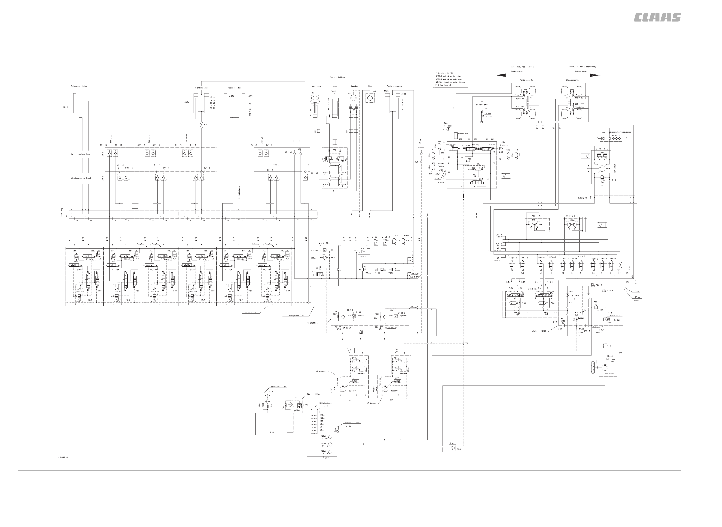
Overall circuit diagram
1 Overall hydraulic system
Overall circuit diagram
387
000 293 646 0 - SYS-H XERION 3300 - 04/05 5
Page 6
1 Overall hydraulic system
Overall circuit diagram
Circuit diagram
387
323-1 323-2
408
400996
6 000 293 646 0 - SYS-H XERION 3300 - 04/05
Page 7
1 Overall hydraulic system
Overall circuit dia gram
Key to diagram
Item Component
I Main valve block
II Cab valve block
III Distributor block
IV Orbitrol steering valve
V Steering sense valve
VI EHL valve block – Electro-hydraulic steering
VII Main brake valve
VIII Working hydraulics variable-displacement pump
IX Steering hydraulics variable-displacement pump
1 Overall hydraulic system
Overall circuit diagram
391
-102-1 Working hydraulics pressure filter
102-2 Steering hydraulics pressure filter
107 Oil drain
109 Hydraulic system oil cooler
110 Oil tank
112 Return filter
113-1 Working hydraulics suction filter
113-2 Steering hydraulics suction filter
113-3 Emergency steering suction filter
116 Resonance tube (Silencer)
117 Fresh air filter element
-205 Working hydraulics pump
214 Hydraulic motor
218 Steering hydraul ics pump
245 Emergency steering pump
-323-1 Floating axle steering hydraulic cylinder
323-2 Rigid axle steering hydraulic cylinder
377 Variable-displacement pump hydraulic cylinder
3007-1a Service brake hydraulic cylinder
3007-1b Service brake hydraulic cylinder
3007-2a Service brake hydraulic cylinder
000 293 646 0 - SYS-H XERION 3300 - 04/05 7
Page 8
1 Overall hydraulic system
Overall circuit diagram
Item Component
3007-2b Service brake hydraulic cylinder
3008 Parking brake hydraulic cylinder
3009 Floating axle lock hy dr au lic cylind e r
3010 Cab raise/lo we r hy dr a ulic cylin de r
3011 Unlock cab hydraulic cylinder
3012 Rear power lift hydraulic cylinder
3013 Front power lift hydraul ic cylinder
3014 Swing lower link hy dr aulic cylin de r
-406 Orifice plate F (Ø 0. 8 mm)
414 Orifice plate F (Ø 3. 5 mm)
421 Restrictor
391
-515 Pressure accumula to r
516 Service brake pressur e ac cu m ulato r
519 Parking brake pr essure accumulator
-609 Orbitrol steering system rotary valve
641 Shut-off valve
642 Service brake valve
644 Steering sense valve
-704 Bypass valve (non-return valve)
706 Pressure relief valve
725-1 Floating axle steering double shock valve
725-2 Fixed axle steering double shock valve
725-3 Orbitrol steering double shock valve
726 Steering pressure relief valve
732 Non-return valve
734 Lock-up valve unit (non-return valve)
742 Steering safety valve
760 One-way restri ctor valve, one-sided
763 Input pressure balance
768 LS signal shuttle valve
772 Volume flow contr oller
772-1a Volume flow controller (red A)
8 000 293 646 0 - SYS-H XERION 3300 - 04/05
Page 9
Item Component
772-1b Volume flow controller (red B)
772-2a Volume flow controller (EHR A)
772-2b Volume flow controller (EHR B)
772-3a Volume flow controller (white A)
772-3b Volume flow controller (white B)
772-4a Volume flow controller (yellow A)
772-4b Volume flow controller (yellow B)
772-5a Volume flow controller (green A)
772-5b Volume flow controller (green B)
772-6a Volume flow controller (swing lower link A)
772-6b Volume flow controller (swing lower link B)
773 Pressure controller
1 Overall hydraulic system
Overall circuit diagram
391
774 Pressurizing valve
780 Shuttle valve
783 Trailer brake valve
784 Accumulator charge valve
785 LS pressure relief valve
786 Thermostat valve
787 Pressure balance
-801-1 Quick-release coupling (P power beyond)
801-2a Quick-release coupling (T power beyond rear)
801-2b Quic k- re le as e co up lin g (T fro n t)
801-3 Quick-release coupling (LS power beyond)
801-4 Quick- rel e as e co up lin g (r ed A rea r)
801-5 Quick- rel e as e co up lin g (r ed A fro nt )
801-6 Quick- rel e as e co up lin g (r ed B rea r)
801-7 Quick- rel e as e co up lin g (r ed B fro nt )
801-8 Quick-re le as e coup lin g (white A front)
801-9 Quick-re le as e coup lin g (white A rear)
801-10 Quic k- rele ase coupling (white B rear)
801-11 Quick- re le as e co up lin g (y ello w A fro nt)
801-12 Quick- re le as e co up lin g (y ello w A rear )
801-13 Quick- re le as e co up lin g (y ello w B rear )
801-14 Quick- re le as e co up lin g (y ello w B fro nt)
801-15 Quick-release coupling (green A front)
000 293 646 0 - SYS-H XERION 3300 - 04/05 9
Page 10

1 Overall hydraulic system
Overall circuit diagram
Item Component
801-16 Quick-release coupli ng (green A rear)
801-17 Quick-release coupli ng (green B rear)
801-18 Quick-release coupli ng (green B front)
-B123 Hydraulic oil temperature
-Y106 Parking brake solenoid valve
Y188-1 Steering logics shut-off valve solenoid valve
Y188-2 Steering logics shut-off valve solenoid valve
Y188-3 Steering logics shut-off valve solenoid valve
Y188-4 Steering logics shut-off valve solenoid valve
Y189-5 Steering logics definition valve solenoid v alve
391
Y189-6 Steering logics definition valve solenoid v alve
Y189-7 Steering logics definition valve solenoid v alve
Y189-8 Steering logics definition valve solenoid v alve
Y189-9 Steering logics definition valve solenoid v alve
Y189-10 Steering logics definition valve solenoid valve
Y190-1a Automatic steering solenoid valve
Y190-1b Automatic steering solenoid valve
Y190-2a Automatic steering solenoid valve
Y190-2b Automatic steering solenoid valve
Y191 Constant-pressure s ystem solenoid valve
Y192 Floating axle locking sole no id valve
Y193 Floating axle unlock ing sole n oid valv e
Y194-1 Cab rotation solenoid valve ?
Y194-2 Cab rotation solenoid valve ?
Y195-1 Unlock cab solenoid valve
Y195-2 Unlock cab solenoid valve (not used)
Y196 Cab raise solenoid valve
Y197 Cab lower solenoid valve
Y198-1a Pilot valve solenoid valve (red A)
Y198-1b Pilot valve solenoid valve (red B)
Y198-2a Pilot valve solenoid valve (EHR A)
Y198-2b Pilot valve solenoid valve (EHR B)
Y198-3a Pilot valve solenoid valve (white A)
Y198-3b Pilot valve solenoid valve (white B)
10 000 293 646 0 - SYS-H XERION 3300 - 04/05
Page 11
Item Component
Y198-4a Pilot valve solenoid valve (yello w A)
Y198-4b Pilot valve solenoid valve (yello w B)
Y198-5a Pilot valve solenoid valve (g ree n A)
Y198-5b Pilot valve solenoid valve (g ree n B)
Y198-6a Pilot valve solenoid valve (swi ng low er link A)
Y198-6b Pilot valve solenoid valve (swi ng low er link B)
-Z12 Parking brake actual value switch
Z19 Hydraulic oil level (min.) actual value switch
Z81 Service brake pressure actual value switch
Z102-1 Working hydraulics filter bypass actual value switch (bypass open)
Z102-2 Steering hydraulics filter bypass actual value switch (bypass open)
1 Overall hydraulic system
Overall circuit diagram
391
Z102-3 Return line filter bypass actual value switch (bypass open)
Z103 Pump function actual value switch
Z104 Brake accumulator pressure actual value switch
Z105-1 Floating axle lock 55 bar pressure
Z105-2 Floating axle lock 115 bar pressure
Z12 Parking brake actual value switch
Z19 Hydraulic oil level (min.) actual value switch
Z81 Service brake pressure actual value switch
Z102-1 Working hydraulics filter bypass actual value switch (bypass open)
Z102-2 Steering hydraulics filter bypass actual value switch (bypass open)
Z102-3 Return line filter bypass actual value switch (bypass open)
Z103 Pump function actual value switch (emergency steering pump)
000 293 646 0 - SYS-H XERION 3300 - 04/05 11
Page 12
1 Overall hydraulic system
PFC pump
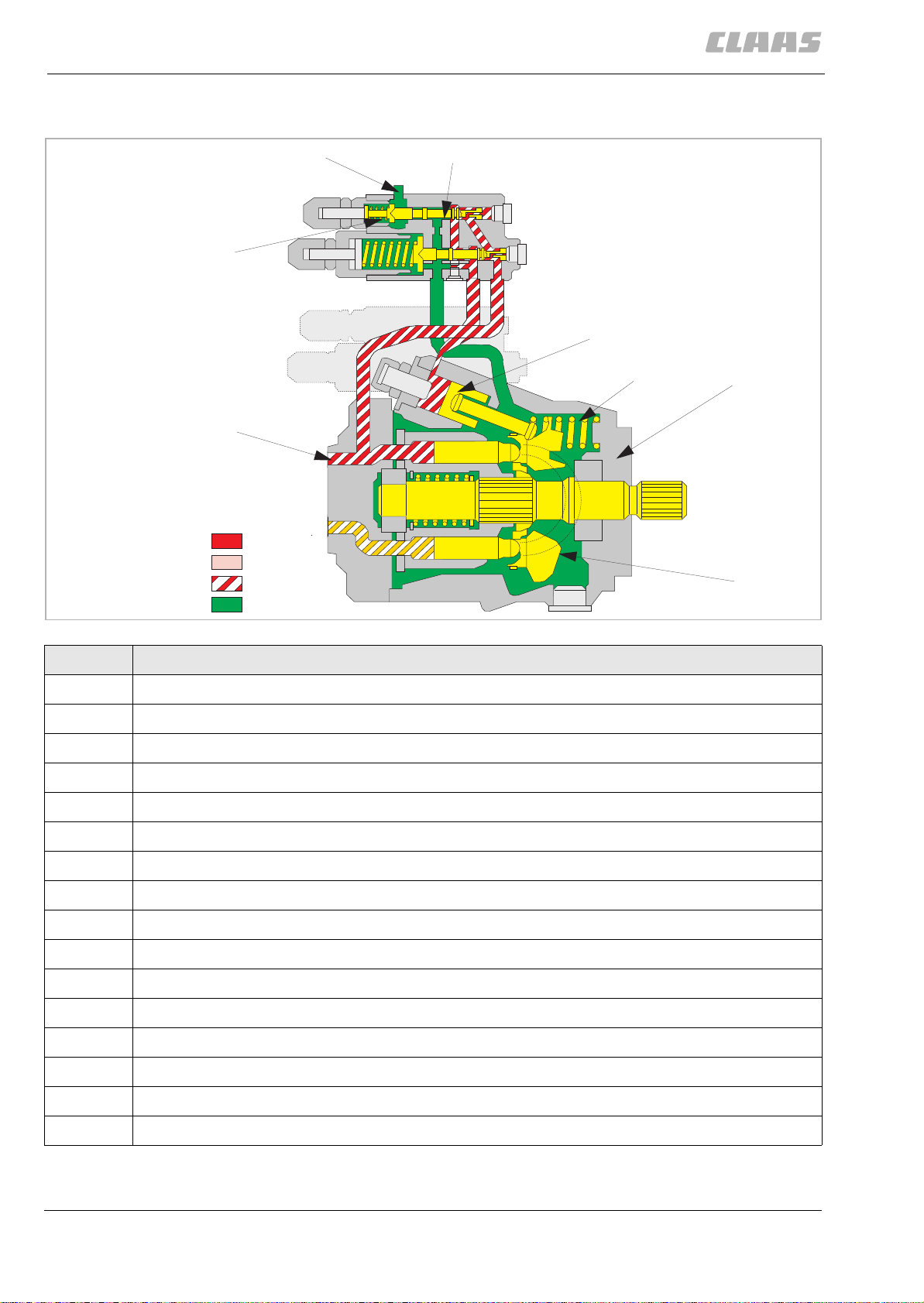
PFC pump
Compensating valve
6
391
772
7
773
AA
13
DD
BB
LL
401482
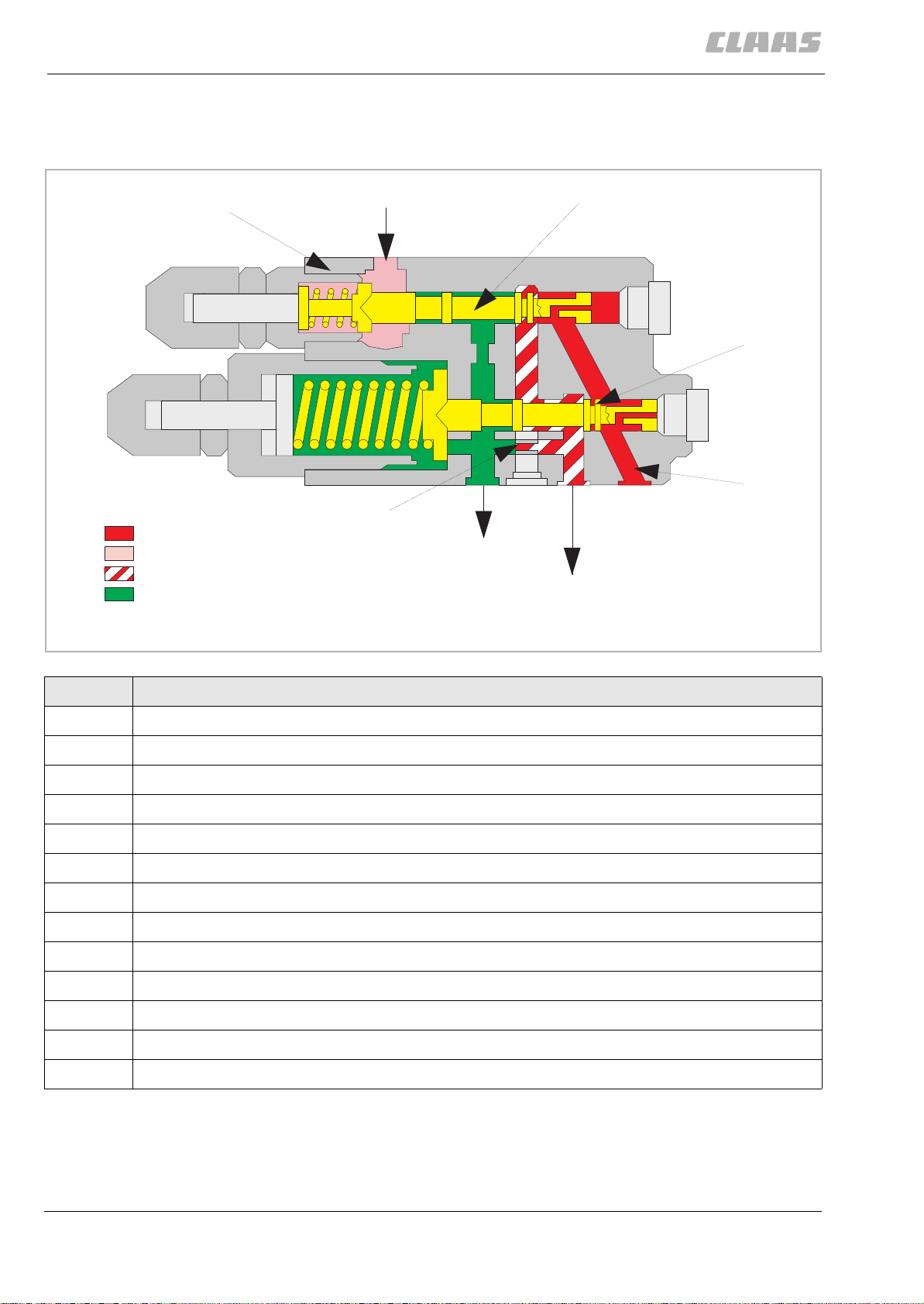
Item Component
6 Compensating valve
7 Input (load pressure from signal network)
10 Working hydraulics pump port
11 Port of control piston of working hydraulics pump
12 Tank port
13 Restrictor
772 Volume flow controller
773 Pressure controller
10
12
11
-AA Oil supply
BB Pressure-reduced oil
DD Control oil
LL Tank (pressureless)
12 000 293 646 0 - SYS-H XERION 3300 - 04/05
Page 13

1 Overall hydraulic system
PFC pump
Description of function The PFC pump (2) is an axial piston pump.
PFC means:
– P (Pressure)
– F (Flow)
– C (Controlled)
PFC pump The compression spring of the volume flow controller (772) is designed so that
the pump pressure acting on the face end is always 20 bar above the load
pressure acting via port (7). This pressure of 20 bar is ref erred to as "Margin
pressure". The pressure controller (773) limit s the pressure in the working
hydraulics circuit to 200±5 bar (Pressure relief valve function).
391
000 293 646 0 - SYS-H XERION 3300 - 04/05 13
Page 14
1 Overall hydraulic system
PFC pump
Initial position (engine OFF)
391
401483
LL
21
20
19
18
7
6
772
377
15
2
16
17
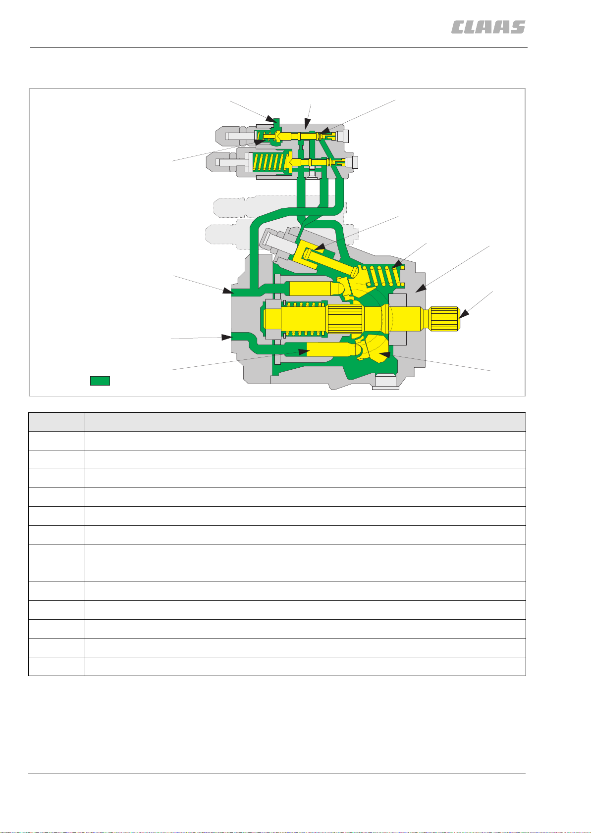
Item Component
2(PFC) Pump
6 Compensating valve
7 Input (load pressure from signal network)
14 Control piston
15 Control spring
16 Pump drive
17 Swash plate
18 Ram
19 Pump inlet
20 Pump outlet
21 Compression spring (margin pressure)
377 Hydraulic cylinder variable-displacement pump
772 Volume flow controller
14 000 293 646 0 - SYS-H XERION 3300 - 04/05
Page 15

1 Overall hydraulic system
PFC pump
Initial position Since the engine has been shut down, there is no pressure in the hydraulic
system. The compression spring (21) has pushed the vol u me flow controller
(772) to the right. In this po sition , the top side of the varia ble-di splaceme nt pump
hydraulic cylinder (37 7) i s conn ec te d wit h th e tank via the volume flow contr oll er
(772). The control spri ng (15) has swi vell ed the swash plat e (17) to its maximum
position.
391
000 293 646 0 - SYS-H XERION 3300 - 04/05 15
Page 16
1 Overall hydraulic system
PFC pump
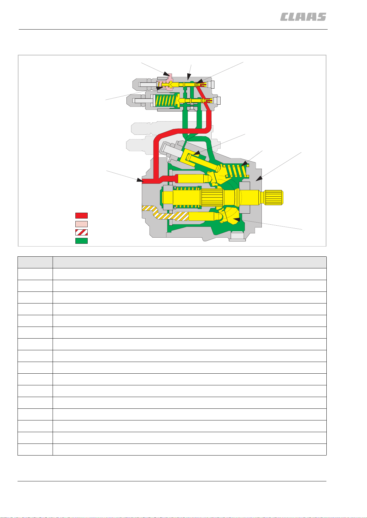
Low-pressure standby
391
401484
21
20
AA
DD
BB
LL
7
772
377
15
2
17
Item Component
2(PFC) Pump
6 Compensating valve
7 Input (load pressure from signal network)
14 Control piston
15 Control spring
17 Swash plate
20 Pump outlet
21 Compression spring (margin pressure)
25 Control edge
377 Hydraulic cylinder variable-displacement pump
772 Volume flow controller
-AA Oil supply
BB Pressure-reduced oil
DD Control oil
LL Tank (pressureless)
16 000 293 646 0 - SYS-H XERION 3300 - 04/05
Page 17

1 Overall hydraulic system
PFC pump
391
Description of function All control units are i n their neutral posi tion. At t he beginnin g of this exa mple, the
swash plate (17) is in its maximum end position (see also Engine OFF).
When the engine is started, the pump feeds the maximum volume flow via the
pump output (20) up to the spools of all control units.
Since the spools block the flow completely, the pr essure rises and is applied to
the right face end of the volume flow controller (772) which is moved to the left
against the compression spring (margin pressure) (21). In this process, the
control edge (25) is opened so that the pressure gains ac cess to the top side of
the variable-displacement pump hydraulic cylinder (377). Now the swash plate
(17) is moved to the "Minimum vo lume flow" position against the control spring
(15). This process takes only 10 milliseconds.
In this pump position, the following happens: Volume flow is generated only to
such an extent that lea kage losses are compensated. The pressure required for
initial actuation of a consum er is ma in tained.
When all control units are set to their neutral positions, the load pres sure input
(7) is pressureless. To move the volume flow controller (772), the pum p pressure
must overcome the compres sion spring (margin pressu re) (21) and the LS
residual pressure. The pressure required for this is 20 + X bar and is referred to
as "Low-pressure standby". The "Low-pressure standby" is slightly higher than
the "Margin pressure" of 20 bar. As a function of the setting of the volume flow
controller (772) and of the pump leakage, "Low-pressure standby" and "Margin
pressure" may be almost i dentical. However, the "Margin pr essure" c an never be
higher. The low-pressure standby cannot be adjusted and may therefore vary
from machine to machine. It changes as the leakage rate i n the pump or in the
system rises. The pump remains in the "Low-pressure standby" position until a
control unit is actuated. In this operating position, the pump only requires little
drive energy.
000 293 646 0 - SYS-H XERION 3300 - 04/05 17
Page 18
1 Overall hydraulic system
PFC pump
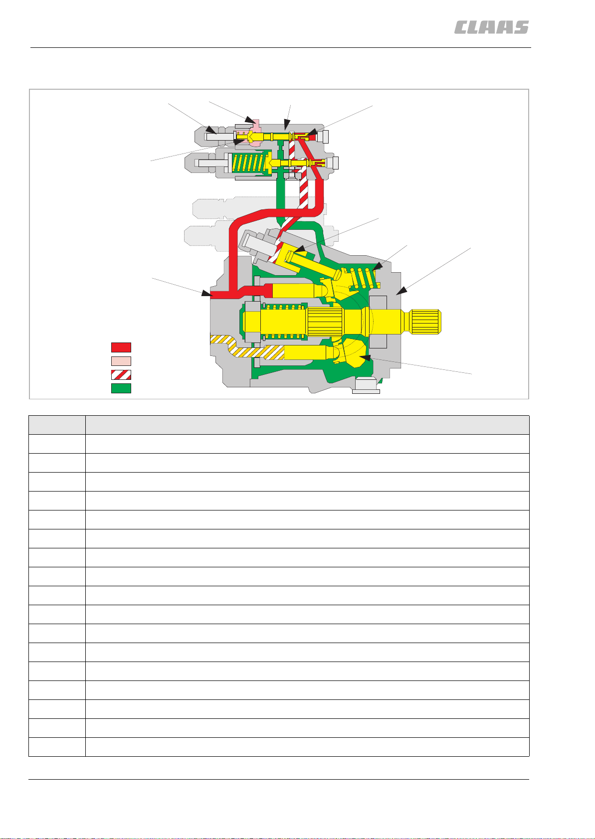
Pump starts pu mping
391
401485
21
20
AA
DD
BB
LL
7
6
772
377
15
2
17
Item Component
2 (PFC) pump
6 Compensating valve
7 Input (load pressure from signal network)
14 Control piston
15 Control spring
17 Swash plate
20 Pump outlet
21 Compression spring (margin pressure)
25 Control edge
377 Variable-displacement pump hydraulic cylinder
772 Volume flow controller
-AA Oil supply
BB Pressure-reduced oil
DD Control oil
LL Tank (pressureless)
18 000 293 646 0 - SYS-H XERION 3300 - 04/05
Page 19

1 Overall hydraulic system
PFC pump
391
Description of function When a control unit is actuated, a load pressure builds up in the LS line. In this
process, the following conditions result at the volume flow controller (772):
– the pump pressure acts on the right face end
– the load pressure and the spring force of the compression spring (margin
pressure) (21) act in the spring space.
– Since the load pressure + the spring force of the compression spring
(margin pressure) (21) is higher than the pump pressure on the right face
end, the volume flow controller is moved to the right .
This :
– shuts off the passage of the pump pressure to the variable-displacement
pump hydraulic cylinder (377);
– connects the variable-displacement pump h ydraulic cylinder (377) wi th the
tank (no pressure on top side of ram)
– makes the control spring (15) swing out the swash plate (17).
The pump now feeds a higher volume flow. This process is referred to as
"Upstroking". The volume flow of the pump is determined by the restrictor effect
of the open spool cross-section or by the setting of a control unit.
Lower volume flow requirement: When the spool cross-section is reduced (the volume flow is to be reduced), the
load pressure at the input (7) drops. This changes the force ratio at the volume
flow controller (772), actuating the volume flow controller to the left according to
the pressure drop, against the compression spring. The variable-displ acement
pump hydraulic cylinder (377) is subject to pressure and the swash plate (17) is
set to a flatter position, and the pump performs a downstroke until the volume
flow requirement is met.
Higher volume flow requirement.
An example: A control unit h as been ac t uat ed. Th e l oa d pr essu re i s 140 ba r, the
pump pressure now goes to (160 bar).(Load pressure 140 bar + 20 bar margin
pressure). When another co nt ro l uni t wi th a l oa d pr ess ure of 100 ba r is actu at ed
now, the pump pressure drops slightly.
This also decreases the pressure on the top face of th e variable-displacement
pump hydraulic cylinder (377) accordingly, the swash plate (17) is moved to a
steeper position, increasing the volume flow until the additional volume flow
requirement of the second circuit has been met and the pump pressure of 160
bar has been re-established. The load pressure on the controller remai ns stable
at 140 bar.
000 293 646 0 - SYS-H XERION 3300 - 04/05 19
Page 20
1 Overall hydraulic system
PFC pump
Constant volume flow
391
401486
21
20
AA
DD
BB
LL
22
7
6
772
377
15
2
17
Item Component
2(PFC) Pump
6 Compensating valve
7 Input (load pressure from signal network)
14 Control piston
15 Control spring
17 Swash plate
20 Pump outlet
21 Compression spring (margin pressure)
22 Setscrew
25 Control edge
377 Variable-displacement pump hydraulic cylinder
772 Volume flow controller
-AA Oil supply
BB Pressure-reduced oil
DD Control oil
LL Tank (pressureless)
20 000 293 646 0 - SYS-H XERION 3300 - 04/05
Page 21

1 Overall hydraulic system
PFC pump
Description of function When operating a consumer with a constant load (e.g. a hydraulic motor), the
volume flow controller (772) is actuated to a stable position. This keeps both the
pressure on the top face of the variable-displacement pump hydraulic cylinder
(377) and the posit ion of the swash plat e (17) co nstant. As long as the positi on of
the swash plate (17) remains unchanged, the pump pumps a constant volume
flow.
The following pressure s now result on the volume flow controller (772):
– Load pressure (signal) + s pring force of the compression spring (margin
pressure) (21) on the left side.
– ·Pump pressure on the right side.
The differential pressure is the margin pressure corresponding to the spring
force of the compression sp ring (21). The margin pressur e is to be 20 bar and
may be adjusted using set screw (22).
391
000 293 646 0 - SYS-H XERION 3300 - 04/05 21
Page 22

1 Overall hydraulic system
PFC pump
Downstroking the PFC pump
391
401487
21
20
AA
DD
BB
LL
7
6
772
377
15
2
17
Item Component
2(PFC) Pump
6 Compensating valve
7 Input (load pressure from signal network)
14 Control piston
15 Control spring
17 Swash plate
20 Pump outlet
21 Compression spring (margin pressure)
22 Setscrew
25 Control edge
377 Variable-displacement pump hydraulic cylinder
772 Volume flow controller
-AA Oil supply
BB Pressure-reduced oil
DD Control oil
LL Tank (pressureless)
22 000 293 646 0 - SYS-H XERION 3300 - 04/05
Page 23

1 Overall hydraulic system
PFC pump
Description of function Downstroking of the PFC pump is performed under the following conditions:
– ·a control unit is actuated to neutral position, no volume flow is required.
– ·an additional contro l unit is actu ated into the fi ne control range, a very sm all
volume flow is required.
– ·in parallel operation, a control unit is actuated to the neutral position or to
the fine control range. A smaller volume flow is required.
The pump must perform a downstroke whenever a smaller volume flow is
needed. The downstroking process is started when the pressure on the right
face end of the volume flow co nt roll e r (7 72) is hi g her tha n on t he le ft face (in the
spring space). In this case, the volume flow controller (772) is moved to the left
against the compressio n spring (21), in this process opening the control edge
(25). This results in a rising pressure on the top face of the variable-displ ace
ment pump hydraulic cylinder (377) that sets the swash plate (17) to a flatter
position against the control spring (15) – the volume flow is reduced.When a
control unit is actuated in the fine control range (a very small volume flow is to
flow to the consumer), the load pressure at input (7) drops. This changes the
force ratio at the volume flow controller (772) so that it is actuated to the left
according to the pressure drop, against the compression spring. The control
edge (25) is opened, thus subjecting the variable-displacement pump hydraulic
cylinder (377) to pressure. The swash plate (17) is se t to a flatter position and
the pump performs a downstroke until the volume flow requirement is met.
391
-
Parallel operation of t wo cont rol
units
When operating two cont rol units in paral lel, the load pressure values are 140
bar and 100 bar. In this process, the pu mp pressure adjusts to 170 bar. (Load
pressure 140 bar + 20 bar margin pressure). Both the volume flow controller
(772) and the swash plate ( 17) are in a co nstant po sition. The pump provid es the
volume flow required for both consumers.When the second control unit (load
pressure 100 bar) is now actuated in the neutral position, the volume flow must
decrease since only the first hydraulic circuit remains to be supplied. This is
achieved by increasing the pump pressure for a short ti me following the shutdown of a hydraulic circuit, since the high volume flow flows to the first control
unit only. The volume flow c ontro l ler ( 772 ) i s n ow a ctuat ed to the left, the control
edge (25) opens and the pressure on the top face of the control ram rises. The
swash plate (17) is set to a flatter position, thus reducing the volume flow.
000 293 646 0 - SYS-H XERION 3300 - 04/05 23
Page 24

1 Overall hydraulic system
PFC pump
Maximum pressure limitation (pressure relief valve function), maximum standby pressure
391
401488
21
23
24
20
AA
DD
BB
LL
7
6
772
773
337
15
2
17
Item Component
2(PFC) Pump
6 Compensating valve
7 Input (load pressure from signal network)
15 Control spring
17 Swash plate
20 Pump outlet
21 Compression spring (margin pressure)
22 Setscrew
26 Control edge
377 Variable-displacement pump hydraulic cylinder
772 Volume flow controller
773 Pressure controller
-AA Oil supply
BB Pressure-reduced oil
DD Control oil
LL Tank (pressureless)
24 000 293 646 0 - SYS-H XERION 3300 - 04/05
Page 25

1 Overall hydraulic system
PFC pump
391
Description of function The pressure in the hydraul ic syst em is li mite d to 200 ± 5 bar in order to pre vent
component damage. This function is ensured by pressure controller (773).During
normal operation (working pressure < max. pressure), the pressure controller
(773) is pushed to the right by compression spring (24). Under such pressure
conditions:
– ·the volume flow controller (772) is pushed to the right by compression
spring (21).
– ·the pressure controller (773) is pushed to the left against compression
spring (24).
This movement occurs at a press ure of 200 ± 5 bar. The control edge (26) is now
opened, enabling the pump pressure to act upon the top face of the variabledisplacement pump hydraulic cylinder (377). The swash plate (17) is now
actuated towards "Min. pump capacity" against the control spring (15). This
takes 8 – 10 milliseconds. The PFC pump now pumps the smallest volume flow
against the maximum pressure of 200 ± 5 bar. The max. pressure can be set
using the set screw (23). The hydraulic system remains at the max. pressure
level until the control unit is actuated in neutral position or until the load on the
LS line is relieved at input (7).
000 293 646 0 - SYS-H XERION 3300 - 04/05 25
Page 26

1 Overall hydraulic system
PFC pump
391
26 000 293 646 0 - SYS-H XERION 3300 - 04/05
Page 27

2 Steering hydraulics
System concept
Description
The vehicle is equipped with an EHL steering system.
EHL is the German abbreviation of "Electro-hydraulic steering".
The electro-hydraulic steering system EHL is an electro-hydraulically controlled,
intelligent automatic steering system for the rigid axle (2).The floating axle (1)
located at the front in direction of travel is steered manually by the steering
wheel as usual. When Autopi lot steering is activated, sensors ensure the
automatic steering of the floating axle (1) along the crop edge. The rigid axle (2)
located at the rear in direction of travel is steered automatically as a function of
the current steering a ngle of the front axle and of the s elected steering strategy.
If required, the "Ground speed control lever" steering strategy also enables
manual steering of the rigid axle (2) independently of the front axle. Both axles
may be steered in order to incre as e ve hic le m an o eu vr a bilit y.
There is a differentiation between the emergenc y steering and Orbitrol steering
of rigid axle (2) or floating axle (1) operating modes. When using the Orbitrol
steering, the floati ng axle (1) is steered entirely by hydraulic means. This ax le is
steered by electro-hydraulic means, but cannot be influenced. At high vehicle
speeds (road travel) the rigid axle (2) is tracked in the straight ahead position .
2 Steering hydraulics
System concept
413
000 293 646 0 - SYS-H XERION 3300 - 04/05 27
Page 28
2 Steering hydraulics
System concept
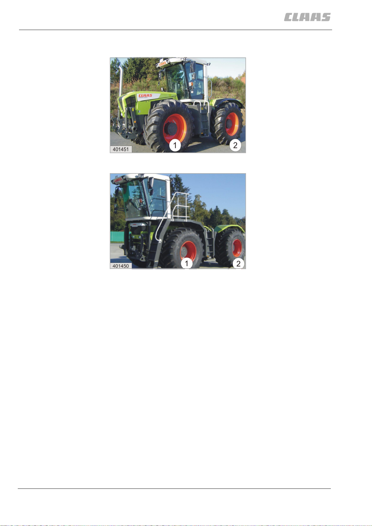
Definition of axles The floating axle (1) is always located below the engine, regardless of the cab
position.
1 = Floating axle 2 = Rigid axle
413
Fully automatic steering operation. Special steering programs
Emergency steering safety
concept
1 = Floating axle 2 = Rigid axle
In the special steering progr am s (e.g . Au to pilo t, cra b stee r mo d e) , th e fr on t an d
the rear axle are steered by electro-hydraulic means. These special steering
programs are available only for fieldwork. Transmission of the steering
commands is fully electronic.
In case of disturbances, the steered axles are brought to a "safe condition". A
"safe condition" is defined as both axles being steered simultaneously and by
purely hydraulic means, using the Orbitrol (steering wheel). To achieve this, the
steering cylinders of the floating axle and of the r igid axle are connected in
series, using the definition valves. The oil supply is ensured by the wheel-driven
emergency steering pump (245). The steering angles of the floating axle and of
the rigid axle are identical, but have their senses reversed.
28 000 293 646 0 - SYS-H XERION 3300 - 04/05
Page 29
Adjusting the straight-l ine
stability of the rigid axle (2).
2 Steering hydraulics
System concept
413
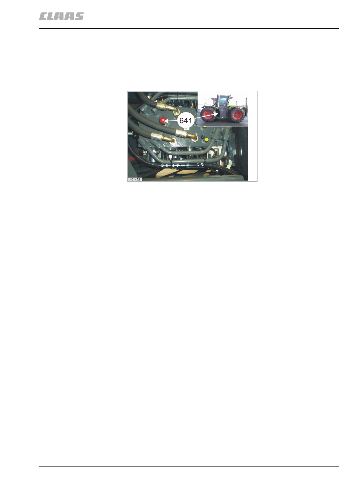
When "Emergency steering operation" is started, the current wheel position of
the rigid axle (2) is adopted . Straight-line stability may no t be pr ov ide d .
In this case:
– Open the shut-off valve (641)
– Set the rigid axle (2) to straight-line travel, using the steering wheel
– Close the shut-off valve (641) again.
000 293 646 0 - SYS-H XERION 3300 - 04/05 29
Page 30

2 Steering hydraulics
System concept
413
30 000 293 646 0 - SYS-H XERION 3300 - 04/05
Page 31

2 Steering hydraulics
Fully hydraulic steering (Emergency steering)
2 Steering hydraulics
Fully hydraulic steering (Emergency steering)
417
000 293 646 0 - SYS-H XERION 3300 - 04/05 31
Page 32

2 Steering hydraulics
Fully hydraulic steering (Emergency steering)
Circuit diagram
30bar
30bar
40bar
40bar
30bar
30bar
408
30bar
30bar
40bar
40bar
417
786
3,5mm
32 000 293 646 0 - SYS-H XERION 3300 - 04/05
Page 33
2 Steering hydraulicsFully hydraulic steering (Emergency steering)
Key to diagram
Item Component
I Main valve block
IX Steering / brake hydraulics pump
-102 Pressure filter
107 Oil drain
112 Return filter
113 Suction filter
116 Resonance tube (Silencer)
117 Fresh air filter element
-218 Steering hydraulics pump
2 Steering hydraulics
Fully hydraulic steering (Emergency steering)
395
245 Emergency steering pump
-323-1 Floating axle steering hydraulic cylinder
323-2 Rigid axle steering hydraulic cylinder
377 Variable-displacement pump hydraulic cylinder
-408 Orifice plate Ø 0.8 m m
-516 Service brake pressure accumulator
-609 Orbitrol steering system rotary valve
641 Shut-off valve
642 Service brake valve
644 Steering sense valve
-704 Bypass valve (non-return valve)
706 Pressure relief valve
725 Steering double shock valve
726 Steering pressure relief valve
732 Non-return valve
742 Steering safety valve
763 Input pressure balance
772 Volume flow controller
000 293 646 0 - SYS-H XERION 3300 - 04/05 33
Page 34

2 Steering hydraulics
Fully hydraulic steering (Emergency steering)
Item Component
772 Volume flow controller
773 Pressure controller
773 Pressure controller
774 Pressurizing valve
780 Shuttle valve
783 Trailer brake valve
786 LS signal shuttle valve
-909-1 Steering hydraulics Orbitrol measuring point
909-2 Steering hydraulics emergency steering pump measur ing point
909-4 Steering hydraulics steering cylinder XS1 measuring point
909-5 Steering hydraulics steering cylinder XS2 measuring point
395
909-6 Steering hydraulics steering cylinder XP2 measuring point
909-7 Steering hydraulics steering cylinder XP1 measuring point
922 Measuring point
-3007 Service brake hydraulic cylinder
3008 Parking brake hydraulic cylinder
-B123 Hydraulic oil temperature sensor
-Y106 Parking brake solenoid coil
Y188-1 Steering logics shut-off valve solenoid coil
Y188-2 Steering logics shut-off valve solenoid coil
Y188-3 Steering logics shut-off valve solenoid coil
Y188-4 Steering logics shut-off valve solenoid coil
Y189-10 Steering logics definition valve solenoid coil
Y189-5 Steering logics definition valve solenoid c oil
Y189-6 Steering logics definition valve solenoid c oil
Y189-7 Steering logics definition valve solenoid c oil
Y189-8 Steering logics definition valve solenoid c oil
Y189-9 Steering logics definition valve solenoid c oil
Y190-1a Automatic steering solenoid coil
Y190-1b Automatic steering solenoid coil
Y190-2a Automatic steering solenoid coil
Y190-2b Automatic steering solenoid coil
34 000 293 646 0 - SYS-H XERION 3300 - 04/05
Page 35

Item Component
Z19 Hydraulic oil level (min.)
Z81 Service brake pressure actual value switch
Z102 Filter bypass actual value switch (bypass open)
Z103 Pump function actual value switch
Z104 Brake accumulator pressure actual value switch
2 Steering hydraulics
Fully hydraulic steering (Emergency steering)
395
000 293 646 0 - SYS-H XERION 3300 - 04/05 35
Page 36

2 Steering hydraulics
Fully hydraulic steering (Emergency steering)
395
36 000 293 646 0 - SYS-H XERION 3300 - 04/05
Page 37

2 Steering hydraulics
Orbitrol axle = Floating axle (1), the rigid axle (2) is tracked by electro-hydraulic means
2 Steering hydraulics
Orbitrol axle = Floating axle (1), the rigid axle (2) is tracked by electro-hydraulic means
397
000 293 646 0 - SYS-H XERION 3300 - 04/05 37
Page 38

2 Steering hydraulics
Orbitrol axle = Floating axle (1), the rigid axle (2) is tracked by electro-hydraulic means
Circuit diagram
408
30bar
397
30bar
40bar
30bar
40bar
786
3,5mm
Xer-h-02a-2
38 000 293 646 0 - SYS-H XERION 3300 - 04/05
Page 39

2 Steering hydraulics
Orbitrol axle = Floatin g axle (1), the rigid axle (2) is tr acked by electro-hydraulic means
2 Steering hydraulics
Orbitrol axle = Floating axle (1), the rigid axle (2) is tracked by electro-hydraulic means
Key to diagram
Item Component
I Main valve block
IX Steering / brake hydraulics pump
-102 Pressure filter
107 Oil drain
112 Return filter
113 Suction filter
116 Resonance tube (Silencer)
117 Fresh air filter element
398
-218 Steering hydraulics pump
245 Emergency steering pump
323-1 Floating axle steering hydraulic cylinder
323-2 Rigid axle steering hydraulic cylinder
377 Variable-displacement pump hydraulic cylinder
-406 Orifice plate
-516 Service brake pressure accumulator
-609 Orbitrol steering system rotary valve
641 Shut-off valve
642 Service brake valve
644 Steering sense valve
-704 Bypass valve (non-return valve)
706 Pressure relief valve
725 Steering double shock valve
726 Steering pressure relief valve
732 Non-return valve
742 Steering safety valve
763 Input pressure balance
772 Volume flow controller
000 293 646 0 - SYS-H XERION 3300 - 04/05 39
Page 40

2 Steering hydraulics
Orbitrol axle = Floating axle (1), the rigid axle (2) is tracked by electro-hydraulic means
Item Component
772 Volume flow controller
773 Pressure controller
773 Pressure controller
774 Pressurizing valve
780 Shuttle valve
783 Trailer brake valve
786 LS signal shuttle valve
-909-1 Steering hydraulics Orbitrol measuring point
909-2 Steering hydraulics emergency steering pump measur ing point
909-4 Steering hydraulics steering cylinder XS1 measuring point
909-5 Steering hydraulics steering cylinder XS2 measuring point
398
909-6 Steering hydraulics steering cylinder XP2 measuring point
909-7 Steering hydraulics steering cylinder XP1 measuring point
-3007 Service brake hydraulic cylinder
3008 Parking brake hydraulic cylinder
-B123 Hydraulic oil temperature sensor
-Y106 Parking brake solenoid coil
Y188-1 Steering logics shut-off valve solenoid coil
Y188-2 Steering logics shut-off valve solenoid coil
Y188-3 Steering logics shut-off valve solenoid coil
Y188-4 Steering logics shut-off valve solenoid coil
Y189-10 Steering logics definition valve solenoid coil
Y189-5 Steering logics definition valve solenoid c oil
Y189-6 Steering logics definition valve solenoid c oil
Y189-7 Steering logics definition valve solenoid c oil
Y189-8 Steering logics definition valve solenoid c oil
Y189-9 Steering logics definition valve solenoid c oil
Y190-1a Automatic steering solenoid coil
Y190-1b Automatic steering solenoid coil
Y190-2a Automatic steering solenoid coil
Y190-2b Automatic steering solenoid coil
Z19 Hydraulic oil level (min.)
40 000 293 646 0 - SYS-H XERION 3300 - 04/05
Page 41

Orbitrol axle = Floatin g axle (1), the rigid axle (2) is tr acked by electro-hydraulic means
Item Component
Z81 Service brake pressure actual value switch
Z102 Filter bypass actual value switch (bypass open)
Z103 Pump function actual value switch
Z104 Brake accumulator pressure actual value switch
2 Steering hydraulics
398
000 293 646 0 - SYS-H XERION 3300 - 04/05 41
Page 42

2 Steering hydraulics
Orbitrol axle = Floating axle (1), the rigid axle (2) is tracked by electro-hydraulic means
398
42 000 293 646 0 - SYS-H XERION 3300 - 04/05
Page 43

2 Steering hydraulics
Orbitrol axle = Rigid axle (2), the floating axle (1) is tracked by electro-hydraulic means
2 Steering hydraulics
Orbitrol axle = Rigid axle (2), the floating axle (1) is tracked by electro-hydraulic means
399
000 293 646 0 - SYS-H XERION 3300 - 04/05 43
Page 44

2 Steering hydraulics
Orbitrol axle = Rigid axle (2), the floating axle (1) is tracked by electro-hydraulic means
Circuit diagram
408
30bar
399
30bar
40bar
30bar
40bar
3,5mm
xer-h-02a-3
44 000 293 646 0 - SYS-H XERION 3300 - 04/05
Page 45

Orbitrol axle = Rigid axle (2), the floating axle (1) is tracked by electro-hydraulic means
2 Steering hydraulicsOrbitrol axle = Rigid axle (2), the floating axle (1) is tracked by electro-hydraulic means
Key to diagram
Item Component
I Main valve block
IX Steering / brake hydraulics pump
-102 Pressure filter
107 Oil drain
112 Return filter
113 Suction filter
116 Resonance tube (Silencer)
117 Fresh air filter element
-218 Steering hydraulics pump
2 Steering hydraulics
400
245 Emergency steering pump
-323-1 Floating axle steering hydraulic cylinder
323-2 Rigid axle steering hydraulic cylinder
377 Variable-displacement pump hydraulic cylinder
-408 Orifice plate Ø 0.8 m m
-516 Service brake pressure accumulator
-609 Orbitrol steering system rotary valve
641 Shut-off valve
642 Service brake valve
644 Steering sense valve
-704 Bypass valve (non-return valve)
706 Pressure relief valve
725 Steering double shock valve
726 Steering pressure relief valve
732 Non-return valve
742 Steering safety valve
763 Input pressure balance
772 Volume flow controller
000 293 646 0 - SYS-H XERION 3300 - 04/05 45
Page 46

2 Steering hydraulics
Orbitrol axle = Rigid axle (2), the floating axle (1) is tracked by electro-hydraulic means
Item Component
772 Volume flow controller
773 Pressure controller
773 Pressure controller
774 Pressurizing valve
780 Shuttle valve
783 Trailer brake valve
786 LS signal shuttle valve
-909-1 Steering hydraulics Orbitrol measuring point
909-2 Steering hydraulics emergency steering pump measur ing point
909-4 Steering hydraulics steering cylinder XS1 measuring point
909-5 Steering hydraulics steering cylinder XS2 measuring point
400
909-6 Steering hydraulics steering cylinder XP2 measuring point
909-7 Steering hydraulics steering cylinder XP1 measuring point
922 Measuring point
-3007 Service brake hydraulic cylinder
3008 Parking brake hydraulic cylinder
-B123 Hydraulic oil temperature sensor
-Y106 Parking brake solenoid coil
Y188-1 Steering logics shut-off valve solenoid coil
Y188-2 Steering logics shut-off valve solenoid coil
Y188-3 Steering logics shut-off valve solenoid coil
Y188-4 Steering logics shut-off valve solenoid coil
Y189-10 Steering logics definition valve solenoid coil
Y189-5 Steering logics definition valve solenoid c oil
Y189-6 Steering logics definition valve solenoid c oil
Y189-7 Steering logics definition valve solenoid c oil
Y189-8 Steering logics definition valve solenoid c oil
Y189-9 Steering logics definition valve solenoid c oil
Y190-1a Automatic steering solenoid coil
Y190-1b Automatic steering solenoid coil
Y190-2a Automatic steering solenoid coil
Y190-2b Automatic steering solenoid coil
46 000 293 646 0 - SYS-H XERION 3300 - 04/05
Page 47

Orbitrol axle = Rigid axle (2), the floating axle (1) is tracked by electro-hydraulic means
Item Component
Z19 Hydraulic oil level (min.)
Z81 Service brake pressure actual value switch
Z102 Filter bypass actual value switch (bypass open)
Z103 Pump function actual value switch
Z104 Brake accumulator pressure actual value switch
2 Steering hydraulics
400
000 293 646 0 - SYS-H XERION 3300 - 04/05 47
Page 48

2 Steering hydraulics
Orbitrol axle = Rigid axle (2), the floating axle (1) is tracked by electro-hydraulic means
400
48 000 293 646 0 - SYS-H XERION 3300 - 04/05
Page 49

2 Steering hydraulics
The floating axle (1) and the rigid axle (2) are steered electrohydraulically – the Orbitrol steering circuit is closed.
2 Steering hydraulics
The floating axle (1) and the rigid axle (2) are steered electro-hydraulically – the Orbitrol steering circ uit is closed.
401
000 293 646 0 - SYS-H XERION 3300 - 04/05 49
Page 50

2 Steering hydraulics
The floating axle (1) and the rigid axle (2) are steered el ectro-hydraulically – the Orbitrol steering circuit is closed.
Circuit diagram
408
30bar
401
30bar
40bar
30bar
40bar
786
3,5mm
xer-h-02a-4
50 000 293 646 0 - SYS-H XERION 3300 - 04/05
Page 51

2 Steering hydraulics
The floating axle (1) and t he rigid axle (2) are steered electro-hydraulically – t he Orbitrol steering circuit is closed.
2 Steering hydraulicsThe floating axle (1) and the rigid axle (2) are steered electro-hydraulica lly – the Orbitrol steering circuit is closed.
Key to diagram
Item Component
I Main valve block
IX Steering / brake hydraulics pump
-102 Pressure filter
107 Oil drain
112 Return filter
113 Suction filter
116 Resonance tube (Silencer)
117 Fresh air filter element
-218 Steering hydraulics pump
402
245 Emergency steering pump
-323-1 Floating axle steering hydraulic cylinder
323-2 Rigid axle steering hydraulic cylinder
377 Variable-displacement pump hydraulic cylinder
-408 Orifice plate Ø 0.8 m m
-516 Service brake pressure accumulator
-609 Orbitrol steering system rotary valve
641 Shut-off valve
642 Service brake valve
644 Steering sense valve
-704 Bypass valve (non-return valve)
706 Pressure relief valve
725 Steering double shock valve
726 Steering pressure relief valve
732 Non-return valve
742 Steering safety valve
763 Input pressure balance
772 Volume flow controller
000 293 646 0 - SYS-H XERION 3300 - 04/05 51
Page 52

2 Steering hydraulics
The floating axle (1) and the rigid axle (2) are steered el ectro-hydraulically – the Orbitrol steering circuit is closed.
Item Component
772 Volume flow controller
773 Pressure controller
773 Pressure controller
774 Pressurizing valve
780 Shuttle valve
783 Trailer brake valve
786 LS signal shuttle valve
-909-1 Steering hydraulics Orbitrol measuring point
909-2 Steering hydraulics emergency steering pump measur ing point
909-4 Steering hydraulics steering cylinder XS1 measuring point
909-5 Steering hydraulics steering cylinder XS2 measuring point
402
909-6 Steering hydraulics steering cylinder XP2 measuring point
909-7 Steering hydraulics steering cylinder XP1 measuring point
922 Measuring point
-3007 Service brake hydraulic cylinder
3008 Parking brake hydraulic cylinder
-B123 Hydraulic oil temperature sensor
-Y106 Parking brake solenoid coil
Y188-1 Steering logics shut-off valve solenoid coil
Y188-2 Steering logics shut-off valve solenoid coil
Y188-3 Steering logics shut-off valve solenoid coil
Y188-4 Steering logics shut-off valve solenoid coil
Y189-10 Steering logics definition valve solenoid coil
Y189-5 Steering logics definition valve solenoid c oil
Y189-6 Steering logics definition valve solenoid c oil
Y189-7 Steering logics definition valve solenoid c oil
Y189-8 Steering logics definition valve solenoid c oil
Y189-9 Steering logics definition valve solenoid c oil
Y190-1a Automatic steering solenoid coil
Y190-1b Automatic steering solenoid coil
Y190-2a Automatic steering solenoid coil
Y190-2b Automatic steering solenoid coil
52 000 293 646 0 - SYS-H XERION 3300 - 04/05
Page 53

2 Steering hydraulics
The floating axle (1) and t he rigid axle (2) are steered electro-hydraulically – t he Orbitrol steering circuit is closed.
402
Item Component
Z19 Hydraulic oil level (min.)
Z81 Service brake pressure actual value switch
Z102 Filter bypass actual value switch (bypass open)
Z103 Pump function actual value switch
Z104 Brake accumulator pressure actual value switch
000 293 646 0 - SYS-H XERION 3300 - 04/05 53
Page 54

2 Steering hydraulics
The floating axle (1) and the rigid axle (2) are steered el ectro-hydraulically – the Orbitrol steering circuit is closed.
402
54 000 293 646 0 - SYS-H XERION 3300 - 04/05
Page 55

2 Steering hydraulics
Steering valve VI
2 Steering hydraulics
Steering valve VI
403
000 293 646 0 - SYS-H XERION 3300 - 04/05 55
Page 56

2 Steering hydraulics
Steering valve VI
Graphics
403
Y190-1a
Y190-2a
3.1A
3.1B
3.1
VI
909-2(XP-NLP)
909-1(XP-Orb)
3.2A
Y190-1b
Y190-2b
772
3.2B
P-Orb
706
LS
AR/R
3.2A 3.1A
BL/L
Y188-10(DV10)
Y188-8(DV8)
641(1.11)
909-7(P1)
3.2B
3.1B
909-6(P2)
3.1A
3.2A
Y188-2(DV2)
Y188-3(DV3)
Y188-9(DV9)
909-3(XP-BR)
400995
NLP
VP
BR
XP-ZLP
ZLP
T
725-2
Z103
Y189-7(DV7)
19.0
Y189-6(DV6)
725-1
S2
S1
Y189-5(DV5)
909-5(S2)
P2
909-4(XP1)
P1
Y188-4(DV4)
Y188-1(DV1)
3,5mm
56 000 293 646 0 - SYS-H XERION 3300 - 04/05
Page 57

2 Steering hydraulicsSteering valve VI
Key to diagram
Item Component
VI Steering valve
-116 Resonance tube (Silencer)
-245 Emergency steering pump
-641 Shut-off valve
-706 Pressure relief valve
725 Steering double shock valve
726 Steering pressure relief valve
2 Steering hydraulics
Steering valve VI
404
732 Non-return valve
763 Input pressure balance
768 LS signal shuttle valve
772 Volume flow controller
774 Pressurizing valve
-909-1 Steering hydraulics Orbitrol measuring point
909-2 Steering hydraulics emergency steering pump measuri ng point
909-3 Steering hydraulics system pressure (steering/brake) measuring point
909-4 Steering hydraulics steering cylinder XS1 measuring point
909-5 Steering hydraulics steering cylinder XS2 measuring point
909-6 Steering hydraulics steering cylinder XP2 measuring point
909-7 Steering hydraulics steering cylinder XP1 measuring point
-Y188-1 Steering logics shut-off valve solenoid coil
Y188-2 Steering logics shut-off valve solenoid coil
Y188-3 Steering logics shut-off valve solenoid coil
Y188-4 Steering logics shut-off valve solenoid coil
Y189-5 Steering logics definit ion valve solenoid coil
Y189-6 Steering logics definit ion valve solenoid coil
Y189-7 Steering logics definit ion valve solenoid coil
Y189-8 Steering logics definit ion valve solenoid coil
Y189-9 Steering logics definit ion valve solenoid coil
000 293 646 0 - SYS-H XERION 3300 - 04/05 57
Page 58

2 Steering hydraulics
Steering valve VI
Item Component
Y189-10 Steering logics definition valve solenoid coil
Y190-1a Automatic steering solenoid coil
Y190-1b Automatic steering solenoid coil
Y190-2a Automatic steering solenoid coil
Y190-2b Automatic steering solenoid coil
404
58 000 293 646 0 - SYS-H XERION 3300 - 04/05
Page 59

3 Working hydraulics
Working hydraulics circuit diagram
3 Working hydraulics
Working hydraulics circuit diagram
405
000 293 646 0 - SYS-H XERION 3300 - 04/05 59
Page 60

3 Working hydraulics
Working hydraulics circuit diagram
Circuit diagram
405
50bar
100bar
XP-PA
60 000 293 646 0 - SYS-H XERION 3300 - 04/05
Page 61

3 Working hydraulicsWorking hydraulics circuit diagram
Key to diagram
Item Component
I Main valve block
-102-1 Working hydraulics pressure filter
-515 Pressure accumulator
-704 Bypass valve (non-return valve)
706 Pressure relief valve
768 LS signal shuttle valve
772-1a Volume flow controller (red A)
772-1b Volume flow controller (red B)
3 Working hydraulics
Working hydraulics circuit diagram
406
772-2a Volume flow controller (EHR A)
772-2b Volume flow controller (EHR B)
772-3a Volume flow controller (white A)
772-3b Volume flow controller (white B)
772-4a Volume flow controller (yellow A)
772-4b Volume flow controller (yellow B)
772-5a Volume flow controller (green A)
772-5b Volume flow controller (green B)
772-6a Volume flow controller (swing lower link A)
772-6b Volume flow controller (swing lower link B)
787 Pressure balance
-901 Working hydraulics measuring point
-Y121 Shifting aid, reverse
Y192 Floating axle locking solenoid valve
Y193 Floating axle unlocking solenoid valve
Y198-1a Pilot valve (red A)
Y198-1b Pilot valve (red B)
Y198-2a Pilot valve (EHR A)
Y198-2b Pilot valve (EHR B)
Y198-3a Pilot valve (white A)
Y198-3b Pilot valve (white B)
000 293 646 0 - SYS-H XERION 3300 - 04/05 61
Page 62
3 Working hydraulics
Working hydraulics circuit diagram
Item Component
Y198-4a Pilot valve (yellow A)
Y198-4b Pilot valve (yellow B)
Y198-5a Pilot valve (green A)
Y198-5b Pilot valve (green B)
Y198-6a Pilot valve (blue A)
Y198-6b Pilot valve (blue B)
-Z102-1 Working hydraulics filter bypass actual value switch (bypass open)
Z105-1 Floating axle lock 55 bar pres sure
Z105-2 Floating axle lock 115 bar pressure
406
62 000 293 646 0 - SYS-H XERION 3300 - 04/05
Page 63

3 Working hydraulics
Main valve block
3 Working hydraulics
Main valve block
407
000 293 646 0 - SYS-H XERION 3300 - 04/05 63
Page 64

3 Working hydraulics
Main valve block
Graphics
XP-L
Z102-2
XP-A
515 (40 bar)
515 (80 bar)
515 (40 bar)
515 (40 bar)
515 (80 bar)
901
(XP-A)
Z102-1 Z102-2
909-3
(XP-L)
LS
407
XP-T-Orb
Z102-1
Y192 Y121 Y193
Z105-1 Z105-2
706
XP-PA
20.1
20.2
20.3
20.4
20.5
102-1
924
(XP-LS)
924
(XP-T)
102-2
785 421
20.6 20.5 20.4 20.3 20.2 20.1
401003
64 000 293 646 0 - SYS-H XERION 3300 - 04/05
Page 65

3 Working hydraulicsMain valve block
Key to diagram
Item Component
I Main valve block
-102-1 Working hydraulics pressure filter
-515 Pressure accumulator
-704 Bypass valve (non-return valve)
706 Pressure relief valve
768 LS signal shuttle valve
772-1a Volume flow controller (red A)
772-1b Volume flow controller (red B)
3 Working hydraulics
Main valve block
408
772-2a Volume flow controller (EHR A)
772-2b Volume flow controller (EHR B)
772-3a Volume flow controller (white A)
772-3b Volume flow controller (white B)
772-4a Volume flow controller (yellow A)
772-4b Volume flow controller (yellow B)
772-5a Volume flow controller (green A)
772-5b Volume flow controller (green B)
772-6a Volume flow controller (swing lower link A)
772-6b Volume flow controller (swing lower link B)
787 Pressure balance
-901 Working hydraulics measuring point
924 LS pressure measuring point
-Y121 Shifting aid, reverse
Y192 Floating axle locking solenoid valve
Y193 Floating axle unlocking solenoid valve
Y198-1a Pilot valve (red A)
Y198-1b Pilot valve (red B)
Y198-2a Pilot valve (EHR A)
Y198-2b Pilot valve (EHR B)
Y198-3a Pilot valve (white A)
000 293 646 0 - SYS-H XERION 3300 - 04/05 65
Page 66

3 Working hydraulics
Main valve block
Item Component
Y198-3b Pilot valve (white B)
Y198-4a Pilot valve (yellow A)
Y198-4b Pilot valve (yellow B)
Y198-5a Pilot valve (green A)
Y198-5b Pilot valve (green B)
Y198-6a Pilot valve (blue A)
Y198-6b Pilot valve (blue B)
-Z102-1 Working hydraulics filter bypass actual value switch (bypass open)
Z105-1 Floating axle lock 55 bar pres sure
Z105-2 Floating axle lock 115 bar pressure
408
66 000 293 646 0 - SYS-H XERION 3300 - 04/05
Page 67

Following the policy of CLAAS KGaA mbH to improve
their products as technical developments continue,
CLAAS reserve the right to make alterations which
must not necessarily corr es po n d to tex t an d illus tr a
tions contained in this publication, and without
incurring obligation to alter any machines previously
delivered.Technical data, dimensions and weights are
given as an indication only. Responsibility for errors
and omissions not accepted. Reproduction or transla
tion of this publication, in whole or in part, is not
permitted without the wri tt en c onsen t of CL AAS KGaA
mbH.All rights under th e provisi on of the Copyrig ht Act
are reserved. CLAAS KGaA mbH33426
HARSEWINKEL Germany
411
-
Our contribution to the environment:CLAAS
have printed this manual on 100% chlorine
free paper.
Page 68

CLAAS KGaA mbH
Postfach 1163
33426 Harsewinkel
Tel. +49 (0)5247 12-0
www.claas.com
000 293 646 0
SYS-H XERION 3300
EN - 04/05
Printed in Germany
 Loading...