

Claas Targo K50, Targo K60, Targo K70 Repair Manual

HYDRAULICS
ELECTRICS
TECHNICAL DATA
CLCL
CL
CLCL
AA
AS TAS T
A
AS T
AA
AS TAS T
ARGO K50 K60 K70ARGO K50 K60 K70
ARGO K50 K60 K70
ARGO K50 K60 K70ARGO K50 K60 K70

The machines in this handbook are designed essentially for agricultural and associated applications. This is
their intended use.
Any modifications made to the machine without prior written approval from CLAAS or if the machine is used
in any way contrary to the intended use or if the machine is not properly driven or maintained then the
Company will not accept any liability whatsoever for any damage or injury (whether direct or consequential).
The method of operation and maintenance specified in this handbook should be strictly adhered to.
For your parts requirements, it is essential that only genuine CLAAS parts are fitted. Any resultant damage
from non-genuine parts will invalidate your machine warranty.
CLAAS operates a policy of continuous improvement to its products and reserve the right to change specifi-
cations and equipment without notice. Therefore some information within this handbook may differ from your
machine.
This manual is designed to service machines:
from Serial No. 51200011
up to Serial No. 51200727.
from Serial No. K5D00100
from Serial No. K6D00100
from Serial No. K7D00100

CONTENTS
INTRODUCTION
General
Machine identification
Health and Safety
SAFETY WARNINGS
SECTION 1
HYDRAULICS
Description and Operation 1.1
Description 1.1
General 1.1
Dumping (dissipation) of hydraulic pressure 1.1
To dump brake system pressure 1.1
To dump a system pressure 1.1
Hydraulic Circuit - Single Circuit Braking (up to Machines S/No.51200317) 1.2
Hydraulic Circuit - Single Circuit Braking (from Machines S/No.51200318 to 51200471) 1.4
Hydraulic Circuit - Single Circuit Braking (from Machines S/No.51200472 to 51200551) 1.6
Hydraulic Circuit - Single Circuit Braking (from Machines S/No.51200552 to 51200727) 1.8
Hydraulic Circuit - Dual Circuit Braking (up to Machines S/No.51200317) 1.10
Hydraulic Circuit - Dual Circuit Braking (from Machines S/No.51200318 to 51200471) 1.12
Hydraulic Circuit - Dual Circuit Braking (from Machines S/No.51200472 to 51200551) 1.14
Hydraulic Circuit - Dual Circuit Braking (from Machines S/No.51200552 to 51200727) 1.16
Components
General 1.18
Hydraulic tank 1.18
Suction line connections to hydraulic tank 1.18
Return hose connections to hydraulic tank (up to Machines S/No.51200471) 1.18
Return hose connections to hydraulic tank (from Machines S/No.51200472) 1.18
Hydraulic pump (load sensing) 1.19
Pump compensator (load sensing) 1.19
Tank filter 1.19
Filler/Breather 1.19
Auxiliary hydraulic pump 1.19
Fan motor (up to Machines S/No.51200471) 1.20
Fan reverse motor (from Machines S/No.51200472) 1.20
Pressure reducing valve (PRV) for the parking brake (up to Machines S/No.51200551) 1.21
Pressure filter 1.21
Single circuit brake pressure servo valve (MICO) (up to Machines S/No.51200471) 1.22
Duel circuit brake pressure servo valve (MICO) (up to Machines S/No.51200471) 1.22
Single circuit brake pressure servo valve (SAFIM) (from Machines S/No.51200472) 1.23
Duel circuit brake pressure servo valve (SAFIN) (from Machines S/No.51200472) 1.23
Accumulator(s) 1.24
Pressure switch 1.24
Pressure switch (transmission dump) 1.24
Front axle 1.25
Steering cylinder (front) 1.25
Pressure switch (brake light) 1.25
Pressure switch (parking brake) 1.26
Rear axle 1.26
Steering cylinder (rear) 1.26
Non-return valve 1.26
Steering valve 1.27
Steering in Neutral position 1.27
Steering in Operation 1.28
Pressure relief valve 1.28
Steering selector valve 1.29

CONTENTS
Components (continued)
Control valve 1.30
Outlet section (PVP) 1.31
Function 1.31
Extension section 1.32
Function 1.32
Crowd section 1.33
Function 1.33
Lift section 1.34
Function 1.34
1st service/2nd service section 1.35
Function 1.35
Inlet section (PVSP) section 1.36
Function 1.36
Accumulator 1.38
Tap 1.38
Trailer brake valve 1.38
Trailer brake coupling 1.38
Extension cylinder 1.39
Load control valve 1.39
Crowd cylinder 1.40
Load control valve 1.40
Compensator cylinder 1.41
Lift cylinder 1.41
Load control valve 1.42
Diverter valve 1.43
Manifold 1.43
Autohitch cylinder 1.44
1st service couplings 1.44
2nd service couplings 1.44
Trailer tipping connection 1.44
St art-up valve 1.44
Non-return valve (up to Machine S/No.51200317 only) 1.45
Pressure relief valve (up to Machine S/No.51200471 only) 1.45
Breather 1.45
Parking brake valve (from Machine S/No.51200552 only) 1.46
Fan reverse valve (from Machine S/No.51200472 only) 1.47
Oil cooler (from Machine S/No.51200472 only) 1.48
Operation 1.49
General 1.49
Relief valves 1.49
System pressure checks 1.50
LS pump 1.52
LS pump compensator operation 1.52
Standby position (engine switched off) 1.53
Standby position (engine started) 1.54
Pump goes into delivery 1.56
Constant volumetric flow 1.58
Downstroking of the pump 1.59
Maximum pressure limiting (pressure relief valve function) 1.45
Adjusting the pump 1.63

CONTENTS
Maintenance 1.64
Torque tightening 1.64
Hydraulic level 1.66
Check 1.66
Hydraulic tank 1.67
Removal 1.67
Installation 1.67
Hydraulic pump (LS) 1.68
Removal 1.68
Installation 1.68
Auxiliary hydraulic pump 1.69
Removal 1.69
Installation 1.69
Fan motor (up to Machines S/No.51200471 only) 1.70
Removal 1.70
Installation 1.70
Fan motor bearings (up to Machines S/No.51200471 only) 1.71
Removal 1.71
Installation 1.71
Fan motor (from Machines S/No.51200472 only) 1.72
Removal 1.72
Installation 1.72
Fan drive bearings (from Machines S/No.51200472 only) 1.73
Removal 1.73
Installation 1.73
Fan reverse valve (from Machines S/No.51200472 only) 1.74
Removal 1.74
Installation 1.74
Parking brake valve (from Machines S/No.51200472 only) 1.75
Removal 1.75
Installation 1.75
Hydraulic filter 1.76
Removal 1.76
Installation 1.76
Brake valve (MICO) (up to Machines S/No.51200471 only) 1.77
Operation 1.77
Brake valve (SAFIM) (from Machines S/No.51200472 only) 1.77
Operation 1.77
Single brake valve (MICO) (up to Machines S/No.51200471 only) 1.78
Removal 1.78
Installation 1.78
Servicing 1.79
Dismantling 1.79
Assembly 1.80
Single brake valve (SAFIM) (from Machines S/No.51200472 only) 1.81
Removal 1.81
Installation 1.81
Servicing 1.82
Dismantling (General) 1.82
Assembly (General) 1.82
Dismantling (Brake master module) 1.83
Assembly (Brake master module) 1.83
Dismantling (Brake valve module) 1.84
Assembly (Brake valve module) 1.84

CONTENTS
Dual brake valve (MICO) (up to Machines S/No.51200471 only) 1.85
Removal 1.85
Installation 1.85
Servicing 1.86
Dismantling 1.86
Assembly 1.88
Dual brake valve (SAFIM) (from Machines S/No.51200472 only) 1.89
Removal 1.89
Installation 1.89
Servicing 1.90
Removal and installation (General) 1.90
Dismantling (Brake master module) 1.90
Assembly (Brake master module) 1.90
Dismantling (Brake valve module) 1.91
Assembly (Brake valve module) 1.91
Trailer brake valve 1.92
Removal 1.92
Installation 1.92
Servicing 1.93
Dismantling 1.93
Assembly 1.94
Brake system bleeding 1.95
General 1.95
Diverter valve 1.96
Removal 1.96
Installation 1.96
Manifold 1.97
Removal 1.97
Installation 1.97
Control valve 1.98
Removal 1.98
Installation 1.98
Servicing 1.99
Dismantling 1.99
Assembly 1.99
Spool sections 1.101
General 1.101
Dismantling 1.101
Assembly 1.101
Inlet section (PVSP) 1.103
General 1.103
Dismantling 1.103
Assembly 1.103
Outlet section (PVP) 1.104
General 1.104
Dismantling 1.104
Assembly 1.104
Steering 1.105
Description 1.105
Operation 1.105
Checking the steering system 1.107
Steering cylinder 1.107
Steering unit (OSPF) 1.107
Servicing 1.107
Steering valve assembly 1.108
Removal 1.108
Installation 1.108
Servicing 1.109
Dismantling 1.109
Assembly 1.109

CONTENTS
Hydraulic cylinders 1.110
Extension cylinder 1.110
Removal 1.110
Installation 1.111
Crowd cylinder 1.112
Removal 1.112
Installation 1.112
Compensator cylinder 1.113
Removal 1.113
Installation 1.113
Lift cylinder 1.114
Removal 1.114
Installation 1.114
Extension, crowd, compensator and lift cylinder 1.115
Servicing 1.115
Dismantling 1.115
Assembly 1.115
Autohitch cylinder 1.117
Removal 1.117
Installation 1.117
Dismantling 1.117
Assembly 1.118
Carriage locking cylinder 1.119
Removal 1.119
Installation 1.119
Dismantling 1.119
Assembly 1.120
Steering cylinder 1.121
Removal 1.121
Installation 1.121
Dismantling 1.122
Assembly 1.122
SECTION 2
ELECTRICS
Circuit diagrams
Circuit diagram key - Wiring terminations 2.1
Circuit diagram key - Components 2.2
Circuit diagram key - General Information 2.4
Power generation, S tarting, Non APC (Sheet 1) 2.4
Power generation, Starting, With APC (Sheet 1A) 2.5
Hydraulic controls, Steering control, Safe load indicator , Large lock out relay (Sheet 2) 2.6
Hydraulic controls, Steering control, Safe load indicator , Mini lock out relay (Sheet 2A) 2.7
Wipers, Washers, Horn, Worklights (Sheet 3) 2. 8
Wipers, Washers, Horn, Worklights combined boom/side worklights, Switching (Sheet 3A) 2.9
Head/side lights, Fog lights, Number plate lights, Head Flasher (Sheet 4) 2.10
Head/side lights, Fog lights, Number plate lights, Head Flasher (Sheet 4A) 2.11
Turn indicators, Reverse lamps, S teer sensors, S top lights, Radio (Sheet 5) 2.12
Inst display , Sensor switches, Fan motor , Aircon, Interior light, Beacon, Fuel Sender ,
Fan reverse, Hydraulic temp. (Sheet 6) 2.13
APC 50 with Ign controlled APC bat feed, Screened sensor cable, P/brake link (Sheet 7) 2.14
Non APC,Correct P/brake and trans dump, No P/brake controller , Circuit link (Sheet 7A) 2.15
Chassis loom (Illustration) 2.16
Engine loom (Illustration) 2.17
Cab loom (Illustration) 2.18

CONTENTS
Longitudinal stability indicator 2.19
Description 2.19
Sensor 2.20
Specification 2.20
Display Module 2.20
Specification 2.20
Testing and adjustment 2.23
Troubleshooting 2.23
Visual inspection 2.23
System check 2.24
Error indications from the display module 2.25
Sensor - test 2.25
General 2.25
Procedure to test the operation of the sensor 2.26
Procedure to install a sensor 2.27
Procedure to replace the display module 2.28
Calibration 2.29
Calibration procedure 2.29
Resetting the zero point 2.31
Testing load sensor function 2.32
Functional test of load sensor indicator 2.32
Procedure 2.33
Main instrument panel 2.34
Description 2.34
Removal 2.34
Installation 2.34
Functional description 2.35
Solo control joystick 2.36
Removal 2.36
Installation 2.36
Starter 2.37
Removal 2.37
Installation 2.37
Fusebox and relays 2.38
Description 2.38
Removal 2.38
Installation 2.38
Alternator 2.40
Alternator drive belt check 2.40
Removal 2.41
Installation 2.41
Automatic powershift 2.42
Automatic powershift controller 2.42
Removal 2.42
Installation 2.42
Forward / Neutral / Reverse (FNR) switch assembly 2.43
Removal 2.43
Installation 2.43

CONTENTS
SECTION 3
TECHNICAL DATA
Dimensions 3.1
Performance 3.2
Machine speed (km/hr) for 106 hp 3.2
Carriage 3.3
Cycle time 3.3
Engine 3.4
Cooling 3.4
Transmission 3.4
Tyres 3.4
Hydraulics 3.5
Electrics 3.5
Capacities 3.5
INTRODUCTION
General
The contents of this Repair Manual, although correct at the time of publication, may be subject to alteration
by the manufacturer without notice.
This manual assumes that maintenance personnel have a sound knowledge of workshop practices and
safety procedures associated with the repairs of this type of machine. This manual is designed to assist with
the more specialised information required for removal and strip-down of major components.
It is recommended that the relevant part of this Repair Manual is studied carefully before proceeding with
any maintenance.
Machine identification
To make sure that the correct parts are obtained, always quote the machine Serial Number when ordering
parts.
Health and Safety
To prevent injury to personnel and damage to equipment and machinery, care must be taken to operate in a
safe manner. Read the Safety Warnings that follow and always work in a safe manner and obey the relevant
Warnings.
Throughout this manual and on the machine there are safety notes. Each note starts with a single word. The
meaning of these single words is as follows:
Identifies a hazard exists. If proper precautions are not taken, it is highly probable that the
operator (or others) could be killed or seriously injured.
Identifies a reminder of safety practices. Failure to observe these safety practices could result
in injury to the operator (or others) or damage to the machine.
In general these notes are used to indicate that the procedures being described in the manual must be
followed to avoid serious injury or death to yourself or others. The notes are also used to protect the machine from unsafe maintenance practices.
NOTE: An identification number in bold type, after an item, refers to the number of that item in the main
hydraulic schematic illustration.
SAFETY WARNINGS
Always wear correct fitting protective clothing. Loose or baggy clothing can be extremely
dangerous when operating or maintaining a machine.
Where possible, only work on or close to engines or machinery when they are stopped. If this
is not practical, remember to keep tools, test equipment and all parts of your body well away
from moving parts.
Avoid contact with exhaust pipes and exhaust manifolds when the engine is running; these
can be very hot.
Many liquids used on this machine are harmful if taken internally or splashed into the eyes. In
the event of accidentally swallowing oil, diesel fuel, anti-freeze, battery acid etc., DO NOT
induce vomiting, but OBTAIN QUALIFIED MEDICAL ASSISTANCE IMMEDIATELY.
Always obtain advice before mixing oils; some are incompatible.
Never run an engine in an enclosed space unless an exhaust extraction system is used.
Always Disconnect battery cables before using an external charger to prevent damage to
electrical system components.
Always Disconnect battery cables before working on the electrical system to prevent injury
caused by electric shock.
When it is necessary to work on the electrical system with power on, for fault diagnosis,
always have a safety man in attendance
Any dust found on the machine or produced during work on the machine should be removed
by extraction, not by blowing. Dust waste should be dampened, placed in a sealed container
and marked for safe disposal.
Always dump pressure from the hydraulic system before carrying out any maintenance or
adjustment (refer to page 1.1).
Never leave the machine unattended with pressure in the system.
Fine jets of hydraulic fluid at high pressure can penetrate the skin. Do not use your fingers to
check for hydraulic fluid leaks. Do not put your face close to suspected leaks. If hydraulic
fluid penetrates your skin OBTAIN QUALIFIED MEDICAL ASSISTANCE IMMEDIATELY.
Never allow unqualified personnel to attempt to remove or replace any part of the machine.
Always use the correct lifting equipment to remove large or heavy components.
Never attempt to lift or hold up the machine using the lash-down points.

SECTION 1
HYDRAULICS
HYDRAULICS 1.1
DESCRIPTION AND OPERATION
DESCRIPTION
General
The hydraulic system supplies the power for boom
manipulation, attachments, brakes and steering.
A hydraulic oil reservoir has a filter breather cap and
supplies the main and auxiliary hydraulic pumps.
The reservoir is also fitted with a sight gauge. With the
boom in the lower position, retracted and with the carriage
tilted forward, the oil level will be visible in the gauge
above the red line.
The main hydraulic pump is driven from the engine
gearbox and is of the variable displacement type.
Pressurized oil from the hydraulic pump is directed to the
hydraulic control valve assembly (PVG). The control
valve is modular in construction and combines individual
sections (slices), each with a different use. At one end
of the control valve is the priority module (PVSP), which
controls the supply of hydraulic oil to the steering and
brake systems. The remaining oil is supplied to those
sections of the control valve that control each boom
service.
Dumping (dissipation) of hydraulic
pressure
Always dump all hydraulic pressure
from the system before servicing any
hydraulic component.
Ensure there is sufficient space and
headroom around machine before
operating any hydraulic control.
To dump brake system pressure
1. Stop the engine.
2. Make sure the machine is parked on firm and
level ground and chock the wheels.
3. Turn the ignition switch to position (1).
4. Set the parking brake switch, if necessary, to the
parking brake applied position.
The brakes, steering and boom services each supply a
load-sensing signal, hydraulically, to the main hydraulic
pump. This maintains the optimum supply of oil to those
services.
The auxiliary hydraulic pump is driven by the engine
timing case gears and supplies pressurized oil to the
motor of the engine cooling fan. It also supplies oil to the
front axle parking brake units, to keep the parking brake
off. When this hydraulic pressure is released, spring
pressure applies the parking brake.
The hydraulic tank is divided into clean and dirty sides by
a mesh filter. A low-pressure filter is installed in the oil
supply to the cooling fan system. This filter constantly
filters the hydraulic fluid and a blockage indicator, installed
in the filter, operates a warning light in the cab when
servicing is required.
Modifications, such as the introduction of a reverse
cooling fan or different brake servo valves, will change
the basic layout of the system. To obtain the correct
component layout you must refer to the applicable
schematic illustration, which can be located using the
batch Serial Number (S/No.) for the particular machine.
5. Press the brake pedal repeatedly until the brake
charge warning lamp illuminates.
6. Press the brake pedal a further twenty times to
ensure that residual pressure in the brake system is
fully dissipated.
7. Turn the ignition switch to off.
To dump a system pressure
NOTE: This procedure applies to all machine hydraulic
systems, except brakes.
1. Stop the engine.
2. Make sure the machine is parked on firm and
level ground and chock the wheels.
3. Turn the ignition switch to position ‘I’.
3. Operate the applicable system until all hydraulic
pressure has been dissipated.
4. Turn the ignition switch to off.
HYDRAULICS 1.2
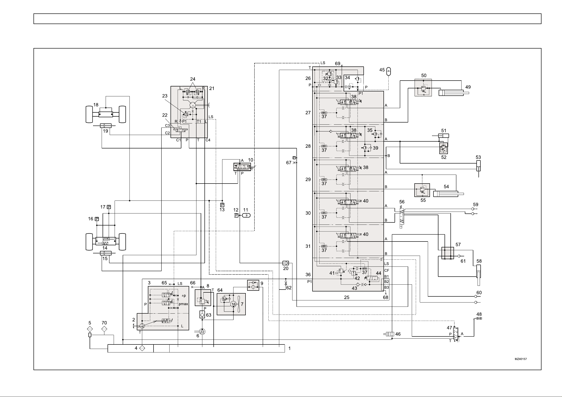
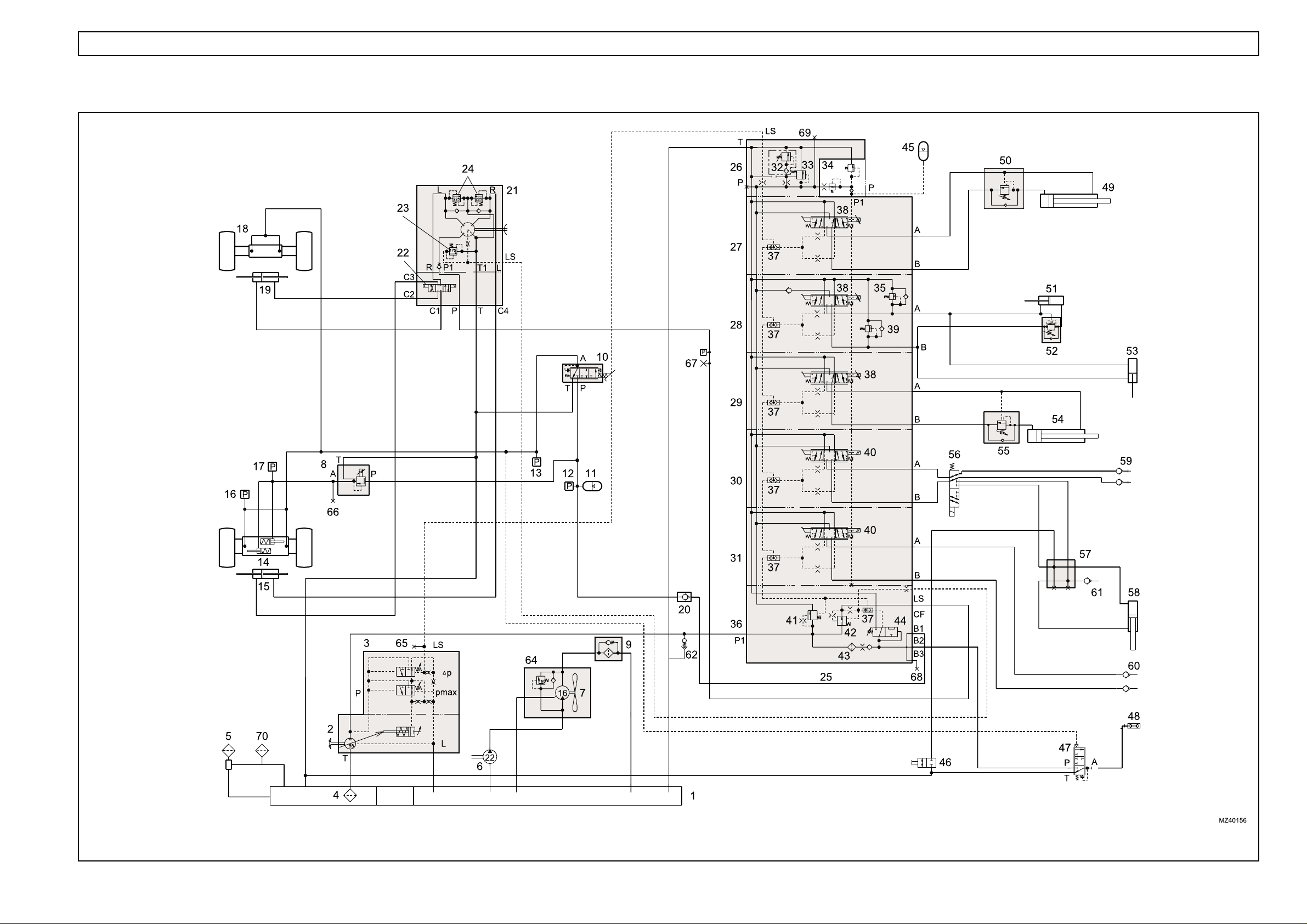
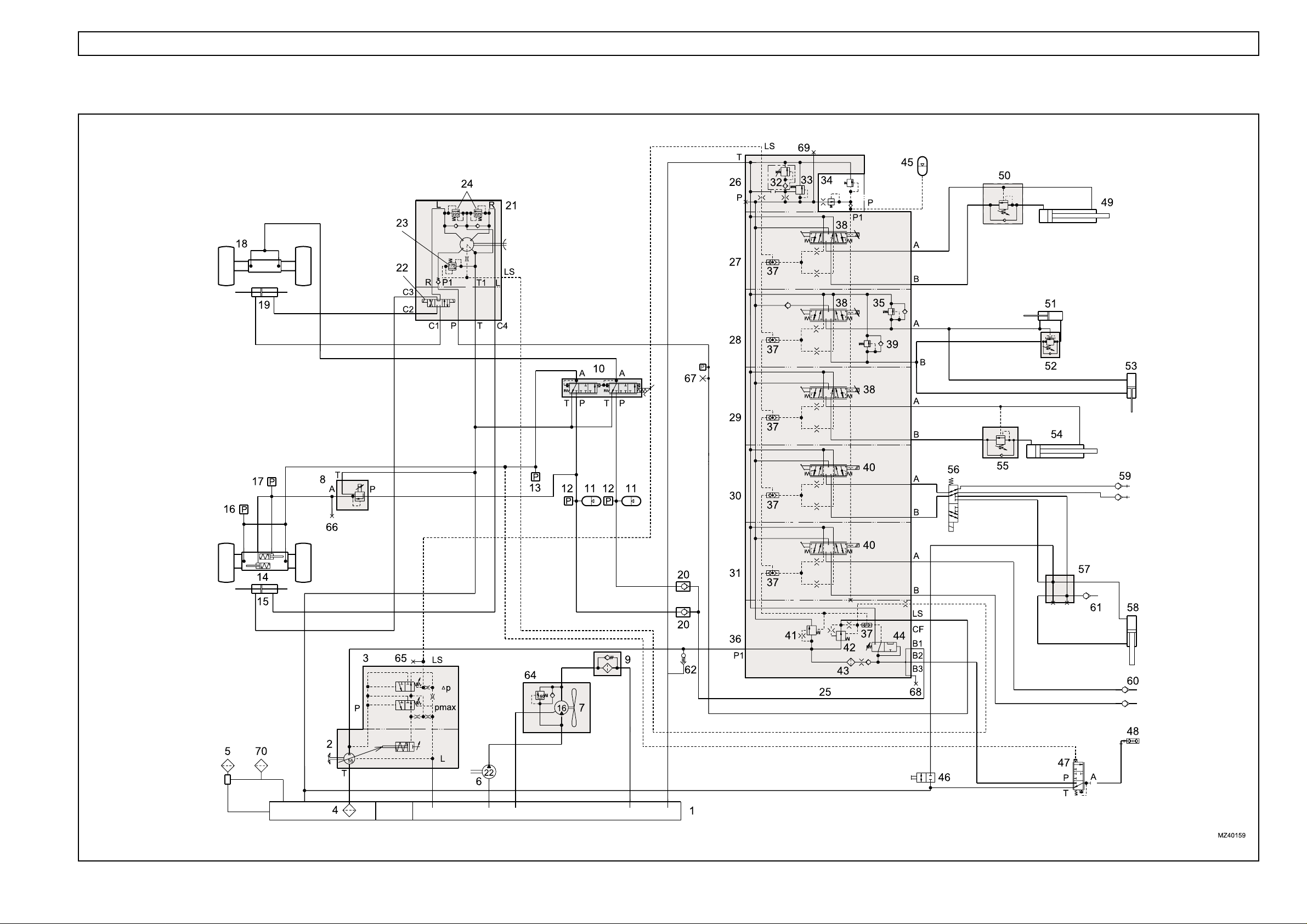
HYDRAULIC CIRCUIT - SINGLE CIRCUIT BRAKING (up to Machine S/No.51200317)

HYDRAULICS 1.3
Key to hydraulic circuit - single circuit braking
1. Hydraulic tank (reservoir)
2. Hydraulic pump, load sensing (LS)
3. LS pump compensator
4. Gauze filter (Not Serviceable)
5. Filler/breather
6. Auxiliary hydraulic pump
7. Fan motor
8. Pressure reducing valve (parking brake control)
9. Pressure filter
10. Brake servo valve
11. Accumulator
12. Pressure switch (116 bar)
13. Pressure switch (15 bar)
14. Front axle (park brake actuators)
15. Steering cylinder (front)
16. Pressure switch (5 bar)
17. Pressure switch (16 bar)
18. Rear axle
19. Steering cylinder (rear)
20. Non-return valve
21. Steering control valve (Danfoss OSPF)
22. Steering selector valve (attached to OSPF
valve)
23. Pressure relief valve (175 bar)
24. Shock valve (225 - 245 bar)
25. Hydraulics control valve (PVG 32)
26. Outlet section (PVP)
27. Extension section
28. Crowd/compensator section
29. Lift section
30. 1st auxiliary section (carriage/autohitch)
31. 2nd auxiliary section
32. Pressure relief valve (290 bar)
33. Pressure raising spool
34. Pilot valve
35. Shock valve (175 bar)
36. Inlet section (PVSP)
37. LS shuttle valve
38. Proportional controller
39. Shock valve (265 bar)
40. Controller (not proportional)
41. Priority valve (brakes and steering)
42. Priority valve (steering)
43. Filter
44. Brake accumulator charge valve (BAC)
45. Accumulator
(up to Machine S/No.51200317)
46. Tap
47. Trailer brake valve
48. Trailer brake coupling
49. Extension cylinder
50. Load control valve
51. Crowd cylinder
52. Load control valve
53. Compensator cylinder
54. Lift cylinder
55. Load control valve
56. Diverter valve
57. Manifold
58. Cylinder, autohitch
59. 1st service couplings
60. 2nd service couplings
61. Trailer tipping coupling
62. Start-up valve
63. Non-return valve
64. Pressure relief valve (160 bar)
65. Test point 1 (main system pressure LS)
66. Test point 2 (parking brake release pressure)
67. Test point 3 (steering system pressure)
68. Test point 4 (brake circuit)
69. Test point 5 (main circuit pressure P)
70. Auxiliary breather
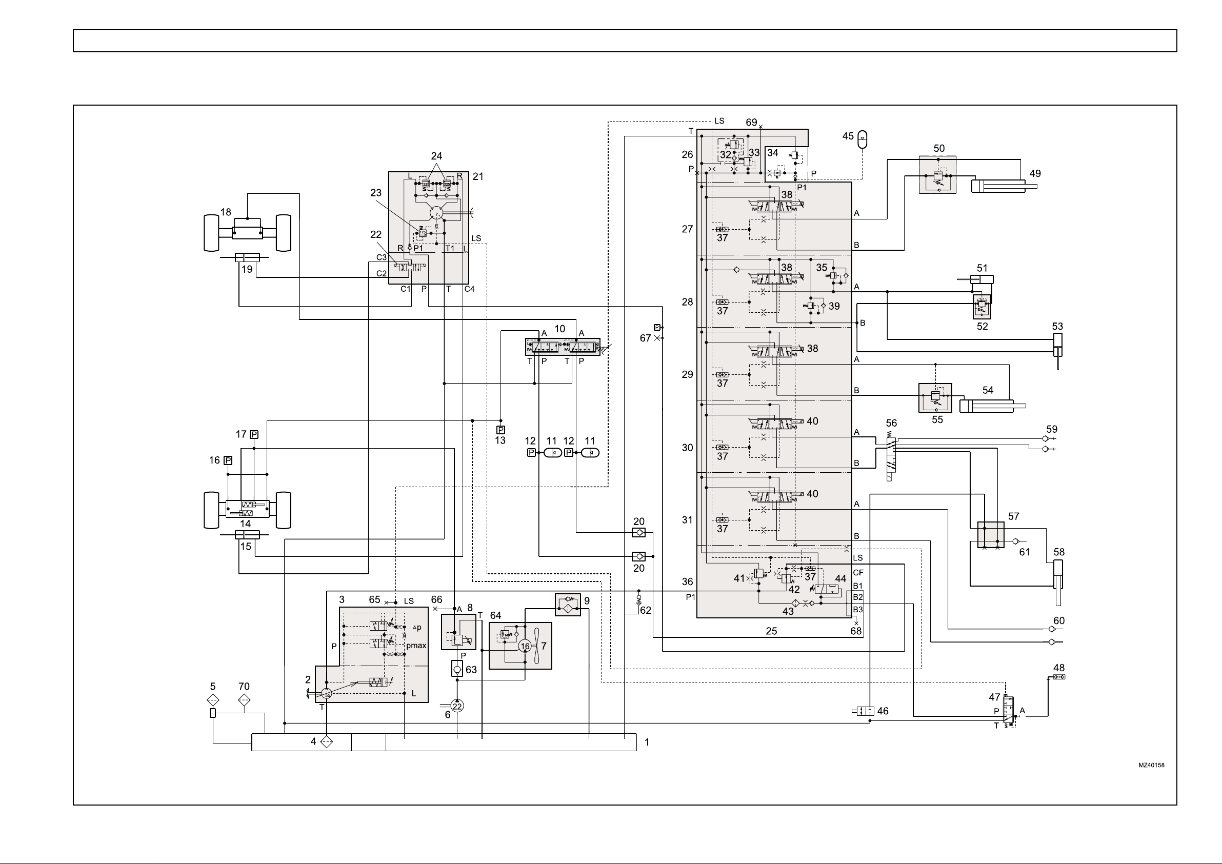
HYDRAULICS 1.4
HYDRAULIC CIRCUIT - SINGLE CIRCUIT BRAKING (from Machine S/No.51200318 to 51200471)

HYDRAULICS 1.5
Key to hydraulic circuit - single circuit braking
1. Hydraulic tank
2. Hydraulic pump, load sensing (LS)
3. LS pump compensator
4. Gauze filter (Not Serviceable)
5. Filler/breather
6. Auxiliary hydraulic pump
7. Fan motor
8. Pressure reducing valve (parking brake control)
9. Pressure filter
10. Brake valve
11. Accumulator
12. Pressure switch (116 bar)
13. Pressure switch (15 bar)
14. Front axle (park brake actuators)
15. Steering cylinder (front)
16. Pressure switch (5 bar)
17. Pressure switch (16 bar)
18. Rear axle
19. Steering cylinder (rear)
20. Non-return valve
21. Steering control valve (Danfoss OSPF)
22. Steering selector valve (attached to OSPF
valve)
23. Pressure relief valve (175 bar)
24. Shock valve (225 - 245 bar)
25. Hydraulic control valve (PVG 32)
26. Outlet section (PVP)
27. Extension section
28. Crowd/compensator section
29. Lift section
30. 1st auxiliary section (carriage/autohitch)
31. 2nd auxiliary section
32. Pressure relief valve (290 bar)
33. Pressure raising spool
34. Pilot valve
35. Shock valve (175 bar)
36. Inlet section (PVSP)
37. LS shuttle valve
38. Proportional controller
39. Shock valve (265 bar)
40. Controller (not proportional)
41. Priority valve (brakes and steering)
42. Priority valve (steering)
43. Filter
44. Brake accumulator charge valve (BAC)
45. Accumulator
(from Machine S/No.51200318 to 51200471)
46. Tap
47. Trailer brake valve
48. Trailer brake coupling
49. Extension cylinder
50. Load control valve
51. Crowd cylinder
52. Load control valve
53. Compensator cylinder
54. Lift cylinder
55. Load control valve
56. Diverter valve
57. Manifold
58. Cylinder (autohitch)
59. 1st service couplings
60. 2nd service couplings
61. Trailer tipping coupling
62. Start-up valve
63. NOT FITTED
64. Pressure relief valve (160 bar)
65. Test point 1 (main system pressure LS)
66. Test point 2 (parking brake release pressure)
67. Test point 3 (steering system pressure)
68. Test point 4 (brake circuit)
69. Test point 5 (main circuit pressure P)
70. Auxiliary breather
HYDRAULICS 1.6
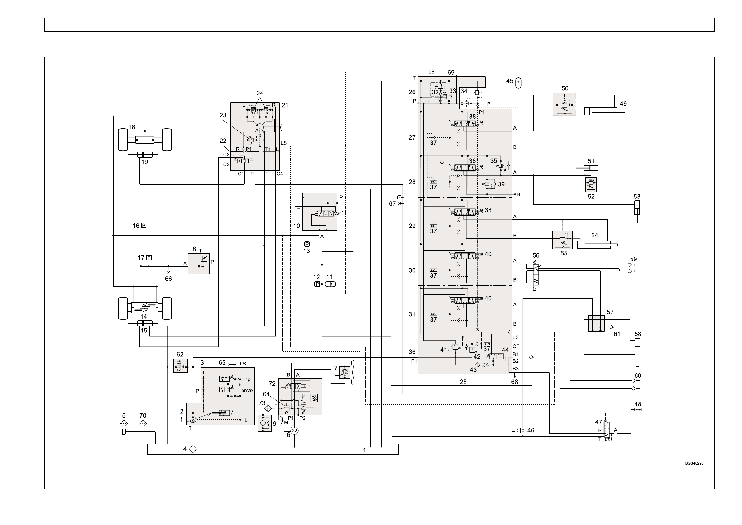
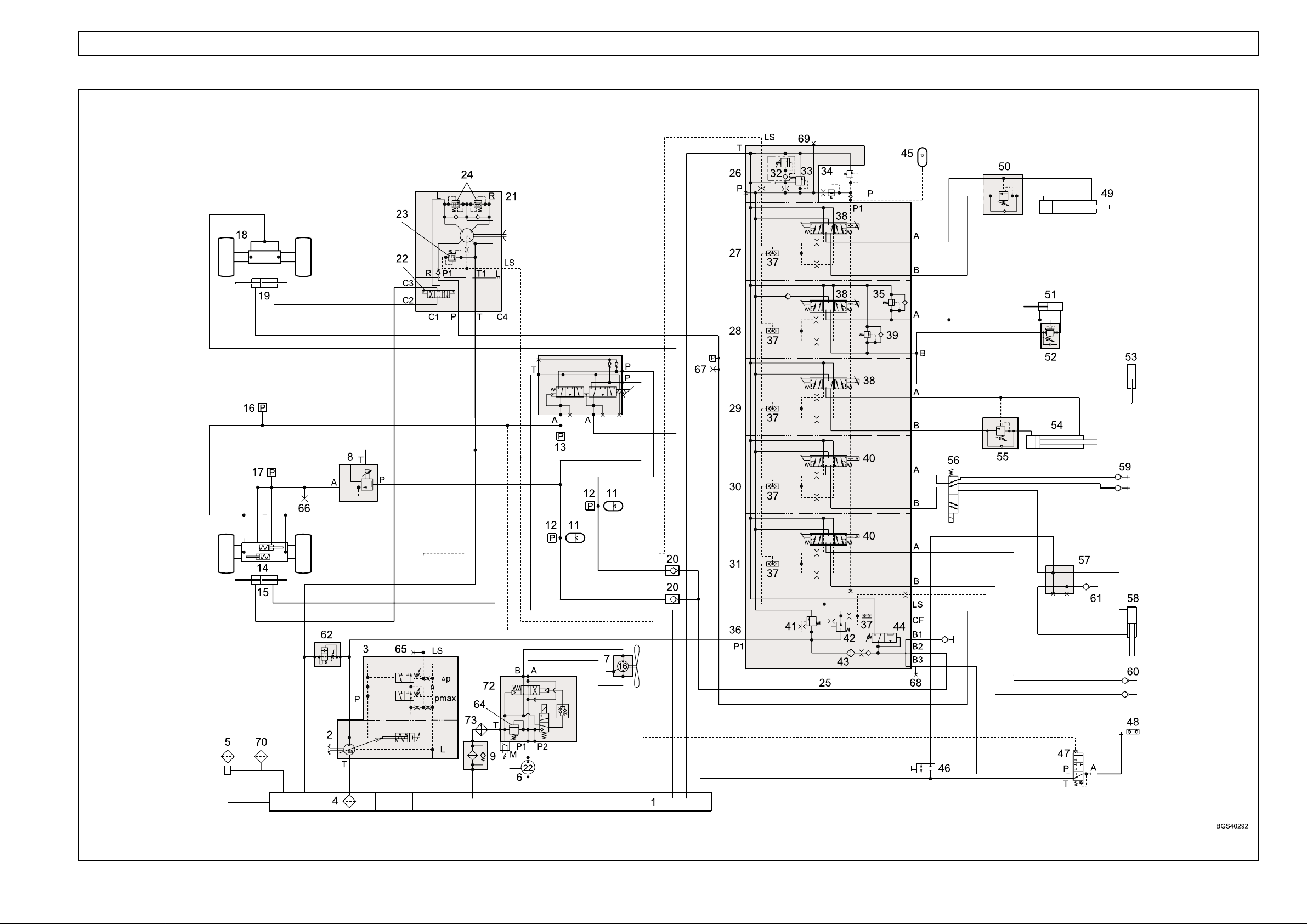
HYDRAULIC CIRCUIT - SINGLE CIRCUIT BRAKING (from Machine S/No. 51200472 to 51200551)

HYDRAULICS 1.7
Key to hydraulic circuit - single circuit braking
1. Hydraulic tank
2. Hydraulic pump, load sensing (LS)
3. LS pump compensator
4. Gauze filter (Not Serviceable)
5. Filler/breather
6. Auxiliary hydraulic pump
7. Fan motor
8. Pressure reducing valve (parking brake control)
9. Pressure filter
10. Brake valve (Safim type)
11. Accumulator
12. Pressure switch (116 bar)
13. Pressure switch (15 bar)
14. Front axle (park brake actuators)
15. Steering cylinder (front)
16. Pressure switch (5 bar)
17. Pressure switch (16 bar)
18. Rear axle
19. Steering cylinder (rear)
20. NOT FITTED
21. Steering control valve (Danfoss OSPF)
22. Steering selector valve (attached to OSPF
valve)
23. Pressure relief valve (175 bar)
24. Shock valve (225 - 245 bar)
25. Hydraulic control valve (PVG 32)
26. Outlet section (PVP)
27. Extension section
28. Crowd/compensator section
29. Lift section
30. 1st auxiliary section (carriage/autohitch)
31. 2nd auxiliary section
32. Pressure relief valve (290 bar)
33. Pressure raising spool
34. Pilot valve
35. Shock valve (175 bar)
36. Inlet section (PVSP)
37. LS shuttle valve
38. Proportional controller
39. Shock valve (265 bar)
40. Controller (not proportional)
41. Priority valve (brakes and steering)
42. Priority valve (steering)
43. Filter
44. Brake accumulator charge valve (BAC)
45. Accumulator
(from Machine S/No.51200472 to 51200551)
46. Tap
47. Trailer brake valve
48. Trailer brake coupling
49. Extension cylinder
50. Load control valve
51. Crowd cylinder
52. Load control valve
53. Compensator cylinder
54. Lift cylinder
55. Load control valve
56. Diverter valve
57. Manifold
58. Cylinder, autohitch
59. 1st service couplings
60. 2nd service couplings
61. Trailer tipping coupling
62. Start-up valve
63. NOT FITTED
64. Pressure regulator, 120 bar
65. Test point 1 (main system pressure LS)
66. Test point 2 (parking brake release pressure)
67. Test point 3 (steering system pressure)
68. Test point 4 (brake circuit)
69. Test point 5 (main circuit pressure P)
70. Auxiliary breather
71. NOT FITTED
72. Fan reverse valve
73. Oil cooler
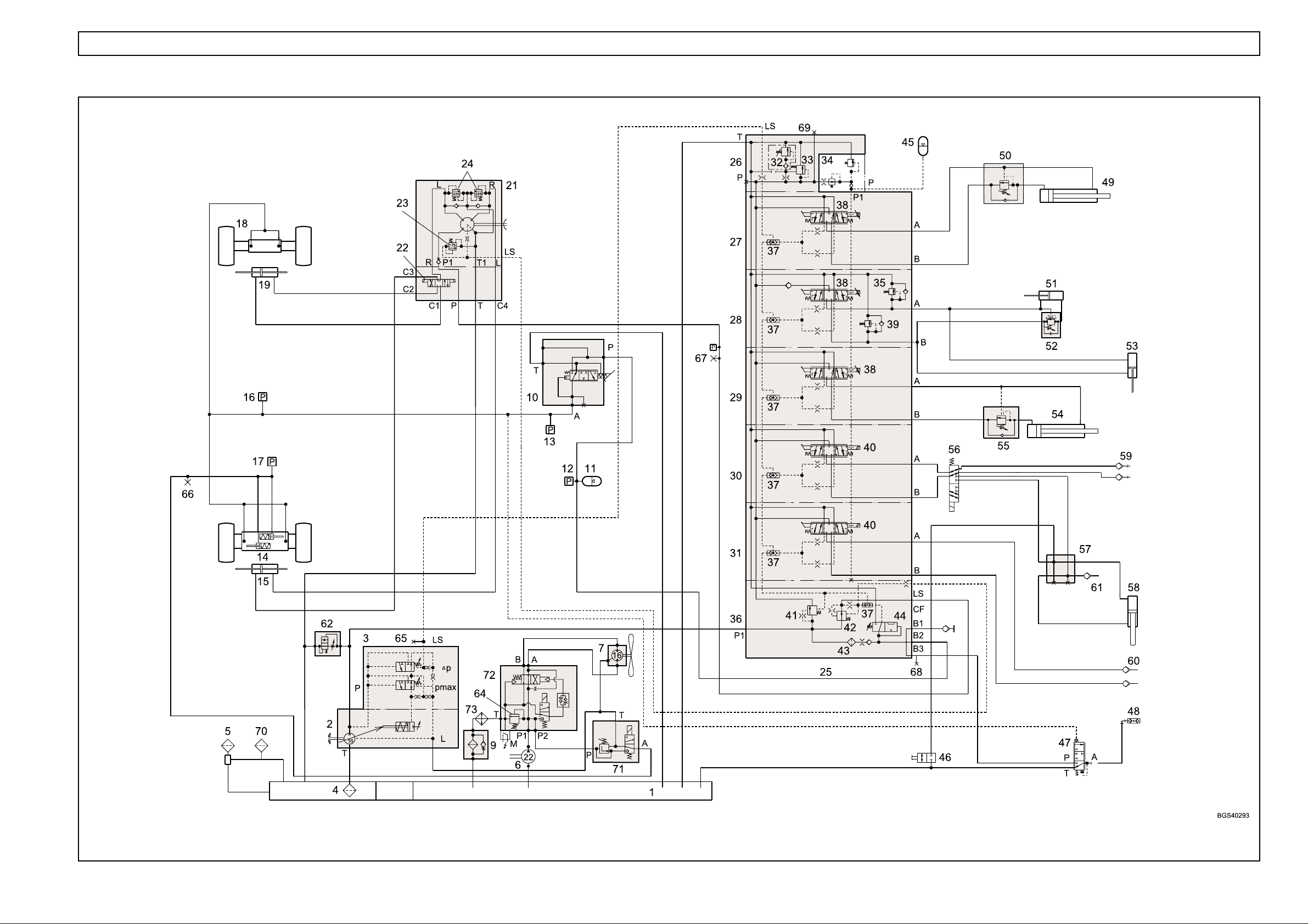
HYDRAULICS 1.8
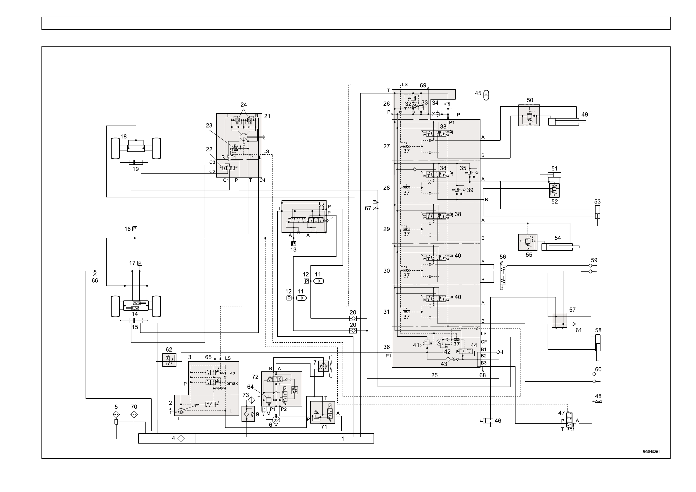
HYDRAULIC CIRCUIT - SINGLE CIRCUIT BRAKING (from Machine S/No. 51200552 to 51200727)

HYDRAULICS 1.9
Key to hydraulic circuit - single circuit braking
1. Hydraulic tank
2. Hydraulic pump, load sensing (LS)
3. LS pump compensator
4. Gauze filter (Not Serviceable)
5. Filler/breather
6. Auxiliary hydraulic pump
7. Fan motor
8. NOT FITTED
9. Pressure filter
10. Brake valve (Safim type)
11. Accumulator
12. Pressure switch (116 bar)
13. Pressure switch (15 bar)
14. Front axle (park brake actuators)
15. Steering cylinder (front)
16. Pressure switch (5 bar)
17. Pressure switch (16 bar)
18. Rear axle
19. Steering cylinder (rear)
20. NOT FITTED
21. Steering control valve (Danfoss OSPF)
22. Steering selector valve (attached to OSPF
valve)
23. Pressure relief valve (175 bar)
24. Shock valve (225 - 245 bar)
25. Hydraulic control valve (PVG 32)
26. Outlet section (PVP)
27. Extension section
28. Crowd/compensator section
29. Lift section
30. 1st auxiliary section (carriage/autohitch)
31. 2nd auxiliary section
32. Pressure relief valve (290 bar)
33. Pressure raising spool
34. Pilot valve
35. Shock valve (175 bar)
36. Inlet section (PVSP)
37. LS shuttle valve
38. Proportional controller
39. Shock valve (265 bar)
40. Controller (not proportional)
41. Priority valve (brakes and steering)
42. Priority valve (steering)
43. Filter
44. Brake accumulator charge valve (BAC)
45. Accumulator
(from Machine S/No.51200552 to 51200727)
46. Tap
47. Trailer brake valve
48. Trailer brake coupling
49. Extension cylinder
50. Load control valve
51. Crowd cylinder
52. Load control valve
53. Compensator cylinder
54. Lift cylinder
55. Load control valve
56. Diverter valve
57. Manifold
58. Cylinder, autohitch
59. 1st service couplings
60. 2nd service couplings
61. Trailer tipping coupling
62. Start-up valve
63. NOT FITTED
64. Pressure regulator, 120 bar
65. Test point 1 (main system pressure LS)
66. Test point 2 (parking brake release pressure)
67. Test point 3 (steering system pressure)
68. Test point 4 (brake circuit)
69. Test point 5 (main circuit pressure P)
70. Auxiliary breather
71. Parking brake valve
72. Fan reverse valve
73. Oil cooler
HYDRAULICS 1.10
HYDRAULIC CIRCUIT - DUAL CIRCUIT BRAKING (up to Machine S/No.51200317)

HYDRAULICS 1.11
Key to hydraulic circuit - dual circuit braking
1. Hydraulic tank
2. Hydraulic pump, load sensing (LS)
3. LS pump compensator
4. Gauze filter (Not Serviceable)
5. Filler/breather
6. Auxiliary hydraulic pump
7. Fan motor
8. Pressure reducing valve (parking brake control)
9. Pressure filter
10. Brake valve
11. Accumulator
12. Pressure switch (116 bar)
13. Pressure switch (15 bar)
14. Front axle (park brake actuators)
15. Steering cylinder (front)
16. Pressure switch (5 bar)
17. Pressure switch (16 bar)
18. Rear axle
19. Steering cylinder (rear)
20. Non-return valve
21. Steering control valve (Danfoss OSPF)
22. Steering selector valve (attached to OSPF
valve)
23. Pressure relief valve (175 bar)
24. Shock valve (225 - 245 bar)
25. Hydraulic control valve (PVG 32)
26. Outlet section (PVP)
27. Extension section
28. Crowd/compensator section
29. Lift section
30. 1st auxiliary section (carriage/autohitch)
31. 2nd auxiliary section
32. Pressure relief valve (290 bar)
33. Pressure raising spool
34. Pilot valve
35. Shock valve (175 bar)
36. Inlet section (PVSP)
37. LS shuttle valve
38. Proportional controller
39. Shock valve (265 bar)
40. Controller, (not proportional)
41. Priority valve (brakes and steering)
42. Priority valve (steering)
43. Filter
44. Brake accumulator charge valve (BAC)
45. Accumulator
(up to Machine S/No.51200317)
46. Tap
47. Trailer brake valve
48. Trailer brake coupling
49. Extension cylinder
50. Load control valve
51. Crowd cylinder
52. Load control valve
53. Compensator cylinder
54. Lift cylinder
55. Load control valve
56. Diverter valve
57. Manifold
58. Cylinder, autohitch
59. 1st service couplings
60. 2nd service couplings
61. Trailer tipping coupling
62. Start-up valve
63. Non-return valve
64. Pressure relief valve (160 bar)
65. Test point 1 (main system pressure LS)
66. Test point 2 (parking brake release pressure)
67. Test point 3 (steering system pressure)
68. Test point 4 (brake circuit)
69. Test point 5 (main circuit pressure P)
70. Auxiliary breather
HYDRAULICS 1.12
HYDRAULIC CIRCUIT - DUAL CIRCUIT BRAKING (from Machine S/No.51200318 to 51200471)

HYDRAULICS 1.13
Key to hydraulic circuit - dual circuit braking
1. Hydraulic tank
2. Hydraulic pump, load sensing (LS)
3. LS pump compensator
4. Gauze filter (Not Serviceable)
5. Filler/breather
6. Auxiliary hydraulic pump
7. Fan motor
8. Pressure reducing valve (parking brake
control)
9. Pressure filter
10. Brake valve
11. Accumulator
12. Pressure switch (116 bar)
13. Pressure switch (15 bar)
14. Front axle (park brake actuators)
15. Steering cylinder (front)
16. Pressure switch (5 bar)
17. Pressure switch (16 bar)
18. Rear axle
19. Steering cylinder (rear)
20. Non-return valve
21. Steering control valve (Danfoss OSPF)
22. Steering selector valve (attached to OSPF valve)
23. Pressure relief valve (175 bar)
24. Shock valve (225 - 245 bar)
25. Hydraulic control valve (PVG 32)
26. Outlet section (PVP)
27. Extension section
28. Crowd/compensator section
29. Lift section
30. 1st auxiliary section (carriage/autohitch)
31. 2nd auxiliary section
32. Pressure relief valve, 290 bar
33. Pressure raising spool
34. Pilot valve
35. Shock valve (175 bar)
36. Inlet section (PVSP)
37. LS shuttle valve
38. Proportional controller
39. Shock valve (265 bar)
40. Controller (not proportional)
41. Priority valve (brakes and steering)
42. Priority valve, steering
43. Filter
44. Brake accumulator charge valve (BAC)
45. Accumulator
(from Machine S/No.51200318 TO 512471)
46. Tap
47. Trailer brake valve
48. Trailer brake coupling
49. Extension cylinder
50. Load control valve
51. Crowd cylinder
52. Load control valve
53. Compensator cylinder
54. Lift cylinder
55. Load control valve
56. Diverter valve
57. Manifold
58. Cylinder, autohitch
59. 1st service couplings
60. 2nd service couplings
61. Trailer tipping coupling
62. Start-up valve
63. NOT FITTED
64. Pressure relief valve (160 bar)
65. Test point 1 (main system pressure LS)
66. Test point 2 (Park brake release pressure)
67. Test point 3 (steering system pressure)
68. Test point 4 (brake circuit)
69. Test point 5 (main circuit pressure P)
70 Auxiliary breather
HYDRAULICS 1.14
HYDRAULIC CIRCUIT - DUAL CIRCUIT BRAKING (from Machine S/No.51200472 to 51200551)

HYDRAULICS 1.15
Key to hydraulic circuit - dual circuit braking
1. Hydraulic tank
2. Hydraulic pump, load sensing (LS)
3. LS pump compensator
4. Gauze filter (Not Serviceable)
5. Filler/breather
6. Auxiliary hydraulic pump
7. Fan motor
8. Pressure reducing valve (parking brake
control)
9. Pressure filter
10. Brake valve
11. Accumulator
12. Pressure switch (116 bar)
13. Pressure switch (15 bar)
14. Front axle (park brake actuators)
15. Steering cylinder (front)
16. Pressure switch (5 bar)
17. Pressure switch (16 bar)
18. Rear axle
19. Steering cylinder (rear)
20. Non-return valve
21. Steering control valve (Danfoss OSPF)
22. Steering selector valve (attached to OSPF valve)
23. Pressure relief valve (175 bar)
24. Shock valve (225 - 245 bar)
25. Hydraulic control valve (PVG 32)
26. Outlet section (PVP)
27. Extension section
28. Crowd/compensator section
29. Lift section
30. 1st auxiliary section (carriage/autohitch)
31. 2nd auxiliary section
32. Pressure relief valve, 290 bar
33. Pressure raising spool
34. Pilot valve
35. Shock valve (175 bar)
36. Inlet section (PVSP)
37. LS shuttle valve
38. Proportional controller
39. Shock valve (265 bar)
40. Controller (not proportional)
41. Priority valve (brakes and steering)
42. Priority valve, steering
43. Filter
44. Brake accumulator charge valve (BAC)
45. Accumulator
(from Machine S/No.51200472 TO 512551)
46. Tap
47. Trailer brake valve
48. Trailer brake coupling
49. Extension cylinder
50. Load control valve
51. Crowd cylinder
52. Load control valve
53. Compensator cylinder
54. Lift cylinder
55. Load control valve
56. Diverter valve
57. Manifold
58. Cylinder, autohitch
59. 1st service couplings
60. 2nd service couplings
61. Trailer tipping coupling
62. Start-up valve
63. NOT FITTED
64. Pressure regulator, 120 bar
65. Test point 1 (main system pressure LS)
66. Test point 2 (Park brake release pressure)
67. Test point 3 (steering system pressure)
68. Test point 4 (brake circuit)
69. Test point 5 (main circuit pressure P)
70 Auxiliary breather
71. NOT FITTED
72. Fan reverse valve
73. Oil cooler
HYDRAULICS 1.16
HYDRAULIC CIRCUIT - DUAL CIRCUIT BRAKING (from Machine S/No.51200552 to 51200727)

HYDRAULICS 1.17
Key to hydraulic circuit - dual circuit braking
1. Hydraulic tank
2. Hydraulic pump, load sensing (LS)
3. LS pump compensator
4. Gauze filter (Not Serviceable)
5. Filler/breather
6. Auxiliary hydraulic pump
7. Fan motor
8. NOT FITTED
9. Pressure filter
10. Brake valve (Safim type)
11. Accumulator
12. Pressure switch (116 bar)
13. Pressure switch (15 bar)
14. Front axle (park brake actuators)
15. Steering cylinder (front)
16. Pressure switch (5 bar)
17. Pressure switch (16 bar)
18. Rear axle
19. Steering cylinder (rear)
20. Non-return valve
21. Steering control valve (Danfoss OSPF)
22. Steering selector valve (attached to OSPF valve)
23. Pressure relief valve (175 bar)
24. Shock valve (225 - 245 bar)
25. Hydraulic control valve (PVG 32)
26. Outlet section (PVP)
27. Extension section
28. Crowd/compensator section
29. Lift section
30. 1st auxiliary section (carriage/autohitch)
31. 2nd auxiliary section
32. Pressure relief valve, 290 bar
33. Pressure raising spool
34. Pilot valve
35. Shock valve (175 bar)
36. Inlet section (PVSP)
37. LS shuttle valve
38. Proportional controller
39. Shock valve (265 bar)
40. Controller (not proportional)
41. Priority valve (brakes and steering)
42. Priority valve, steering
43. Filter
44. Brake accumulator charge valve (BAC)
45. Accumulator
(from Machine S/No.51200552 TO 512727)
46. Tap
47. Trailer brake valve
48. Trailer brake coupling
49. Extension cylinder
50. Load control valve
51. Crowd cylinder
52. Load control valve
53. Compensator cylinder
54. Lift cylinder
55. Load control valve
56. Diverter valve
57. Manifold
58. Cylinder, autohitch
59. 1st service couplings
60. 2nd service couplings
61. Trailer tipping coupling
62. Start-up valve
63. NOT FITTED
64. Pressure regulator, 120 bar
65. Test point 1 (main system pressure LS)
66. Test point 2 (Park brake release pressure)
67. Test point 3 (steering system pressure)
68. Test point 4 (brake circuit)
69. Test point 5 (main circuit pressure P)
70 Auxiliary breather
71. Parking brake valve
72. Fan reverse valve
73. Oil cooler
1.18 HYDRAULICS
COMPONENTS
General
NOTE: An identification number in bold type, after an
item, refers to the number of that item in the main
hydraulic schematic illustration.
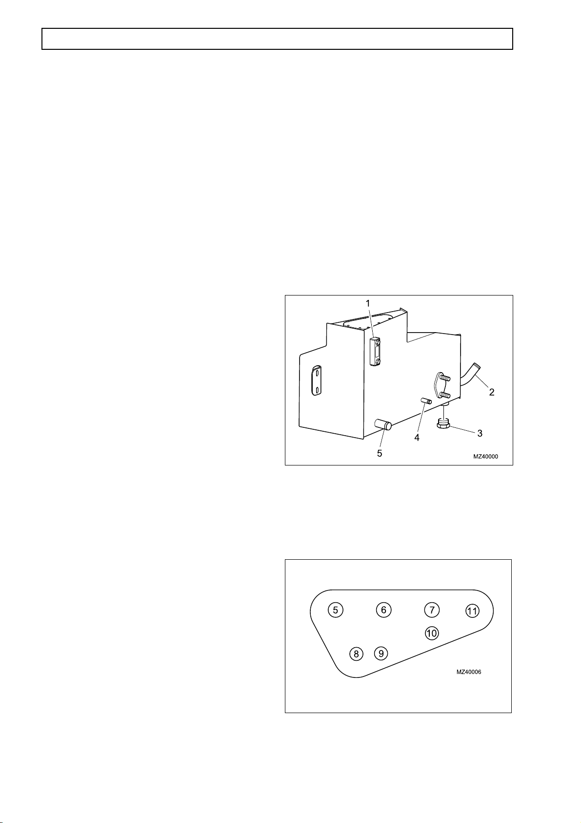
Hydraulic tank (1)
A single hydraulic reservoir feeds the main and
auxiliary systems of the machine. A sight glass is
fitted to check system contents. An internal 40 µm
mesh filter (pre-filtration) separates the clean and
dirty sides of the tank. Both system suction lines are
taken from the clean side of the mesh filter. All
return lines go to a manifold and return fluid to dirty
side of tank for pre filtration.
Specifications:
Nominal tank capacity 67 litres
Total system capacity (oil) 128 litres
Suction line connections to hydraulic tank
1. Sight glass
2. Suction - Main Pump
3. Drain plug
4. Suction - Auxiliary Pump
5. Filler
Return hose connections to hydraulic tank
(up to Machine S/No.51200471)
5. Return from PVG (Main Control Valve)
6. Return from LS Pump and Filter
7. From LS Pump Case Drain
8. Breather (connected to Filler)
9. Return from Brake and Steering circuits
10. From Trailer Brake (optional)
11. Return from Parking Brake PRV
Return hose connections to hydraulic tank
(from Machine S/No.51200472)
5. Return from PVG (Main Control Valve)
6. Return from LS Pump and Filter
7. (Blank fitted)
8. Breather (connected to Filler)
9. Return from Brake circuit
10. From Trailer Brake (optional)
11. Return from Brake and Parking Brake circuit
 Loading...