

Page 1

ROLLANT 240
ROLLANT 250 / 250 ROTO CUT
ROLLANT 254 ROTO CUT
ROLLANT 255 ROTO CUT
Operating
instructions
Page 2

e
s
ve
r
s
f
a
ty
e
eg
r
l
u
t
a
o
i
!
s
n
e
R
d
a
a
d
n
o
b
Page 3

1
Introduction
Page 4

Page 5

Introduction
Introduction
INTRODUCTION
This operating manual for the Rollant 240/250/254/255
round baler (applicable from 72505431/74800011/
75400011/74900011) is primarily intended for the
machine operator; it provides information on the use of
the round baler, including its settings and operation.
Please comply with the guidelines for correct care and
maintenance of your round baler to ensure permanent
availability and a long service life of the round baler.
Have your round baler inspected by your CLAAS
workshop immediately after harvest within the
framework of these winter storage recommendations.
Deficiencies in maintenance or incorrect operation
lead to a drop in performance and result in time losses.
Use the experience and latest knowledge in long stalk
harvest implemented in this round baler by correct
operation and thorough maintenance, and your round
baler will always produce excellent results.
Your CLAAS Service Department
000 299 119 5 - BA ROLLANT 240 - 250 - 254 - 255 1.1.1
Page 6

Introduction
1.1.2 BA ROLLANT 240 - 250 - 254 - 255 - 000 299 119 5
Page 7

2
Contents
Page 8

Page 9

Contents
CONTENTS
Contents
1. Introduction
Introduction ............................................................................ 1.1.1
2. Contents
3. General notes
Road traffic ............................................................................ 3.1.1
To be observed especially ..................................................... 3.2.1
Type plate (baler) ............................................................ 3.3.1
Machine serial number .................................................... 3.3.1
4. Safety precautions
Safety precautions ................................................................. 4.1.1
Personal injury may result if these safety precautions
are not followed ............................................................... 4.1.1
Safety signs ..................................................................... 4.1.3
Transporting baler on a public thoroughfare .................... 4.1.3
Transporting baler on a public thoroughfare .......................... 4.1.5
Recommended warning lights ......................................... 4.1.5
Preparing for transport ..................................................... 4.1.5
4.
4. Safety signs
5. Specifications
CLAAS Rollant 240/250/Rollant 250/254/255 RC .................. 5.1.1
Feeder mechanisms ........................................................ 5.1.1
Wrapping unit .................................................................. 5.1.2
Wheels ............................................................................. 5.1.3
Hydraulic system ............................................................. 5.1.3
Required tractor hydraulics .............................................. 5.1.3
Flow rate of hydraulic oil .................................................. 5.1.3
Electrical systems ............................................................ 5.1.3
Weights ............................................................................ 5.1.3
CLAAS Rollant 240/250/Rollant 250/254/255 RC .................. 5.1.4
Dimensions of the round baler ......................................... 5.1.4
CLAAS Rollant 240/250/Rollant 250/254/255 RC .................. 5.1.5
Safety features ....................................................................... 5.1.5
6. Description and function
Transmission of power .................................................... 6.1.1
Pick-up ............................................................................. 6.1.1
Crop guard ....................................................................... 6.1.1
Baffle plate ....................................................................... 6.1.1
Roller crop guard ............................................................. 6.1.1
Cutting unit
(ROLLANT 250/254/255 RC) .......................................... 6.1.1
Rotor backwinding unit
(ROLLANT 240/250/254/255) .......................................... 6.1.2
Hydraulic rotor reverse device
(ROLLANT 254/255 with control panel) ........................... 6.1.2
Hydraulic rotor reverse device from tractor
(ROLLANT 250/254/255) ................................................. 6.1.2
Bale chamber .................................................................. 6.1.2
Wrapping ......................................................................... 6.1.2
Bale discharge ramp ........................................................ 6.1.3
Bale transport .................................................................. 6.1.3
Storage of round bales .................................................... 6.1.3
7. Prior to operation
Check and observe before starting operation ....................... 7.1.1
Attach the baler ..................................................................... 7.2.1
Connecting the universal drive shaft to the baler ............ 7.2.1
Universal drive shaft with taper lock ................................ 7.2.2
Fitting the drive shaft with the CC taper lock ................... 7.2.2
Jack stand ....................................................................... 7.2.2
Before you hitch the baler: .............................................. 7.2.2
Attaching to the swinging drawbar with a safety nut ....... 7.2.3
Attaching to the swinging drawbar with a counter nut ..... 7.2.4
Adjusting the length of the drawbar fork arms ................. 7.2.4
Adjusting the hitch eye .................................................... 7.2.5
Greasing the hitch eye .................................................... 7.2.5
Connecting the universal drive shaft to the tractor
(for swinging drawbar hitching) ....................................... 7.2.6
Shortening the propeller shaft ......................................... 7.2.7
Attaching to the jaw-type hitch with a safety nut
(In Germany only permitted with
type-approved drawbar) .................................................. 7.2.8
Attaching to the jaw-type hitch with a counter nut ........... 7.2.9
Adjusting the drawbar fork arms ..................................... 7.2.9
Adjusting the hitch eye .................................................. 7.2.10
Set up ball head coupling .............................................. 7.2.10
Attaching the universal drive shaft to the tractor
(for top-fitted tow jaw) .................................................... 7.2.11
Electrical systems .................................................................. 7.3.1
Control box ...................................................................... 7.3.1
Standard operation .......................................................... 7.3.1
Control Terminal .............................................................. 7.3.1
Power supply ................................................................... 7.3.2
Machines with lighting equipment ................................... 7.3.2
Hydraulic System .................................................................. 7.4.1
Hydraulic system for standard machines ........................ 7.4.1
Hydraulic system of CLAAS Control Terminal models .... 7.4.2
Before transporting the baler ................................................. 7.5.1
Bale discharge ramp ............................................................. 7.6.1
Installing the bale discharge ............................................ 7.6.1
Ramp setting to signal bale ejection ............................... 7.6.5
8. Setting up the baler
Pick-up .................................................................................. 8.1.1
Pick-up, transport and work positions ............................. 8.1.1
Adjusting the working height of the pick-up
(pick-up without gauge wheels) ....................................... 8.1.1
Adjusting the working height of the pick-up
(pick-up with gauge wheels) ............................................ 8.1.1
Support wheels ............................................................... 8.1.2
Pick-up crop guard .......................................................... 8.1.2
Short crop baffle .............................................................. 8.1.2
Roller crop guard ............................................................. 8.1.3
Adjusting the roller crop guard ........................................ 8.1.4
Adjusting the roller crop guard where there are
problems with the bale material feed .............................. 8.1.5
Driving the baler with the roller crop guard ..................... 8.1.5
000 299 119 5 - BA ROLLANT 240 - 250 - 254 - 255 2.1.1
Page 10

Contents
Blockage in the roller crop guard ..................................... 8.1.6
Cutting unit
(ROLLANT 250/254/255 RC) ........................................... 8.1.7
Blanking knives ................................................................ 8.1.7
Installing and removing the knives ................................... 8.1.8
Locking the knives ........................................................... 8.1.8
Knife - blanking knife holder (option) ............................... 8.1.8
Hydraulic baling pressure preadjustment ........................ 8.1.9
Adjusting the baling pressure with a pivoting segment .. 8.1.10
Spring tension adjustment ............................................. 8.1.10
Safety lock for the tailgate ............................................. 8.1.11
Ladder
(for baling with net wrapping) ......................................... 8.1.11
Wrapping ................................................................................ 8.2.1
Net wrapping .................................................................... 8.2.1
Inserting the net ............................................................... 8.2.1
ROLLANT 240/250 with twine and net wrapping
(Standard) ........................................................................ 8.2.6
ROLLANT 254/255 with twine and net wrapping
(Standard) ........................................................................ 8.2.7
ROLLANT 254/255 with twine and net wrapping
(High Convenience) ......................................................... 8.2.7
Engaging the drive for net wrapping................................. 8.2.8
Disengaging the twine wrapping drive.............................. 8.2.8
V-belt drive for net wrapping ............................................ 8.2.8
Setting the number of net wraps ...................................... 8.2.9
Double twine wrapping .................................................. 8.2.10
Twine box ...................................................................... 8.2.10
Threading the twine ....................................................... 8.2.10
Threading the twine ROLLANT 240/250/254/255
with standard controls .................................................... 8.2.11
Threading the twine ROLLANT 254/255 with
CLAAS Control Terminal ............................................... 8.2.12
Adjusting the twine wrap on the outer edges
of the bale ...................................................................... 8.2.13
Turn in the twine deflector ............................................. 8.2.13
Engaging the drive for the twine wrapping
mechanism .................................................................... 8.2.13
Disengaging the drive of the net wrapping
mechanism .................................................................... 8.2.14
Setting the number of twine wraps ................................. 8.2.14
Discharging bales without the bale discharge unit.......... 8.2.15
Reel ........................................................................................ 8.3.1
9. Operation
Balers with standard Controls (ROLLANT 240/250) .............. 9.1.1
Automatic twine and net wrapping ................................... 9.1.2
Manual net wrapping ....................................................... 9.1.3
Wrapping ends ................................................................. 9.1.3
Discharging bales ............................................................ 9.1.4
Bale counter ..................................................................... 9.1.5
Switch position with net wrapping .................................... 9.1.5
Switch position with double twine wrapping ..................... 9.1.5
Manual override of automatic wrapping operation ........... 9.1.6
Delay time for automatic net wrapping ............................ 9.1.7
Checking the delay time .................................................. 9.1.7
Setting the delay time ...................................................... 9.1.8
Activate manual net wrapping .......................................... 9.1.9
Blockages .............................................................................. 9.2.1
Cam-type cut-out clutch – universal drive shaft
(optional equipment) ........................................................ 9.2.1
Rotor reverse, manual ..................................................... 9.2.2
Rotor reverse rotation device, hydraulic (from tractor)
(optional fitting for ROLLANT 250/254/255 with rotor
and standard operation) .................................................. 9.2.3
Cutting unit ...................................................................... 9.2.4
Engaging the knives ........................................................ 9.2.4
Disengaging the knives ................................................... 9.2.4
Switch position ................................................................ 9.2.4
Standard operation baling (ROLLANT 254/255) ............. 9.2.5
Starting operation of the round baler ............................... 9.2.6
Automatic wrapping ......................................................... 9.2.7
Binding and ejecting bales .............................................. 9.2.7
Laying down the bales ..................................................... 9.2.8
Bale counter .................................................................... 9.2.8
Round baler with net wrapping ........................................ 9.2.9
Round baler with twine and net wrapping ....................... 9.2.9
Round baler with twine wrapping .................................... 9.2.9
Manual overload of the automatic wrapping .................. 9.2.10
Triggering early wrapping .............................................. 9.2.10
Delaying the wrapping process: .................................... 9.2.10
Setting the delay period to automatic net binding ......... 9.2.11
Cutting device (ROTO CUT) ......................................... 9.2.11
Swashing the knives in .................................................. 9.2.11
Swashing the knives out ................................................ 9.2.12
Adjusting the volume of the audible warning signal ...... 9.2.12
10. Control Terminal
Baling with the high convenience operation
(optional for ROLLANT 254/255) ......................................... 10.1.1
Control terminal - overview ............................................ 10.1.2
Status display ................................................................ 10.1.3
Setting the type of wrapping .......................................... 10.1.4
Start wrapping cycle manually ....................................... 10.1.4
Delay wrapping cycle .................................................... 10.1.4
Pick-up up / down (without floating position) ................. 10.1.4
Pick-up in float position / up .......................................... 10.1.5
Engage / disengage knives ........................................... 10.1.5
Rotor reverse ................................................................. 10.1.5
Open / close tailgate ...................................................... 10.1.6
Job data ............................................................................... 10.2.1
Settings ................................................................................ 10.3.1
Set number of wraps ..................................................... 10.3.1
Call up “User settings” submenu ................................... 10.3.2
Making user settings ..................................................... 10.3.2
Setting the delay time until the start of automatic
or manual wrapping ....................................................... 10.3.3
Engaging / disengaging automatic tailgate
operation ....................................................................... 10.3.4
Manual override of automatic tailgate operation ........... 10.3.4
Recharge pressure ........................................................ 10.3.5
Clean knives .................................................................. 10.3.5
Select language ............................................................. 10.3.6
Bale wrapper ................................................................. 10.3.6
Counter ................................................................................ 10.4.1
Daily and overall counter ............................................... 10.4.1
Reset maintenance display ........................................... 10.4.2
2.1.2 BA ROLLANT 240 - 250 - 254 - 255 - 000 299 119 5
Page 11

Contents
Reset daily counter ........................................................ 10.4.2
Special counter .............................................................. 10.4.3
Start special counter ...................................................... 10.4.3
Correct bale count ......................................................... 10.4.4
Reset job ....................................................................... 10.4.4
Fault display ......................................................................... 10.5.1
Error display in text mode .............................................. 10.5.1
Switch off warning signal ............................................... 10.5.2
Delete fault .................................................................... 10.5.2
Application example ............................................................. 10.6.1
11. CLAAS COMMUNICATOR
Overview – CLAAS COMMUNICATOR
(ROLLANT 254/255 optional) .............................................. 11.1.1
Switching on the Claas Communicator .......................... 11.1.2
Overview – Claas Communicator .................................. 11.1.3
Incremental encoder and keys ...................................... 11.1.4
Incremental encoder ...................................................... 11.1.4
Softkeys ......................................................................... 11.1.4
Navigational keys for the menu ..................................... 11.1.4
Main menu ..................................................................... 11.1.5
Application menu ........................................................... 11.1.6
Work functions ............................................................... 11.1.6
Information window in the application menu .................. 11.1.7
Setup menu ................................................................... 11.1.7
Functions in the settings menu ...................................... 11.1.7
Functions with set parameters ....................................... 11.1.7
Counter menu ................................................................ 11.1.8
Main menu ..................................................................... 11.1.8
Display window current job ............................................ 11.1.8
Fault menu ..................................................................... 11.1.9
System information menu .............................................. 11.1.9
Operator settings ................................................................. 11.2.1
Select type of wrapping ................................................. 11.2.1
Setting the number of net windings ............................... 11.2.2
Setting the twine length ................................................. 11.2.2
Setting the delay between end of baling and start
of net wrapping .............................................................. 11.2.3
Setting the automatic opening of the tailgate ................ 11.2.4
Setting the recharging of the baling pressure in
the hydraulic cylinder ..................................................... 11.2.5
Knife cleaning sequence ............................................... 11.2.6
Settings in the counter menu ............................................... 11.3.1
Selecting job orders ....................................................... 11.3.1
Resetting the work record counter ................................. 11.3.1
Resetting the daily counter ............................................ 11.3.2
Resetting the service display ......................................... 11.3.2
Fault display ......................................................................... 11.4.1
Main menu »Service« .......................................................... 11.5.1
Opening the adjustment menu ...................................... 11.5.1
System information menu .............................................. 11.5.2
Image adjustment menu ................................................ 11.5.3
Setting the contrast ........................................................ 11.5.3
Setting the brightness .................................................... 11.5.3
Time and date menu ...................................................... 11.5.4
Setting the time or date ................................................. 11.5.4
Memory management menu .......................................... 11.5.5
Administration of the saved projects .............................. 11.5.5
Reduce conflicts between the baler and the tractor ...... 11.5.6
Language selection menu ............................................. 11.5.7
Setting the language ..................................................... 11.5.7
Aux. menu ..................................................................... 11.5.8
Pre-settings ......................................................................... 11.6.1
Pick-up function ................................................................... 11.6.1
Pick-up .......................................................................... 11.6.1
Activate cutting unit ....................................................... 11.6.2
Checking the position of the cutting unit ....................... 11.6.3
Standard machines: ...................................................... 11.6.3
Cutting unit active .......................................................... 11.6.3
Cutting unit deactivated ................................................. 11.6.3
Recharging the cylinder pressure starting with
the first bale ................................................................... 11.6.4
Process for activating the function starting with
the first bale ................................................................... 11.6.4
Turn rotor back .............................................................. 11.6.5
Baling and wrapping ...................................................... 11.6.6
Automatic twine wrapping ............................................. 11.6.6
Automatic net wrapping ................................................. 11.6.7
Manual wrapping - twine wrapping and net wrapping ... 11.6.8
Bale output .................................................................... 11.6.9
Automatic opening of tailgate ........................................ 11.6.9
Opening the tailgate manually ....................................... 11.6.9
Fault in the bale chute ................................................. 11.6.10
States of the baler ....................................................... 11.6.11
Twine wrapping without recharging the pressure ........ 11.6.11
Net wrapping without recharging the pressure ............ 11.6.13
12. Faults and remedies
Faults, Cause or remedy ..................................................... 12.1.1
Twine wrapping ............................................................. 12.1.1
Net wrapping ................................................................. 12.1.2
13. After using the baler
Unhitching the baler ............................................................ 13.1.1
Wheel chocks ................................................................ 13.1.1
Parking support ............................................................. 13.1.1
Control box .................................................................... 13.1.2
Standard operation ........................................................ 13.1.2
Control panel (ROLLANT 254/255 optional) ................. 13.1.2
Claas Communicator (ROLLANT 254/255 optional) ..... 13.1.3
Removing the hydraulic hoses and cables .................... 13.1.3
Propeller ........................................................................ 13.1.3
Castor gauge wheels (ROLLANT 250/245/255) ........... 13.1.4
14. Maintenance
Important notes on maintenance ......................................... 14.1.1
General notes on maintenance ..................................... 14.1.1
Maintenance and lubricant tables ........................................ 14.2.1
Maintenance table ......................................................... 14.2.1
Lubricants table ............................................................. 14.2.2
Drive system ........................................................................ 14.3.1
Shearing bolt on main drive
(optional for ROLLANT 240/250/254) ........................... 14.3.1
Shear bolt pick-up drive ................................................ 14.3.1
Angle drive gearbox ...................................................... 14.3.2
Adjusting the tension of the drive chains ....................... 14.3.3
Tightening the pick-up drive chain ................................ 14.3.4
Adjusting the chain tightener ......................................... 14.3.4
000 299 119 5 - BA ROLLANT 240 - 250 - 254 - 255 2.1.3
Page 12

Contents
Spring-loaded cylinder for bale-forming roller
drive – tailgate ............................................................... 14.3.5
Spring-loaded cylinder for the bottom bale-forming
roller drive ...................................................................... 14.3.5
Adjusting the spring-loaded cylinder for the front
bale-forming roller drive ................................................. 14.3.5
Adjustment of tension springs ........................................ 14.3.6
Adjusting the tension spring for the net roll tightening
clamp (Adjustment done without net roll) ....................... 14.3.6
Tension spring
(Adjustment done without net roll) ................................. 14.3.6
Adjusting the tension spring for the net brake ............... 14.3.7
Adjusting the pressure springs for the pressure roller ... 14.3.7
Adjusting the tightening device for the net knife ............ 14.3.7
Adjusting the twine tightener .......................................... 14.3.8
Adjusting the twine knife control .................................... 14.3.8
Lubrication system ............................................................... 14.4.1
Automatic chain lubrication ............................................ 14.4.1
Mechanical lubrication of the central chain
(Rollant 254/255 - Option) ............................................. 14.4.2
Overview of the mechanical lubricating pump ............... 14.4.2
Making adjustments to the mechanical
lubricating pump ............................................................ 14.4.2
....................................................................................... 14.4.2
Lubricant ........................................................................ 14.4.3
Bearings to be greased and main lubrication
installation (for ROLLANT 254/255 - optional) ............... 14.4.3
Automatic central lubrication of the bearing
(Rollant 254/255 - Option) ............................................. 14.4.4
Overview ........................................................................ 14.4.4
Adjusting the flow rate ................................................... 14.4.4
Setting the stop on the grease pump ............................. 14.4.5
Filling the grease container ............................................ 14.4.5
Cutting unit ........................................................................... 14.5.1
Adjusting the height of the cutting knives
(ROLLANT 250/254/255 RC) ......................................... 14.5.1
ROLLANT 254/255 - from 75400181/74802194 ............ 14.5.1
Hydraulic oil filter
(machine with filter system) ................................................. 14.6.1
Bleed valve combination with pressure limiting valve .... 14.6.2
Equipment ............................................................................ 14.7.1
Fire extinguisher (Rollant 254/255 optional) .................. 14.7.1
Clean the rollers (Rollant 254/255) ................................ 14.7.1
Tyres .................................................................................... 14.8.1
Check tight fit of wheel nuts ........................................... 14.8.1
Monitoring intervals ........................................................ 14.8.1
Procedure: ..................................................................... 14.8.1
Setting (locking) the bearing clearance ......................... 14.8.1
Proposals for winter storage ................................................ 14.9.1
15. Lubrication plan
Lubricants and notes ............................................................ 15.1.1
16. Index
2.1.4 BA ROLLANT 240 - 250 - 254 - 255 - 000 299 119 5
Page 13

3
General notes
Page 14

Page 15

General notes
General notes
ROAD TRAFFIC
The machine operator must always have a copy of
the General Type Approval (ABE) issued by the
Kraftfahrt Bundesamt (KBA) or the individual type
approval and two wheel chocks at hand.
When driving on public roads with the lof working
equipment attached, all duties determined under C
in the copy of the ABE issued by the KBA (§ 18,
para. 5 StVZO) or the duties and notes listed in the
individual type approval must be observed.
Above all, no bale must be in the round baler.
If parts of the baler, the conditions of which are
clearly specified, are later changed or modified in
such a way that their operation will endanger any
other participants in traffic, the type approval will
become invalid and a new type approval must be
applied for. In this case the Iof working equipment
must be presented to the responsible technical
inspection authority for motor vehicles (e.g. TÜV) for
issuing an expertise (§ 19 para. 2 StVZO).
If you are in doubt that this may be the case, please
contact us as the manufacturer.
If the round baler is pulled after a tractor, especially
the following devices have to be connected:
- The cable of the lighting equipment.
- The cable for power supply.
Before starting to drive the condition of:
- the connection between pulling vehicle and baler
- the lighting equipment must be checked.
If the license plate given to the vehicle owner for
one his tractors is concealed when the baler is
hitched up, attach a picture of this plate, including its
lighting, onto the baler.
The local road traffic regulations may differ in
individual countries.
The maximum speed under the road traffic
regulations for the country of operation must be
observed. However, the hitched baler is designed to
travel at a maximum speed of 40 km/h (25 mph). It
is not permissible to exceed that speed.
000 299 119 5 - BA ROLLANT 240 - 250 - 254 - 255 3.1.1
Page 16

General notes
3.1.2 BA ROLLANT 240 - 250 - 254 - 255 - 000 299 119 5
Page 17

General notes
General notes
TO BE OBSERVED ESPECIALLY
In order to avoid any dangers all information in
these operating instructions must be read and
applied by all persons using, maintaining,
repairing or inspecting this round baler. Read in
particular the section “Concerning safety”.
The use of spare parts, accessories and
attachments not originally supplied by CLAAS
and not tested and approved by CLAAS may
impair design specific characteristics of CLAAS
machines or have a negative effect on their
functionality, thereby impairing the active and/
or passive driving as well as the working safety.
CLAAS does not assume liability for damage
resulting from the use of parts, accessories and
attachments not originally manufactured and
supplied by CLAAS.
Technical data, dimensions and weights are
non-binding. The right for changes in the course
of technical development and errors remains
reserved.
The terms front, rear, right and left always apply
in travel direction.
000 299 119 5 - BA ROLLANT 240 - 250 - 254 - 255 3.2.1
Page 18

General notes
3.2.2 BA ROLLANT 240 - 250 - 254 - 255 - 000 299 119 5
Page 19
General notes
General notes
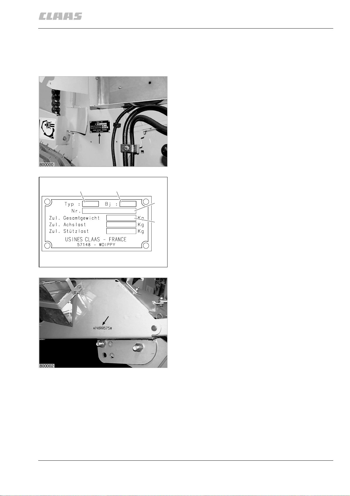
When ordering spare parts or if you have any technical
questions please provide the machine number of the
round baler together with the respective serial number.
This is absolutely necessary in order to avoid wrong
spare parts deliveries.
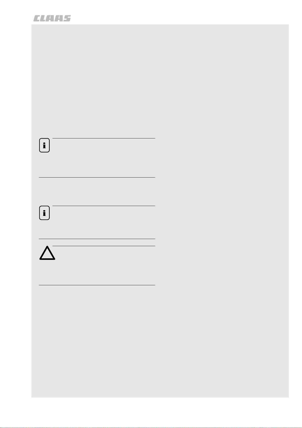
Type pl ate (baler)
The identification plate with the machine number is
fastened to the right hand side panel of the machine
above the wheel.
A=Type
B = Year of construction
C = Machine number
D = Permissible total weight
(Fig. 1, 2)
1
800001
A B
C
D
2
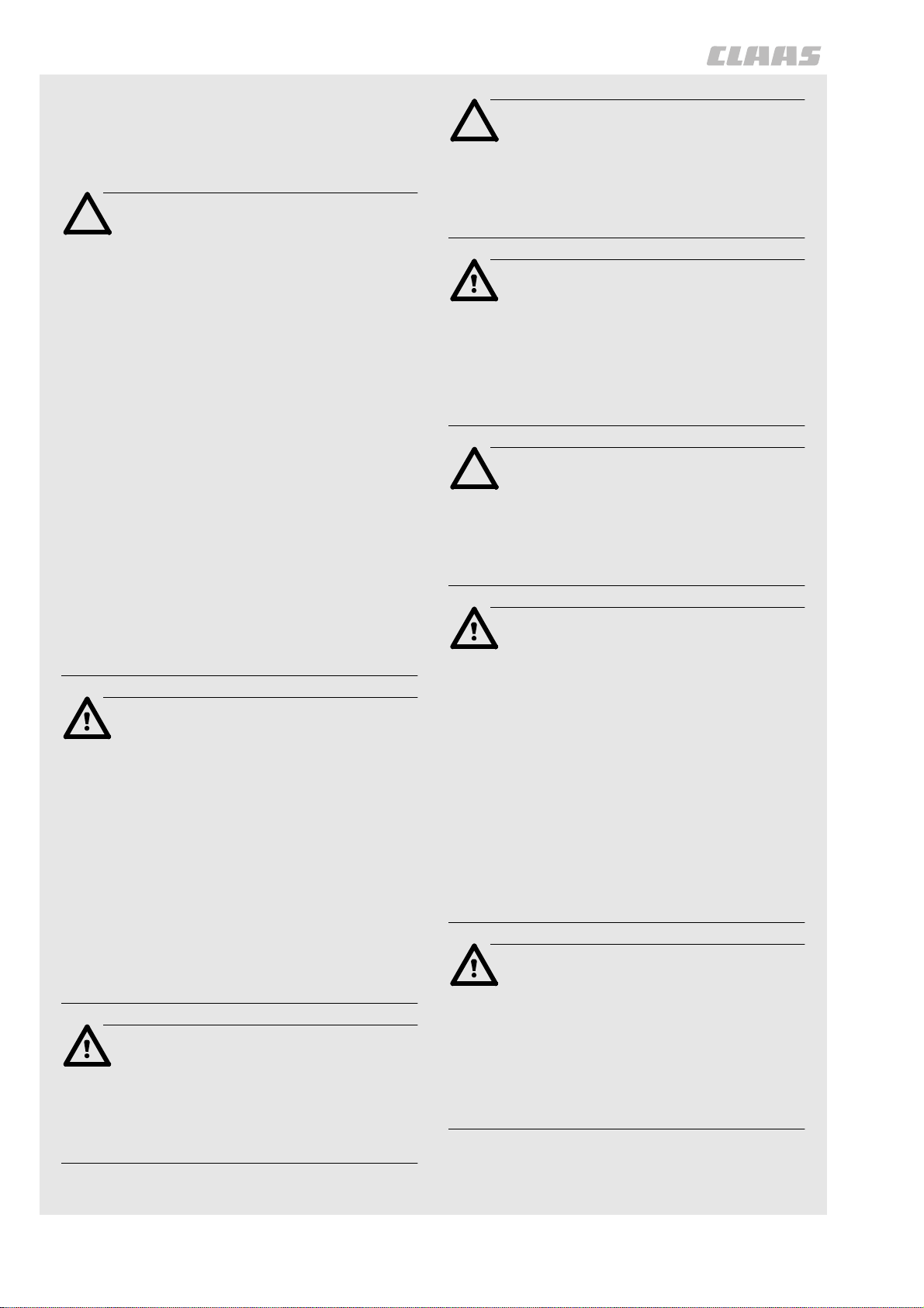
Machine serial number
The machine serial number is also engraved on the
front right of the platform.
(Fig. 3)
3
000 299 119 5 - BA ROLLANT 240 - 250 - 254 - 255 3.3.1
Page 20

General notes
3.3.2 BA ROLLANT 240 - 250 - 254 - 255 - 000 299 119 5
Page 21

4
Safety precautions
Page 22

Page 23
Safety precautions
Safety precautions
SAFETY PRECAUTIONS
For your safety, and those working with you, follow
these safety precautions and observe all safety
signs on the machine.
In order to provide a better view, certain
photographs or illustrations in this manual may
show an assembly with the safety shield removed.
However, a machine should never be operated in
this condition. Keep all shields in place. If shield
removal becomes necessary for repairs, replace
shield prior to machine operation!
Replace any Danger, Warning, Caution or
Instruction Safety signs that are missing or not
readable. Location of safety signs are indicated
within this manual.
Note!
The figure in () refers to the adjacent picture
and indicates the correct location of the
safety sign on the machine.
Personal inj ury ma y result if these safety precautions are not followed
• MAKE SURE no person is allowed on any part
of the Baler when tractor is running.
• MAKE SURE all safety shields and covers are
installed properly when Baler is operating.
• MAKE SURE all bystanders are in a safe
position before starting the tractor or operating
Baler.
• MAKE SURE the pickup head is fully lowered
before any part of the hydraulic system is
disconnected.
• MAKE SURE no one is allowed under the
pickup head unless the pickup head is in
transport position and securely locked.
• MAKE SURE all safety shields on Baler are in
place and secured when any have been
removed for servicing, to make adjustments,
etc. Remember, these shields are provided for
the protection of those working on or around
the Baler.
When parts are replaced that have safety signs,
make sure you install a new safety sign with each
new part.
Note!
New safety signs are available from your
CLAAS Dealer.
Attention!
Before using the machine read and
understand Operator’s Manual safety
messages!
Read and understand all safety signs on the
machine.
Learn and practice safe use of controls before
operating.
It is your responsibility to understand and follow
manufacturers instructions on machine operation,
service, and to observe pertinent laws and
regulations.
Operator Manuals may be obtained from your
CLAAS Dealer.
• NEVER STAND in path of Baler while
operating.
• KEEP OUT of Baler compartment while
operating.
• BE SURE all hydraulic fittings are tightened
securely whenever they have been loosened or
disconnected. Replace all hoses which have
become frayed. Escaping hydraulic oil under
pressure can cause personal injury.
• If Baler hydraulic system is equipped with an
accumulator, accumulator shutoff valve must be
closed before: (a) any part of the hydraulic
system is loosened or is to be disconnected,
and (b) the Baler is to be transported for any
distance.
• T AKE NO TE that hydraulic fluid under pressure
escaping from a very small hole can be almost
invisible. Use a small piece of cardboard or
wood to search/check for possible leaks.
• NEVER use your hands to detect pressure
leaks.
• CONSULT A DOCTOR immediately if you
sustain an injury by escaping fluids. Serious
infection or reactions can develop if proper
medical treatment is not administered quickly.
• MAKE SURE all oil or grease is removed from
operator’s ladder and platform and other
access areas immediately if any is spilled.
000 299 119 5 - BA ROLLANT 240 - 250 - 254 - 255 4.1.1
Page 24
Safety precautions
• BE EXTRA CAREFUL to keep hands, feet and
loose clothing away from moving parts.
• READ THIS MANUAL and take note of ALL
safety precautions included herein.
Attention!
Do not remove, install or make repairs to a
tire on a rim. Take tire and rim to the
nearest available tire specialist, who have
experience and the safety tools. If the tire
is not correctly positioned on the rim, or
the tire pressure is too high then the tire
bead is liable to loosen on one side,
resulting in the pressured air to leak out at
high speed and with force. This can lead
to the risk of the tire flying off and causing
serious injury!
Attention!
To provide more secure hand and foot
mobility, preventing slipping and possible
injury, always face the machine when
mounting and dismounting.
Danger!
Never operate the engine in a closed
building. Proper ventilation is required
under all circumstances.
Contact with belts, chains etc. can cause
injury. Keep clear.
A tire can explode during inflation and
cause serious injury or death. Never
increase air pressure beyond 35 PSI to
seat the bead on the rim. Replace a tire if
it has a defect. Replace a wheel rim which
has cracks, wear or severe rust. Make
sure that all the air is removed from a tire
before removing the tire from the rim.
Never use force on an inflated or partially
inflated tire. Make sure the tire is correctly
seated before inflating.
Danger!
Check the machine for leaks or any parts
that are broken, not working correctly, or
missing. Before you start the machine,
tighten all caps, dipsticks, battery covers,
etc.
Never use gasoline, naphtha or any other
volatile material for any cleaning
purposes. These materials may be toxic
and/or flammable.
Attention!
To help prevent personal injuries during
operation and maintenance, loose shirts,
sleeves or jackets must never be worn by
the operator.
Danger!
Before starting the tractor, be sure all
operating controls are in neutral. This will
ease starting loads on the starter and
batteries of the tractor and will eliminate
the accidental start up of power driven
equipment.
Travel speed should be such that
complete control and machine stability is
maintained at all times. Where possible,
avoid operating near ditches,
embankments and holes. Reduce speed
when turning, crossing slopes, and on
rough, slick, or muddy surfaces.
Use only metric tools. Other tools may not
fit properly. They may slip and cause
injury.
Danger!
Before leaving the tractor, stop the engine,
and remove the starter key. The gear shift
lever must be in neutral and the parking
brake engaged.
4.1.2 BA ROLLANT 240 - 250 - 254 - 255 - 000 299 119 5
Danger!
On highways use lighting equipment
according to local laws. Keep SMV
emblem clean and visible. Replace SMV
emblem when damaged or sun faded.
Stop, look and listen before entering
public thoroughfare or a highway.
Page 25
Attention!
Safety precautions
Safety signs
Collision of high speed road traffic and
slow moving machines can cause
personal injury or death.
Stay off slopes too steep for safe
operation. Shift down before you start up
or down a hill with heavy load. Avoid ”free
wheeling”.
Danger!
Provide a first aid kit for use in case of
accident.
As a safety precaution, it is suggested one or
more fire extinguishers be carried on the Baler
at all times. Fire extinguishers must be
purchased from Fire & Safety equipment supply
store.
Attention!
Look for this symbol to point out important
safety precautions. It means BECOME
ALERT! YOUR SAFETY IS INVOLVED.
This machine is of metric design.
Measurements in this manual are metric
with the customary U.S. measurements
following. Use only metric hardware and
tools as specified.
Attention!
Install new safety signs if the old safety
signs are destroyed, lost, painted over or
can not be read. When parts are replaced
that have safety signs, make sure you
install a new safety sign with each new
part.
Note!
New safety signs are available from your
Dealer or write to:
CLAAS OF AMERICA Inc.
P.O.Box 3008
3030 Norcross Drive
Columbus Indiana 47201
USA.
Transporting baler on a public thoroughfare
Whenever a Baler is to be transported on a public
thoroughfare, the following preparation of the Baler
should be made:
• Position pickup in the transport position. Close
gate, raise pickup and converging wheels, if
equipped.
• Make sure warning devices, such as slow
moving vehicle emblem, reflectors, etc., are
installed, clean and are in good condition.
Replacement Parts:
– When replacement parts are necessary for
periodic maintenance and servicing, genuine
CLAAS replacements must be used to restore
your equipment to original specifications.
– CLAAS will not claim responsibility for usage of
unapproved parts and/or accessories and
damages as a result of their usage.
• Use flashinglights according to local laws. Keep
SMV emblem clean and visible. Replace SMV
emblem when damaged or sun faded.
• For reference purposes, measure the overall
width and height of the Baler. These
measurements are particularly important for
transporting along narrow roads and where
underpasses may be encountered.
• If the Baler hydraulic system is equipped with
an accumulator, make sure the accumulator
shutoff valve is closed.
000 299 119 5 - BA ROLLANT 240 - 250 - 254 - 255 4.1.3
Page 26

Safety precautions
Danger!
Proper tire pressure should be maintained
at all times to insure stability during road
travel.
Always use a safety chain while
transporting baler. Sudden jolts or rocking
could cause the drawbar to break. If a
rocking motion occurs when transporting,
reduce speed until rocking stops. Check
rear tractor wheels for any tire tread wear
or pressure loss. Refer to operator’s
manual for tractor tire pressures.
Use care when towing baler at transport
speeds. Reduce speed if the weight of
baler exceeds weight of tractor.
When towing baler on public roads, an
extended mirror to improve visibility of
traffic behind the baler is recommended.
Mirrors are available from your dealer.
When the Baler is being transported on a public
thouroughfare, the following precautions must be
observed:
• Reduce speed before applying the brakes.
Using a hydrostatic transmission to slow the
vehicle is more effective than merely applying
the brakes.
If in doubt regarding local or state/provincial laws
pertaining to transportation of farm equipment,
consult your local law enforcement agency.
Danger!
Use or warning lights and turn signals are
recommended when transporting this
equipment on public roads, unless
prohibited by state or Local Laws.
A safety lighting kit is available from your
CLAAS dealer.
☞ Always use a safety chain when
transporting baler on public roads.
Transporting baler at speeds in excess
of 20 mph (32 km/h) is not
recommended.
Use care when towing baler at transport
speeds. Reduce speed if the combined
weight of baler with bale exceeds weight
of tractor. The approved minimal total
weight of tractor must not receed 2.5 tons
(2500 kg).
The towed baler can be transported
without brakesystem, when the approved
minimal total weight of tractor is 2.5 tons
(2500 kg).
Note!
Install new safety signs if the old are
destroyed, lost, painted over or can not be
read. When parts are replaced that have
safety signs, make sure you install a new
safety sign with each new part.
New safety signs are available from your
Dealer or write to:
CLAAS OF AMERICA Inc.
P.O. Box 3008
3030 Norcross Drive
Columbus Indiana 47201
USA
TO SHOW TECHNICAL DETAILS OF BALER
COMPONENTS AND ASSEMBLIES IN THIS
OPERATOR’S MANUAL, A NUMBER OF SAFETY
SHIELDS AND PANELS WERE REMOVED FOR
PHOTOGRAPHIC PURPOSES O NLY. ALL
SAFETY SHIELDS AND PANELS MUST BE
INSTALLED BEFORE BALING OPERATIONS
COMMENCE.
4.1.4 BA ROLLANT 240 - 250 - 254 - 255 - 000 299 119 5
Page 27
Safety precautions
Safety precautions
TRANSPORTING BALER ON A PUBLIC THOROUGHFARE
Attention!
When transporting the baler on a highway
use SMV emblem (PN 514 155.1).
Recommended warning lights
1
Attention!
Use of flashing warning lights and turn
signals are recommended when towing this
equipment on public roadfs unless prohibited
by state or local regulations. An implement
safety lighting kit is available from your
Dealer.
800297
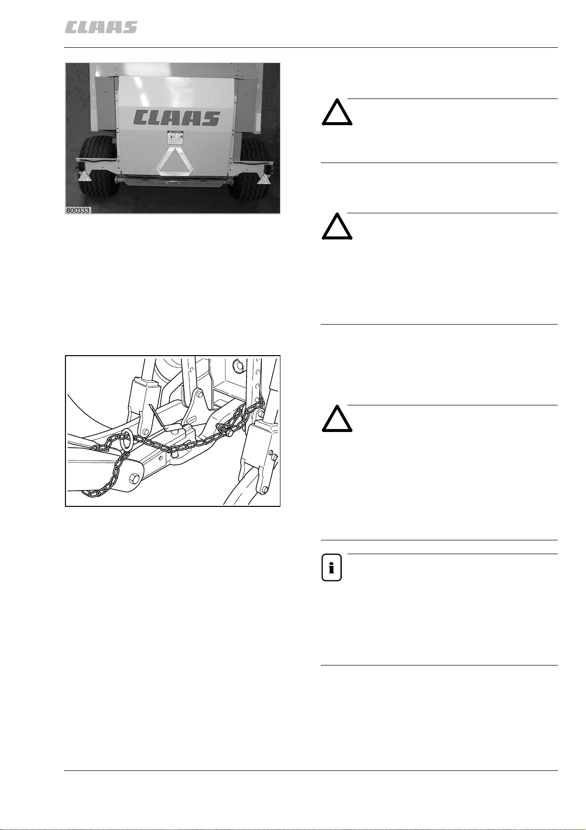
Preparing for transport
Close gate, raise pickup and converging wheels, if
equiped.
Attention!
Always use a safety chain while transporting
baler. Sudden jolts or rocking could cause
the drawbar to break. If a rocking motion
occurs when transporting, reduce speed until
rocking stops. Check rear tractor wheels for
2
any tire tread wear or air pressure loss.
Refer to operator’s manual for tractor tire
pressures.
Note!
Route safety chain from baler through hitch and
secure to drawbar supporting structure as
shown. Remove all slack except what is needed
for turns. Do not make sharp turns when
transporting baler. Damage could result if
tongue strikes tractor tire.
000 299 119 5 - BA ROLLANT 240 - 250 - 254 - 255 4.1.5
Page 28

Safety precautions
Danger!
Do not secure baler safety chain to drawbar.
Use care when towing baler at transport
speeds. Reduce speed if the combined
weight of baler with bale exceeds weight of
tractor. The approved minimal total weight of
tractor must not receed 2.5 tons (2500 kg).
The towed baler can be transported without
brakesystem, when the approved minimal
total weight of tractor is 2.5 tons (2500 kg).
4.1.6 BA ROLLANT 240 - 250 - 254 - 255 - 000 299 119 5
Page 29

Safety signs
Page 30

Page 31

1
1
2
4
514 432.2 (1)
(Fig.1,2,3,4)
1
3
000 299 119 5 - BA ROLLANT 240 - 250 - 254 - 255 4.2.1
Page 32

3
3
3
514 959.0 (3)
5
(Fig.5,6,7,8)
6
8
7
4.2.2 BA ROLLANT 240 - 250 - 254 - 255 - 000 299 119 5
Page 33

4
4
9
13
514 545.1 (4)
(Fig. 9, 10, 11, 12, 13)
10
4
4
11
4
4
12
000 299 119 5 - BA ROLLANT 240 - 250 - 254 - 255 4.2.3
Page 34

4
4
4
4
14
16
514 545.1 (4)
(Fig.14,15,16)
15
4.2.4 BA ROLLANT 240 - 250 - 254 - 255 - 000 299 119 5
Page 35

5
18
514 847.2 (5)
(Fig. 17, 18)
17
000 299 119 5 - BA ROLLANT 240 - 250 - 254 - 255 4.2.5
Page 36

6
19
20
514 848.1 (6)
(Fig. 19, 20)
4.2.6 BA ROLLANT 240 - 250 - 254 - 255 - 000 299 119 5
Page 37

7
7
7
21
22
25
514 551.1 (7)
(Fig. 21, 22, 23, 24, 25)
23
7
24
000 299 119 5 - BA ROLLANT 240 - 250 - 254 - 255 4.2.7
Page 38

7
Rollant 250 / 255 RC Comfort
7
26
27
28
514 551.1 (7)
(Fig.21,22,25)
4.2.8 BA ROLLANT 240 - 250 - 254 - 255 - 000 299 119 5
Page 39

9
WHEEL BOLTS OR NUTS MUST BE RETORQUED
AFTER 1 HOUR OF OPERATION AND THEN AFTER
EACH 10 HOURS OF OPERATION FOR THE FIRST
50 HOURS ON NEW MACHINES OR WHEN WHEELS
ARE REMOVED AND REPLACED.
514 553.2
31
9
29
30
514 553.2 (9)
(Fig.29,30,31)
000 299 119 5 - BA ROLLANT 240 - 250 - 254 - 255 4.2.9
Page 40

32
33
514 424.2 (12)
(Fig. 32, 33)
4.2.10 BA ROLLANT 240 - 250 - 254 - 255 - 000 299 119 5
Page 41

13
34
13
37
514 958.0 (13)
(Fig.34,35,36,37)
35
13
36
000 299 119 5 - BA ROLLANT 240 - 250 - 254 - 255 4.2.11
Page 42

514 961.0 (14)
42
14
14
14
(Fig. 38, 39, 40, 41, 42)
38
39
40
14
41
4.2.12 BA ROLLANT 240 - 250 - 254 - 255 - 000 299 119 5
Page 43

15
44
514 155.1 (15)
43
(Fig. 43, 44)
000 299 119 5 - BA ROLLANT 240 - 250 - 254 - 255 4.2.13
Page 44

16
16
45
46
47
515 400.0 (16)
(Fig.45,46,47)
4.2.14 BA ROLLANT 240 - 250 - 254 - 255 - 000 299 119 5
Page 45

Rollant 240
Rollant 250
18
48
52
515 398.0 (18)
(Fig. 48, 49, 50, 51, 52)
18
49
Rollant 255
18
50
18
51
000 299 119 5 - BA ROLLANT 240 - 250 - 254 - 255 4.2.15
Page 46

Rollant 240
56
Rollant 250
Rollant 255
88
88
514 474.0 (88)
(Fig. 53, 54, 55, 56)
53
54
88
55
4.2.16 BA ROLLANT 240 - 250 - 254 - 255 - 000 299 119 5
Page 47

93 93
57
58
353 078.0 (93)
(Fig. 57, 58)
000 299 119 5 - BA ROLLANT 240 - 250 - 254 - 255 4.2.17
Page 48

95
59
60
516 171.0 (95)
(Fig. 59, 60)
4.2.18 BA ROLLANT 240 - 250 - 254 - 255 - 000 299 119 5
Page 49

62
96
514 402.0 (96)
(Fig. 61, 62)
61
000 299 119 5 - BA ROLLANT 240 - 250 - 254 - 255 4.2.19
Page 50

97
63
64
955 917.2 (97)
(Fig. 63, 64)
4.2.20 BA ROLLANT 240 - 250 - 254 - 255 - 000 299 119 5
Page 51

5
Specifications
Page 52

Page 53

Specifications
CLAAS ROLLANT 240/250/ROLLANT 250/254/255 RC
Specifications are determined on a machine equipped with 11.5/80 – 15.3 8 PR tires.
Specifications
Castor gauge Rollant 240
Rollant 250
Rollant 254
Rollant 250/255 RC
PTO speed optional equipment 540 rpm or 1000 rpm (only Rollant 254/255)
Minimum PTO torque with 540 rpm
with 1000 rpm
Universal drive shaft Cam-type cut-out clutch or shear bolt coupling
Type on tractor
on machine
Hitching Drawbar for top and bottom
Traktor from 52 KW (70 hp)
Traktor from 59 KW (80 hp)
Traktor from 59 KW (80 hp)
Traktor from 70 KW (95 hp)
1750 Nm (1286.8 ft lb) (Rollant 240/250 and Rollant 255
up to machine serial no. 74800729)
1900 Nm (1397.1 ft lb) (Rollant 255 from machine
serial no. 74800730 and for Rollant 254 from machine
serial no. 75400036)
1200 Nm (882.4 ft lb) (for Rollant 250 from machine
serial no. 72500711, for Rollant 255 up to machine
serial no. 74801818)
1350 Nm (992.7 ft lb) (for Rollant 254 from machine serial
no. 75400036, for Rollant 255 from machine
serial no. 74801819)
Wide angle joint
Free-wheeling device
(top = top-fitted tow jaw*; bottom = swinging drawbar)
* in Germany only permissible with design-specific
type-approved drawbar
* in Italy only permitted with a swivelling drawbar
Load on drawbar 510 kg (1124.3 pd) at hitch eye
Jack stand Adjustable for height by hand crank and jack stand
extension
Feeder mechanisms
Pickup 2.10 m Working width
Tine carriers
Tines
Space between tines
Lift
Height adjustment
Pickup 1.85 m Working width
Tine carriers
Tines
Space between tines
Lift
Height adjustment
Optional equipment Ground guide
optionally
Feed
Wheels for pickup 16 x 6.50 - 8 6 PR 2.1 bar (30.5 psi)
Tightening torque for castor
gauge wheel screws 83,5 Nm (61.4 ft lb)
2100 mm (83 inch)
4
16 per row
61 mm (2.4 inch)
hydraulic
by locking device on hydraulic cylinder
1850 mm (71 inch)
4
14 per row (2.4 inch)
61 mm
hydraulic
by locking device on hydraulic cylinder
2 rigid castor gauge wheels
2 castor gauge wheels
Short-crop baffle
000 299 119 5 - BA ROLLANT 240 - 250 - 254 - 255 5.1.1
Page 54

Specifications
CLAAS ROLLANT 240/250/ROLLANT 250/254/255 RC
Method of loading the bale
chamber:
ROLLANT 250/254/255 RC
ROLLANT 250
ROLLANT 240
Reversing Manual reversing (optional for Rollant 240/250/254/255)
Cutting unit
(ROLLANT 250/255 RC)
Bale chamber Diameter
Width
Bale-forming rollers Quantity
Diameter
Drive 1" and 1
Tailgate Opened and closed from tractor via dual operation control
Bale density Adjustable via the hydraulic pressure control valve. Also
Forced feed by cutting rotor
Forced feed by feed pump or reel
Forced feed by feed pump or reel
or hydraulically from tractor (optional for Rollant 250/254/
255)
or hydraulically from control panel or Claas
Communicator (optional for Rollant 254/255)
Knives 14
Shortest cut length approx. 70 mm (27.5 inch)
Engaging and disengaging the knives via control box and/
or control terminal or Claas Communicator
(high-convenience operation)
1250 mm (49 inch)
1200 mm (47 inch)
16
308 mm (12 inch) (roller 1)
267 mm (11 inch) (roller 2 - 16)
1
/4" steel roller chains (reinforced for the Rollant
255) with automatic chain lubrication.
valve; optionally via the control panel/Claas
Communicator on the Rollant 254/255.
with oscillating section (not for the Rollant 240).
Wrapping unit
Automatic and manual
ROLLATEX net
wrapping system
Spare net roll 1 net roll in swivel-type holder
Automatic double
twine tying operation
Twine Sisal
Twine box 4 balls of twine
Standard "Automatic" or "manual" operating mode and adjustable
High Convenience
Operation
(optional for Rollant
255)
Standard Adjustable number of twine wraps
High Convenience
Operation
(optional for Rollant
255)
Plastic
Net and/or twine wrapping
Automatic twine wrapping
number of net wraps
1.6 / 2.2 / 2.9 / 3.5 / 4.1
1.3 / 1.9 / 2.5 / 3.2 / 3.8
From 1.25 to 4.5 in increments of 0.25
1.25 / 1.5 / 1.75 / 2.0 / 2.25 / through / 4.5 wrappings
14 / 17 / 19 / 22
From 12 to 30 in increments of 2
12 / 14 / 16 / 18 / 20 / through / 30 wrappings
200 to 330 m/kg (7874 to 12992 inch/pd)
400 to 750 m/kg (15748 to 29527 inch/pd)
5.1.2 BA ROLLANT 240 - 250 - 254 - 255 - 000 299 119 5
Page 55

CLAAS ROLLANT 240/250/ROLLANT 250/254/255 RC
Specifications
Wheels
Gauge wheels for pick-up 296 Nm (217.6 ft lb)
Tires
11.5/80 - 15.3 8 PR
15.0/55 - 17 10 PR
19.0/45 - 17 10 PR
500/45 - 22.5 8 PR
Hydraulic system
For CLAAS Control Terminal
(CCT) models or hydraulic rotor
reverse
Air pressure
2.0 bar (29 psi) (Rollant 240/250)
2.0 bar (29 psi) (Rollant 240/250/254/255)
2.0 bar (29 psi) (Rollant 240/250/254/255)
1.7 bar (25 psi) (Rollant 254/255)
2 double-acting hydraulic cylinders for tailgate
1 single-acting hydraulic cylinder for pick-up lift
mechanism
2 single-acting hydraulic cylinders for cutting mechanism
1 double-acting hydraulic cylinder for hydraulic rotor
reverse
Required tractor hydraulics
Standard balers 1 double-acting control valve with auxiliary hydraulic
outlets is required for the tailgate latches
1 single-acting control valve with auxiliary hydraulic outlet
is required for the hydraulic pick-up lift mechanism or for
engaging / disengaging the knives
1 double-acting control valve for hydraulic reversing of
rotor (option)
CCT balers 1 single-acting control valve with auxiliary hydraulic outlet
1 quick-release coupling socket so oil returns to the
hydraulic tank without pressure (included in delivery)
Flow rate of hydrau lic oil
Standard
For CCT model
Hydraulic pressure
Maximum oil temperature 80 °C (176 °F)
Maximum 80 liters (21 US gal)/ minute
Maximum 80 liters (21 US gal)/ minute
Maximum 230 bar (3336 psi),
Minimum 130 bar (1885 psi)
Electrical systems
Required tractor electrical
systems
7-pin socket for lighting equipment
2-pin appliance socket (12 Volt) with 25 A in-line fuse
10.5 - 16.5 V
Weights
Basic machine
with twine and net wrapping
with gauge wheels for pick-up
Permissible maximum weight for
CCT model 2970 kg (6548 pd)
2680 kg (5908 pd)
+ 40 kg (+88 pd)
000 299 119 5 - BA ROLLANT 240 - 250 - 254 - 255 5.1.3
Page 56

Specifications
CLAAS ROLLANT 240/250/ROLLANT 250/254/255 RC
Dimensions of the round baler
Width B Width over tires for 11.5/80 - 15.3 8 PR
for 15.0/55 - 17 10 PR
for 19.0/45 - 17 10 PR
for 500/45 - 22.5 8 PR
2.10 m pick-up See width above the tires (pickup castor
wheels in parking position on tailgate. See
"After use")
1.85 m pick-up Width over pick-up wheels, fixed
Width over pick-up castor wheels
Height H for 11.5/80
for 15.0/55
for 19.0/45
for 500/45
Length L from hitch eye of baler drawbar to rear
edge of machine
with bale discharge ramp fitted
with tailgate opened
Track width width over tires for 11.5/80 - 15.3 8 PR
Upper drawbar 4338 mm (171 inch)
for 15.0/55 - 17 10 PR
for 19.0/45 - 17 10 PR
for 500/45 - 22.5 8 PR
2310 mm (91 inch)
2400 mm (95 inch)
2570 mm (97 inch)
2580 mm (102 inch)
2574 mm (102 inch)
2652 mm (104 inch)
2310 mm (91 inch)
2310 mm (91 inch)
2310 mm (91 inch)
2389 mm (94 inch)
4726 mm (186 inch)
5058 mm (199 inch)
2020 mm (80 inch)
2010 mm (79 inch)
2080 mm (82 inch)
2080 mm (82 inch)
5.1.4 BA ROLLANT 240 - 250 - 254 - 255 - 000 299 119 5
Page 57

CLAAS ROLLANT 240/250/ROLLANT 250/254/255 RC
SAFETY FEATURES
Specifications
Shear bolts Universal drive shaft
(optional)
Pick-up drive 1 hex nut M 8 x 60 ISO 8676-8.8
Hydraulic rotor reverse
backwinding mechanism
(optional equipment or for
CCT model)
Overload protection Universal drive shaft
(optional equipment)
1 hex bolt M 8 x 60 ISO 8676-8.8
1 self-locking nut VM 8 tightening torque 24.5 Nm (18.0 ft lb)
1 self-locking nut VM 8 tightening torque 24.5 Nm (18.0 ft lb)
1 hex nut M 8 x 70 ISO 8676-10.9
1 washer 8.4 x 23 x 3
1 washer A 8
1 hex nut M 8
Cam-type cut-out clutch
– 1750 Nm (1286.8 ft lb) (at 540/rpm) -
Rollant 240/250 and
Rollant 255 up to machine serial no. 74800729
– 1900 Nm (1397.1 ft lb) (at 540/rpm) -
Rollant 255 from machine serial no. 74800730
– 1200 Nm (882.4 ft lb) (at 1000/rpm) -
Rollant 250 from machine serial no. 72500011,
Rollant 255 up to machine serial no. 74801818
– 1350 Nm (992.7 ft lb) (at 1000/rpm) -
Rollant 254 from machine serial no. 75400036,
Rollant 255 from machine serial no. 74801819
000 299 119 5 - BA ROLLANT 240 - 250 - 254 - 255 5.1.5
Page 58

Specifications
5.1.6 BA ROLLANT 240 - 250 - 254 - 255 - 000 299 119 5
Page 59

6
Description and function
Page 60

Page 61

Description and function
Description and function
T ransmission of power
The baler is driven by a wide angle universal drive
shaft with a PTO speed of 540* rpm or 1000* rpm.
The tractor end of the universal drive shaft is fitted with
a wide angle universal joint. The machine end of the
shaft is fitted with a free-wheeling device and an
overload clutch or shear bolt*.
*Optional equipment
Pick-up
The pick-up gathers the crop tidily. The crop guard or
baffle plate ensures uniform intake. The crop gathered
by the pick-up is conveyed to the center by lateral feed
augurs and then taken up by the rotor, i.e. rapid
removal from the pick-up.
Crop guard
The crop guard is located above the pick-up and
assists in the intake of the crop.
Baffle plate
The baffle plate prevents the pick-up from entraining
1
short stalks, windrow, and aftermath.
Roller crop guard
The roller crop guard guarantees an even feed of the
rotor even with unfavourable harvesting conditions,
uneven swaths and short crops.
Cutting unit
(ROLLANT 250/254/255 RC)
The cutting unit cuts the crop to lengths of approx.
70 mm before it is fed into the bale chamber.
000 299 119 5 - BA ROLLANT 240 - 250 - 254 - 255 6.1.1
Page 62

Description and function
Rotor backwinding unit
(ROLLANT 240/250/254/255)
Blockages in the bale chamber can be removed by
reversing the rotor (See section on "Manual rotor
reverse device").
Hydraulic rotor reverse device
(ROLLANT 254/255 with control panel)
The rotor can be hydraulically reversed to clear
blockages.
Hydraulic rotor reverse device from tractor
(ROLLANT 250/254/255)
The rotor can be hydraulically reversed to clear
blockages.
Bale chamber
The bale chamber is filled with loose crop by means of
the rotor of the cutting device and/or the feed rake.
The oscillating section is located at the upper part of
the baling chamber. When bale compaction starts, it
rises up and into the bale compaction chamber and
thus begins the rotation and compression of the bale at
2
an early stage as the chamber is filled (not for Rollant
240).
The material rotates inside the bale chamber, made up
of 16 steel rollers and is compressed layer by layer
into a round bale.
The round bale is then compressed from inside to
outside.
The oscillating section increases the pressure as it
presses on the surface of the bale and moves
outwards as the diameter of the bale increases (not for
Rollant 240).
Wrapping
When the bale has the required density, it is
automatically wrapped with net or twine. With net
wrapping, »automatic wrapping« or »manual
wrapping« operating modes can be chosen. The bale
is ejected into the field after the tailgate opens.
6.1.2 BA ROLLANT 240 - 250 - 254 - 255 - 000 299 119 5
Page 63

Description and function
Bale discharge ramp
The bale discharge ramp is equipped with a warning
device. A sensor sounds a warning signal and the
control lamp on the control box lights up. On CCT
models the control terminal displays the bale
discharge.
Bale transport
See »Specifications« for the bale weights.
The round bales may be moved or loaded with
front-end loaders or suitable rear-mounted loaders.
Storage of round bales
Bales produced by the CLAAS ROLLANT 240/250 and
250/254/255 RC are to a great degree protected from
the effects of the weather. Bales wrapped in netting
are particularly well protected. Even very heavy rain
will penetrate the bale only to a minor degree.
000 299 119 5 - BA ROLLANT 240 - 250 - 254 - 255 6.1.3
Page 64

Description and function
6.1.4 BA ROLLANT 240 - 250 - 254 - 255 - 000 299 119 5
Page 65

7
Prior to operation
Page 66

Page 67

Prior to operation
Prior to operation
CHECK AND OBSERVE BEFORE STARTING OPERATION
1. Remove or unpack all parts fastened with wire
and/or packed with the machine.
2. With the ROTO CUT version withdraw dummy
knives and dummy knife holder from the twine
box. Install dummy knife holder on the platform.
3. For the use of the round baler the tractor must be
equipped with a double-acting control valve and
two hydraulic ports with quick couplings.
4. An additional single-acting control valve with
quick-release coupling must be available for the
hydraulic-operated pick-up and to engage and
disengage the knives (ROLLANT 250/254/255
RC).
5. For standard balers with hydraulic rotor reverse,
an additional double-acting control valve with
quick-release coupling is required.
6. For balers with CCT, a single-acting control valve
with quick-release coupling and a quick-release
coupling socket (included in delivery) is required,
so that oil can return to the hydraulic tank without
pressure. If necessary re-equip the tractor.
7. Attach the return line and the oil pressure line.
8. Check all the connections for seal integrity.
9. The power take-off speed must be 540 rpm or
1000 rpm.
10. Engage the tractor power take-off shaft only at low
idle speed.
11. When baling with the counterweight coupling
(check the model). Check for presence and
seating of the bushing in the drawbar eye.
12. Attach the round baler to the trailer coupling ring
of the tractor.
Hitch up only balers with type-approved draw
bar to the towing hitch.
13. Bring the parking jacks to the transportation
setting
14. Secure the propeller shaft guard against travelling
by attaching the chains.
15. After hitching up the round baler and connecting
the propeller shaft check whether the propeller
shaft is free to move by carefully driving right- and
left-hand turns.
16. The most favourable initial position of the pick-up
drum is 20 to 30 mm (0.79 to 1.2 inch) between
teeth and ground. In order to avoid damage to the
supporting wheels of the pick-up, these should be
slightly raised when working on hard stubbles.
17. In order to establish the electric power supply for
the round baler connect the 2-pole plug to the
socket on the tractor.
If the tractor is not fitted with a 2-pole socket, the
latter should be retrofitted.
The cable with the 25 A pendant fuse, which is
available under part number 011 708.0, must be
connected directly to the negative pole of the
tractor battery.
If the tractor has a 24 V starting system this cable
must only be connected to the battery linked to
frame ground. Fuses with ratings > 25 A are not
permitted.
18. Connect the 7-pole plug for the travel light to the
socket on the tractor and to the round baler.
19. Attach the connection cable on the control box or
the control panel to the 13-pin plug connector on
the round baler.
20. Position the control box and/or Control Terminal or
Claas Communicator on the tractor within easy
reach of the driver.
21. Close the tailgate before using the baler.
22. As a measure to avoid crumbling losses when
working with very dry and brittle baling material it
may be necessary to work with a low power
take-off shaft speed. When working with thin
swaths it may be necessary to increase the drive
speed.
23. Avoid idle drives with the power take-off shaft
running.
24. Round baler with net wrapping facility:
Remove the knife protection before starting the
machine for the first time.
000 299 119 5 - BA ROLLANT 240 - 250 - 254 - 255 7.1.1
Page 68

Prior to operation
25. Check wheel nuts or wheel studs for tight fit
(tightening torques see »Technical Data«). Check
the tire pressure, if necessary correct it as
specified in the »Tec h ni c al D at a «.
26. Whenever assembling wheels retighten the wheel
bolts after the first 10 operating hours, then check
for tightness every 50 operating hours. Tightening
torques see »Technical Data«.
Assembly of wheels is only permitted when using
lifting gear of appropriate load bearing capacity for
the total weight of the respective round baler type.
27. Check tension and condition of the chains.
28. Check the oil level in the angular drives.
29. Check the oil level in the chain lubrication tank.
30. Never let roundbaler run without supervision.
7.1.2 BA ROLLANT 240 - 250 - 254 - 255 - 000 299 119 5
Page 69

Prior to operation
Prior to operation
ATTACH THE BALER
Before hitching the propeller shaft, adjust the baler to
the tractor.
Danger!
Hitch the baler according to specifications.
Fasten and secure it only to the devices
provided and permitted for the purpose.
Always proceed very carefully when hitching
and unhitching the baler to/from the tractor.
1
To avoid damage to the propeller shaft and the drive, it
is essential to be aware of the precise hitch
dimensions to the tractor. To ensure safety while
driving, the coupling must be adjusted with the
counterweight pendant (see section on "Shortening
the propeller shaft").
S
The maximum travel round bends is defined by the
length - when telescoped in - of the propeller shaft "L".
(Fig. 1)
Connecting the universal drive shaft to the baler
To connect the universal drive shaft, unfasten the
quick-release couplers and pull back the guard (S).
Universal drive shaft with shear bolt coupling:
Push the locking pin (1) of the universal drive shaft.
Push the universal drive shaft onto the gearbox input
shaft. Push the universal drive shaft until the locking
pin locks securely into place on the notch on the shaft.
(Fig. 2, 3)
2
1
3
000 299 119 5 - BA ROLLANT 240 - 250 - 254 - 255 7.2.1
Page 70

Prior to operation
K
Universal drive shaft with taper lock
The CC taper lock creates a strong connection,
completely without backlash between the yoke of the
universal drive shaft and the PTO shaft.
The built-in spring ensures an optimum compensation
of tolerances. Any subsequent slackness caused by
the settling of the hub and the shaft is automatically
compensated for.
Fitting the drive shaft with the CC taper lock
Unscrew the taper lock (K).
Slide the universal drive shaft onto the gearbox input
shaft until the borehole for the taper lock and the notch
on the PTO stub shaft are aligned.
Screw in the taper lock (K) and tighten it.
Refit the guard (S).
(Fig. 4, 5)
S
W
B
4
5
Jack stand
Danger!
Before hitching or unhitching the baler, the
jack stand must be brought into the
appropriate position (to stand safely). Be
careful when using the jack stand – danger
of crushing!
Before you hitch the baler:
6
Bring the drawbar to the correct height using the winch
(W).
After hitching the baler, the jack stand needs to be
raised completely using the winch (W).
(Fig. 6)
7.2.2 BA ROLLANT 240 - 250 - 254 - 255 - 000 299 119 5
Page 71

B
Prior to operation
Loosen bolt (B), pull it out and then pull the support out
forwards. Rotate the parking jack upwards by 180° and
push back in. Reinsert the bolt (B) and secure with a
W-clip.
(Fig. 6, 7)
Danger!
The work of converting the height of the
drawbar hitching (e.g. changing from top to
bottom hitching or vice versa) must only be
7
Attaching to the swinging drawbar with a safety nut
The round baler must be connected horizontally to the
swinging drawbar of the tractor.
done by authorized workshops.
The height of the drawbar (Z) can be adjusted by
unscrewing bolts (1 and 2). Once the height of the
drawbar has been adjusted, loosen bolt (2) and adjust
the hitch eye so that it is parallel to the ground.
Tighten bolts (1 and 2) to the torques specified below.
(Fig. 8, 9)
8
Tightening torques:
Bolt (1)
M 20 x 1.5 x 65 ISO 8676-10.9 = 486 Nm (357.4 ft lb)
Bolt (2)
M 20 x 1.5 x 140 ISO 8676-10.9 = 486 Nm (357.4 ft lb)
Danger!
Retighten bolts (1 and 2) after the first 10
9
hours of operation; thereafter check the bolts
for tightness after every 50 hours of
operation.
000 299 119 5 - BA ROLLANT 240 - 250 - 254 - 255 7.2.3
Page 72

Prior to operation
1
10
Attaching to the swinging drawbar with a counter nut
Adjusting the length of the drawbar fork arms
The round baler must be hitched horizontally to the
trailer coupling on the tractor. The towing fork with
construction type approval M 9646 forms part of the
basic equipment of the machine.
The length of the arms of the towing fork are screwed
on to the left and right of the machine, in each case
using two mounting screws M20 x 1.5 x 65-10.9 (1),
two nuts and two counter nuts.
– Tightening torque (for the nuts) = 486 Nm
(357.4 ft lb)
– Tightening torque (for the counter nuts) = 300 Nm
(220.6 ft lb)
Attention!
1
11
Secure the baler so that it cannot roll away.
☞ Park the baler on support feet.
Attention!
Tighten up the fastening screws (1) after the
first 10 hours of operation, and then check
they are still fitting tightly after every 50 hours
of operation.
(Fig. 10, 11)
7.2.4 BA ROLLANT 240 - 250 - 254 - 255 - 000 299 119 5
Page 73

Z
2
Prior to operation
Adjusting the hitch eye
The hitch eye (Z) must be set up in a position parallel
with the ground.
The hitch eye is screwed onto the towing fork using a
screw type M20 x 1.5 x 160-10.9 (2), a nut and a
counter nut.
– Tightening torque (for the nut) = 486 Nm
(357.4 ft lb)
– Tightening torque (for the counter nut) = 300 Nm
(220.6 ft lb)
12
Attention!
Secure the baler so that it cannot roll away.
Z
2
☞ Park the baler on support feet.
Attention!
Tighten up the fastening screws (2) after the
first 10 hours of operation, and then check
they are still fitting tightly after every 50 hours
of operation.
13
Hitch up the baler and secure it.
(Fig. 12, 13)
Greasing the hitch eye
The sleeve of the hitch eye must be kept permanently
greased in order to prevent wear from friction.
000 299 119 5 - BA ROLLANT 240 - 250 - 254 - 255 7.2.5
Page 74

Prior to operation
Connecting the universal drive shaft to the tractor
(for swinging drawbar hitching)
Adjust the swinging drawbar of the tractor so that the
hitch point is located under the joint of the wide angle
universal drive shaft. Now hook up the baler.
Slide the universal drive shaft onto the splined PTO
stub of the tractor until the locking pin (T) engages
correctly in the groove of the PTO stub.
Always follow the maintenance regulations (see
"Lubrication schedule" section)
800024
14
(Fig. 14)
Check that the two halves of the propeller shaft are
intermeshed:
L
Z
First attach the two halves of the propeller shaft to the
tractor and the machine, so that the propeller shafts do
not push into one another, but are held alongside one
another.
When driving in a straight line, the propeller shaft pipes
should intermesh, but not hit at the ends "L
of telescoped propeller shaft, "P
P
U
When the tractor is turned as far left or as far right as it
" = profile cover).
U
" - length
Z
will go, the propeller shaft should be pushed out of the
15
profile cover (P
) by only one third when telescoped to
U
the shortest position (L
)(LB = maximum length at
z
turn).
If the two halves of the propeller shaft hit at the ends,
L
B
they must be shortened to the necessary length.
After shortening the propeller shaft, fit the two halves
to both the tractor and to the machine.
(Fig. 15, 16)
P
U
800025
16
Fasten the chains (G) of the universal drive shaft
guards with their hooks to the drawbar and to the
tractor.
Danger!
Never operate the baler without the universal
drive shaft guards (E and S). Safety hazard –
risk of injury!
S
(Fig. 14, 17)
17
7.2.6 BA ROLLANT 240 - 250 - 254 - 255 - 000 299 119 5
Page 75

A
B
Prior to operation
Shortening the propeller shaft
Hold the two halves of the propeller shaft against one
another at the shortest operating setting.
Mark a dimension of 40 mm (1.57 in) (X) from the edge
(B) of the outer protective pipe (A) on the inner
protective pipe (C).
(Fig. 18)
C
C
X
D
D
18
Dismantle the protective pipes.
Cut the outer protective pipe (A) at the marked spot.
Hold the cut section (D) against the inner protective
pipe (C) and cut off the same length on the inner
protective pipe.
(Fig. 19)
19
Shorten the outer profile pipe (E) and the inner profile
pipe (F) by the same length as the cut off section (D)
from the outer protective pipe (the inner profile pipe is
hardened).
Smooth the cut edges (deburr) and carefully remove
the chips.
Grease the propeller shaft once pushed together.
Attention!
E
20
(Fig. 20, 21)
Insufficient grease on the profile pipe will
reduce the service life of the propeller shaft.
F
D
21
000 299 119 5 - BA ROLLANT 240 - 250 - 254 - 255 7.2.7
Page 76

Prior to operation
22
Danger!
The work of converting the height of the
drawbar hitching (e.g. changing from top to
bottom hitching or vice versa) must only be
done by authorized workshops.
Attaching to the jaw-type hitch with a safety
nut
(In Germany only permitted with type-approved
drawbar)
The round baler must be connected horizontally to the
top-fitted tow jaw of the tractor.
The height of drawbar (Z) can be adjusted after
removing bolts (1 and 2).
Once the height of the drawbar has been adjusted,
adjust the hitch eye so that it is parallel to the ground.
Tighten bolts (1 and 2) to the torques specified below.
23
Note!
When setting the drawbar, check that the
pick-up is set correctly (20 mm to 30 mm (0.79
to 1.18 in) distance between fork teeth and
ground) to ensure good removal of the baling
material.
(Fig. 22, 23)
Tightening torques:
Bolt (1)
M 20 x 1.5 x 65 ISO 8676 – 10.9 =
486 Nm (357.4 ft lb)
Bolt (2)
M 20 x 1.5 x 140 ISO 8676 – 10.9 =
486 Nm (357.4 ft lb)
Danger!
Retighten bolts (1 and 2) after the first 10
hours of operation; thereafter check the bolts
for tightness after every 50 hours of
operation.
(Fig. 22, 23)
7.2.8 BA ROLLANT 240 - 250 - 254 - 255 - 000 299 119 5
Page 77

1
1
24
Prior to operation
Attaching to the jaw-type hitch with a counter
nut
(in Germany only permitted with type-approved
drawbar)
Adjusting the drawbar fork arms
The round baler must be hitched horizontally to the
trailer coupling on the tractor. The towing fork with
construction type approval M 9646 forms part of the
basic equipment of the machine.
The length of the arms of the towing fork are screwed
on to the left and right of the machine, in each case
using two mounting screws M20 x 1.5 x 65-10.9 (1),
two nuts and two counter nuts.
– Tightening torque (for the nuts) = 486 Nm
(357.4 ft lb)
– Tightening torque (for the counter nuts) = 300 Nm
(220.6 ft lb)
Attention!
25
Secure the baler so that it cannot roll away.
☞ Park the baler on support feet.
Attention!
Tighten up the fastening screws (1) after the
first 10 hours of operation, and then check
they are still fitting tightly after every 50 hours
of operation.
(Fig. 24, 25)
000 299 119 5 - BA ROLLANT 240 - 250 - 254 - 255 7.2.9
Page 78

Prior to operation
Adjusti ng th e hitch eye
The hitch eye (Z) must be set up in a position parallel
with the ground.
Z
2
Z
The hitch eye is screwed onto the towing fork using a
screw type M20 x 1.5 x 160-10.9 (2), a nut and a
counter nut.
– Tightening torque (for the nut) = 486 Nm
(357.4 ft lb)
– Tightening torque (for the counter nut) = 300 Nm
(220.6 ft lb)
26
Attention!
Secure the baler so that it cannot roll away.
☞ Park the baler on support feet.
2
Attention!
Tighten up the fastening screws (2) after the
first 10 hours of operation, and then check
they are still fitting tightly after every 50 hours
of operation.
27
K
2
Hitch up the baler and secure it.
(Fig. 26, 27)
Set up ball head coupling
(only permitted in accordance with the customary local
laws)
The ball head coupling (K) must be set up in a parallel
position to the ground.
The ball head coupling is screwed to the towing fork
with a screw type M20 x 1.5 x 160-10.9 (2).
Tightening torque (for the nut) = 486 Nm
(357.4 ft lb)
Tightening torque (for the counter nut)= 300 Nm
(220.6 ft lb)
28
Attention!
Secure the baler to prevent it from rolling and
rest on its jack stand.
Tighten up the fastening screws (2) after the
first 10 hours of operation, and then check
they are still fitting tightly after every 50 hours
of operation.
(Fig. 26, 28)
Hitch up the baler and secure it.
7.2.10 BA ROLLANT 240 - 250 - 254 - 255 - 000 299 119 5
Page 79

29
Prior to operation
Attaching the universal drive shaft to the tractor
(for top-fitted tow jaw)
Slide the universal drive shaft onto the splined PTO
stub of the tractor until the locking pin (T) engages the
groove of the PTO stub correctly.
Hold the male and female sections of the universal
drive shaft side by side with the tractor turned sharply
to the right and left.
The sliding sections must overlap as far as possible at
this point, but must not collide when the universal drive
shaft is telescoped to its shortest position.
Note!
The overlap of the universal drive shaft must be
at least 200 mm (7.87 in) when travelling
straight ahead.
Shorten the sections of the universal drive shaft to the
required length if short hitch dimensions make it
necessary.
30
Note!
After cutting the sections of the universal drive
shaft to length, the cut surfaces must be
deburred.
After adaptation, connect the universal drive shaft to
the splined PTO stub of the tractor, making sure that
pin (T) locks into position correctly.
Fasten the chains (G) of the universal drive shaft
guards (E) to the drawbar and to the tractor with their
hooks.
The chain (K) is used to hold the universal drive shaft
when the baler is not connected to the tractor.
Before connecting the universal drive shaft, unhook
the chain (K) so that the universal drive shaft can
move freely.
(Fig. 29, 30)
000 299 119 5 - BA ROLLANT 240 - 250 - 254 - 255 7.2.11
Page 80

Prior to operation
7.2.12 BA ROLLANT 240 - 250 - 254 - 255 - 000 299 119 5
Page 81

Prior to operation
Prior to operation
ELECTRICAL SYSTEMS
Control box
Standard operation
Attach the mounting support supplied onto the tractor
at a position within reach of the driver.
For ROLLANT 240/250, insert control box (S) in the
bracket, for ROLLANT 254/255, insert control box (T)
in the bracket.
(Fig. 1, 2)
1
T
V
2
Control Terminal
Attach the mounting support supplied onto the tractor
at a position within reach of the driver.
As an option for ROLLANT 254/255, insert Control
Terminal (V) in the bracket
(Fig. 3)
3
Claas Communicator
Attach the bracket supplied for Claas Communicator
(B) to the tractor within the reach and vision of the
driver.
Insert the Claas Communicator into the bracket and
tighten wing nut.
(Fig. 4, 5)
B
4
000 299 119 5 - BA ROLLANT 240 - 250 - 254 - 255 7.3.1
Page 82

Prior to operation
D
B
Connect the 9-pole flat plug (D) of the Y-shaped cable
to the Claas Communicator.
(Fig. 5)
5
Baler connections
Connect the 9-pin plug (B) of the Y-shaped cable for
baler and Claas Communicator power supply to the
baler.
(Fig. 6)
A
6
Connections on the tractor:
Plug 2-pin connector (A) on the Y-shaped cable for
baler and Claas Communicator power supply into the
utility socket on the tractor.
(Fig. 7)
7
Power supply
Plug the 2-pin connector (3) into the implement socket
on the tractor for power supply to the baler.
Machines with lighting equipment
Plug the 7-pin connector (7) into the socket provided
for this purpose.
(Fig. 8)
8
7.3.2 BA ROLLANT 240 - 250 - 254 - 255 - 000 299 119 5
Page 83

Prior to operation
Prior to operation
HYDRAULIC SYSTEM
Hydraulic system for standard machines
Both male and female coupling (dust caps) of the
hydraulic lines between the tractor and the baler are
marked with different colors to avoid operating errors.
Black = Pick-up lift
Red = Tailgate, opening
Green = Tailgate, closing
1
Connect the hydraulic oil hoses (2) (1 red and 1 green)
to operate the tailgate to a double-acting control valve.
Connect the third hydraulic hose (1, black) for the
hydraulic pick-up or to engage / disengage the knives
to a single-acting control valve.
(Fig. 1)
Danger!
Any inadvertent interchange of the
connections will reverse the functions (e.g.
raising / lowering) – risk of injury!
Note!
The hydraulic oil flow rate must not exceed 80 l/
min (21 us gal/min) on standard balers.
Hydraulic oil can heat up with large flow rates.
Therefore, the flow rate in the tractor must be
regulated (see Tractor Operator’s Manual).
The hydraulic pressure can be set at the
pressure control valve from between 70 (1015
psi) and a maximum of 130 bar (1885 psi)
(ROLLANT 240/250), up to max. 150 bar
(2176 psi) (ROLLANT 254/255).
000 299 119 5 - BA ROLLANT 240 - 250 - 254 - 255 7.4.1
Page 84

Prior to operation
Hydraulic system of CLAAS Control Terminal models
Connect the oil pressure line (thinner) to a
single-acting control valve.
Connect the return flow tube without pressure (thicker)
to the quick-release coupling of the tractor’s hydraulic
oil tank.
Required connector size: 3/4” (see “Specifications”).
Note!
When the hydraulic oil tank fitting is too small,
the tractor must be re-equipped.
Note!
The maximum rate of flow for the hydraulic oil in
the high convenience version of the baler is
80 l/min (21 us gal/min). If the rate of flow is
higher, the hydraulic oil may heat up. If this
occurs, the rate of flow must be adjusted (see
tractor operating instructions).
The hydraulic pressure can be set at the
pressure control valve from between 70 (1015
psi) and a maximum of 150 bar (2175 psi).
7.4.2 BA ROLLANT 240 - 250 - 254 - 255 - 000 299 119 5
Page 85

Prior to operation
Prior to operation
BEFORE TRANSPORTING THE BALER
1. Hook the round baler to the tractor, secure the
hitch pin.
2. Raise the jack stand.
3. Connect the universal drive shaft and the
hydraulic hoses.
4. Connect the power supply cable.
5. Raise the pick-up to the maximum height and lock
it into position.
6. Place the wheel chocks into the holders provided.
7. Pull off the springs on the roller crop guard
(option).
000 299 119 5 - BA ROLLANT 240 - 250 - 254 - 255 7.5.1
Page 86

Prior to operation
7.5.2 BA ROLLANT 240 - 250 - 254 - 255 - 000 299 119 5
Page 87

Prior to operation
Prior to operation
BALE DISCHARGE RAMP
Installing the bale discharge
Open the twine box. Remove the bag with the small
items and the spring guide with pressure spring.
Cut the locking wires and pull the cotter pins out of the
left side of unwinding bow (A).
Take the unwinding bow out of the receptacles in the
chassis.
(Fig. 1)
1
Danger!
Always set lever (H) of the safety lock to end
position (Z) when working on the open
tailgate or inside the baling chamber.
H
Z
O
Z
O
H
Before closing the tailgate, set lever (H) to end
position (O).
Open the tailgate.
2
Note!
Illustration (2) shows the safety barrier on
ROLLANT 240 and ROLLANT 250.
Illustration (3) shows the safety barrier on
ROLLANT 254/255.
(Fig. 2, 3)
3
Insert bearing (L) from outside into the left and right
hand receptacles (B) on the chassis.
(Fig. 4)
4
000 299 119 5 - BA ROLLANT 240 - 250 - 254 - 255 7.6.1
Page 88

Prior to operation
Insert unwinding bow (A) completely into the right
bearing, then push it into the left bearing.
(Fig. 5)
5
Slide washer (E) over spring guide (C) and then over
rubber discs (D).
(Fig. 6)
6
Slide spring guide (C) into the slewable receptacle (F)
on the unwinding bow and at the same time push it
over pin (G) on the chassis.
Slide the washer over the pin and secure it with the
cotter pin.
(Fig. 7)
7
Slide pressure spring (H) over the spring guide.
(Fig. 8)
8
7.6.2 BA ROLLANT 240 - 250 - 254 - 255 - 000 299 119 5
Page 89

Prior to operation
Slide washer (M) over hexagon bolt (S) M 16 x 85,
followed by the bigger washer (N).
(Fig. 9)
9
Lift the unwinding bow up. Screw hex bolt (S) with
washers into the spring guide until it reaches the end
(this tightens the pressure spring (H)).
(Fig. 10)
10
11
Push the washer from both sides onto the ends of the
unwinding bow.
(Fig. 11)
Insert and lock cotter pins (O) on both sides.
(Fig. 12)
12
000 299 119 5 - BA ROLLANT 240 - 250 - 254 - 255 7.6.3
Page 90

Prior to operation
Insert bracket (P) on the right side into the unwinding
bow.
Assembled the contact washer, screw the nut M 10 on
and tighten it by hand.
(Fig. 13)
13
Slide washer (S) and bush (B) over the hex bolt
M8x30.
Insert the hexagon screw into the draw bar.
(Fig. 14)
14
15
Insert the hexagon bolt into the bracket so that the
draw bar (Z) contacts the bracket on the inside.
Assemble the contact washer, screw the nut on and
tighten it.
Tighten the nut on the bracket.
(Fig. 15)
Turn the locking nut on the draw bar until the
measurement (X) of 20 mm (0.79 inch) is reached.
Close the tailgate.
(Fig. 16)
16
7.6.4 BA ROLLANT 240 - 250 - 254 - 255 - 000 299 119 5
Page 91

A
B
C
Prior to operation
Ramp setting to signal bale ejection
Bale ejection is signalled with the aid of a sensor (A)
for the ramp position (E). The sensor is located behind
the right-hand wheel.
The sensor (A) is set in the factory. If the setting is not
balanced correctly, it can be changed using the
procedure described below.
The table inserted below specifies the ramp height
preset in the factory according to the tires fitted on the
baler.
Tyres: Ramp height (X)
D
17
18
11.5/80 - 15.3 8 PR 465 mm (18.3 in)
15.0/55 - 17 10 PR 465 mm (18.3 in)
19.0/45 - 17 10 PR 480 mm (18.9 in)
500/45 - 22.5 8 PR 545 mm (21.5 in)
Ensure that U-shaped plate (B) is aligned flush with
screw (C), i.e. that one edge of the screw is parallel
with plate (B).
Move sensor in longitudinal slots of screws (D) to set
ramp height (X). Bale ejection is signalled in this
manner. The further the sensor is moved away from
the plate, the smaller ramp height (X) via which the
acoustic signal is triggered
Open tailgate.
Simulate a connection with the aid of the control box.
Press on the ramp to check the setting: The acoustic
signal must sound when the ramp has reached height
(X).
If the height is not correct, repeat the setting.
(Fig.17,18,19)
E
X
19
000 299 119 5 - BA ROLLANT 240 - 250 - 254 - 255 7.6.5
Page 92

Prior to operation
7.6.6 BA ROLLANT 240 - 250 - 254 - 255 - 000 299 119 5
Page 93

8
Setting up the baler
Page 94

Page 95

Setting up the baler
M
E
X
Setting up the baler
PICK-UP
Pick-up, transport and work positions
The working height can be adjusted via the hydraulic
cylinder (M) and the telescopic tube, and by relocating
pin (E).
Raise the pick-up completely for transport.
When used with the standard operation, the pick-up
lowering depth on hydraulic cylinder (M) is set using
plug (E).
During operations, it is essential that the tractor control
1
unit is locked in its float position since otherwise the
pick-up and/or gauge wheels of the hydraulics may be
damaged by the impact produced (uneven ground).
Adjusting the working height of the pick-up
(pick-up without gauge wheels)
L
C
Lower the pick-up until the tines clear the ground by 20
to 30 mm (0.79 to 1.18 in). Lock the telescoping tube
on the hydraulic cylinder (M) with pin (E) accordingly.
(Fig. 1)
2
Adjusting the working height of the pick-up
(pick-up with gauge wheels)
Use in hay and silage:
Lower the pick-up until the gauge wheels rest on the
ground.
Lock the telescopic tube on the hydraulic cylinder (M)
with pin (E) so that the pick-up can move up and down
freely.
The tines should clear the ground by approximately 20
to 30 mm (0.79 to 1.18 in). If required, adjust the
gauge wheels (X) accordingly. Make sure that you
adjust both gauge wheels equally.
(Fig. 1, 2)
Use in hay and straw:
Lower the pick-up completely. Afterwards raise it by
hand until the tines are at the height of the stubble.
If possible, adjust the height of the gauge wheels so
that they do not touch the stubble.
000 299 119 5 - BA ROLLANT 240 - 250 - 254 - 255 8.1.1
Page 96

Setting up the baler
K
C
Support wheels
Installing and removing the support wheels:
For installation push the bearing journals (C) of the
support wheels through the bearings and secure them
from the back with linch pins (K).
Slide the required height adjustment hole of bar (L) on
the respective carrier arm onto the bolt and secure it
with the spring pin.
Perform disassembly in reverse order.
(Fig. 2, 3)
3
Pick-up crop guard
The pick-up crop guard (N) and the tube (S) are safety
devices and may not be removed while the baler is in
use.
The crop guard (N) ensures that the material is fed
steadily into the bale chamber even when windrows
are uneven.
B
S
A
(Fig. 4)
N
4
Short crop baffle
A baffle (A) can also be installed to pick up short crops,
light windrows and second-cut hay.
The baffle helps to maintain an even crop feed and
prevents the windrow rolling in front of the pick-up.
(Fig. 5)
5
8.1.2 BA ROLLANT 240 - 250 - 254 - 255 - 000 299 119 5
Page 97

U
O
Setting up the baler
Baffle plate at the lowest setting (normal swath) (A):
The height stops on the left and the right are in the
lower position (U) under the baffle. This means that the
swing (B) is bigger.
Baffle plate at the highest setting (bigger swath) (T):
For extremely large swaths the baffle plate can be
locked at the highest setting. Move the rear height
stops at the right and left into the forward position (O).
To do this, lift the baffle plate and position the end
stops.
6
(Fig.5,6,7)
C
T
A
C
7
Roller crop guard
The roller crop guard (A) guarantees an even feed of
the rotor even with unfavourable harvesting conditions,
uneven swaths and short crops.
The roller crop guard is fitted with two springs (C). The
springs (C) work as shock absorbers for the roller crop
guard.
The height of the roller crop guard (A) can be adjusted.
The setting depends on the proportions of the swath.
(Fig. 8)
8
000 299 119 5 - BA ROLLANT 240 - 250 - 254 - 255 8.1.3
Page 98

Setting up the baler
L
B
The height of the roller crop guard can be adjusted
using the plate (B).
Note!
The roller crop guard must be set to the same
level on both sides.
The plate (B) can be set to three different positions:
• upper holes = high swaths
C
E
D
10
9
• central holes = medium swath
• lower holes = lower swath
Plate (L) can be set to two different positions,
depending on the bale material:
• lower holes = hay and silage (see figure 9)
• upper holes = straw
(Fig. 9)
Adjusting the roller crop guard
– Set the pick-up to the lower position.
– Raise up the roller crop guard (A).
– Pull the spring (C) off of the hook (E) and at the
same time tighten the chain (D) in the hook (E).
Attention!
There is a risk of squashing fingers and
hands when pulling the spring (C) off the
hook (E).
☞ Wear gloves.
☞ Keep hands and fingers clear of any
crushing points.
(Fig. 10)
8.1.4 BA ROLLANT 240 - 250 - 254 - 255 - 000 299 119 5
Page 99

L
H
Setting up the baler
– Loosen screws (F).
– Adjust the height (arrow) of plate (B) as
appropriate to the swath proportions.
– Tighten up screws (F) again after the adjustment.
G
B
K
F
11
– Pull the chain (D) off the hook (E).
– Tighten up the spring (C) in the hook (E) again.
– If necessary set up plate (L) (to straw position or
the silage/hay position).
– Follow the instructions on adjustments for the
other side of the roller crop guard.
Note!
The roller crop guard must have the same
settings on both sides.
(Fig. 10, 11)
Adjusting the roller crop guard where there are problems with the bale material feed
If the bale material feed is not set up exactly, the
position of the plate (G) can be changed with the help
of the longitudinal slots (K).
– Loosen the screws.
– Adjust position of the plate (G) using the
longitudinal slots (K).
12
– Retighten the screws.
– Remove the crop guard (H) (if desired).
Attention!
Damage to side flaps
☞ Never open or close the side flap when
the roller crop guard and the pick-up are
set to a higher level.
(Fig. 11, 12)
Driving the baler with the roller crop guard
Before transport, pull off the springs on the roller crop
guard.
000 299 119 5 - BA ROLLANT 240 - 250 - 254 - 255 8.1.5
Page 100

Setting up the baler
D
H
Blockage in the roller crop guard
To clear a blockage in the roller crop guard, note the
following.
– Set the pick-up to the lower position.
C
E
13
– Take off the crop guard (H).
– Lift up the roller crop guard (A) in order to tighten
up the chain (D) on both sides in the hook (E).
– Clear the blockage in the baler.
Attention!
Damage to the roller crop press.
☞ Never lift the pickup hydraulically for
cleaning: Danger of collision between the
roller crop presses and the front part of the
machine.
Danger!
There is a risk of injury when clearing the
blockage by hand!
☞ Switch off the PTO-shaft, shut down the
tractor engine and take out the ignition
key.
☞ Wear gloves!
!
Attention!
Damage to side flaps
☞ Never open or close the side flap where
the roller crop guard and the pick-up are
set to a higher level.
– Set the roller crop guard (A) back to its working
position.
– Fit on the crop guard (H).
(Fig. 8, 13)
8.1.6 BA ROLLANT 240 - 250 - 254 - 255 - 000 299 119 5
 Loading...