

Claas Rollant 160 Repair Manual

ROLLANT 160
Technical Systems
Electric System/
Hydraulic System


TIC Rollant 160 Technical Systems
Contents
1 Electric System
1.1 Electric system overall circuit diagram ................................................................................................ 1-4
1.2 Operating terminal PCB....................................................................................................................... 1-7
2 Hydraulic System
2.1 Overall hydraulic system circuit diagram............................................................................................. 2-2
2.2 Valve block 1 ....................................................................................................................................... 2-6
2.3 Tailgate hydraulic cylinder ................................................................................................................... 2-8
03/04 RO-160 1-1

Technical Systems Rollant 160 TIC
1-2 RO-160 03/04

TIC Rollant 160 Technical Systems
1.1
Electric system
overall circuit diagram
03/04 RO-160 1-3
Technical Systems Rollant 160 TIC
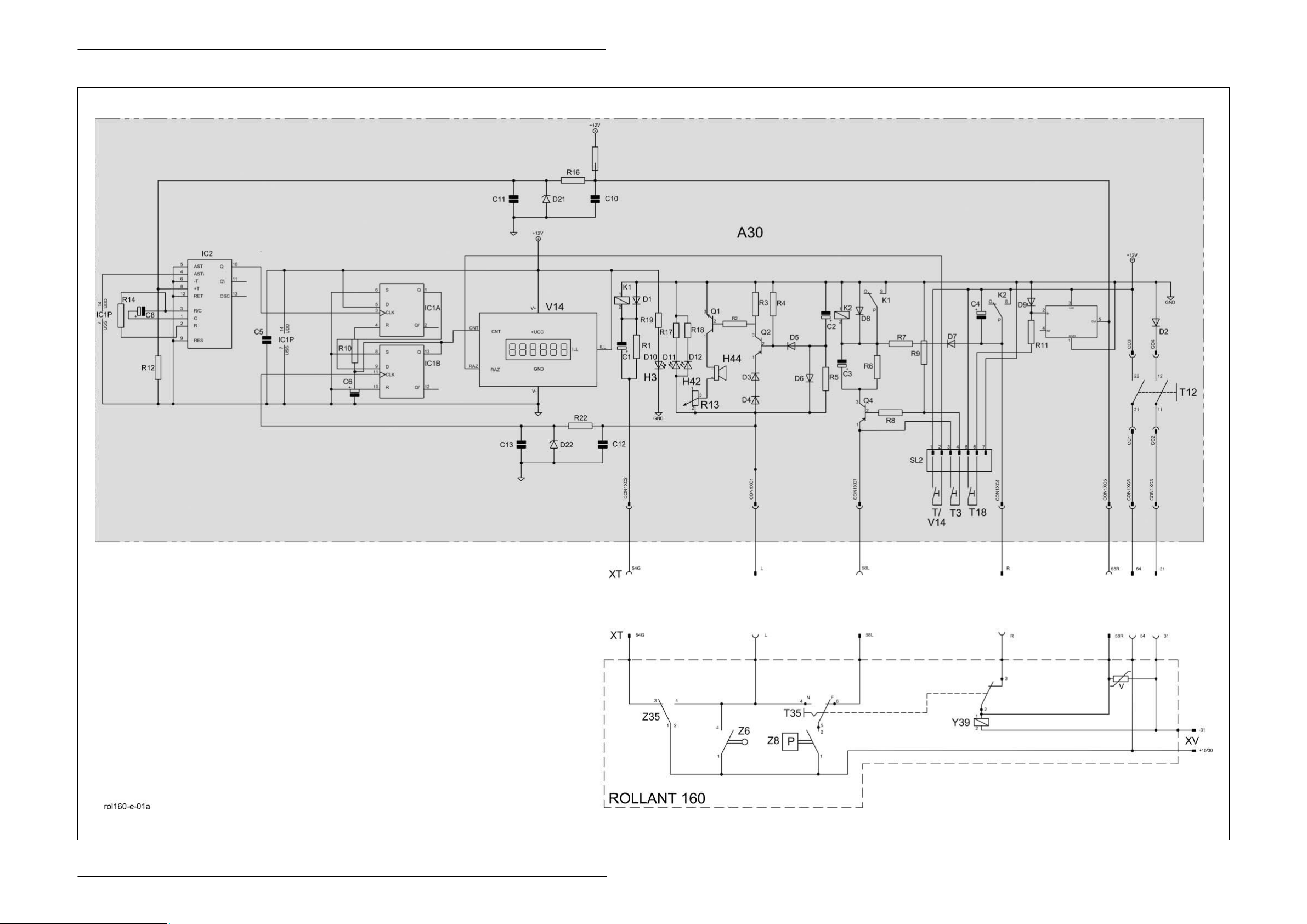
1.1 Electric system overall circuit diagram
1-4 RO-160 03/04

TIC Rollant 160 Technical Systems
Key to diagram:
A30 Terminal
Con1 Wiring loom XT connection
H3 Operation signal light
H42 STOP signal light
H44 Buzzer
K1 Switching relay
K2 Switching relay
R13 Potentiometer / Volume (Buzzer)
SL2 Operating controls connection
T3 Delayed wrapping switch
T12 Main switch
T18 Manual wrapping start switch
T35 Wrapping type pre-selection switch
T V14 Reset bale counter switch
V Varistor (Delete induction voltage)
V14 Bale counter
XT Terminal connector
XV 12 Volt power supply
Y39 Twine/net coupling solenoid coil
Z6 Bale ejector switch
Z8 Wrapping start oil pressure switch (Baling pressure reached)
Z35 Cam track switch
03/04 RO-160 1-5
 Loading...