

Page 1

QUANTUM 6800
P
QUANTUM 3500 - 6800
Technical Systems
Page 2

Technical Systems QUANTUM TIC
10/04
Page 3

TIC QUANTUM Technical Systems
Chapters
1 Technical Data
3 Operation
10 Brakes
11 Hydraulic System
12 Electric System / Diagnosis
10/04
Page 4

Technical Systems QUANTUM TIC
10/04
Page 5

TIC QUANTUM Technical Data
1.0 QUANTUM 2500 K, 2500 P, 3500 K, 3500 P, 3800 K, 3800 P..............................................................2
1.1
QUANTUM 3500 K, 3500 P, 3500 S, 3800 K, 3800 P, 2500 K, 2500 P..............................................2
1.2 QUANTUM 5500 S-18, 5500 S-16, 5500 S, 4500 S, 6800 S ..............................................................5
1.3 QUANTUM 6800 P, 6500 P, 5500 P-18, 5500 GT, 5500 P, 4500 P ...................................................8
10/04 1-1
Page 6
Technical Data QUANTUM TIC
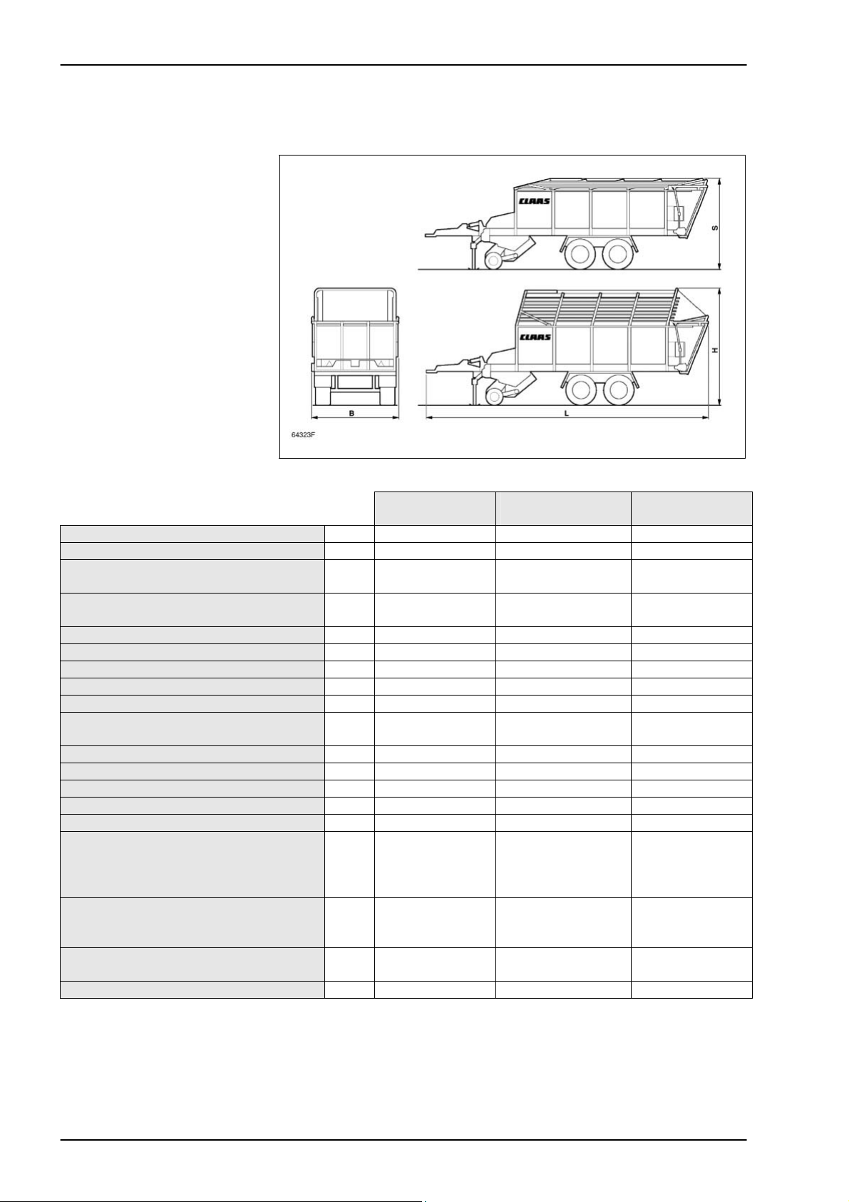
1.0 QUANTUM 2500 K, 2500 P, 3500 K, 3500 P, 3800 K, 3800 P
1.1 QUANTUM 3500 K, 3500 P, 3500 S, 3800 K, 3800 P, 2500 K, 2500 P
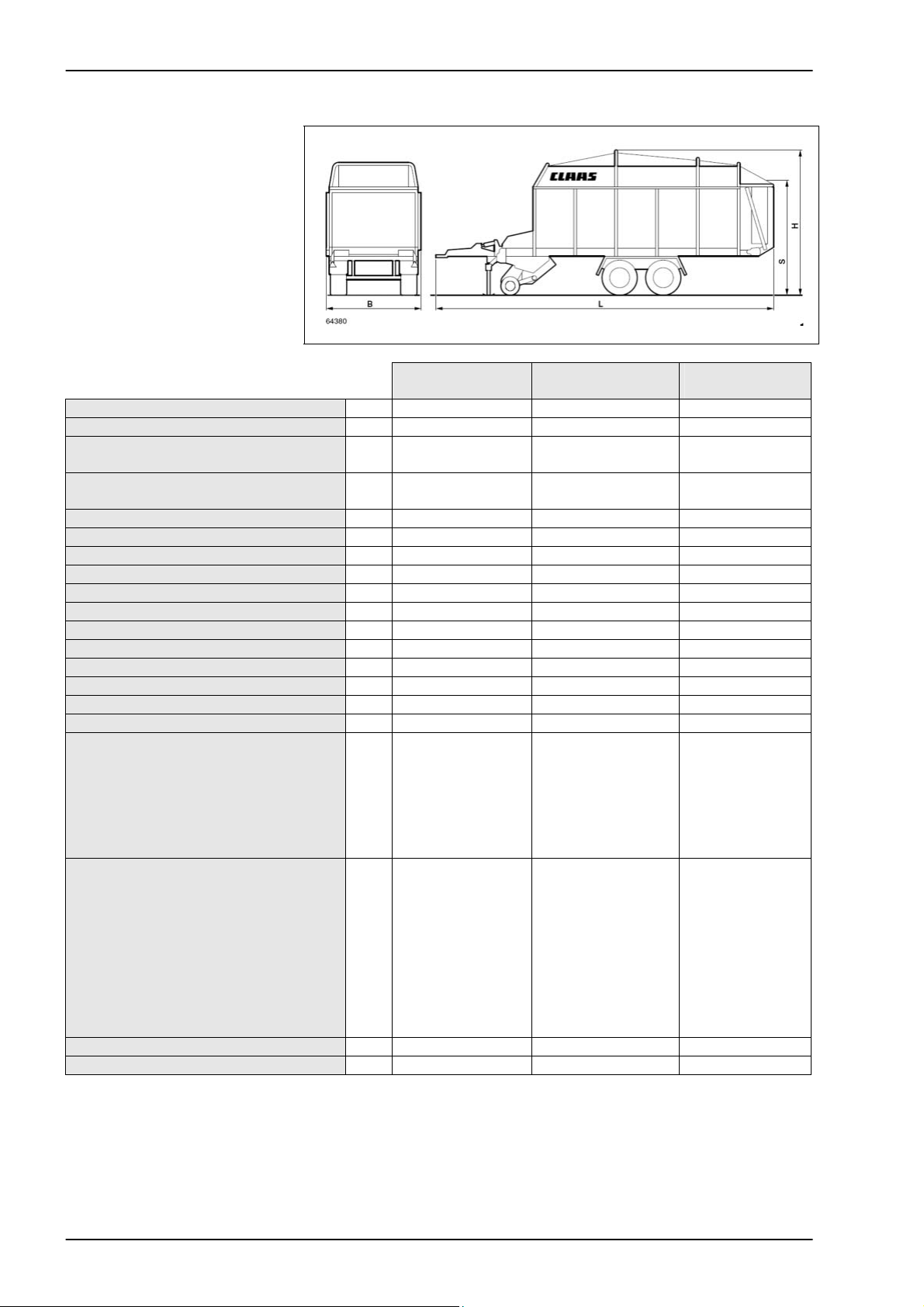
Length (L) mm 8,100 8,100 8,200
Width (B) mm 2,550 2,550 2,550
Height (H) – dry forage assembly folded
up
Height (S) – dry forage assembly folded
down
Track width mm 1,850 1,850 1,850
Pick-up width mm 1,800 1,800 1,800
Platform height mm 1,180 1,180 1,180
Loading capacity (acc. to DIN 11741) m3 26.6 28 25.6
Kerb weight kg 5,160 5,200 5,860
Permissible total weight (Rückmatic /
compressed air)
Number of cutting knives 33 33 33
Shortest theoretical length of cut mm 45 45 45
Number of pick-up tines per tine bar 26 26 26
Tine spacing mm 61 61 61
PTO speed min-1 1,000 1,000 1,000
Tyres - Rückmatic up to 40 km/h
or
- compressed air up to 40 km/h
- compressed air up to 60 km/h
Tyre pressure - with tyres 500/50-17
555/45-17
19.0/45-17
Tightening torque of wheel nuts - wagon
wheels
Sound pressure level dB(A) 70 70 70
QUANTUM
3500 K
QUANTUM
3500 P
QUANTUM
3500 S
mm 3,410 3,600 3,600
mm 2,600 3,050 3,050
8,000/11,000 8,000/11,000 8,000/11,000
19.0/45-17
500/50-17 10 PR
555/45-17 10 PR
500/50-17 10 PR
bar
bar
bar
3.5
3.0
3.0
19.0/45-17
500/50-17 10 PR
500/50-17 10 PR
500/50-17 10 PR
3.5
3.0
3.0
19.0/45-17
500/50-17 10 PR
555/45-17 10 PR
555/45-17 10 PR
3.5
3.0
3.0
Nm 300 300 300
1-2 10/04
Page 7

TIC QUANTUM Technical Data
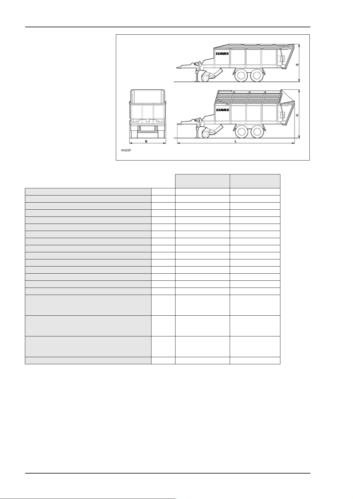
QUANTUM
2500 K
QUANTUM
2500 P
Length (L) mm 8,100 8,100
Width (B) mm 2,550 2,550
Height (H) – dry forage assembly folded up mm 3,410 3,600
Height (S) – dry forage assembly folded down mm 2,600 3,050
Track width mm 1,850 1,850
Pick-up width mm 1,800 1,800
Platform height mm 1,180 1,180
Loading capacity (acc. to DIN 11741) m3 26.6 28
Kerb weight kg 4,500 4,750
Permissible total weight
8,000/11,000 8,000/11,000
(Rückmatic / compressed air)
Number of cutting knives 33 33
Shortest theoretical length of cut mm 40 40
Number of pick-up tines per tine bar 26
Tine spacing mm 61 61
PTO speed min-1 540 540
Tyres - Rückmatic up to 40 km/h
or
- compressed air up to 40 km/h
- compressed air up to 60 km/h
Tyre pressure - with tyres 500/50-17
555/45-17
9.0/45-17
15.0/55-17
Tightening torque of wheel nuts - wagon
wheels M18x1.5
M20x1.5
Sound pressure level dB(A) 70 70
15.0/55-17
19.0/45-17
500/50-17 10 PR
500/50-17 10 PR
555/45-17 10 PR
bar
bar
bar
bar
Nm
Nm
3.5
3.0
3.0
3.5
270
380
15.0/55-17
19.0/45-17
500/50-17 10 PR
500/50-17 10 PR
555/45-17 10 PR
3.5
3.0
3.0
3.5
270
380
10/04 1-3
Page 8
Technical Data QUANTUM TIC
QUANTUM
3800 K
QUANTUM
3800 P
Length (L) mm 9,250 9,250
Width (B) mm 2,550 2,550
Height (H) – dry forage assembly folded up mm 3,410 3,600
Height (S) – dry forage assembly folded down mm 2,600 3,050
Track width mm 1,850 1,850
Pick-up width mm 1,800 1,800
Platform height mm 1,180 1,180
Loading capacity (acc. to DIN 11741) m3 31.8 33.2
Kerb weight kg 5,550 5,650
Permissible total weight (compressed air) 11,000 11,000
Number of cutting knives 33 33
Shortest theoretical length of cut mm 45 45
Number of pick-up tines per tine bar 26 26
Tine spacing mm 61 61
PTO speed min-1 1.000 1.000
Tyres
- compressed air up to 40 km/h
- compressed air up to 60 km/h
Tyre pressure - with tyres 500/50-17
555/45-17
19.0/45-17
Tightening torque of wheel nuts - wagon
wheels M18x1.5
M20x1.5
Sound pressure level dB(A) 70 70
500/50-17 10 PR
555/45-17 10 PR
bar
bar
bar
3.5
3.0
3.0
500/50-17 10 PR
555/45-17 10 PR
Nm
270
300
3.5
3.0
3.0
270
300
1-4 10/04
Page 9

TIC QUANTUM Technical Data
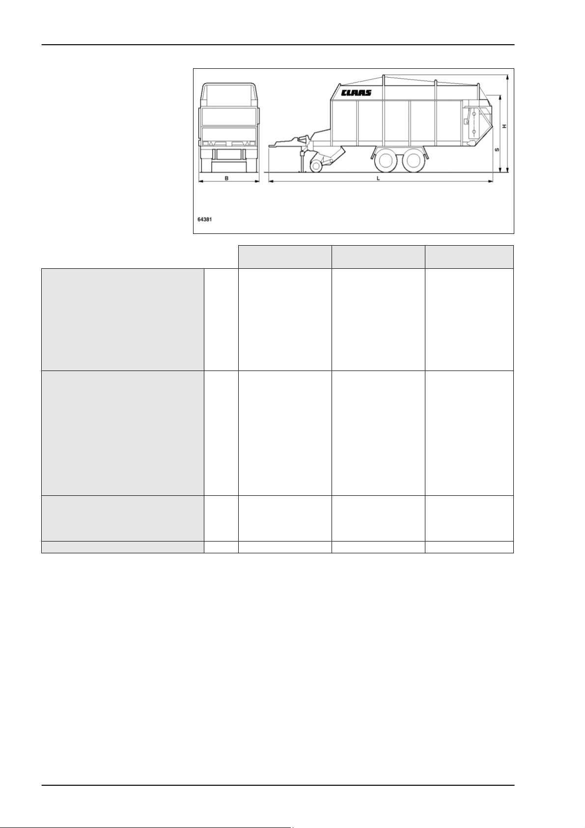
1.2 QUANTUM 5500 S-18, 5500 S-16, 5500 S, 4500 S, 6800 S
QUANTUM
5500 S-18
QUANTUM
5500 S-16
QUANTUM
6800 S
Length (L) mm 9,250 9,250 10,500
Width (B)
- Standard
- with tyres 700/45-22.5
- with tyres 600/55-R26.5
- with tyres 700/50-R26.5
- with tyres 800/40-R26.5
Height (H) - dry forage assembly folded
up
mm
2,550
2,720
-
-
mm
mm
3,990
-
2,550
-
-
-
-
3,930
-
2,550
2,720
2,550
2,750
2,930
3,990
4,000
- with tyres 800/40-R26.5
Height (S) - dry forage assembly folded
up
mm
mm
3,290
-
3,230
-
3,290
3,300
- with tyres 800/40-R26.5
Track width - with tyres 22.5
- with tyres 26.5
mm
mm
1,950
-
1,950
-
1,950
2,000
Pick-up width mm 1,800 1,800 1,800
Platform area mm 2,160 x 5,700 2,160 x 5,700 2,160 x 5,700
Loading capacity (acc. to DIN 11741) m3 31 31 38
Kerb weight
with tyres 800/40-R26.5
incl. forced steering
kg
kg
8,340
-
7,600
-
8,810
9,350
Permissible total weight 18,000 16,000 20,000
Number of cutting knives 33 33 33
Shortest theoretical length of cut mm 45 45 45
Number of pick-up tines per tine bar 26 26 26
Tine spacing mm 61 61 61
PTO speed min-1 1,000 1,000 1,000
10/04 1-5
Page 10
Technical Data QUANTUM TIC
Tyres:
- up to 40 km/h without AGS
- up to 50 km/h without AGS
- up to 60 km/h without AGS
- up to 60 km/h air suspension
- Pick-up wheels
Tyre pressure
- with tyres: 555/45-17
500/55-20
600/55-22.5
550/45-R22.5
650/50-R22.5
700/45-22.5
600/55-R26.5
700/50-R26.5
800/40-R26.5
Pick-up wheels
Tightening torque of wheel nuts
M18 x x1.5
M20 x 1.5
M22 x x1.5
Sound pressure level dB(A) 70 70 70
QUANTUM
5500 S-18
700/45-22.5 12PR
-
-
600/55-22.5 12PR
650/50-R22.5 12PR
-
-
16x6.5-8 4PR
bar
-
-
3.0
-
3.0
1.5
-
-
-
2.5
Nm
380
510
QUANTUM
5500 S-16
555/45-17 154F
-
-
550/45-R22.5
555/45-17 154F
-
500/55-20 12PR
16x6.5-8 4PR
3.0
4.5
-
3.0
-
-
-
-
-
2.5
270
-
-
QUANTUM
6800 S
700/45-22.5 12PR
700/50-R26.5
800/40-R26.5
-
650/50-R22.5 12PR
600/55-R26.5
-
16x6.5-8 4PR
-
-
3.0
-
3.0
1.5
3.0
1.5
1.5
2.5
-
-
510
1-6 10/04
Page 11
TIC QUANTUM Technical Data
QUANTUM
5500 S
QUANTUM
4500 S
Length (L) mm 9,250 8,160
Width (B) mm 2,550 2,550
Height (H)
– dry forage assembly folded up
– dry forage assembly folded down
mm
mm
3,840
3,040
3,840
3,040
Track width mm 1,850 1,850
Pick-up width mm 1,800 1,800
Platform height mm 1,240 1,240
Platform area mm 2,160 x 5,700 2,160 x 4,700
Loading capacity (acc. to DIN 11741) m3 31 26,3
Kerb weight kg 6,920 6,500
Permissible total weight 13,000 11,000
Number of cutting knives 33 33
Shortest theoretical length of cut mm 45 45
Number of pick-up tines per tine bar 26 26
Tine spacing mm 61 61
PTO speed min-1 1,000 1,000
Tyres - up to 40 km/h without AGS
- up to 60 km/h without AGS
- up to 80 km/h with AGS
- up to 60 km/h air suspension
- Pick-up wheels
Tyre pressure - with tyres 500/50-17
555/45-17
500/55-20
16x6.5-8
Tightening torque of wheel nuts – wagon
555/45-17 146F
555/45-17 146F
555/45-17 146F
555/45-17 146F
16x6.5-8 4PR
bar
bar
bar
-
3.0
-
2.5
500/50-17 10PR
555/45-17 146F
555/45-17 146F
-
16x6.5-8 4PR
3.5
3.0
-
2.5
Nm 300 300
wheels
Sound pressure level dB(A) 70 70
10/04 1-7
Page 12
Technical Data QUANTUM TIC
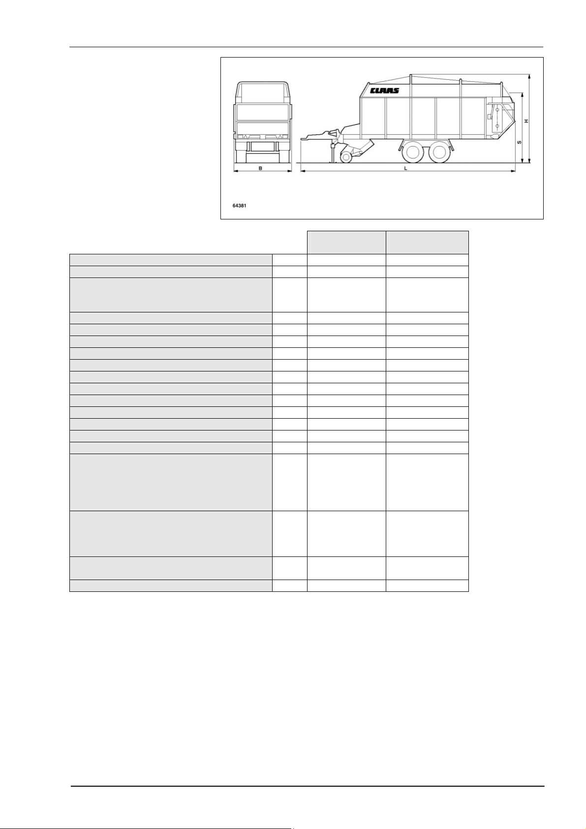
1.3 QUANTUM 6800 P, 6500 P, 5500 P-18, 5500 GT, 5500 P, 4500 P
QUANTUM
6800 P
QUANTUM
6500 P
QUANTUM
5500 P-18
Length (L) mm 10,180 10,019 9,250
Width (B) mm 2,550 2,550 2,550
Height (H) – dry forage assembly
mm 3,990 3,950 3,990
folded up
Height (S) – dry forage assembly
mm 3,290 3,190 3,290
folded down
Track width mm 1,950 1,950 1,950
Pick-up width mm 1,800 1,800 1,800
Platform height mm 1,240 1,240 1,490
Platform area mm 2,160 x 7,600 2,160 x 7,550 2,160 x 6,550
Loading capacity (acc. to DIN 11741) m3 40 45.7 34
Kerb weight kg 8,030 7,440 7,240
Permissible total weight kg 20,000 16,000 18,000
Number of cutting knives 33 33 33
Shortest theoretical length of cut mm 45 45 45
Number of pick-up tines per tine bar 26 26 26
Tine spacing mm 61 61 61
PTO speed min
Tyres - up to 40 km/h without AGS
- up to 50 km/h without AGS
- up to 60 km/h without AGS
- up to 80 km/h with AGS
- up to 60 km/h air suspension
- Pick-up wheels
Tyre pressure - with tyres
555/45-17
500/55-20
600/55-22.5
650/50-R22.5
700/45-22.5
600/55-R26.5
700/50-R26.5
800/40-R26.5
Pick-up wheels
-1
1,000 1,000 1,000
700/45-22.5 12PR
700/50-R26.5
-
650/50-22.5 12PR
-
-
16x6.5-8 4PR
bar
-
-
3.0
3.0
1.5
3.0
1.5
1.5
2.5
2x 500/50-17 14PR
4x 8.25 R70 14PR
-
-
-
-
16x6.5-8 4PR
4.5
4.5
-
-
-
-
2.5
-
600/55-22.5 12PR
650/55-22.5 12PR
-
-
16x6.5-8 4PR
-
-
3.0
3.0
1.5
-
-
-
2.5
Tightening torque of wheel nuts Nm 300 300 300
Sound pressure level dB(A) 70 70 70
1-8 10/04
Page 13

TIC QUANTUM Technical Data
QUANTUM
5500 GT
QUANTUM
5500 P
QUANTUM
4500 P
Length (L) mm 8,860 8,860 7,770
Width (B) mm 2,550 2,550 2,550
Height (H) – dry forage assembly folded up mm 3,800 3,800 3,800
Height (S) – dry forage assembly folded
mm 3,040 3,040 3,040
down
Track width mm 1,900 1,850 1,850
Pick-up width mm 1,800 1,800 1,800
Platform height mm 1,240 1,240 1,240
Platform area mm 2,160 x 6,500 2,160 x 6,550 2,160 x 5,400
Loading capacity (acc. to DIN 11741) m3 34 34 29.3
Kerb weight kg 6,550 6,200 5,740
Permissible total weight kg 16,000 13,000 11,000
Number of cutting knives 33 33 33
Shortest theoretical length of cut mm 45 45 45
Number of pick-up tines per tine bar 26 26 26
Tine spacing mm 61 61 61
PTO speed min-1 1,000 1,000 1,000
Tyres - up to 40 km/h without AGS
- up to 50 km/h without AGS
- up to 60 km/h without AGS
- up to 60 km/h air suspension
- Pick-up wheels
Tyre pressure
- with tyres 500/50-17
550/45-R22.5
555/45-17
500/55-20
550/45-17 154F
Pick-up wheels
Tightening torque of wheel nuts
M18 x 1.5
M20 x 1.5
Sound pressure level dB(A) 70 70 70
555/45-17 154F
550/45-R22.5
555/45-17 145F
500/55-20 12PR
16x6.5-8 4PR
bar
-
-
4.5
3.5
3.0
2.5
Nm
270
380
555/45-17 146F
-
555/45-17 146F
16x6.5-8 4PR
-
-
3.0
3.0
-
2.5
270
380
500/50-17 10PR
-
555/45-17 146F
-
16x6.5-8 4PR
3.5
3.0
3.0
-
-
2.5
270
380
10/04 1-9
Page 14

Technical Data QUANTUM TIC
1-10 10/04
Page 15

TIC QUANTUM Operation
1.0 QUANTUM 2500 K, 2500 P, 3500 K, 3800 K, 3800 P, 3500 S ..........................................................2
1.1 Control box short instructions .....................................................................................................3
1.2 Operation ....................................................................................................................................4
2.0 QUANTUM 4500 S / 5500 S / S-16 / S-18 / 6800 S ............................................................................8
2.1 Control box short instructions .....................................................................................................9
2.2 Operation ..................................................................................................................................11
3.0 QUANTUM 4500 P / 5500 P / 5500 P-16 / 5500 P-18 / 5500 GT / 6800 P.......................................18
3.1 Control box short instructions ...................................................................................................19
3.2 Operation ..................................................................................................................................21
10/04 3-1
Page 16
Operation QUANTUM TIC
1.0 QUANTUM 2500 K, 2500 P, 3500 K, 3800 K, 3800 P, 3500 S
Caution! When draining oil over a more extended period than usual (tractor –
forage wagon – floor conveyor), the pump system of the tractor must be
known (see “Prior to operation – Hydraulic system”).
The buttons on the control box are only used to pre-select the different
functions of the forage wagon. Operating the single-acting control valve
on the tractor will activate the desired function.
Between the different operations, the single-acting control valve of the
tractor must be switched back to the neutral position.
Only then a new function can be pre-selected on the control box.
The floor conveyor is controlled using the double-acting control valve on
the tractor.
On the S-wagon, the floor conveyor speed can be varied using the rotary
knob. This knob has no function on the K and P wagons!
3-2 10/04
Page 17

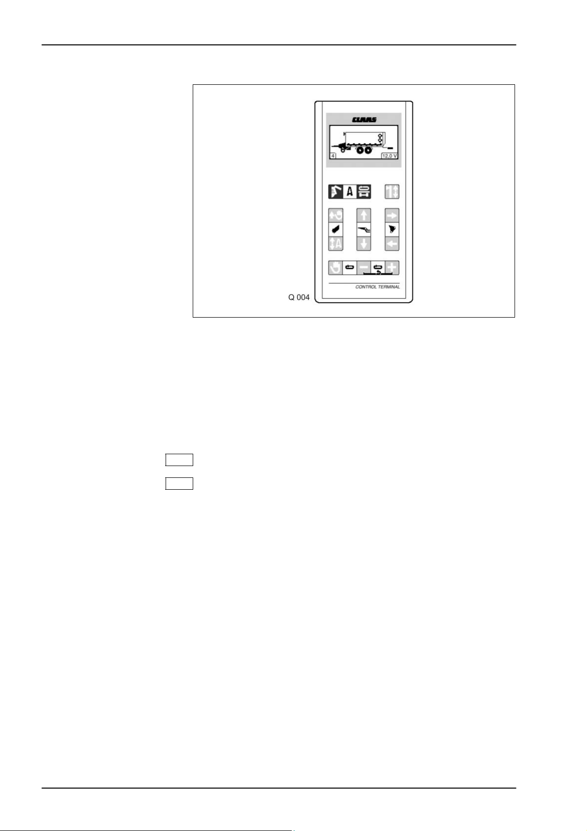
TIC QUANTUM Operation
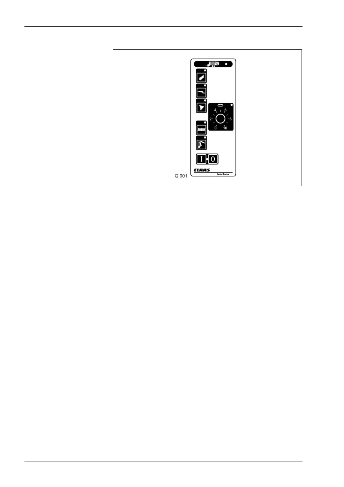
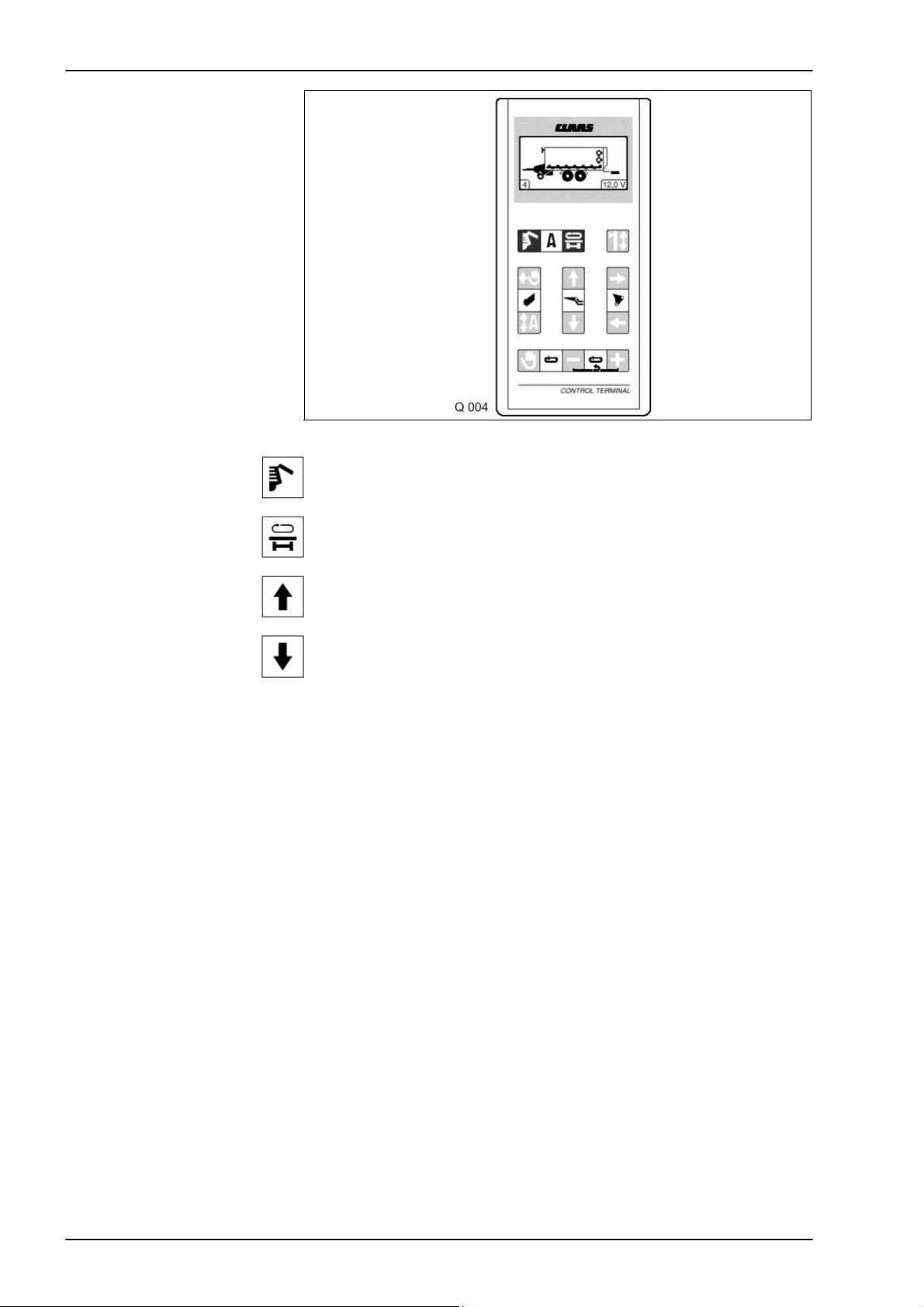
1.1 Control box short instructions
Loading operation
Knife frame
Control system ON
Control system OFF
Pick-up up/down
Dry crop top up/down
(Quantum 3500 K only)
Wagon full indicator
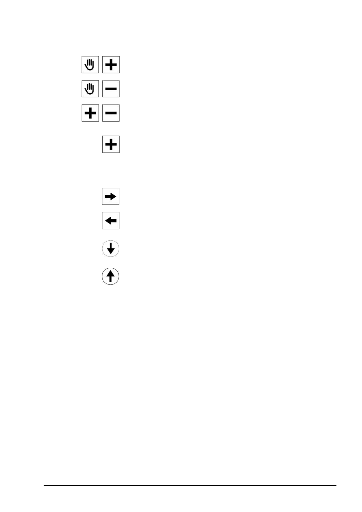
Opens / closes the cutting trough
Opens the cutting trough totally
Unloading operation
Articulated drawbar
Opens / closes the tailgate
Drawbar up/down
10/04 3-3
Page 18
Operation QUANTUM TIC
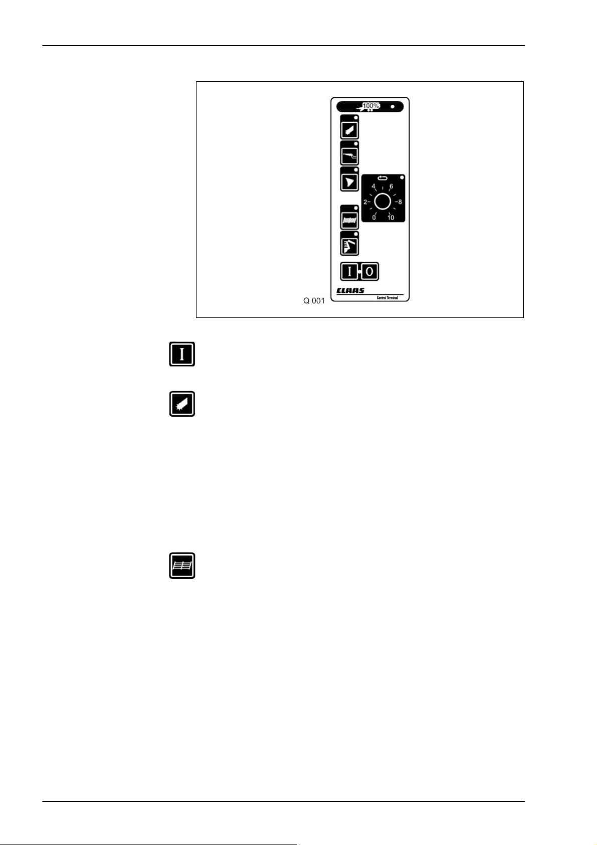
1.2 Operation
Loading operation
Pick-up
lowered/raised
Use this key of the control box to switch on the control unit. The red
indicator light lights up.
Use this key to pre-select the pick-up mode. The pick-up can now be
raised and lowered using the single-acting control valve. Switch
on the pto for loading.
Attention The pick-up will only remain in floating position if the pick-up mode is pre-
selected on the control box and the single-acting control valve is set to
floating position.
Quantum 3500 K / 3800 K /
To switch off the rotor and the pick-up the pto must be disengaged.
3500 P / 3800 P
Quantum 3500 S Raising the pick-up will automatically disengage the rotor and the pick-up.
Dry crop top
(QUANTUM 2500 K,
3500 K only)
Use this key to pre-select the dry crop top mode. To erect the dry
crop top, pressurize the single-acting control valve. To lower it, set
the system to the float position.
3-4 10/04
Page 19
TIC QUANTUM Operation
Floor conveyor
Floor conveyor speed
Opening the knife frame
The floor conveyor is controlled using the double-acting control valve on
the tractor. To set the floor conveyor to forwards or reverse, set the
double-acting control valve to the raise or lower position.
QUANTUM 3500 S:
The floor conveyor speed can be varied using the rotary knob provided
the pick-up or the tailgate has been pre-selected.
QUANTUM 3500 K / P, 2500 K / P, 3800 K / P:
If the tractor is fitted with a flow rate controller, this can be used to vary
the floor conveyor speed.
The knob on the control unit has no function on the K and P
wagons.
If a blockage occurs in the conveyor channel (cut-out clutch of the
universal drive shaft is activated), switch off the pto.
Use this key to select the cutting mechanism mode. Set the lever
on the single-acting control valve to the float position in order to
open the knife frame.
Engage the pto to clear the blockage. Once the channel is free, close the
knife frame again by moving the lever on the single-acting control valve
to the pressure setting.
If the knife frame has to be totally lowered (e.g. for repair work or for
the replacement of knives), first set the single-acting valve to the
float position and then press these two buttons simultaneously.
Attention If the knife frame is totally open, it must be closed very carefully and
“Wagon full” indicator
To close the knife frame, set the control unit to the pressure setting.
slowly. When folding up the frame, ensure that the cutting knives will not
collide with the rotor tines.
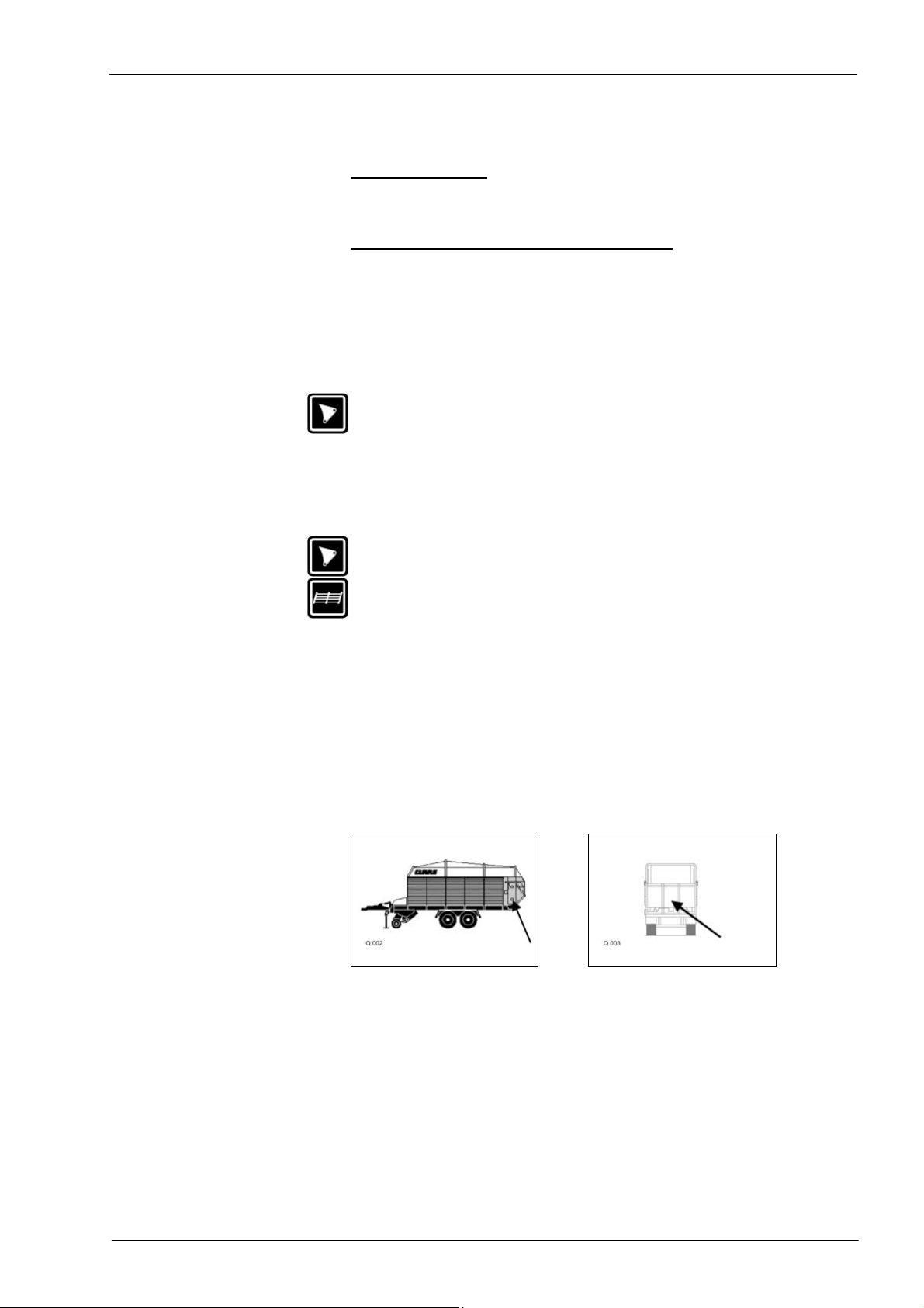
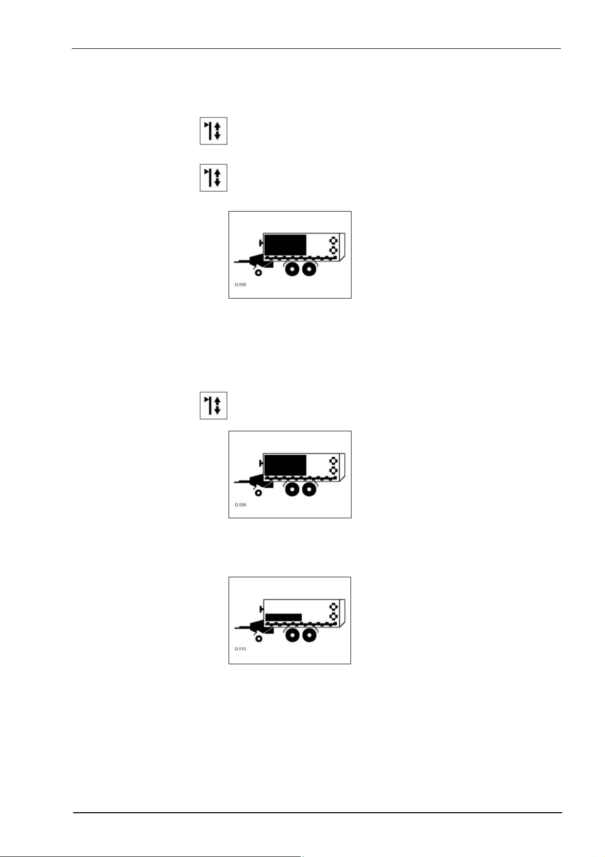
The load space is filled when the “wagon full” indicator of the display
flashes (see figure). Switch off the floor conveyor, raise the pick-up and
switch off the universal drive shaft.
QUANTUM 3500 S QUANTUM 3500 P / K
2500 P / K
3800 P / K
10/04 3-5
Page 20

Operation QUANTUM TIC
Unloading operation
Silo operation
Discharging the load
QUANTUM 3500 S
Attention If the swash plates are folded down, opening the tailgate is not allowed.
Discharging the load
QUANTUM
2500 K / P
3500 K / P
3800 K / P
Use this key of the control box to switch on the control unit. The
indicator light lights up.
For silo operation raise the wagon at the front with the articulated
drawbar. Use this key for pre-selecting the articulated drawbar and
set the single-acting control valve to the pressure setting. When
unloading is complete, lower the wagon again. Set the control unit
to the float position.
Open the tailgate before unloading. Use this key for pre-selecting
the tailgate and set the single-acting control valve to the pressure
setting.
Open the tailgate to enable activation of the shredder drums via the pto.
Then initiate the floor conveyor using the double-acting control valve. The
floor conveyor speed can be varied using the rotary knob. To close the
tailgate, the set the single-acting control valve to the float position until
the tailgate has closed completely.
Open the tailgate before unloading. Use this key for pre-selecting
the tailgate and set the single-acting control valve to the pressure
setting.
Initiate the floor conveyor using the double-acting control valve. To
close the tailgate, the set the single-acting control valve to the float
position until the lock has engaged.
To reverse the floor conveyor, move the lever of the double-acting
control valve to the opposite direction. If the tractor is fitted with a flow
rate controller, this can be used to vary the floor conveyor speed.
3-6 10/04
Page 21

TIC QUANTUM Operation
10/04 3-7
Page 22
Operation QUANTUM TIC
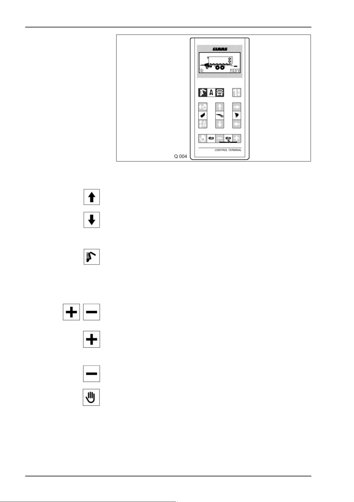
2.0 QUANTUM 4500 S / 5500 S / S-16 / S-18 / 6800 S
Control light (rear wheel)
flashes when steering axle
is locked (reverse travel)
Caution: 1. Electric System
Connect the 2-pole plug with the tractor = on-board voltage to
the distributor box.
2. To switch on the control box, the hydraulic system must be
pressurized = (2 bar switch) on-board voltage from the distributor
box to the control box.
The pump system of the tractor must be known (see chapter “Before
operating the hydraulic system”).
12 V On-board voltage display (10.8 V min., 15.5 V max.)
4 Display of floor conveyor speed
3. Flashing wheel
The axle’s straight position is blocked by means of the cross
conveyor key and a 3/2 way valve = flashing wheel.
QUANTUM with a separate hydraulic connection (single-acting) do not
have this equipment.
3-8 10/04
Page 23

TIC QUANTUM Operation
2.1 Control box short instructions
Loading operation/
manual
Pick-up up/down
The pick-up disengages when raised.
Setting filling mode/
automatic filling ON/OFF
Raise the pick-up.
The pick-up does not disengage when raised,
benefit: this is easier on the dog clutch.
Pick-up down
Floor conveyor ON/
save floor conveyor speed
Floor conveyor speed
Speed down
Speed up
(Option S = quick unloading via 2-speed motor)
Reverse conveyor floor
Cutting mechanism
Open knife frame 1
st
position
Close knife frame 1
st
position
Open knife frame 2
nd
position
Close knife frame 2
nd
position
10/04 3-9
Page 24
Operation QUANTUM TIC
Unloading operation
Articulated drawbar
Unloading operation start/stop
Turning direction of cross conveyor belt and locking/unlocking of
steering axle.
Articulated drawbar up
Articulated drawbar down
3-10 10/04
Page 25

TIC QUANTUM Operation
2.2 Operation
Loading operation
Pick-up
up/down
Manually changing the
pick-up working width
To switch on the control unit, set the hydraulic system to the pressure
setting. The display shows the forage wagon. Switch on the pto shaft.
This button is used for lowering the pick-up to the float position.
The wagon is automatically loaded. Pressing this button again raises
the pick-up and the loading process is stopped. With the pto
switched on, the pick-up drive and the rotor are automatically
switched off when raising the pick-up. They are restarted when
lowering the pick-up.
In difficult ground and crop conditions, the pick-up can be raised
during loading by means of this button. The pick-up is no longer in
the float position.
The pick-up is lowered again using this button.
Adjusting the load space
filling
(up to serial no.)
Attention:
From serial no. … there are no reed switches available for half-loading
the front panel. However, the wiring loom remains unchanged = the plugs
for the reed switches are available. The switching options include only
“Full loading” and “Manual loading”.
This button can be used to vary the loading mode.
Its functions depends on the position of micro switch (3) located in
the front part of the control box (4).
Micro switch (3) in lower position (OFF / standard setting):
This button on the control box enables switching back and forth
between full and half loading.
3 Micro switch 4 Control box
For micro switch position see
chapter 13 “Electric System”.
10/04 3-11
Page 26

Operation QUANTUM TIC
The black filling bar ceases
to apply from serial no. and
installation of EPROM
350 812-5.
Upper position
(e.g. for loading dry fodder): The floor conveyor is switched on when the
cover plates are raised. All 3 plates are linked with one another.
The black filling bar ceases
to apply from serial no. and
installation of EPROM
350 812-5.
Lower position
(e.g. for loading green fodder and silage): The floor conveyor is switched
on when the feelers at the front wall are lifted.
The floor conveyor will run until the feelers and/or the top plate are free
again.
Micro switch (3) in top
position:
Using this button allows switching between fully loading the wagon
and deactivating the automatic filling.
The black filling bar ceases
to apply from serial no. and
installation of EPROM
350 812-5.
Upper position
(e.g. for loading dry fodder): The floor conveyor is switched on when the
centre top plate is raised.
The black filling bar ceases
to apply from serial no. and
installation of EPROM
350 812-5.
The filling indicator disappears:
The automatic filling mode is deactivated; the floor conveyor has to be
operated manually.
To adjust the micro switch, switch off the control box and the oil supply
from the tractor. Then open the distributor box located in the front part of
the wagon and switch over using a small screwdriver. Close the box and
connect the oil supply to the tractor.
3-12 10/04
Page 27
TIC QUANTUM Operation
Adjusting the load space
filling
(from serial no.)
Attention:
From serial no. … there are no reed switches available for half-loading
the front panel. However, the wiring loom remains unchanged = the plugs
for the reed switches are available.
This button can be used to vary the loading mode. Its functions
depends on the position of micro switch (3) located in the front part
of the control box (4).
Micro switch (3) in lower
position (OFF / standard
setting):
Using this button allows switching back and forth between fully
loading the wagon and manual loading (under visual control).
The black filling bar ceases
to apply from serial no. and
installation of EPROM
350 812-5.
Upper position
(e.g. for loading dry fodder): The floor conveyor is switched on when the
cover plates are raised. All 3 plates are linked with one another.
The floor conveyor will run until the feelers and/or the top plate are free
again or the manual actuation is shut down..
Micro switch (3) in top
position:
Using this button allows switching between fully loading the wagon
and deactivating the automatic filling.
The black filling bar ceases
to apply from serial no. and
installation of EPROM
350 812-5.
Upper position
(e.g. for loading dry fodder): The floor conveyor is switched on when the
cover plates are raised. All 3 plates are linked with one another.
The black filling bar ceases
to apply from serial no. and
installation of EPROM
350 812-5.
The filling indicator disappears:
The automatic filling mode is deactivated; the floor conveyor has to be
operated manually.
To adjust the micro switch, switch off the control box and the oil supply
from the tractor. Then open the distributor box located in the front part of
the wagon and switch over using a small screwdriver. Close the box and
connect the oil supply to the tractor.
10/04 3-13
Page 28

Operation QUANTUM TIC
The black filling bar ceases
to apply from serial no. and
installation of EPROM
350 812-5.
Floor conveyor
End of loading operation
When the crop presses against the lower shredder drum, it is moved
backwards slightly. The switch (6) closes and the floor conveyor is
automatically switched off. The filling indicator on the display is flashing.
Raise the pick-up and switch off the universal drive shaft.
Manual operation of floor
conveyor
If the automatic filling mode is not used or the load space is only to
be partially filled, the floor conveyor can be operated manually using
this key. Here the floor conveyor speed is always as previously set.
3-14 10/04
Page 29
TIC QUANTUM Operation
Adjusting the floor conveyor
speed
Pressing this button increases the floor conveyor speed of all further
runs.
Pressing this button decreases the floor conveyor speed of all further
runs.
The floor conveyor can also be reversed during loading by
simultaneously pressing both buttons. Reversing is always carried out at
speed 9.
After the floor conveyor has been reversed, the floor conveyor speed
must be increased by pressing this button.
Open / close knife frame
The floor conveyor speed is displayed at the bottom left in the control
panel display. It can be adjusted within the range from 0 to 9: 0 – 9
(standstill – fast)
Open the cutting frame by means of this button (1
pto to clear the blockage.
As soon as the conveyor channel is free, close the cutting frame by
pressing this key. Press this key until the display shows a totally closed
knife frame.
If the knife frame is to be completely lowered (2
dismounting the rotor), this key must be pressed above the cutting
trough.
Close the knife frame by pressing this key above the knife frame.
st
stage). Engage the
nd
stage, e.g. for repairs or
Attention!
If the knife frame is totally open, it must be closed very carefully and
slowly.
When folding up the frame, ensure that the cutting knives will not collide
with the rotor tines.
10/04 3-15
Page 30
Operation QUANTUM TIC
The black filling bar ceases
to apply from serial no. and
installation of EPROM
350 812-5.
Unloading in silo
operation
To switch on the control unit, set the hydraulic system to the pressure
setting. The display shows the forage wagon.
Press this button to raise the wagon over the articulated drawbar at the
front.
When unloading is complete, use this key to lower the wagon again. The
floor conveyor switches to the 4
Discharge of the load
space
Switch on the pto shaft. Press this button for unloading. The tailgate
opens, the shredder drums start running and the floor conveyor is
switched on after a short delay. To stop the unloading process, press this
button again.
Any blockage of the shredder drums (the cut-out clutch of the universal
drive shaft is activated) by the material requires reversing the floor
conveyor.
Press these buttons simultaneously to reversing the floor conveyor. After
the floor conveyor has been reversed, the floor conveyor speed must be
increased by pressing the + button.
Pressing this button increases the floor conveyor speed. By increasing
the speed numbers up to speed 9 and pressing this key once again, an
“S” appears in the control panel display = quick conveyor speed due to 2speed hydraulic motor.
Pressing this button decreases the floor conveyor speed.
th
stage.
When pressing this key during the whole unloading process, the adjusted
floor conveyor speed is saved for further unloading processes.
3-16 10/04
Page 31

TIC QUANTUM Operation
Unloading by means of
cross conveyor belt
Pull out the cross conveyor belt before unloading and lock it to the lower
back cover. Connect the hydraulic hoses to the hydraulic motor.
Switch on the pto for unloading with the cross conveyor belt and press
this key. The shredder drums start running and the floor conveyor is
switched on after a short delay.
To stop the unloading process, press this button again.
Any blockage of the shredder drums (the cut-out clutch of the universal
drive shaft is activated) by the material requires reversing the floor
conveyor.
Press these buttons simultaneously to reversing the floor conveyor.
Pressing this button increases the floor conveyor speed.
Pressing this button decreases the floor conveyor speed.
When pressing this key during the whole unloading process, the adjusted
floor conveyor speed is saved for further unloading processes.
This key enables changing the direction of rotation of the cross conveyor
belt.
From serial no.: …. with solenoid valve 62, the trailing axle can be
blocked with this key.
10/04 3-17
Page 32

Operation QUANTUM TIC
3.0 QUANTUM 4500 P / 5500 P / 5500 P-16 / 5500 P-18 / 5500 GT / 6800 P
Attention: 1. Electric System
Floor conveyor 2-stage
motor
(option for P forage
wagons)
Connect the control box to the forage wagon by means of the control
cable. Plug the 2-pole plug (series equipment) into the socket outlet
of the tractor and of the forage wagon. On-board voltage from the
distributor box to the control box = 10.8 V min.
2. Hydraulic System
To switch on the control unit, set the hydraulic system to the
pressure setting (2 bar switch).
The pump system of the tractor must be known (see chapter “Prior
to operation”).
The self-loading forage wagon is equipped with a 2-stage motor to double
the speed of the conveyor and shorten the time needed to unload the
remainder.
When unloading starts, the floor conveyor is switched on by this button.
After about two thirds of the crop have been unloaded, the speed of the
floor conveyor can be doubled. To do this, press switch (7).
The second speed stage only runs as long as the switch is being
pressed. When it is released, the conveyor continues to run at normal
speed.
3-18 10/04
Page 33

TIC QUANTUM Operation
3.1 Control box short instructions
Loading operation
Pick-up down
Pick-up up. The pick-up does not switch off.
Floor conveyor ON/OFF when loading, tailgate must be closed.
Knife frame
Open knife frame
Close knife frame
When pressing both keys simultaneously, the knife frame is opened
completely.
Unloading operation
Open tailgate
Close tailgate
Floor conveyor ON/OFF when unloading, tailgate must be open.
Articulated drawbar
Articulated drawbar up
Articulated drawbar down
10/04 3-19
Page 34

Operation QUANTUM TIC
Indicator lights (LEDs)
1 Green: Pick-up lowered – floating position
2 Red: Knife frame open
3 Red, flashing: Tailgate closed
4 Green, flashing: Tailgate open
5 Red (approx. 3 sec.): Oil in circulation, wagon is ready for use
6 Red, flashing: Wagon is 100% filled
3-20 10/04
Page 35

TIC QUANTUM Operation
3.2 Operation
Loading operation
Pick-up down
Press this key.
The pick-up is lowered and remains in floating position. The green
indicator light on the control box is illuminated.
Pick-up up
Press this key.
The pick-up is raised – it does not switch itself off.
Hydraulic opening of the
knife frame
If a blockage occurs in the conveyor channel (cut-out clutch of the
universal drive shaft is activated), switch off the pto.
Use this key to open the knife frame. The red indicator light is illuminated.
Re-engage the pto. As soon as the conveyor channel is free, close the
knife frame by pressing this key.
If the knife frame has to be totally lowered (e.g. for removing knives or the
rotor), press these two buttons simultaneously.
10/04 3-21
Page 36

Operation QUANTUM TIC
Press this key to close the knife frame again.
Important! If the knife frame is totally open, it must be closed very carefully and
slowly. When folding up the frame, ensure that the cutting knives will not
collide with the rotor tines.
Engaging the floor
conveyor for loading
Press this key to fill the load space. The floor conveyor will run to the rear
as long as the key is pressed.
The floor conveyor speed depends on the tractor’s pto speed.
Important! During the loading operation, the tailgate must be completely closed,
otherwise the floor conveyor cannot be operated with the push button.
As soon as the crop pushes the tailgate slightly to the rear, the floor
conveyor is disengaged by a solenoid switch. The red LED (100%) on the
control box starts flashing. The floor conveyor drive can only be reengaged after the tailgate has been opened.
3-22 10/04
Page 37

TIC QUANTUM Operation
Unloading operation
Opening the tailgate
Press this key until the tailgate is open.
The green indicator light on the control panel will flash.
Discharge of the load
space
Press this key to discharge the load space.
The floor conveyor will travel to the rear as long as this key is pressed
once more.
Control the floor conveyor speed by means of the tractor’s speed.
Important! During the unloading operation the tailgate must be completely open and
the green indicator light must flash, otherwise the floor conveyor cannot
be operated.
Closing the tailgate
Press this key until the red indicator light starts flashing.
The tailgate is lowered due to its weight (i.e. without hydraulic pressure)
as long as this key is pressed.
Release this key when the red indicator light on the control panel starts
flashing. Hydraulic pressure builds up and the tailgate is locked. The red
LED (100%) is no longer illuminated.
10/04 3-23
Page 38

Operation QUANTUM TIC
Floor conveyor 2-stage
motor
(option for P forage
wagons)
The self-loading forage wagon is equipped with a 2-stage motor to double
the speed of the conveyor and shorten the time needed to unload the
remainder.
When unloading starts, the floor conveyor is switched on by this button.
After about two thirds of the crop have been unloaded, the speed of the
floor conveyor can be doubled. To do this, press switch (7).
The second speed stage only runs as long as the switch is being
pressed. When it is released, the conveyor continues to run at normal
speed.
3-24 10/04
Page 39

TIC QUANTUM Brakes
1.0 Compressed air circuit diagrams.........................................................................................................2
1.1
QUANTUM 5500P/S-16 40 km/h, 16 to, (steering axle)..........................................................................2
1.2
QUANTUM 2500K/P, 3500P/S/K, 3800K/P, 4500S/P 40 km/h (steering axle).......................................4
1.3
5500P/S 40 km/h, 13 to, (steering axle) ..................................................................................................6
1.4
5500P-18/S –18, 60 km/h ........................................................................................................................8
1.5
5500P/S 80 km/h (ABS) ........................................................................................................................10
1.5.1 Functional test.............................................................................................................................12
1.6
Compressed air system with level regulating valve...............................................................................14
1.6.1 up to serial no. ............................................................................................................................14
1.6.2 from serial no. .............................................................................................................................16
1.7
5500 P/S 50/60 km/h .............................................................................................................................18
1.8
5500 S, 40/60 km/h................................................................................................................................20
Adjustments .........................................................................................................................................22
2.0
2.1
Diaphragm cylinder................................................................................................................................22
2.2
Adjusting the rod adjuster......................................................................................................................23
2.2.1 Standard rod adjuster .................................................................................................................23
2.2.2 Automatic rod adjuster................................................................................................................24
2.3
Brake-power regulator (ALD).................................................................................................................25
2.4
Air suspension .......................................................................................................................................26
2.4.1 Lifting and lowering device .........................................................................................................26
2.4.2 Air suspension valve...................................................................................................................27
10/04 10-1
Page 40

Brakes QUANTUM TIC
1.0 Compressed air circuit diagrams
1.1 QUANTUM 5500P/S-16 40 km/h, 16 to, (steering axle)
1 Red service line hose coupler “Accumulator”
2 Yellow service line hose coupler “Brake”
3 Filter
4 Trailer brake valve
5 Compressed air accumulator (40 litres)
6 Dewatering valve, manual
7 ALB (automatic load-dependent brake-power), mechanically controlled
8 ALB (automatic load-dependent brake-power), pneumatically controlled
9 Simulation connection (when using item 8)
10 Release valve
11 Link joint (round hole)
12 Diaphragm cylinder (20”)
13 Link joint (elongated hole)
14 Diaphragm cylinder (16”)
15 Test port (M16x1.5) for cylinder pressure
16 Test port (M22x1.5)
17 Test port (M12x1.5)
18 Dummy coupler
19 Block spring (when using item 7 only)
10-2 10/04
Page 41

TIC QUANTUM Brakes
5500P/S-16 40 km/h, 16 to, (Steering axle)
10/04 10-3
Page 42

Brakes QUANTUM TIC
1.2 QUANTUM 2500K/P, 3500P/S/K, 3800K/P, 4500S/P 40 km/h (steering axle)
1 Red service line hose coupler “Accumulator”
2 Yellow service line hose coupler “Brake”
3 Filter
4 Dummy coupler
5 Trailer brake valve with release valve
6 Compressed air accumulator (20 litres)
7 Dewatering valve, manual
8 Test port (M22x1.5)
9 ALB (automatic load-dependent brake-power), mechanically controlled
11 Test port
12 Adjusting valve
13 Link joint
14 Diaphragm cylinder (20”)
15 Link joint
16
Piston cylinder ∅ 80
17 Test port (M16x1.5)
18 Test port (M12x1.5)
19 Block spring
10-4 10/04
Page 43

TIC QUANTUM Brakes
2500K/P, 3500P/S/K, 3800K/P, 4500S/P 40 km/h (steering axle)
10/04 10-5
Page 44

Brakes QUANTUM TIC
1.3 5500P/S 40km/h, 13 to, (steering axle)
1 Red service line hose coupler “Accumulator”
2 Yellow service line hose coupler “Brake”
3 Filter for piping
4 Trailer brake valve
5 Compressed air accumulator (20 litres)
6 Dewatering valve, manual
7 ALB (automatic load-dependent brake-power), mechanically controlled
8 Adjusting valve
9 Dummy coupler
10 Release valve
11 Link joint
12 Diaphragm cylinder (20”)
13 Link joint (elongated hole)
14 Diaphragm cylinder (20”)
15 Test port (M16x1.5)
16 Test port (M22x1.5)
17 Test port (M12x1.5)
18 Block spring for dual-axle steering
19
Tension band ∅ 206
10-6 10/04
Page 45

TIC QUANTUM Brakes
5500P/S 40 km/h, 13 to, (steering axle)
10/04 10-7
Page 46

Brakes QUANTUM TIC
1.4 5500P-18/S –18, 60 km/h
1 Red service line hose coupler “Accumulator”
2 Yellow service line hose coupler “Brake”
3 Filter for piping
4 Trailer brake valve
5 Compressed air accumulator (60 litres)
6 Dewatering valve, manual
7 ALB (automatic load-dependent brake-power), mechanically controlled
8 Adjusting valve
9 Dummy coupler
10 Release valve
11 Link joint
12 Diaphragm cylinder (24”)
13 Link joint (elongated hole)
14 Diaphragm cylinder (24”)
15 Test port (M16x1.5)
16 Test port (M22x1.5)
17 Test port (M12x1.5)
18 Block spring for dual-axle steering
10-8 10/04
Page 47

TIC QUANTUM Brakes
5500 P-18/ S-18, 60 km/h
10/04 10-9
Page 48

Brakes QUANTUM TIC
1.5 5500P/S 80 km/h (ABS)
1 Red service line hose coupler “Accumulator”
2 Yellow service line hose coupler “Brake”
3 Filter
4 Trailer brake valve with release valve
5 ALB (automatic load-dependent brake-power), mechanically controlled
(alternative to item 6)
6 ALB (automatic load-dependent brake-power), pneumatically controlled
(alternative to item 5)
7 Simulation connection (when using item 6 only)
8 Test port (M16x1.5)
9 Compressed air accumulator (60 litres)
10 Dewatering valve, manual
11 Link joint (elongated hole)
12 Diaphragm cylinder (24”)
13 Link joint (elongated hole)
14 Diaphragm cylinder (24”)
15 Test port (M16x1.5)
16 Test port (M22x1.5)
17 Pole and sensor
18 4S/2M – module kit (ABS control unit)
19 12 m power supply cable (ISO 7638) for drawbar trailer / forage wagon
20 12 m power supply cable (ISO 1186) option
21 Warning lamp, green
22 12 m cable for warning lamp
23 Dummy coupler
10-10 10/04
Page 49

TIC QUANTUM Brakes
5500P/S 80 km/h (ABS)
10/04 10-11
Page 50

Brakes QUANTUM TIC
1.5.1 Functional test
Time of testing?
• After assembly of the ABS (anti-lock braking system) on the vehicle
• § 29 inspection of vehicles and trailers (S.I. = Safety inspection)
• In Germany as of 11.2000 / HU)
• When control lamp lights up (see a workshop to find the fault)
Testing possibilities
• with an external test device
• with a multimeter.
10-12 10/04
Page 51

TIC QUANTUM Brakes
• Fault indication via an integrated LED display in the control device. If
an error LED lights up, contact the service dept. of HALDEX in
Denkendorf.
10/04 10-13
Page 52

Brakes QUANTUM TIC
1.6 Compressed air system with level regulating valve
1.6.1 Up to serial no.
1 Overflow valve (6 bar)
2 Compressed air reservoir
3 Tension band with support
4 Filter
5 Dewatering valve, manual
6 Test port (M22x1.5)
7 Compressed air valve
8 Articulation (axle)
9 Test port (M12x1.5)
10 Simulation connection
BBA (service braking system) = Compensating line
10-14 10/04
Page 53

TIC QUANTUM Brakes
A
Compressed air system with level regulating valve, up to serial no.
Air bellows
line
Compensating
LB controller
line
Compensating
Air bellows
system
volume from
Accumulator
service brake
10/04 10-15
Page 54

Brakes QUANTUM TIC
1.6.2 From serial no.
1 Overflow valve (6 bar)
2 Compressed air reservoir
3 Tension band with support
4 Filter
5 Dewatering valve, manual
6 Test port (M22x1.5)
7 Compressed air valve
8 Articulation (axle)
9 Raise/lower control valve
10 Test port (M12x1.5)
11 Simulation connection
10-16 10/04
Page 55

TIC QUANTUM Brakes
Compressed air system with level regulating valve, from serial no.
10/04 10-17
Page 56

Brakes QUANTUM TIC
1.7 5500 P/S 50/60 km/h
1 Red service line hose coupler “Accumulator”
2 Yellow service line hose coupler “Brake”
3 Filter
4 Trailer brake valve
5 Compressed air accumulator (60 litres)
6 Dewatering valve, manual
7 ALB (automatic load-dependent brake-power), mechanically controlled
8 Adjusting valve
9 Dummy coupler
10 Release valve
11 Link joint (round hole)
12 Diaphragm cylinder
13 Link joint (elongated hole)
14 Diaphragm cylinder
15 Test port (M16x1.5) for cylinder pressure
16 Test port (M22x1.5)
17 Test port (M12x1.5)
18 Block spring (M16x1.5)
10-18 10/04
Page 57

TIC QUANTUM Brakes
5500 P/S 50/60 km/h
10/04 10-19
Page 58

Brakes QUANTUM TIC
1.8 5500 S, 40/60 km/h
1 Red service line hose coupler “Accumulator”
2 Yellow service line hose coupler “Brake”
3 Filter
4 Trailer brake valve
5 Compressed air accumulator (60 litres)
6 Dewatering valve, manual
7 ALB (automatic load-dependent brake-power), mechanically controlled
8 Adjusting valve
9 Dummy coupler
10 Release valve
11 Link joint (round hole)
12 Diaphragm cylinder
13 Link joint (elongated hole)
14 Diaphragm cylinder
15 Test port (M16x1.5) for cylinder pressure
16 Test port (M22x1.5)
17 Test port (M12x1.5)
18 Block spring (M16x1.5)
10-20 10/04
Page 59

TIC QUANTUM Brakes
5500 S 40/60 km/h
10/04 10-21
Page 60

Brakes QUANTUM TIC
2.0 Adjustments
2.1 Diaphragm cylinder
With half a piston stroke (H/2), the piston rod must be placed at right
angles (90°) to the brake lever in order to obtain a good mechanical
efficiency.
When the brake is appropriately adjusted, the piston stroke must not
exceed 1/3 to 1/2 of the overall stroke when fully braking the machine.
10-22 10/04
Page 61

TIC QUANTUM Brakes
2.2 Adjusting the rod adjuster
2.2.1 Standard rod adjuster Every 1000 operating hours
Checking and adjusting the
operating clearance of the
wheel brakes
• continuous checks needed
• every 1 to 3 weeks, depending on operating hours
Operate the rod adjuster by hand in direction of pressure. If the free play
of the diaphragm cylinder pressure rod is 35 mm max., the wheel brake
needs to be re-adjusted.
The adjustment is made on the re-adjusting hexagon of the rod adjuster.
Set the free play “a” to 10 ... 12% of the connected brake lever length „B“.
Example: Lever length B = 150 mm corresponds to a free play of
15 ... 18 mm.
With automatic rod adjusters, the re-adjustment of the wheel brake is
made automatically when the brake cams have twisted by approx. 15%.
10/04 10-23
Page 62

Brakes QUANTUM TIC
2.2.2 Automatic rod
adjuster
Checking and adjusting the
operating clearance of the
wheel brakes
Every 1000 operating hours
The basic adjustment is the same as for the standard rod adjuster. The
adjustment is made automatically when the brake cams have twisted by
approx. 15°. The ideal lever adjustment (if the cylinder attachment cannot
be influenced) is approx. 15% before reaching the right angle.
The empty stroke “a” should be approx. 10% of the lever arm.
Functional check
Each time the brake linings are changed, at least once a year. Remove
the rubber cap. Turn back the adjusting screw (arrow) using a ring
spanner by approx. 3/4 turns. The free play should be at least 45 mm,
with a lever length of 150 mm.
Operate the brake lever several times by hand. The automatic adjustment
must run smoothly, i.e. you will hear the gear coupling lock in and the
adjusting screw will turn slightly clockwise on the reverse stroke. Fit the
cap. Grease it using ECO-Li 91.
10-24 10/04
Page 63

TIC QUANTUM Brakes
2.3 Brake-power regulator (ALD)
Identification plate (left) for
ALB regulator and air
suspension
The automatic load-dependent brake-power regulator (ALB) has the
function of automatically adjusting the brake pressure applied, depending
on the load condition of the forage wagon.
To compensate setting of the vehicle’s springs, a 5 mm washer (S) has
been placed under the tension spring of the brake cable. When the
vehicle’s spring has set by approx. 5 mm, this washer (S) can be
removed.
The lever length (dimension L, see identification plate of ALB regulator)
has to be adjusted according to the manufacturer’s instructions.
10/04 10-25
Page 64

Brakes QUANTUM TIC
2.4 Air suspension
2.4.1 Lifting and lowering
device
Forage wagons with air-suspension axles are equipped with valves for
lifting and lowering operations.
Actuate the valve via the rotary slide (3) in order to remove foreign
objects between the rubber bellows (1) and the spring bell (2) (Fig. 18).
After operating the lifting and lowering device, the valve should be set to
the “travel” position before starting. The travelling height is regulated
automatically.
Rotary slide positions: I Lifting
II Stop
III Travelling
IV Stop
V Lowering
10-26 10/04
Page 65

TIC QUANTUM Brakes
2.4.2 Air suspension valve
1 Frame support
2 Valve lever
3 Adjusting screw
4 Drive link
AF Rebounding
EF Compression +
FH Driving height = from lower edge of frame to the centre of the axle body
FR Direction of travel
Check the driving height (FH) given on the identification plate (on the
right-hand side of the axle frame) of the air-suspended assembly at
regular intervals.
The driving height must not be changed, otherwise damage could occur
to the components of the axle assembly.
The angle α (< 90°) between the valve lever and the drive link (4) must
be adjusted in a way so that the valve rod does not turn over if the airsuspended bellows completely rebounds. The driving height can be
adjusted at the adjusting screw (3).
10/04 10-27
Page 66

Brakes QUANTUM TIC
10-28 10/04
Page 67

TIC QUANTUM Hydraulics
1.0 LS pump .................................................................................................................................................4
1.1
Initial position (Motor Off).....................................................................................................................4
1.2
Low pressure standby..........................................................................................................................6
1.3
A control device is actuated = start of LS pump delivery.....................................................................8
1.4
Constant volume flow.........................................................................................................................10
1.5
Downstroking .....................................................................................................................................12
1.6
Maximum pressure limitation (pressure relief valve function)............................................................14
1.7
Connecting the self-loading forage wagon (hydraulic supply) ...........................................................16
1.7.1 Hydraulic supply via the power beyond port...............................................................................16
1.7.2 Hydraulic supply via the power beyond port...............................................................................17
QUANTUM 3500K / 3800K / 3500P / 3500S ........................................................................................18
2.0
2.0.1 Prior to operation ........................................................................................................................18
2.0.1 Fixed displacement pump...........................................................................................................18
2.0.3 Constant-pressure pump ............................................................................................................19
2.0.4 Power beyond port......................................................................................................................19
2.1
3500K, 2500K, 3800K........................................................................................................................20
2.1.1 Circuit Diagram ...........................................................................................................................20
2.1.2 One-way restrictor valve .............................................................................................................22
2.2
3500P, 2500P, 3800P........................................................................................................................24
2.2.1 Circuit Diagram ...........................................................................................................................24
2.2.2 One-way restrictor valve .............................................................................................................26
2.3
3500S.................................................................................................................................................28
2.3.1 Circuit Diagram ...........................................................................................................................28
2.3.2 One-way restrictor valve .............................................................................................................30
2.3.3 Flow control valve with shut-off tap (only on 3500S)..................................................................32
2.3.4 Shut-off tap .................................................................................................................................34
3.0
QUANTUM 4500S / 5500S / S-16 / S-18 / 6800S.................................................................................36
3.0.1 Prior to operation ........................................................................................................................36
3.0.2 Fixed displacement pump...........................................................................................................36
3.0.3 Constant-pressure pump ............................................................................................................37
3.0.4 Power beyond port......................................................................................................................37
3.1
Survey ................................................................................................................................................38
3.1.1 Without 2-speed floor conveyor motor........................................................................................38
3.1.2 With 2-speed floor conveyor motor.............................................................................................40
3.2
Circuit Diagram ..................................................................................................................................42
3.2.1 Without cross conveyor belt (without 2-speed floor conveyor motor).........................................42
3.2.1 Without cross conveyor belt (with 2-speed floor conveyor motor)..............................................46
3.2.3 Without cross conveyor belt (without 2-speed floor conveyor motor).........................................48
3.3
Control block ......................................................................................................................................50
3.4
4/3 way solenoid valve (knife frame, raise/lower articulated drawbar) ..............................................54
3.5
3/3 way solenoid valve (open/close tailgate) .....................................................................................56
3.6
Valve block (pick-up and shredder drum) ..........................................................................................58
10/04 11-1
Page 68

Hydraulics QUANTUM TIC
3.7 Pick-up and shredder drum engagement cylinder ............................................................................ 60
3.8
DANFOSS OMR 125 floor conveyor hydraulic motor (single-speed motor)..................................... 62
3.9
2-speed motor ................................................................................................................................... 64
3.10
3 way cross conveyor belt flow control valve .................................................................................... 68
3.11
4/3 way solenoid valve (cross conveyor belt).................................................................................... 70
3.12
3/2 way solenoid valve (cross conveyor belt) QUANTUM S............................................................. 72
QUANTUM 4500P / 5500P / 5500 P-16 / 5500 P-18 / 5500GT / 6500P / 6800P ............................... 73
4.0
4.0.1 Prior to operation........................................................................................................................ 73
4.1
Circuit Diagram.................................................................................................................................. 76
4.2
Function............................................................................................................................................. 78
4.2.1 Free circulation (solenoids not energized)................................................................................ 78
4.2.2 Loading and unloading the wagon (floor conveyor On)............................................................. 78
4.2.3 Close knife frame ....................................................................................................................... 80
4.2.4 Open knife frame........................................................................................................................ 80
4.2.5 Raise pick-up ............................................................................................................................. 82
4.2.6 Pick-up lower.............................................................................................................................. 82
4.2.7 Floating position ......................................................................................................................... 82
4.2.8 Raise articulated drawbar .......................................................................................................... 84
4.2.9 Lower articulated drawbar.......................................................................................................... 84
4.2.10 Open tailgate.............................................................................................................................. 86
4.2.11 Close tailgate ............................................................................................................................. 86
4.3
Circulation valve with pressure relief valve ....................................................................................... 88
4.4
4/3 way Proportional solenoid valve.................................................................................................. 90
4.5
4/3 way solenoid valve ...................................................................................................................... 92
4.6
2/2 way solenoid valve (seated valve) .............................................................................................. 94
4.6.1 Up to serial no. ........................................................................................................................... 94
4.6.2 From serial no. ........................................................................................................................... 96
4.7
DANFOSS OMR 125 hydraulic motor............................................................................................... 98
4.8
Faults and remedies.......................................................................................................................... 99
4.8.1 Control system (LP/LM08 with SV02) ........................................................................................ 99
4.8.2 No working function LP/LM08 .................................................................................................. 100
4.8.3 No working function with multiple actuation............................................................................. 101
4.8.4 Consumers lower ..................................................................................................................... 101
4.8.5 Oil heating-up........................................................................................................................... 101
4.8.6 External oil leaks ...................................................................................................................... 101
4.9
Arresting cylinder for trailing axle .................................................................................................... 102
5.0
QUANTUM 6800................................................................................................................................. 103
5.1
Forced steering ............................................................................................................................... 103
5.1.1 Function ................................................................................................................................... 103
11-2 10/04
Page 69

TIC QUANTUM Hydraulics
10/04 11-3
Page 70

Hydraulics QUANTUM TIC
1.0 LS pump
1.1 Initial position
(Motor Off)
2 Working hydraulics pump (LS pump)
6 Compensating valve
7 Input (load pressure from signal network)
8 Volume flow controller
14 Control ram
15 Control spring
16 Pump drive
17 Swash plate
18 Ram
19 Pump input
20 Pump output (in the bottom plate of the control devices)
21 Compression spring (margin pressure)
11-4 10/04
Page 71

TIC QUANTUM Hydraulics
As the motor is shut down, there is no pressure in the hydraulic system.
The compression spring (21) has pushed the volume flow controller (8) to
the end stop on the right. Due to this position, the upper side of the
control ram (14) is connected with the tank via the volume flow
controller (8).
The control spring (15) has moved the swash plate (17) to its maximum
position.
10/04 11-5
Page 72

Hydraulics QUANTUM TIC
1.2 Low pressure standby
2 Working hydraulics pump (LS pump)
6 Compensating valve
7 Input (load pressure from signal network)
8 Volume flow controller
14 Control ram
15 Control spring
17 Swash plate
18 Ram
19 Pump input
20 Pump output (in the bottom plate of the control devices)
21 Compression spring (margin pressure)
25 Control edge
AA Oil supply
BB Pressure-reduced oil
EE Feed oil from the feed pump
LL Tank (pressureless)
11-6 10/04
Page 73

TIC QUANTUM Hydraulics
All control units are in their neutral position. At the beginning, the swash
plate (17) is in its maximum swung-out position (see also “Motor OFF”)
As soon as the motor is started, the pump delivers the maximum volume
flow to the spools of all control units.
As the spools completely shut off the flow, the pressure rises the acts
upon the right side of the volume flow controller (8) which is moved to the
left against the compression spring (21).
The control edge (25) is now opened, enabling the pressure to access
the top face of the control ram (14). Now the swash plate (17) is moved to
the “Minimum pump capacity” position against the control spring (15).
This process takes 10 milliseconds.
In this pump position, the following happens:
Only such a volume flow is generated that is enough to compensate
leakage losses;
The pressure required for actuation of a consumer is maintained.
Since each control unit is in its neutral position, the load pressure input
(7) is pressureless (connected to the tank). To move the volume flow
controller, the pump pressure only has to overcome the spring (21). The
pressure required for this is xxx bar (see technical data of tractor) and is
referred to as the “Low-pressure standby”.
The pump remains in the “Low-pressure standby” position until a control
unit is actuated. In this position, the pump requires only little drive energy.
10/04 11-7
Page 74

Hydraulics QUANTUM TIC
1.3 A control device is actuated = start of LS pump delivery
2 Working hydraulics pump (LS pump)
6 Compensating valve
7 Input (load pressure from signal network)
8 Volume flow controller
14 Control ram
15 Control spring
17 Swash plate
18 Ram
19 Pump input
20 Pump output (in the bottom plate of the control devices)
21 Compression spring (margin pressure)
AA Oil supply
BB Pressure-reduced oil
EE Feed oil from the feed pump
LL Tank (pressureless)
11-8 10/04
Page 75

TIC QUANTUM Hydraulics
When a control device is actuated, requiring an increased flow from the
pump, the pump pressure drops slightly.
The following condition results at the volume flow controller (8):
the pump pressure acts on the right-hand face end
the load pressure + the spring force of the compression spring act in the
spring space (Margin pressure) (21).
Since the load pressure + the spring force of the compression spring
(Margin pressure) (21) is higher than the pump pressure on the right face
end, the volume flow controller (8) is moved to the right up to the stop.
As a consequence:
the free circulation of the pump pressure to the control ram is blocked.
the control ram (14) is connected to the tank (no pressure on ram face).
the swash plate (17) is tilted aside by the control spring (15).
The pump now pumps a higher volume flow. This process is referred to as
“Upstroking”. The volume flow of the pump is determined by the restrictor
effect of the open spool cross-section or by the setting of the flow divider
of an additional control unit.
Reduced flow requirement
When the spool cross-section is reduced (the volume flow is to be
reduced), the load pressure at the input (7) drops. This changes the force
ratio at the volume flow controller (8), actuating the volume flow controller
to the left against the spring, according to the pressure drop. The control
ram (14) is pressurized and the swash plate (17) is set to a more
horizontal position - the pump performs a downstroke until the volume flow
requirement is met.
10/04 11-9
Page 76

Hydraulics QUANTUM TIC
1.4 Constant volume flow
2 Working hydraulics pump (LS pump)
6 Compensating valve
7 Input (load pressure from signal network)
8 Volume flow controller
14 Control ram
15 Control spring
17 Swash plate
20 Pump output (in the bottom plate of the control devices)
21 Compression spring (margin pressure)
22 Adjusting screw
AA Oil supply
BB Pressure-reduced oil
DD Control oil
EE Feed oil from the feed pump
LL Tank (pressureless)
11-10 10/04
Page 77

TIC QUANTUM Hydraulics
When a constant load is required from a port (constant consumer), the
volume flow controller (8) is actuated to a stable position.
This keeps both the pressure on the top face of the control ram (14) and
the position of the swash plate (17) constant. As long as the position of
the swash plate (17) remains unchanged, the pump delivers a constant
flow.
The following pressures now result on the volume flow controller (8):
the load pressure (signal) + spring force of the compression spring
(margin pressure) (21) on the left side.
Pump pressure on the right side.
The difference in pressure is the differential pressure corresponding to
the spring force of the compression spring (21).
10/04 11-11
Page 78

Hydraulics QUANTUM TIC
1.5 Downstroking
2 Working hydraulics pump (LS pump)
6 Compensating valve
7 Input (load pressure from signal network)
8 Volume flow controller
14 Control ram
15 Control spring
17 Swash plate
20 Pump output (in the bottom plate of the control devices)
21 Compression spring (margin pressure)
25 Control edge
AA Oil supply
BB Pressure-reduced oil
DD Control oil
EE Feed oil from the feed pump
LL Tank (pressureless)
11-12 10/04
Page 79

TIC QUANTUM Hydraulics
Downstroking of the LS pump is performed under the following
conditions:
• a control unit is set to the neutral position. No volume flow is
required.
• an additional control unit is set to the fine control range. A smaller
volume flow is required.
• in parallel operation, a control unit is actuated to the neutral
position or to the fine control range. A smaller volume flow is
required.
The pump must perform a downstroke whenever a smaller volume flow is
needed.
This will always happen when the pressure on the right face end of the
volume flow controller (8) is higher than on the left face (in the spring
space).
In this case, the volume flow controller (8) is moved to the left against the
compression spring (21), opening the control edge (25).
This results in a rising pressure on the top face of the control ram (14) that
sets the swash plate (17) to a more vertical position against the control
spring (15) – the volume flow is reduced.
When the spool cross-section is reduced (fine control range), the load
pressure at the input (7) drops.
This changes the force ratio at the volume flow controller (8) so that the
volume flow controller is actuated to the left against the spring, according
to the pressure drop.
The control edge (25) is opened, thus pressurizing the control ram (14).
The swash plate (17) is set to a more horizontal position and the pump
performs a downstroke until the volume flow requirement is met.
A pump downstroke is triggered not only by the change of load pressure
(signal).
An example:
When operating two control units in parallel, the load pressure values are
140 bar and 100 bar.
The pump pressure adjusts to a load pressure of 140 bar + spring
pressure (spring 21).
Both the volume flow controller (8) and the swash plate (17) are in a
constant position. The pump delivers the volume flow required for both
consumers.
When the second control unit (load pressure 100 bar) is now set to the
neutral position, the volume flow must decrease since only the first
hydraulic circuit needs to be supplied.
This is achieved by disconnecting a hydraulic circuit, leading to a shorttime increase of the pump pressure. The volume flow controller (8) is now
actuated to the left, the control edge (25) opens and the pressure on the
top face of the control ram rises. The swash plate (17) is set to a more
horizontal position, thus reducing the volume flow.
10/04 11-13
Page 80

Hydraulics QUANTUM TIC
1.6 Maximum pressure limitation (pressure relief valve function)
2 Working hydraulics pump (LS pump)
6 Compensating valve
7 Input (load pressure from signal network)
8 Volume flow controller
9 Pressure controller
14 Control ram
15 Control spring
17 Swash plate
20 Pump output (in the bottom plate of the control devices)
21 Compression spring (margin pressure)
23 Adjusting screw
24 Compression spring
26 Control edge
AA Oil supply
BB Pressure-reduced oil
DD Control oil
EE Feed oil from the feed pump
LL Tank (pressureless)
11-14 10/04
Page 81

TIC QUANTUM Hydraulics
The pressure in the tractor’s hydraulic system is limited e.g. to 200 bar in
order to prevent component damage. This function is ensured by pressure
controller (9).
During normal operation (working pressure < max. pressure), the pressure
controller (9) is pushed to the right up to the stop by compression spring
(24).
When e.g. a control unit is actuated and the cylinder reaches its limit
position, the load pressure at input (7) rises until it is equal to the pressure
at the pump output (20).
Under such pressure conditions:
• the volume flow controller (8) is pushed to the right up to the stop
by compression spring (21).
• the pressure controller (9) is pushed to the left up to the stop
against compression spring (24).
This movement occurs at a pressure of e.g. 200 bar. The control
edge (26) is now opened, enabling the pump pressure to act upon
the top face of the control ram (14). The swash plate (17) is now
actuated against the control spring (15) to its end position “Min.
delivery”.
The LS pump now delivers the lowest volume flow against the maximum
pressure.
The hydraulic system remains at the max. pressure level as long as the
additional control unit is set to the neutral position.
10/04 11-15
Page 82

Hydraulics QUANTUM TIC
1.7 Connecting the self-loading forage wagon (hydraulic supply)
1.7.1 Hydraulic supply via the power beyond port
Item Designation Remark
A Power beyond port On the tractor. Directs the volume flow from the pump directly
to the forage wagon.
B Coupler socket On the tractor. Is not used.
C Additional control unit (e) On the tractor. Is not used.
D LS signal line Directs the load pressure from a port on the forage wagon to
the LS pump.
E LS signal port On the tractor. The signal line (load pressure) of the forage
wagon is connected here.
F Shuttle valve Is pressed down by the signal pressure. The signal pressure
is directed to the pump via the signal line (D).
G Pressureless return line On the tractor. Directs the returning oil flow to the tractor.
11-16 10/04
Page 83

TIC QUANTUM Hydraulics
1.7.2 Hydraulic supply via the power beyond port
The connection points between forage wagon and tractor are:
Pressureless return line (G) = oil return from forage wagon to tractor
Coupler socket (B) = oil supply via additional control unit
Item Designation Remark
A Power beyond port On the tractor. Is not used (closed).
B Coupler socket On the tractor. Directs the volume flow from the LS pump to
the forage wagon (via the additional control unit).
C Additional control unit On the tractor. Controls the volume flow from the pump via the
coupler socket (B) to the forage wagon. In the neutral position,
the LS signal line (D) is connected to the tank = no pressure
build-up is possible.
In working position:
• the volume flow from the pump is directed to the forage
wagon
• the load pressure of a consumer on the forage wagon
is directed into the LS pump via the LS signal line (D).
D LS signal line Directs the load pressure from a port on the forage wagon to
the LS pump.
E LS signal port On the tractor. Is not used.
F Shuttle valve Is pressed up by the signal pressure. The signal pressure is
directed to the pump via the signal line (D).
G Pressureless return line On the tractor. Directs the returning oil flow to the tractor.
10/04 11-17
Page 84

Hydraulics QUANTUM TIC
r
2.0 QUANTUM 3500K / 3800K / 3500P / 3500S
2.0.1 Prior to operation As the various tractor types are equipped with different hydraulic
Important:
QUANTUM 3500S only
systems, it is imperative to observe the Operator’s Manual of the tractor.
This is the only way to avoid damage to the hydraulic system of the
tractor.
• Absolutely avoid any overheating of the tractor hydraulic system.
• Do not disregard any warning signals possibly appearing on the
tractor.
• The forage wagon hydraulic system must be adapted to the tracto
hydraulic system.
This is done using shut-off tap 27. In its ex-works delivery condition, the
forage wagon hydraulic system is set to suit tractors with an open
hydraulic system (standard system).
2.0.1 Fixed displacement
pump
Tractors with fixed displacement pump = open hydraulic system (standard
system on forage wagons).
The shut-off tap (1) is set counterclockwise to the left-hand limit stop = Free
circulation of oil.
11-18 10/04
Page 85

TIC QUANTUM Hydraulics
2.0.3 Constant-pressure
pump
2.0.4 Power beyond port Adjust shut-off tap (1) clockwise to the right limit stop = Oil flow stopped.
Tractors with constant-pressure pump = closed hydraulic system
(e.g. John Deere 50/55 series):
Adjust shut-off tap (1) clockwise to the right limit stop = Oil flow stopped.
Observe the tractor manufacturer’s connection instructions.
10/04 11-19
Page 86

Hydraulics QUANTUM TIC
2.1 3500K, 2500K, 3800K
2.1.1 Circuit Diagram 1 2/2 way raise/lower pick-up directional solenoid valve
7 Pump with pressure relief valve
Swing up the knife frame
- Press the key
2 2/2 way raise/lower articulated drawbar directional solenoid valve
3 2/2 way raise/lower knife frame directional solenoid valve
4 2/2 way dry crop top type P directional solenoid valve
5 2/2 way raise/lower tailgate directional solenoid valve
T Tractor
8 4/3-way valve
9 3/3-way valve
10 Hydraulic motor 100 cm³
12 One-way restrictor valve
13 Oil pressure switch 30 bar (knife frame up), not on 2500 K
14 Dry crop cylinder
15 Articulated drawbar cylinder
16 Hydraulically pilot-controlled non-return valve (lock-up valve unit)
17 Accumulator 40 bar (second accumulator added on serial no.)
19 Tailgate cylinder
20 Knife frame cylinder
21 Raise / lower pick-up cylinder
The cylinders (20) are actuated in order to swing up the cutting frame.
In this process a pressure is built up that is detected by oil pressure
switch (13). When the pressure rises above 30 bar, the oil pressure
switch is actuated and directs the signal to the CCT (CLAAS Control
Terminal).
The signal from the oil pressure switch overrides the reed switch signal
so the knife frame can completely swing up. Otherwise the knife frame
would only swing up to the reed switch position.
11-20 10/04
Page 87

TIC QUANTUM Hydraulics
3500 K, 2500 K, 3800 K
10/04 11-21
Page 88

Hydraulics QUANTUM TIC
2.1.2 One-way restrictor
valve
One-way restrictor valves are hydraulic components for controlling
consumer speeds.
Speeds can be influenced only by modifying the volume flow:
• a low volume flow results in low speed,
• a high volume flow results in high speed.
Item Designation Remark
1 Valve Designed as a hexagon, the hexagon areas allow the free circulation
and the hexagon points guide the valve in the bore.
2 Restrictor Designed as a notch in the valve seat.
A Port When the volume flow enters via port (A), the valve (1) is forced open
and a high volume flow passes unrestrictedly over the hexagon areas of
valve (1) to port (B).
B Port When the volume flow enters via port (B), the valve (1) is pressed onto
the seat so that only a low volume flow passes over the restrictor (2) to
port (A).
11-22 10/04
Page 89

TIC QUANTUM Hydraulics
10/04 11-23
Page 90

Hydraulics QUANTUM TIC
2.2 3500P, 2500P, 3800P
2.2.1 Circuit Diagram 1 2/2 way raise/lower pick-up directional solenoid valve
7 Pump with pressure relief valve
Swing up the knife frame
- Press the key
2 2/2 way raise/lower articulated drawbar directional solenoid valve
3 2/2 way raise/lower knife frame directional solenoid valve
4 2/2 way dry crop top type P directional solenoid valve
5 2/2 way raise/lower tailgate directional solenoid valve
T Tractor
8 4/3-way valve
9 3/3-way valve
10 Hydraulic motor 100 cm³
12 One-way restrictor valve
13 Oil pressure switch 30 bar (knife frame up), not on 2500 K
14 Dry crop cylinder
15 Articulated drawbar cylinder
16 Hydraulically pilot-controlled non-return valve (lock-up valve unit)
17 Accumulator 40 bar (second accumulator added on serial no.)
19 Tailgate cylinder
20 Knife frame cylinder
21 Raise / lower pick-up cylinder
The cylinders (20) are actuated in order to swing up the cutting frame.
In this process a pressure is built up that is detected by oil pressure
switch (13). When the pressure rises above 30 bar, the oil pressure
switch is actuated and directs the signal to the CCT (CLAAS Control
Terminal).
The signal from the oil pressure switch overrides the reed switch signal
so the knife frame can completely swing up. Otherwise the knife frame
would only swing up to the reed switch position.
11-24 10/04
Page 91

TIC QUANTUM Hydraulics
3500 K, 2500 K, 3800 P
10/04 11-25
Page 92

Hydraulics QUANTUM TIC
2.2.2 One-way restrictor
valve
One-way restrictor valves are hydraulic components for controlling
consumer speeds.
Speeds can be influenced only by modifying the volume flow:
a low volume flow results in low speed
a high volume flow results in high speed.
Item Designation Remark
1 Valve Designed as a hexagon, the hexagon areas allow the free circulation
and the hexagon points guide the valve in the bore.
2 Restrictor Designed as a notch in the valve seat.
A Port When the volume flow enters via port (A), the valve (1) is forced open
and a high volume flow passes unrestrictedly over the hexagon areas of
valve (1) to port (B).
B Port When the volume flow enters via port (B), the valve (1) is pressed onto
the seat so that only a low volume flow passes over the restrictor (2) to
port (A).
11-26 10/04
Page 93

TIC QUANTUM Hydraulics
10/04 11-27
Page 94

Hydraulics QUANTUM TIC
2.3 3500S
2.3.1 Circuit Diagram 1 2/2 way raise/lower pick-up directional solenoid valve
7 Pump with pressure relief valve
Swing up the knife frame
- Press the key
2 2/2 way raise/lower articulated drawbar directional solenoid valve
3 2/2 way raise/lower knife frame directional solenoid valve
4 2/2 way dry crop top type P directional solenoid valve
5
T Tractor
8 4/3-way valve
9 3/3-way valve
10 Hydraulic motor 100 cm³
12 One-way restrictor valve
13 Oil pressure switch 30 bar (knife frame up), not on 2500 K
14 Dry crop cylinder
15 Articulated drawbar cylinder
16 Hydraulically pilot-controlled non-return valve (lock-up valve unit)
17 Accumulator 40 bar
18 Shredder drums On coupler cylinder = Pressure/Off S-type
19 Tailgate cylinder
20 Knife frame cylinder
21 Raise / lower pick-up cylinder
22
24 Lubricating pump option
26 Flow control valve
27 Shut-off tap (John-Deere screw = constant P or LS system)
The cylinders (20) are actuated in order to swing up the cutting frame.
In this process a pressure is built up that is detected by oil pressure
switch (13). When the pressure rises above 30 bar, the oil pressure
switch is actuated and directs the signal to the CCT (CLAAS Control
Terminal).
The signal from the oil pressure switch overrides the reed switch signal
so the knife frame can completely swing up. Otherwise the knife frame
would only swing up to the reed switch position.
11-28 10/04
Page 95

TIC QUANTUM Hydraulics
3500 S
10/04 11-29
Page 96

Hydraulics QUANTUM TIC
2.3.2 One-way restrictor
valve
One-way restrictor valves are hydraulic components for controlling
consumer speeds.
Speeds can be influenced only by modifying the volume flow:
• a low volume flow results in low speed
• a high volume flow results in high speed.
Item Designation Remark
1 Valve Designed as a hexagon, the hexagon areas allow the free circulation
and the hexagon points guide the valve in the bore.
2 Restrictor Designed as a notch in the valve seat.
A Port When the volume flow enters via port (A), the valve (1) is forced open
and a high volume flow passes unrestrictedly over the hexagon areas of
valve (1) to port (B).
B Port When the volume flow enters via port (B), the valve (1) is pressed onto
the seat so that only a low volume flow passes over the restrictor (2) to
port (A).
11-30 10/04
Page 97

TIC QUANTUM Hydraulics
10/04 11-31
Page 98

Hydraulics QUANTUM TIC
2.3.3 Flow control valve
with shut-off tap
(only on 3500S)
1 Emergency operation
3 Control block
26 Flow control valve
27 Shut-off tap (system screw = constant pressure or LS system). Close tap
on constant pressure or LS hydraulic systems.
The flow control valve (26) controls the rotational speed of the hydraulic
floor conveyor motor.
The solenoid coil of the flow control valve (26) is controlled via a
potentiometer in the CCT.
According to the potentiometer position, a constant volume flow to the
hydraulic motor is defined.
A constant volume flow generates a constant speed of the hydraulic
motor. The adjusting plate (1) is fastened in the bore (E) with pin (S).
Emergency operation If the electric system fails, the forage wagon functions may be operated
using the flow control valve (2) and the control block (3).
Turn the screw (1) on the flow control valve (26) in until it is flush.
Set the double-acting control valve for the floor conveyor on the tractor
under pressure.
11-32 10/04
Page 99

TIC QUANTUM Hydraulics
10/04 11-33
Page 100

Hydraulics QUANTUM TIC
2.3.4 Shut-off tap Tractors with fixed displacement pump or LS pump without control line =
open hydraulic system (standard system):
The shut-off tap (1) is adjusted counterclockwise to the left limit stop (exworks setting) = Free circulation of oil.
1 Shut-off tap
26 Flow control valve (QUANTUM 3500S only)
Important: In the two following systems, the pressure relief valve of the forage
wagon must be set higher than the pressure relief valve of the tractor:
• Tractor with constant-pressure pump = closed hydraulic system.
Adjust shut-off tap (1) clockwise to the right limit stop = Oil
circulation blocked.
To this end, slacken off screws (2), turn shut-off tap (1) to the right
and fasten screws again.
• Tractor with LS pump and directional control valve port: Adjust
shut-off tap clockwise to the right limit stop = Oil flow stopped. To
this end, slacken off screws (2), turn shut-off tap (1) to the right
and fasten screws again.
11-34 10/04
 Loading...