

Page 1

QUADRANT 2200 with CCT
QUADRANT 2200 RC with CCT
Technical Systems
Diagnosis
Page 2

Page 3
TIC QUADRANT 2200/ 2200 RC Diagnosis
Contents
1.0 Control terminal service menu
(up to module 1 no. 835024.2)
1.1 Service menu structure . . . . .........................2
1.2 Additional information about page "Service 1" . . . . . . . . . . 3
1.3 Additional information about page "Service RC" . . . . . . . . 3
1.4 Input testing . . . . . . . . . . . . . . .........................4
1.5 Output testing . . . . . . . . . . . . .........................5
1.6 Error display . . . . . . . . . . . . . .........................8
1.7 Key test . . . . . . . . . . . . . . . . . .........................9
2.0 Control terminal service menu
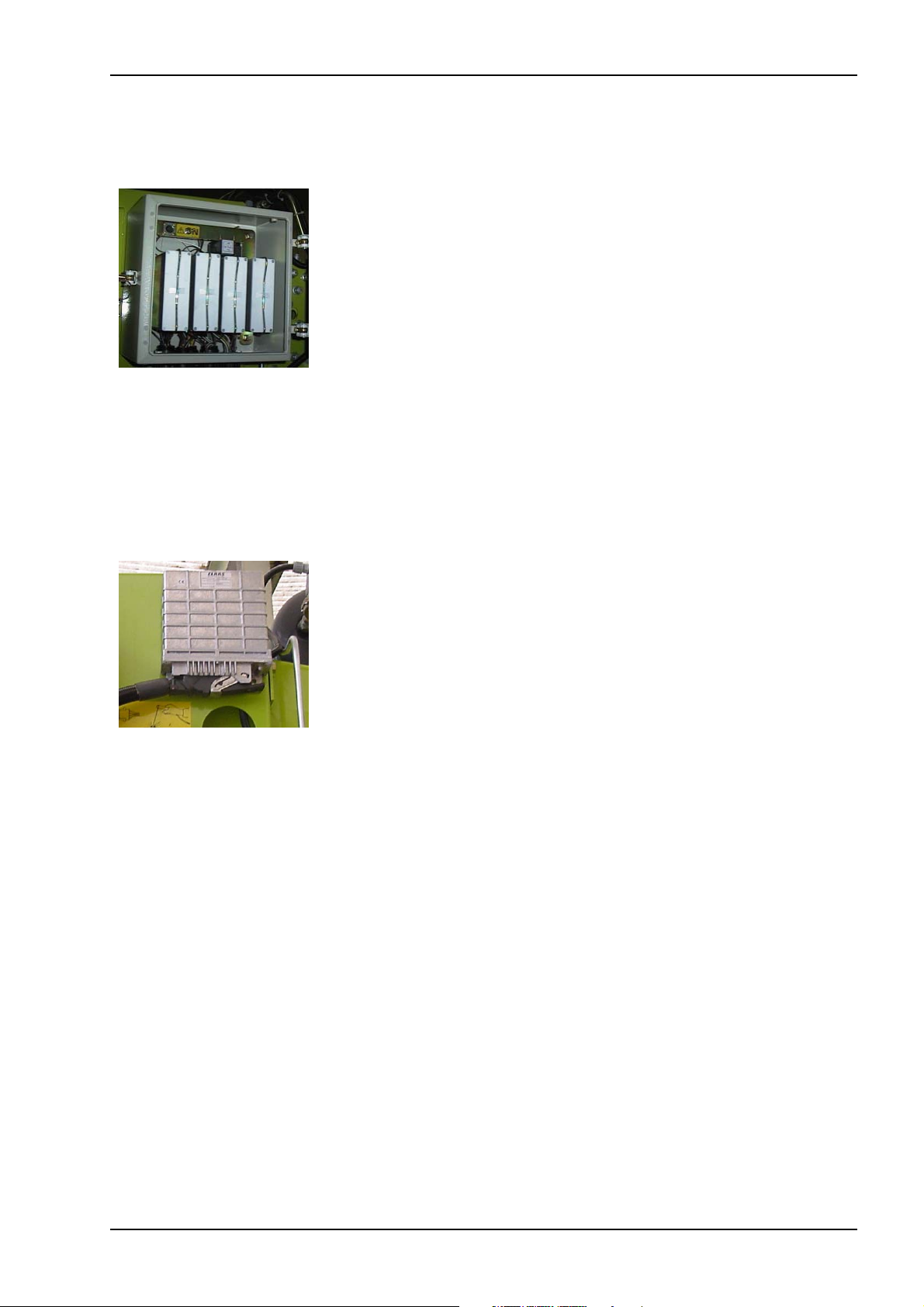
Central terminal
compartment
(from module 1 no. 835024.3)
2.1 Service menu structure . . . . .........................10
2.2 Additional information about page "Service 1" . . . . . . . . . . 11
2.3 Additional information about page "Service RC" . . . . . . . . 11
2.4 Input testing . . . . . . . . . . . . . . .........................12
2.5 Output testing . . . . . . . . . . . . .........................14
2.6 Error display . . . . . . . . . . . . . .........................18
2.7 Key test . . . . . . . . . . . . . . . . . .........................19
CCU
3.0 Control terminal service menu (on CCU module)
3.1 Service menu structure . . . . .........................20
3.2 Additional information about page "Service 1" . . . . . . . . . . 21
3.3 Additional information about page "Service RC" . . . . . . . . 21
3.4 Input testing . . . . . . . . . . . . . . .........................22
3.5 Output testing . . . . . . . . . . . . .........................24
3.6 Error display . . . . . . . . . . . . . .........................26
3.7 Key test . . . . . . . . . . . . . . . . . .........................27
4.0 Additional information
4.1 Testing the baling pressure sensor
(with Central terminal compartment) . . . . . . . . . . . . . . . . . . 28
4.2 Testing the metering wheel / bale length sensor
(with Central terminal compartment) . . . . . . . . . . . . . . . . . . . 29
4.3 General (with Central terminal compartment) . . . . . . . . . . 30
5.0 Information on replacing modules ..................31
08/2002 1
Page 4
W
Diagnosis QUADRANT 2200/ 2200 RC TIC
1.0 Control terminal service menu (up to module 1 no. 835024.2)
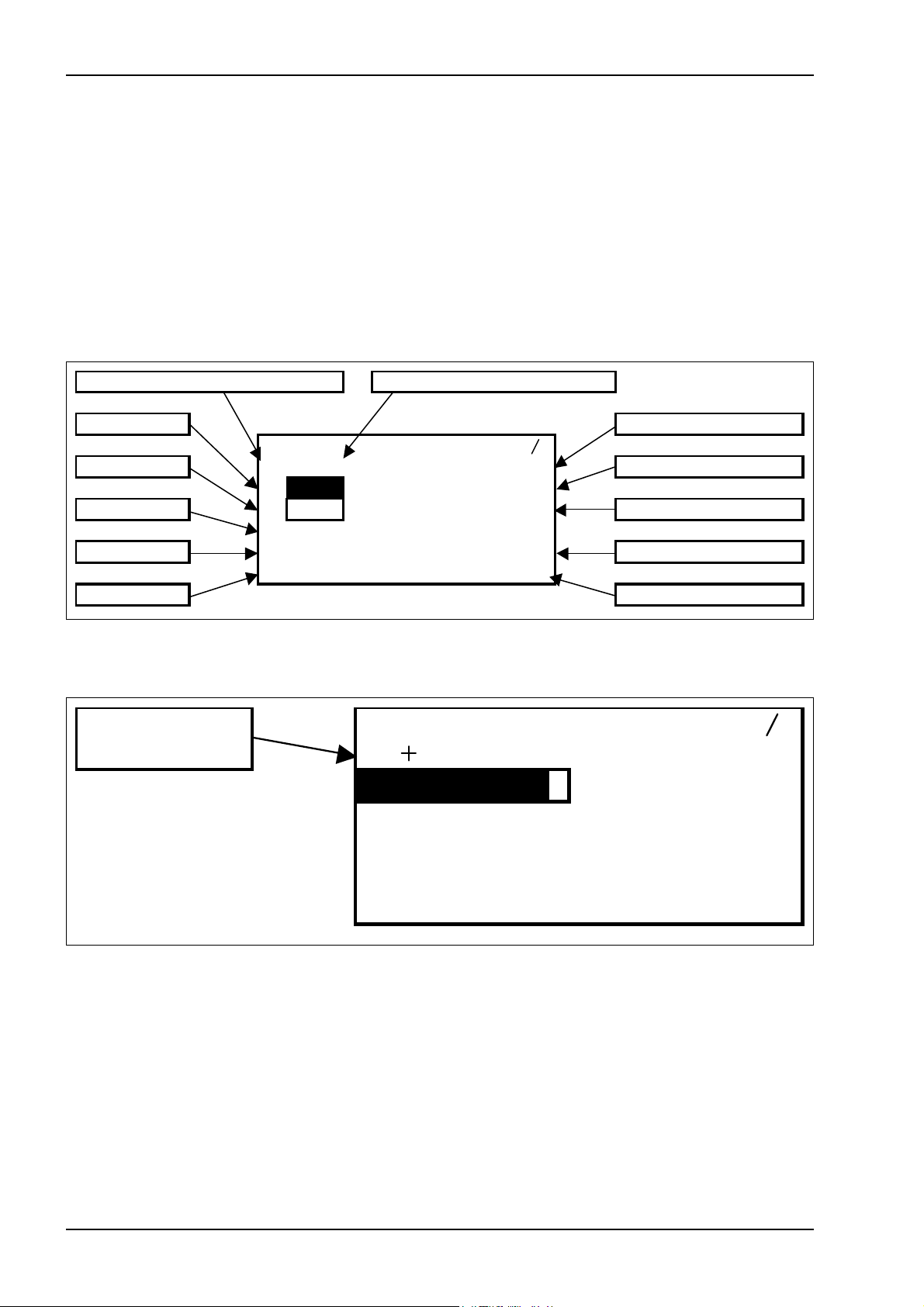
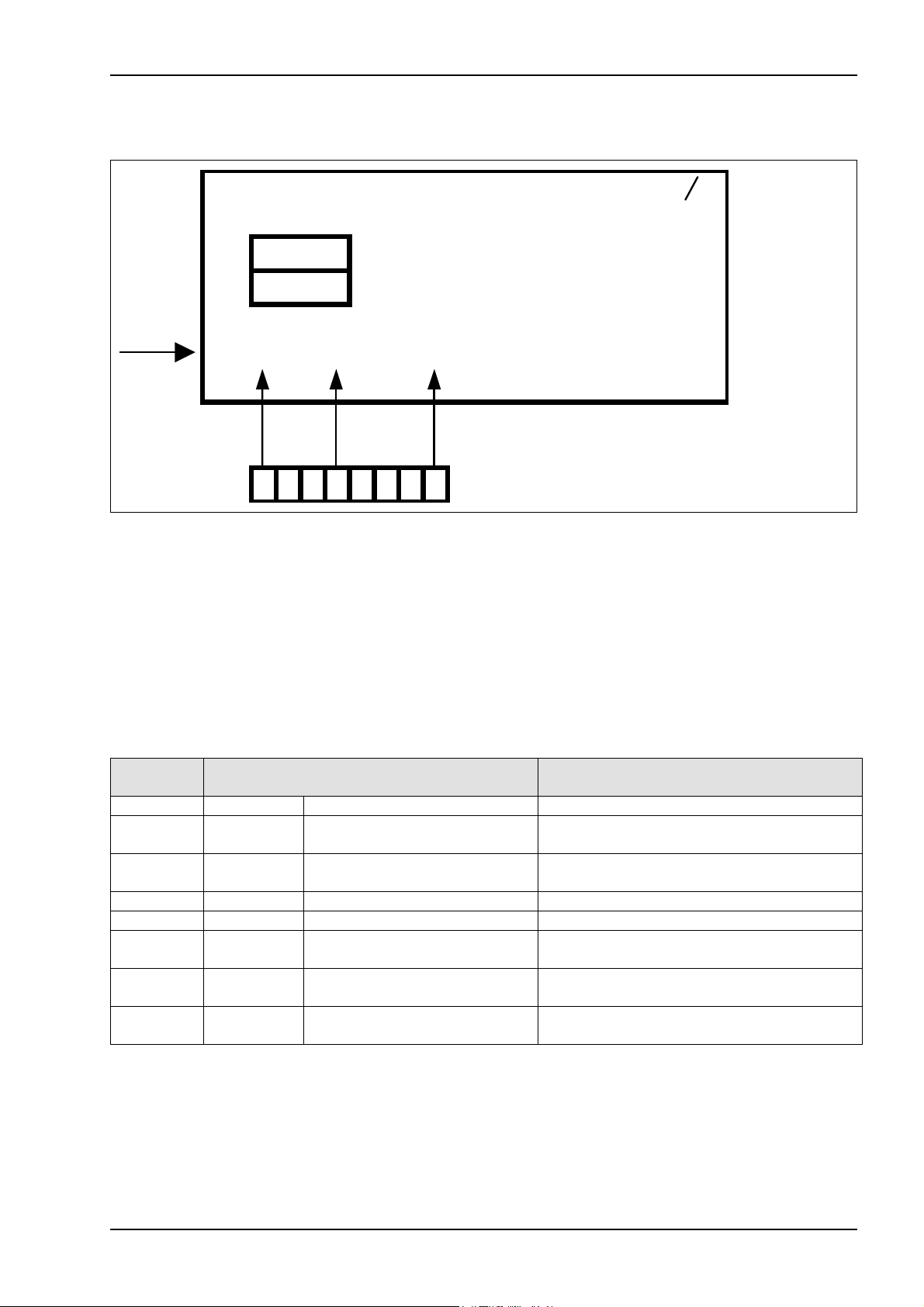
1.1 Service menu
structure
(up to module 1
no. 835024.2)
Page "8/1 (Service 1)"
Current pressure [bar] Current bale length [m]
Control unit P+ PTO shaft speed [rpm]
Service1 81
Control unit P-
Inputs
Outputs
Error
P= 0 L0 , 0 0 N0= 0
P0 25 5 N1= 0
P1 0 N2= 0
E: 00000000
A:00000000 U:11 ,6
F:00000000 FFFF
This menu serves as a tool in fault-finding. It shows the status of various
electrical components such as e.g. speed, voltage, pressure and switch
positions.
To enter the service menu, press the keys “Scroll main menu”, “Plus
key” and “Minus key” at the same time.
The following mask appears:
Feed rake speed [rpm]
Rotor speed [rpm]
Voltage [V]
Key test
Page "8/2 (Service RC)"
(press "Sub-menu" key one more time)
Cutt ing f r ame
angle
Ser vi c e RC 8 2
=20 N0= 0
255 N1= 0
N2 = 0
E:00000000
A:00000000 U:11 , 6
F:00000000 FFFF
2 08/2002
Page 5

TIC QUADRANT 2200/ 2200 RC Diagnosis
1.2 Additional information about page "8/1 (Service 1)" (up to module 1 no. 835024.2)
RemarkMenu item
The pressure in the baling chamber cylinders is displayed here in bars.(P=) Current pressure
(L) Current bale length
(N0=) PTO shaft speed
(N1=) Feed rake speed
(N2=) Rotor speed
Key test
(P0) Control unit P+
(P1) Control unit P-
The length of the bale in the baling chamber is displayed here in metres
to the second decimal point.
The calculated PTO shaft speed in revolutions per minute is displayed
here (this speed is measured by the drive speed sensor).
The feed rake speed in revolutions per minute is displayed here
(150 rpm at 1000 rpm PTO shaft speed)
The rotor speed in revolutions per minute is displayed here (140 rpm at
1000 rpm PTO shaft speed)
The supply voltage is displayed here in Volt to the first decimal point.(U:) Voltage
A combination of characters and numbers is displayed here to test the
function of the keys on the Control Terminal.
The condition of the baling pressure build-up valve is displayed here.
The displayed number is proportional with the valve actuation and may
assume values from 0 to 255.
0 = Valve not actuated
255 = Valve fully actuated
The condition of the baling pressure relief valve is displayed here. The
displayed number is proportional with the valve actuation and may
assume values from 0 to 255.
0 = Valve not actuated
255 = Valve fully actuated
(E:) Inputs
(A:) Outputs
(F:) Error
The condition of various circuits connected with the modules is
displayed here. Each numeric character corresponds to one circuit.
0 = Circuit open
1 = Circuit closed
The condition of various circuits connected with the modules is
displayed here. Each numeric character corresponds to one circuit.
0 = Circuit open
1 = Circuit closed
Malfunctions are displayed here. Each numeric character corresponds
to one error.
0 = No error
1 = Error
1.3 Additional information about page "8/2 (Service RC)" (up to module 1 no. 835024.2)
(W=) Cutting frame angle
The cutting frame angle in degrees is displayed here. The higher the
value, the wider the cutting frame is open.
08/2002 3
Page 6
Diagnosis QUADRANT 2200/ 2200 RC TIC
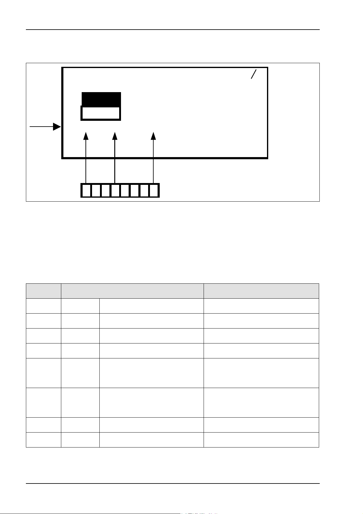
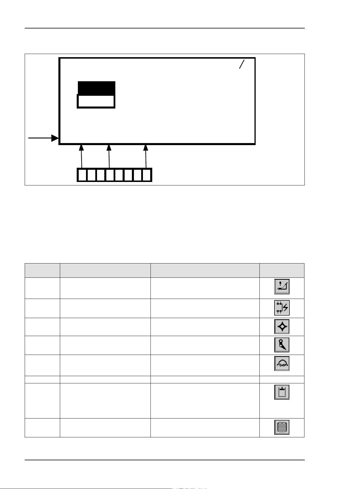
1.4 Input testing (up to module 1 no. 835024.2)
Continuity test
Ser v i c e 1 8 1
P= 0L0 , 00 N0= 0
P0 255 N1= 0
P1 0 N2= 0
E:00000000
A: 00000000 U: 11 ,6
F : 00000000 FFFF
12345678
Eight numeric characters are available for input diagnosis in line “E”, each of them being assigned to one
circuit.
The numeric characters may assume the following values:
0 = Circuit open or
1 = Circuit closed.
All numeric characters show the respective state independently of each other. Dependencies and switching
sequences which may occur in normal operation have no influence.
DisplayDesignationNumeric
character
Z11E1
Z49E2
U2E3
U1E4
B23E5
B69E7
B69E8
Twine break left/right actual value
switch
ROTOCUT knives ON actual value
switch
Retract bale ejector cylinder switch
(red)
Extend bale ejector cylinder switch
(blue)
Feed rake speed sensor (blue)
inside
Drive speed sensor (red) outside B9E6
Metering wheel / bale length sensor
signal B
Metering wheel / bale length sensor
signal A
0 = Operating status (normal)
1 = Twine break
0 = Switch not actuated
1 = Switch actuated
0 = Switch not pushed
1 = Switch pushed
0 = Switch not pushed
1 = Switch pushed
0 = Standstill
Changes between 0 and 1 when feed
rake rotates
1 = Wire ends connected
0 = Standstill
Changes between 0 and 1 when PTO
shaft rotates
1 = Wire ends connected
Changes between 0 and 1 when
metering wheel rotates
Changes between 0 and 1 when
metering wheel rotates
4 08/2002
Page 7
A
TIC QUADRANT 2200/ 2200 RC Diagnosis
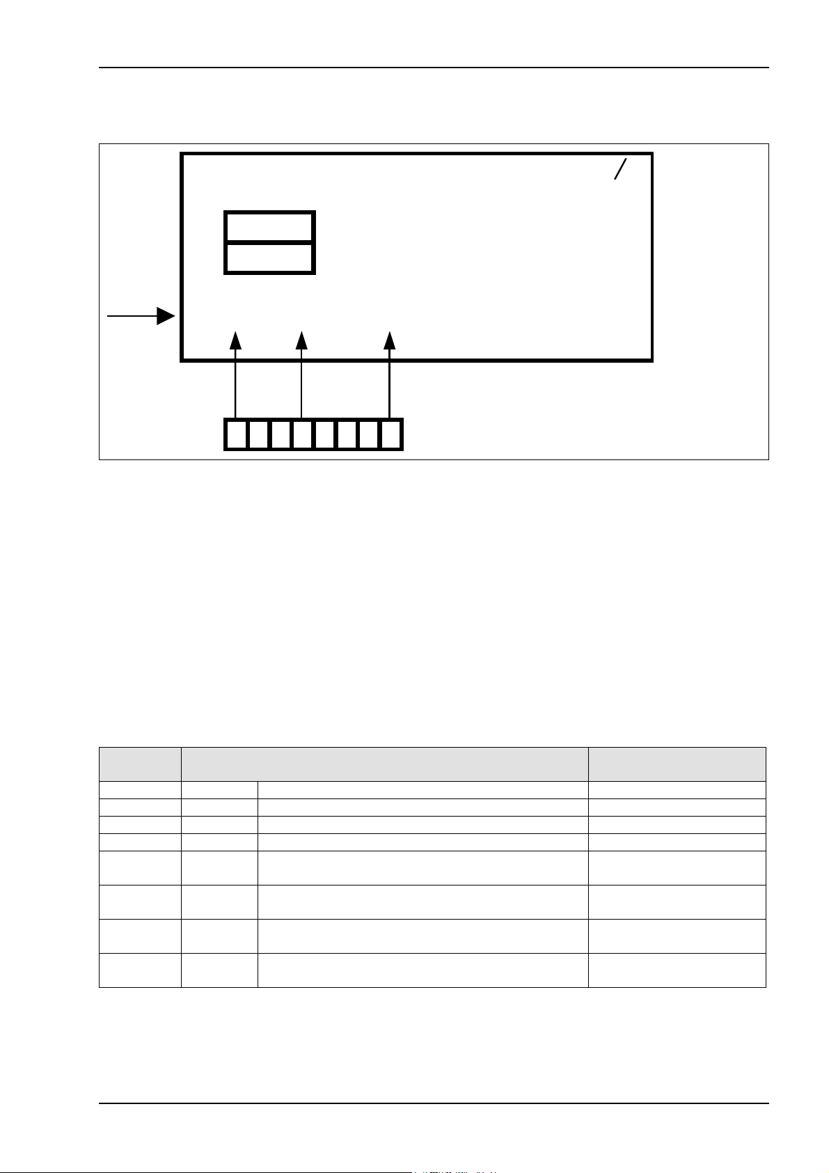
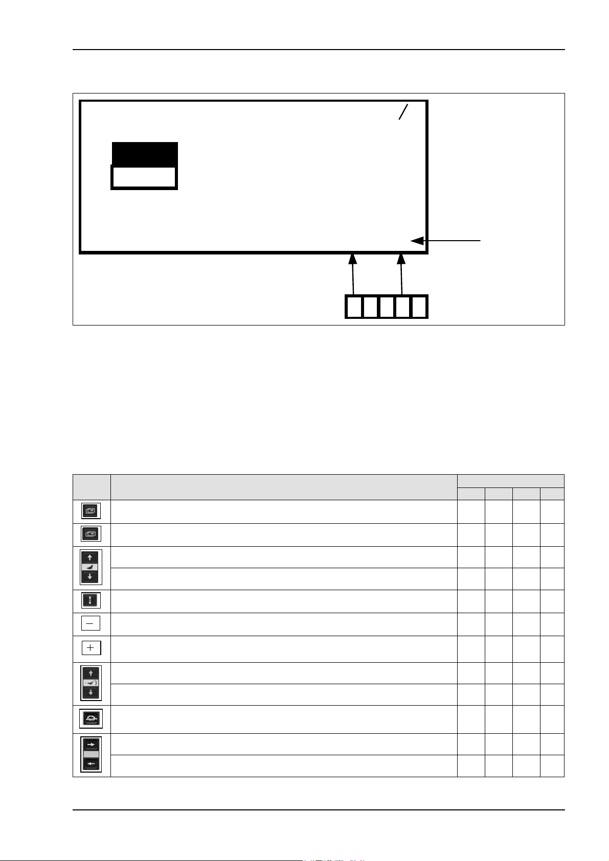
1.5 Output testing (up to module 1 no. 835024.2)
Testing the actuation by the modules
Ser v i c e 1 8 1
P= 0L0 , 00 N0= 0
P0 0 N1= 0
P1 0 N2= 0
E: 00000000
:00000000
U:11 ,6
F : 00000000 FFFF
12345678
Eight numeric characters are available for output diagnosis in line “A” on page "8 / 1 (Service 1)" and page
"8 / 2 (Service RC)", each of them being assigned to one circuit. It must be ensured that the baling pressure
solenoid valves (P0 and P1) are not activated. To achieve this, press the "Plus key" once.
The numeric characters only indicate if a solenoid valve is actuated by the corresponding module.
For diagnosis purposes, the corresponding function must be activated, i.e. the functions can be
checked only one by one.
The numeric characters may assume the following values:
0 = Solenoid valve is not actuated by the module
or
1 = Solenoid valve is actuated by the module.
Dependencies and switching sequences which may occur in normal operation have an influence.
The table below applies to page "8 / 1 (Service 1)"
DisplayDesignationNumeric
character
No functionFree NoneA1
No functionFree NoneA2
No functionFree NoneA3
No functionFree NoneA4
Retract bale ejector cylinder solenoid coilY12A5
Extend bale ejector cylinder solenoid coilY11 A6
Circulation shut-off valve solenoid coilY77 A7
Rotor blocking solenoid coilY58 A8
08/2002 5
0 = not activated
1 = activated
0 = not activated
1 = activated
0 = not activated
1 = activated
0 = not activated
1 = activated
Page 8

W
A
Diagnosis QUADRANT 2200/ 2200 RC TIC
Output testing, continued (up to module 1 no. 835024.2)
Testing the actuation by the modules
Se r v i c e RC 8 2
=20 N0= 0
255 N1= 0
N2 = 0
E: 00000000
:00000000
U:11 ,6
F : 00000000 FFFF
12345678
The table below applies to page "8 / 2 (Service RC)"
For diagnosis purposes, the corresponding function must be activated, i.e. the functions can be
checked only one by one.
DisplayDesignationNumeric
character
No functionFree NoneA1
No functionFree NoneA2
No functionFree NoneA3
No functionFree NoneA4
Close cutting frame solenoid coilY64 A5
Open cutting frame solenoid coilY63 A6
ROTOCUT knives OFF solenoid coilY54 A7
ROTOCUT knives ON solenoid coilY55 A8
0 = not activated
1 = activated
0 = not activated
1 = activated
0 = not activated
1 = activated
0 = not activated
1 = activated
6 08/2002
Page 9
A
TIC QUADRANT 2200/ 2200 RC Diagnosis
Output testing, continued (up to module 1 no. 835024.2)
Continuity test
Ser v i c e 1 8 1
P= 0L0 , 00 N0= 0
P0 0 N1 = 0
P1 0 N2 = 0
E: 00000000
:00000000
U:11 ,6
F : 00000000 FFFF
12345678
To activate this function, keep the “Minus key” pressed while in the service menu, i.e. a maximum of
eight circuits may be checked at the same time.
Eight numeric characters are available for output diagnosis in line “A”, each of them being assigned to one
circuit.
The numeric characters may assume the following values:
0 = Circuit open or
1 = Circuit closed and/or solenoid coil OK.
All numeric characters show the respective state independently of each other. Dependencies and switching
sequences which may occur in normal operation have no influence.
DisplayDesignationNumeric
character
Not relevantFree NoneA1
Rotor blocking solenoid coilY58 A2
Y77 A3
Y51 A7
Y50 A8
Circulation shut-off valve
solenoid coil
Wrapping release motor relayK92 A6
Baling pressure relief solenoid
coil
Baling pressure build-up
solenoid coil
0 = Circuit interrupted
1 = Solenoid coil circuit OK
0 = Circuit interrupted
1 = Solenoid coil circuit OK
No functionFree None A4
No functionFree None A5
0 = Circuit interrupted
1 = Relay circuit OK (85 to 86)
0 = Circuit interrupted
1 = Solenoid coil circuit OK
0 = Circuit interrupted
1 = Solenoid coil circuit OK
08/2002 7
Page 10
Diagnosis QUADRANT 2200/ 2200 RC TIC
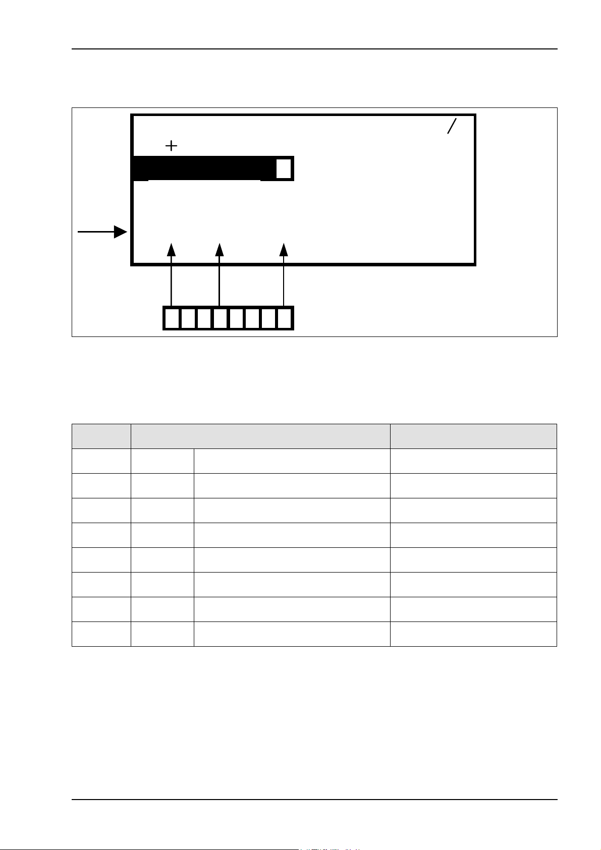
1.6 Error display (up to module 1 no. 835024.2)
Ser v i c e 1 8 1
P= 0L0 , 00 N0= 0
P0 255 N1= 0
P1 0 N2 = 0
E: 00000000
A: 00000000 U: 11 ,6
F:00000000
FFFF
12345678
Eight numeric characters are available for error display in line “F”, each of them being assigned to one error.
This function is available only on page 8/1 "Service 1".
The numeric characters may assume the following values:
0 = No error or
1 = Error.
All numeric characters show the respective state independently of each other. Dependencies and switching
sequences which may occur in normal operation have no influence.
Symbol in
work menu
character
RemarkReason Numeric
Cutting frame not closed F1
System fault (CAN bus)F2
Cutting frame should be closed, but
cutting frame position sensor indicates
an angle above 0°
No signal from CAN bus or module
defective
Rotor overloadF3
Feed rake overloadF4
Tying fault F5
F7
8 08/2002
Circulation shut-off valve
activated too long
Drive speed above 500 rpm and rotor
speed below 56 rpm
Drive speed above 500 rpm and feed
rake speed below 60 rpm
See Electric System documentation
Circuit diagram 11a, b
(Tying fault sequence diagram)
No functionFree F6
Circulation shut-off valve activated
longer than allowed in connection with
baling pressure build-up solenoid coil
(more than 50 % actuated time within
3 min.)
Twine break switch contactTwine break F8
Page 11
TIC QUADRANT 2200/ 2200 RC Diagnosis
1.7 Key test (up to module 1 no. 835024.2)
Ser v i c e 1 8 1
P= 0L0 , 00 N0= 0
P0 255 N1= 0
P1 0 N2 = 0
E:00000000
A:00000000 U:11 ,6
F : 00000000
FFFF
12345
Four numeric characters are available for key testing in line (1) shown above.
Pushing a key on the Control Terminal produces one of the combinations of numbers and characters shown
below which allow checking the function.
The character “G” at the 5
digit remains free.
Example: When the central lubrication system is active and the “Minus” key is pressed, the numeric
characters read “FDFFG”. If the central lubrication system is not active and the “Minus key” is
pressed, the numeric characters read “FDFF”.
th
digit indicates if the central lubrication system is currently active, otherwise this
DisplayDesignationKey
4321
FFFEScroll through main menu
FFFD Scroll through second screen
FFFBROTOCUT knives ON
FFF7ROTOCUT knives OFF
FFEFBuild up / relieve baling pressure
FFDFMinus
FDFFPlus
FFBFClose cutting frame
FF7FOpen cutting frame
FEFFManual tying
FBFFRight arrow key
F7FFLeft arrow key
08/2002 9
Page 12

W
Diagnosis QUADRANT 2200/ 2200 RC TIC
2.0 Control terminal service menu (from module 1 no. 835024.3)
2.1 Service menu
structure
(from module 1
no. 835024.3)
Page "8/1 (Service 1)"
Current pressure [bar] Current bale length [m]
Control unit P+ PTO shaft speed [rpm]
Service1 81
Control unit P-
Inputs
Outputs
Error
P= 0 L0 , 0 0 N0= 0
P0 25 5 N1= 0
P1 0 N2= 0
E: 00000000
A:00000000 U:11 ,6
F:00000000 FFFF
This menu serves as a tool in fault-finding. It shows the status of various
electrical components such as e.g. speed, voltage, pressure, switch
positions.
To enter the service menu, press the keys “Scroll main menu”, “Plus
key” and “Minus key” at the same time.
The following mask appears:
Feed rake speed [rpm]
Rotor speed [rpm]
Voltage [V]
Key test
Page "8/2 (Service RC)"
(press "Sub-menu" key one more time)
Cutting
frame angle
Ser vi c e RC 8 2
=20 N0= 0
255 N1= 0
N2 = 0
E:00000000
A:00000000 U:11 , 6
F:00000000 FFFF
10 08/2002
Page 13

TIC QUADRANT 2200/ 2200 RC Diagnosis
2.2 Additional information about page "8/1 (Service 1)" (from module 1 no. 835024.3)
Remark Menu item
The pressure in the baling chamber cylinders is displayed here in bars.(P=) Current pressure
(L) Current bale length
(N0=) PTO shaft speed
(N1=) Feed rake speed
(N2=) Rotor speed
Key test
(P0) Control unit P+
(P1) Control unit P-
The length of the bale in the baling chamber is displayed here in metres
to the second decimal point.
The calculated PTO shaft speed in revolutions per minute is displayed
here (this speed is measured by the drive speed sensor).
The feed rake speed in revolutions per minute is displayed here
(150 rpm at 1000 rpm PTO shaft speed)
The rotor speed in revolutions per minute is displayed here (140 rpm at
1000 rpm PTO shaft speed)
The supply voltage is displayed here in Volt to the first decimal point.(U:) Voltage
A combination of characters and numbers is displayed here to test the
function of the keys on the Control Terminal.
The condition of the baling pressure build-up valve is displayed here.
The displayed number is proportional with the valve actuation and may
assume values from 0 to 255.
0 = Valve not actuated
255 = Valve fully actuated
The condition of the baling pressure relief valve is displayed here. The
displayed number is proportional with the valve actuation and may
assume values from 0 to 255.
0 = Valve not actuated
255 = Valve fully actuated
(E:) Inputs
(A:) Outputs
(F:) Error
The condition of various circuits connected with the modules is
displayed here. Each numeric character corresponds to one circuit.
0 = Circuit open
1 = Circuit closed
The condition of various circuits connected with the modules is
displayed here. Each numeric character corresponds to one circuit.
0 = Circuit open
1 = Circuit closed
Malfunctions are displayed here. Each numeric character corresponds
to one error.
0 = No error
1 = Error
2.3 Additional information about page "8/2 (Service RC)" (up to module 1 no. 835024.3)
(W=) Cutting frame angle
The cutting frame angle in degrees is displayed here. The higher the
value, the wider the cutting frame is open.
08/2002 11
Page 14

Diagnosis QUADRANT 2200/ 2200 RC TIC
2.4 Input testing (from module 1 no. 835024.3)
Continuity test
Ser v i c e 1 8 1
P= 0L0 , 00 N0= 0
P0 255 N1= 0
P1 0 N2 = 0
E:00000000
A: 00000000 U: 11 ,6
F : 00000000 FFFF
12345678
Eight numeric characters are available for input diagnosis in line “E” on page "8 / 1 (Service 1)" and page
"8 / 2 (Service RC)", each of them being assigned to one circuit.
The numeric characters may assume the following values:
0 = Circuit open or
1 = Circuit closed.
All numeric characters show the respective state independently of each other. Dependencies and switching
sequences which may occur in normal operation have no influence.
The table below applies to page "8 / 1 (Service 1)"
DisplayDesignationNumeric
character
Emergency operation switchU5 E1
Z11 E3
Z63 E4
B23 E5
B9 E6
B69 E7
B69 E8
Twine break left/right actual
value switch
Tying system monitoring actual
value switch
Feed rake speed sensor (blue)
inside
Drive speed sensor (red)
outside
Metering wheel / bale length
sensor - signal B
Metering wheel / bale length
sensor - signal A
1 = Normal operation switch
0 = Emergency operation switch
No functionFree None E2
0 = Operating status (normal)
1 = Twine break
0 = Switch pushed
1 = Switch not pushed
0 = Standstill
Changes between 0 and 1 when feed rake
rotates
1 = Wire ends connected
0 = Standstill
Changes between 0 and 1 when feed rake
rotates
1 = Wire ends connected
Changes between 0 and 1 when metering
wheel rotates
Changes between 0 and 1 when metering
wheel rotates
12 08/2002
Page 15

R
W
TIC QUADRANT 2200/ 2200 RC Diagnosis
Input testing, continued (from module 1 no. 835024.3)
Continuity test
Se r vi c e
C82
=20 N0= 0
255 N1= 0
E:00000000
A: 00000000 U: 11 ,6
F : 00000000 FFFF
12345678
The table below applies to page "8 / 2 (Service RC)"
character
Z49 E4
Z56 E5
U2 E6
U1 E7
ROTOCUT knives ON actual
value switch
Flywheel brake actual value
switch
Retract bale ejector cylinder
switch - (red)
Extend bale ejector cylinder
switch U2 - (blue)
Rotor speed sensor B24 E8
N2 = 0
DisplayDesignationNumeric
No functionFree None E1
No functionFree None E2
No functionFree None E3
0 = Switch not actuated
1 = Switch actuated
1 = Switch actuated
0 = Switch not actuated
1 = Switch actuated
0 = Switch not actuated
1 = Switch actuated
0 = Switch not actuated
0 = Standstill
Changes between 0 and 1 when rotor rotates
1 = Wire ends connected
08/2002 13
Page 16

A
Diagnosis QUADRANT 2200/ 2200 RC TIC
2.5 Output testing (from module 1 no. 835024.3)
Testing the actuation by the modules
Ser v i c e 1 8 1
P= 0L0 , 00 N0= 0
P0 0 N1 = 0
P1 0 N2 = 0
E: 00000000
:00000000
U:11 ,6
F : 00000000 FFFF
12345678
Eight numeric characters are available for output diagnosis in line “A” on page "8 / 1 (Service 1)" and page
"8 / 2 (Service RC)", each of them being assigned to one circuit.
It must be ensured that the baling pressure solenoid valves (P0 and P1) are not activated. To achieve this,
press the "Plus key" once.
The numeric characters only indicate if a solenoid valve is actuated by the corresponding module.
For diagnosis purposes, the corresponding function must be activated, i.e. the functions can be
checked only one by one.
The numeric characters may assume the following values:
0 = Solenoid valve is not actuated by the module
or
1 = Solenoid valve is actuated by the module.
Dependencies and switching sequences which may occur in normal operation have an influence.
The table below applies to page "8 / 1 (Service 1)"
DisplayDesignationNumeric
character
No functionFree None A1
No functionFree None A2
No functionFree None A3
Rotor blocking solenoid coilY58 A4
Y77 A5
Y51 A7
Y50 A8
14 08/2002
Circulation shut-off valve
solenoid coil
Tying release motor relayK92 A6
Baling pressure relief solenoid
coil
Baling pressure build-up
solenoid coil
0 = not activated
1 = activated
0 = not activated
1 = activated
0 = not activated
1 = activated
0 = not activated
1 = activated
0 = not activated
1 = activated
Page 17
W
A
TIC QUADRANT 2200/ 2200 RC Diagnosis
Output testing, continued (from module 1 no. 835024.3)
Testing the actuation by the modules
Se r v i c e RC 8 2
=20 N0= 0
255 N1= 0
N2 = 0
E: 00000000
:00000000
U:11 ,6
F : 00000000 FFFF
12345678
The table below applies to page "8 / 2 (Service RC)"
For diagnosis purposes, the corresponding function must be activated, i.e. the functions can be
checked only one by one.
DisplayDesignationNumeric
character
Open cutting frame solenoid coilY63 A1
Close cutting frame solenoid coilY64 A2
ROTOCUT knives ON solenoid coilY55 A3
ROTOCUT knives OFF solenoid coilY54 A4
Central lubrication system motorM25 A5
Retract bale ejector cylinder solenoid coilY12 A6
Extend bale ejector cylinder solenoid coilY11 A7
Y31 A8
Knotter cleaning solenoid coil
(when set to 2.5 s blowing time)
0 = not activated
1 = activated
0 = not activated
1 = activated
0 = not activated
1 = activated
0 = not activated
1 = activated
0 = not activated
1 = activated
0 = not activated
1 = activated
0 = not activated
1 = activated
0 = not activated
1 = activated
08/2002 15
Page 18

A
Diagnosis QUADRANT 2200/ 2200 RC TIC
Output testing, continued (from module 1 no. 835024.3)
Continuity test
Ser v i c e 1 8 1
P= 0L0 , 00 N0= 0
P0 0 N1 = 0
P1 0 N2 = 0
E: 00000000
:00000000
U:11 ,6
F : 00000000 FFFF
12345678
To activate this function, keep the “Minus key” pressed while in the service menu, i.e. a maximum of
eight circuits may be checked at the same time.
Eight numeric characters are available for output diagnosis in line “A” on page "8 / 1 (Service 1)" and page
"8 / 2 (Service RC)", each of them being assigned to one circuit.
The numeric characters may assume the following values:
0 = Circuit open or
1 = Circuit closed and/or solenoid coil OK.
All numeric characters show the respective state independently of each other. Dependencies and switching
sequences which may occur in normal operation have no influence.
The table below applies to page "8 / 1 (Service 1)"
DisplayDesignationNumeric
character
No functionFree None A1
No functionFree None A2
No functionFree None A3
Rotor blocking solenoid coilY58 A4
Y77 A5
Y51 A7
Y50 A8
16 08/2002
Circulation shut-off valve
solenoid coil
Tying release motor relayK92 A6
Baling pressure relief solenoid
coil
Baling pressure build-up
solenoid coil
0 = Circuit interrupted
1 = Solenoid coil circuit OK
0 = Circuit interrupted
1 = Solenoid coil circuit OK
0 = Circuit interrupted
1 = Relay circuit OK (85 to 86)
0 = Circuit interrupted
1 = Solenoid coil circuit OK
0 = Circuit interrupted
1 = Solenoid coil circuit OK
Page 19

W
A
TIC QUADRANT 2200/ 2200 RC Diagnosis
Output testing, continued (from module 1 no. 835024.3)
Continuity test
Se r v i c e RC 8 2
=20 N0= 0
255 N1= 0
N2 = 0
E: 00000000
:00000000
U:11 ,6
F : 00000000 FFFF
12345678
The table below applies to page "8 / 2 (Service RC)"
To activate this function, keep the “Minus key” pressed while in the service menu, i.e. a maximum of
eight circuits may be checked at the same time.
DisplayDesignationNumeric
character
Open cutting frame solenoid coilY63 A1
Close cutting frame solenoid coilY64 A2
ROTOCUT knives ON solenoid coilY55 A3
ROTOCUT knives OFF solenoid coilY54 A4
Central lubrication system motorM25 A5
Y12 A6
Y11 A7
Y31 A8
Retract bale ejector cylinder
solenoid coil
Extend bale ejector cylinder
solenoid coil
Knotter cleaning solenoid coil (when
set to 2.5 s blowing time)
0 = Circuit interrupted
1 = Solenoid coil circuit OK
0 = Circuit interrupted
1 = Solenoid coil circuit OK
0 = Circuit interrupted
1 = Solenoid coil circuit OK
0 = Circuit interrupted
1 = Solenoid coil circuit OK
0 = Circuit interrupted
1 = Solenoid coil circuit OK
0 = Circuit interrupted
1 = Solenoid coil circuit OK
0 = Circuit interrupted
1 = Solenoid coil circuit OK
0 = Circuit interrupted
1 = Solenoid coil circuit OK
08/2002 17
Page 20

Diagnosis QUADRANT 2200/ 2200 RC TIC
2.6 Error display (from module 1 no. 835024.3)
Ser v i c e 1 8 1
P= 0L0 , 00 N0= 0
P0 255 N1= 0
P1 0 N2 = 0
E: 00000000
A: 00000000 U: 11 ,6
F:00000000
FFFF
12345678
Eight numeric characters are available for error display in line “F”, each of them being assigned to one error.
This function is available only on page 8/1 "Service 1".
The numeric characters may assume the following values:
0 = No error or
1 = Error.
All numeric characters show the respective state independently of each other. Dependencies and switching
sequences which may occur in normal operation have no influence.
Symbol in
work menu
character
RemarkReason Numeric
Cutting frame not closed F1
Cutting frame should be closed, but cutting
frame position sensor indicates an angle
above 0°
No signal from CAN bus or module defectiveSystem fault (CAN bus)F2
Rotor overloadF3
Feed rake overloadF4
Tying fault F5
F7
18 08/2002
Circulation shut-off valve
activated too long
Drive speed above 500 rpm and rotor speed
below 56 rpm
Drive speed above 500 rpm and feed rake
speed below 60 rpm
See Electric System documentation
Circuit diagram 11a, b
(Tying fault sequence diagram)
No functionFree F6
Circulation shut-off valve activated longer
than allowed in connection with baling
pressure build-up solenoid coil (more than
50 % actuated time within 3 min.)
Twine break switch contactTwine break F8
Page 21

TIC QUADRANT 2200/ 2200 RC Diagnosis
2.7 Key test (from module 1 no. 835024.3)
Ser v i c e 1 8 1
P= 0L0 , 00 N0= 0
P0 255 N1= 0
P1 0 N2 = 0
E:00000000
A:00000000 U:11 ,6
F : 00000000
FFFF
12345
Four numeric characters are available for key testing in line (1) shown above.
Pushing a key on the Control Terminal produces one of the combinations of numbers and characters shown
below which allow checking the function.
The character “G” at the 5
digit remains free.
Example: When the central lubrication system is active and the “Minus” key is pressed, the numeric
characters read “FDFFG”. If the central lubrication system is not active and the “Minus key” is
pressed, the numeric characters read “FDFF”.
th
digit indicates if the central lubrication system is currently active, otherwise this
DisplayDesignationKey
4321
FFFEScroll through main menu
FFFD Scroll through second screen
FFFBROTOCUT knives ON
FFF7ROTOCUT knives OFF
FFEFBuild up / relieve baling pressure
FFDFMinus
FDFFPlus
FFBFClose cutting frame
FF7FOpen cutting frame
FEFFManual tying
FBFFRight arrow key
F7FFLeft arrow key
08/2002 19
Page 22

W
Diagnosis QUADRANT 2200/ 2200 RC TIC
3.0 Control terminal service menu (on CCU module)
3.1 Service menu
structure (on
CCU module)
Page "8/1 (Service 1)"
Current pressure [bar] Current bale length [m]
Control unit P+ PTO shaft speed [rpm]
Service1 81
Control unit P-
Inputs
Outputs
Error
P= 0 L0 , 0 0 N0= 0
P0 25 5 N1= 0
P1 0 N2= 0
E: 00000000
A:00000000 U:11 ,6
F:00000000 FFFF
This menu serves as a tool in fault-finding. It shows the status of various
electrical components such as e.g. speed, voltage, pressure, switch
positions.
To enter the service menu, press the keys “Scroll main menu”, “Plus
key” and “Minus key” at the same time.
The following mask appears:
Feed rake speed [rpm]
Rotor speed [rpm]
Voltage [V]
Key test
Page "8/2 (Service RC)"
(press "Sub-menu" key one more time)
Cutting
frame angle
Ser vi c e RC 8 2
=20 N0= 0
255 N1= 0
N2 = 0
E:00000000
A:00000000 U:11 , 6
F:00000000 FFFF
20 08/2002
Page 23

TIC QUADRANT 2200/ 2200 RC Diagnosis
3.2 Additional information about page "8/1 (Service 1)" (on CCU module)
Remark Menu item
The pressure in the baling chamber cylinders is displayed here in bars.(P=) Current pressure
(L) Current bale length
(N0=) PTO shaft speed
(N1=) Feed rake speed
(N2=) Rotor speed
Key test
(P0) Control unit P+
(P1) Control unit P-
The length of the bale in the baling chamber is displayed here in metres
to the second decimal point.
The calculated PTO shaft speed in revolutions per minute is displayed
here (this speed is measured by the drive speed sensor).
The feed rake speed in revolutions per minute is displayed here
(150 rpm at 1000 rpm PTO shaft speed)
The rotor speed in revolutions per minute is displayed here (140 rpm at
1000 rpm PTO shaft speed)
The supply voltage is displayed here in Volt to the first decimal point.(U:) Voltage
A combination of characters and numbers is displayed here to test the
function of the keys on the Control Terminal.
The condition of the baling pressure build-up valve is displayed here.
The displayed number is proportional with the valve actuation and may
assume values from 0 to 255.
0 = Valve not actuated
255 = Valve fully actuated
The condition of the baling pressure relief valve is displayed here. The
displayed number is proportional with the valve actuation and may
assume values from 0 to 255.
0 = Valve not actuated
255 = Valve fully actuated
(E:) Inputs
(A:) Outputs
(F:) Error
The condition of various circuits connected with the modules is
displayed here. Each numeric character corresponds to one circuit.
0 = Circuit open
1 = Circuit closed
The condition of various circuits connected with the modules is
displayed here. Each numeric character corresponds to one circuit.
0 = Circuit open
1 = Circuit closed
Malfunctions are displayed here. Each numeric character corresponds
to one error.
0 = No error
1 = Error
3.3 Additional information about page "8/2 (Service RC)" (on CCU module)
(W=) Cutting frame angle
The cutting frame angle in degrees is displayed here. The higher the
value, the wider the cutting frame is open.
08/2002 21
Page 24

Diagnosis QUADRANT 2200/ 2200 RC TIC
3.4 Input testing (on CCU module)
Continuity test
Ser v i c e 1 8 1
P= 0L0 , 00 N0= 0
P0 255 N1= 0
P1 0 N2 = 0
E:00000000
A: 00000000 U: 11 ,6
F : 00000000 FFFF
12345678
Eight numeric characters are available for input diagnosis in line “E” on page "8 / 1 (Service 1)", each of them
being assigned to one circuit.
The numeric characters may assume the following values:
0 = Circuit open or
1 = Circuit closed.
All numeric characters show the respective state independently of each other. Dependencies and switching
sequences which may occur in normal operation have no influence.
The table below applies to page "8 / 1 (Service 1)"
DisplayDesignationNumeric
character
Z11 E1
Z63 E2
B69 E3
B69 E4
B23 E5
B9 E6
Twine break left/right actual
value switch
Tying system monitoring actual
value switch
Metering wheel / bale length
sensor - signal B
Metering wheel / bale length
sensor - signal A
Feed rake speed sensor
(green) inside
Drive speed sensor (red)
outside
Rotor speed sensorB24 E7
Crop humidity sensorB38 E8
1 = Twine break
0 = No twine break
0 = Switch pushed
1 = Switch not pushed
Changes between 0 and 1 when metering wheel
rotates
Changes between 0 and 1 when metering wheel
rotates
1 = Plug removed
Changes between 0 and 1 when feed rake rotates
0 = Wire ends connected
1 = Plug removed
Changes between 0 and 1 when feed rake rotates
0 = Wire ends connected
1 = Plug removed
Changes between 0 and 1 when feed rake rotates
0 = Wire ends connected
0 = Plug removed
Changes between 0 and 1 when sensor OK
1 = Wire ends connected
22 08/2002
Page 25

R
W
TIC QUADRANT 2200/ 2200 RC Diagnosis
Input testing, continued (on CCU module)
Continuity test
Se r vi c e
C82
=20 N0= 0
255 N1= 0
E:00000000
A: 00000000 U: 11 ,6
F : 00000000 FFFF
12345678
The table below applies to page "8 / 2 (Service RC)"
character
Flywheel brake actual value switchZ56 E3
U1 E4
U2 E5
Z49 E8
Extend bale ejector cylinder switch
(blue)
Retract bale ejector cylinder switch
(red)
Bale discharge sensorB101 E6
ROTOCUT knives ON actual value
switch
N2 = 0
DisplayDesignationNumeric
No functionFree None E1
No functionFree None E2
1 = Switch actuated
0 = Switch not actuated
1 = Switch actuated
0 = Switch not actuated
1 = Switch actuated
0 = Switch not actuated
1 = Sheet metal in front of sensor
0 = No sheet metal in front of sensor
No functionFree None E7
0 = Switch actuated
1 = Switch not actuated
08/2002 23
Page 26

A
Diagnosis QUADRANT 2200/ 2200 RC TIC
3.5 Output testing (on CCU module)
Testing the actuation by the modules
Ser v i c e 1 8 1
P= 0L0 , 00 N0= 0
P0 0 N1 = 0
P1 0 N2 = 0
E: 00000000
:00000000
U:11 ,6
F : 00000000 FFFF
12345678
Eight numeric characters are available for output diagnosis in line “A” on page "8 / 1 (Service 1)" and page
"8 / 2 (Service RC)", each of them being assigned to one circuit.
It must be ensured that the baling pressure solenoid valves (P0 and P1) are not activated. To achieve this,
press the "Plus key" once.
The numeric characters only indicate if a solenoid valve is actuated by the corresponding module.
For diagnosis purposes, the corresponding function must be activated, i.e. the functions can be
checked only one by one.
The numeric characters may assume the following values:
0 = Solenoid valve is not actuated by the module or
1 = Solenoid valve is actuated by the module.
Dependencies and switching sequences which may occur in normal operation have an influence.
The table below applies to page "8 / 1 (Service 1)"
DisplayDesignationNumeric
character
Open cutting frame solenoid coilY63 A1
Close cutting frame solenoid coilY64 A2
ROTOCUT knives OFF solenoid coilY54 A3
Central lubrication system motorM25 A4
Extend bale ejector cylinder solenoid coil Y11 A5
Retract bale ejector cylinder solenoid coil Y12 A6
Rotor blocking solenoid coilY58 A7
Circulation shut-off valve solenoid coilY77 A8
24 08/2002
0 = not activated
1 = activated
0 = not activated
1 = activated
0 = not activated
1 = activated
0 = not activated
1 = activated
0 = not activated
1 = activated
0 = not activated
1 = activated
0 = not activated
1 = activated
0 = not activated
1 = activated
Page 27

A
TIC QUADRANT 2200/ 2200 RC Diagnosis
Output testing, continued (on CCU module)
Testing the actuation by the modules
Ser v i c e 1 8 1
P= 0L0 , 00 N0= 0
P0 0 N1 = 0
P1 0 N2 = 0
E: 00000000
:00000000
U:11 ,6
F : 00000000 FFFF
12345678
The table below applies to page "8 / 2 (Service RC)"
For diagnosis purposes, the corresponding function must be activated, i.e. the functions can be
checked only one by one.
DisplayDesignationNumeric
character
No functionFree None A1
No functionFree None A2
No functionFree None A3
ROTOCUT knives ON solenoid coilY55 A4
Tying release motor relayK92 A5
Baling pressure relief solenoid coilY51 A6
Baling pressure build-up solenoid coilY50 A7
Y31 A8
Knotter cleaning solenoid coil
(when set to 2.5 s blowing time)
0 = not activated
1 = activated
0 = not activated
1 = activated
0 = not activated
1 = activated
0 = not activated
1 = activated
0 = not activated
1 = activated
08/2002 25
Page 28

Diagnosis QUADRANT 2200/ 2200 RC TIC
3.6 Error display (on CCU module)
Ser v i c e 1 8 1
P= 0L0 , 00 N0= 0
P0 255 N1= 0
P1 0 N2 = 0
E: 00000000
A: 00000000 U: 11 ,6
F:00000000
FFFF
12345678
Eight numeric characters are available for error display in line “F”, each of them being assigned to one error.
This function is available only on page 8/1 "Service 1".
The numeric characters may assume the following values:
0 = No error or
1 = Error.
All numeric characters show the respective state independently of each other. Dependencies and switching
sequences which may occur in normal operation have no influence.
Symbol in
work menu
character
F1
F2
Cutting frame not
closed
bus)
RemarkReason Numeric
Cutting frame should be closed, but cutting frame
position sensor indicates an angle above 0°
No signal from CAN bus or module defectiveSystem fault (CAN
Rotor overloadF3
Feed rake overloadF4
Tying fault F5
F7
26 08/2002
Circulation shut-off
valve activated too
long
Overload
Drive speed above 500 rpm and rotor speed
below 56 rpm
Drive speed above 500 rpm and feed rake speed
below 60 rpm
See Electric System documentation
Circuit diagram 11c
(Tying fault sequence diagram)
No functionFree F6
Circulation shut-off valve activated longer than
allowed in connection with baling pressure
build-up solenoid coil (more than 50 % actuated
time within 3 min.)
Twine break switch contactTwine break F8
∆ P > 15 bars in 125 ms (module 3)
∆ P > 20 bars in 125 ms (module 4)
Page 29

TIC QUADRANT 2200/ 2200 RC Diagnosis
3.7 Key test (on CCU module)
Ser v i c e 1 8 1
P= 0L0 , 00 N0= 0
P0 255 N1= 0
P1 0 N2 = 0
E:00000000
A:00000000 U:11 ,6
F : 00000000
FFFF
12345
Four numeric characters are available for key testing in line (1) shown above.
Pushing a key on the Control Terminal produces one of the combinations of numbers and characters shown
below which allow checking the function.
The character “G” at the 5th digit indicates if the central lubrication system is currently active, otherwise this
digit remains free.
Example: When the central lubrication system is active and the “Minus” key is pressed, the numeric
characters read “FDFFG”. If the central lubrication system is not active and the “Minus key” is
pressed, the numeric characters read “FDFF”.
DisplayDesignationKey
4321
FFFEScroll through main menu
FFFD Scroll through second screen
FFFBROTOCUT knives ON
FFF7ROTOCUT knives OFF
FFEFBuild up / relieve baling pressure
FFDFMinus
FDFFPlus
FFBFClose cutting frame
FF7FOpen cutting frame
FEFFManual tying
FBFFRight arrow key
F7FFLeft arrow key
08/2002 27
Page 30

Diagnosis QUADRANT 2200/ 2200 RC TIC
4.0 Additional information
4.1 Testing the
baling pressure
sensor (B56)
(with central
terminal
compartment)
To check the actual baling pressure, a pressure gauge must be
connected to the measuring port of the baling chamber.
The pressure pre-set in the CCT should not deviate more than +/- 7 bar
from the actual value.
During this test, the pressure sensor should transmit a signal voltage of
approx. 1 V (0 bar baling pressure) and approx. 3V (220 bar baling
pressure) which is proportional to the baling pressure to module 1.
For testing purposes, the voltage between module slot 2 (earth) and
module slot 21 (signal from pressure sensor) can be checked on the
plug of module 1 after removing the module.
If these values are not reached, the supply voltage of the pressure
sensor should be checked.
This can be measured between module slot 1 and 3 of the plug on the
baler side. The value should correspond with the system voltage of the
tractor (approx. 12 V).
28 08/2002
Page 31

TIC QUADRANT 2200/ 2200 RC Diagnosis
4.2 Testing the
metering
wheel / bale
length sensor
(B69)
(with central
terminal
compartment)
Metering wheel in counting direction
A)
The service menu of the Control Terminal (see description in chapter 3.)
can be used to check the metering wheel sensor.
The pulses of the metering wheel sensor can be tested individually in the
service menu in the "Inputs" line. The numeric characters 7 and 8
change between “1” and “0” in a given pattern, which allows to identify
the sense of rotation of the metering wheel.
To this end, slowly rotate the metering wheel and watch the display in
the Control Terminal. The tables show an extract of the numeric
character sequence which is repeated while the metering wheel rotates.
Metering wheel against counting direction
B)
Sensor Sensor
1SI10 1SI11 1SI10 1SI11
00 00
01 10
11 11
10 01
B)
A)
When the numeric character sequence is displayed in this order, the
sensor is OK.
If the display does not change when the metering wheels is rotated, the
cabling to the metering wheel sensor may be checked as follows:
1. When the plug has been removed from the metering wheel, both
digits must show “0”.
2. When pins 2 and 4 of the plug are connected, digit 7 must be “1”.
3. When pins 3 and 4 of the plug are connected, digit 8 must be “1”.
4. The tractor system voltage (approx. 12V) must be measured
between pin 1 (power supply) and pin 4 (earth) of the plug on the
metering wheel sensor.
In addition, a bale length of 1.28 m should be displayed after one
rotation of the metering wheel (reset the display to zero by one tying
process before this check).
The bale length is now displayed in the service menu under “L=”.
If the length is not shown properly although the sensor and its cabling
are faultless, the problem is in the program of the modules. In this case,
the baler must be newly configured.
08/2002 29
Page 32

Diagnosis QUADRANT 2200/ 2200 RC TIC
4.3 General (with central terminal compartment)
Ejecting bales
Overload protection
Knotter cleaning
Speed sensors
CCT
Bale length display
The bale length determined by the metering wheel when ejecting bales
is saved in the baler module and added to the next bale later during
baling. This value is stored even after switching off the ignition.
The baling pressure is relieved when the bale is ejected.
When the maximum allowed ram force is exceeded, the baling pressure
is abruptly relieved. This shuts down the baling pressure control for 7
seconds. After this, the pre-set baling pressure is built up again.
The knotter is cleaned directly prior to tying the bale and after half the
bale length has been reached.
At a PTO shaft speed of approx. 350 rpm, the speed sensors (drive,
feed rake, rotor) should display a correct value.
The full scope of electronic functions is available when:
the main switch has been switched on for more than 3 seconds and
the baler speed is at least 500 rpm.
When the bale length bar in the Control Terminal remains completely
dark and when bale tying is not possible (e.g. by excessively fast
rotation of the metering wheel by hand), the tying release must be reset.
To do this, proceed as follows:
1. With the CCT switched on, turn back metering wheel until bar
stops being dark
2. Wait for approx. 10 s
3. Switch CCT off / on.
Manual tying start
To be able to carry out a manual tying start on balers from machine no.,
the metering wheel must have measured a bale length of at least
approx. 40 cm.
30 08/2002
Page 33

TIC QUADRANT 2200/ 2200 RC Diagnosis
5.0 Information on replacing modules
A backup of the module data must be created using the CDS. To do this,
start the corresponding program in the CDS.
The data are read out and saved on the CDS harddisk.
Disconnect the power supply of the machine prior to replacing
modules.
After replacing the module, the data from the CDS must be restored to
the machine.
Suitable programs are available in the diagnosis menu. This ensures
that machine-specific data will not be modified.
Do not exchange modules between machines! There is no way to
restore these data.
08/2002 31
Page 34

Diagnosis QUADRANT 2200/ 2200 RC TIC
Notes
_____________________________________________________________
_____________________________________________________________
_____________________________________________________________
_____________________________________________________________
_____________________________________________________________
_____________________________________________________________
_____________________________________________________________
_____________________________________________________________
_____________________________________________________________
_____________________________________________________________
_____________________________________________________________
_____________________________________________________________
_____________________________________________________________
_____________________________________________________________
_____________________________________________________________
_____________________________________________________________
_____________________________________________________________
_____________________________________________________________
_____________________________________________________________
_____________________________________________________________
_____________________________________________________________
_____________________________________________________________
_____________________________________________________________
_____________________________________________________________
_____________________________________________________________
_____________________________________________________________
_____________________________________________________________
_____________________________________________________________
_____________________________________________________________
_____________________________________________________________
_____________________________________________________________
_____________________________________________________________
_____________________________________________________________
_____________________________________________________________
_____________________________________________________________
_____________________________________________________________
32 08/2002
Page 35

Following the policy of CLAAS KGaA mbH to improve
their products as technical developments continue,
CLAAS reserve the right to make alterations which
must not necessarily correspond to text and
illustrations contained in this publication, and without
incurring obligation to alter any machines previously
delivered.
Technical data, dimensions and weights are given as
an indication only. Responsibility for errors or
omissions not accepted.
Reproduction or translation of this publication, in whole
or part, is not permitted without the written consent of
the CLAAS KGaA mbH.
All rights under the provision of the Copyright Act are
reserved.
CLAAS KGaA mbH
33426 Harsewinkel
Germany
Our contribution to the environment:
CLAAS has printed this manual
on 100 % chlorine free paper.
Page 36

CLAAS KGaA mbH
Postfach 1163
33426 Harsewinkel
Tel. +49 (0)5247 12-0
www.claas.com
0299 251.2
SYS-D QUADRANT 2200/RC
EN - 05.05 - NF
Printed in Germany
 Loading...