

Page 1

Dominator 140
Dominator 150
Technical Systems
Hydraulic System
Page 2

Page 3

TIC Dominator 140 - 150 Hydraulic System
Contents
Chapter 1 Overall hydraulic system .................................................. 1-1
Chapter 2 Steering hydraulics ........................................................... 2-1
Chapter 3 Working hydraulics ........................................................... 3-1
Chapter 4 Ground drive hydraulics ................................................... 4-1
Position of components ......................................................................R-1
Index ..........................................................................................index-1
04/04 DO-h
Page 4

Hydraulic System Dominator 140 - 150 TIC
DO-h 04/04
Page 5

TIC Dominator 140 - 150 Overall Hydraulic System
Chapter 1
Overall hydraulic
system
1.1
Overall hydraulic system circuit diagram
with 3D sieve pan..................................................................... 1-4
1.2
Overall hydraulic system circuit diagram
without 3D sieve pan................................................................ 1-8
Technical data........................................................................ 1-11
1.3
04/04 DO-h-Kap1 1-1
Page 6

Overall Hydraulic System Dominator 140 - 150 TIC
1-2 DO-h-Kap1 04/04
Page 7

1.1
Overall hydraulic system
circuit diagram
with 3D sieve pan
Page 8

Overall Hydraulic System Dominator 140 - 150 TIC
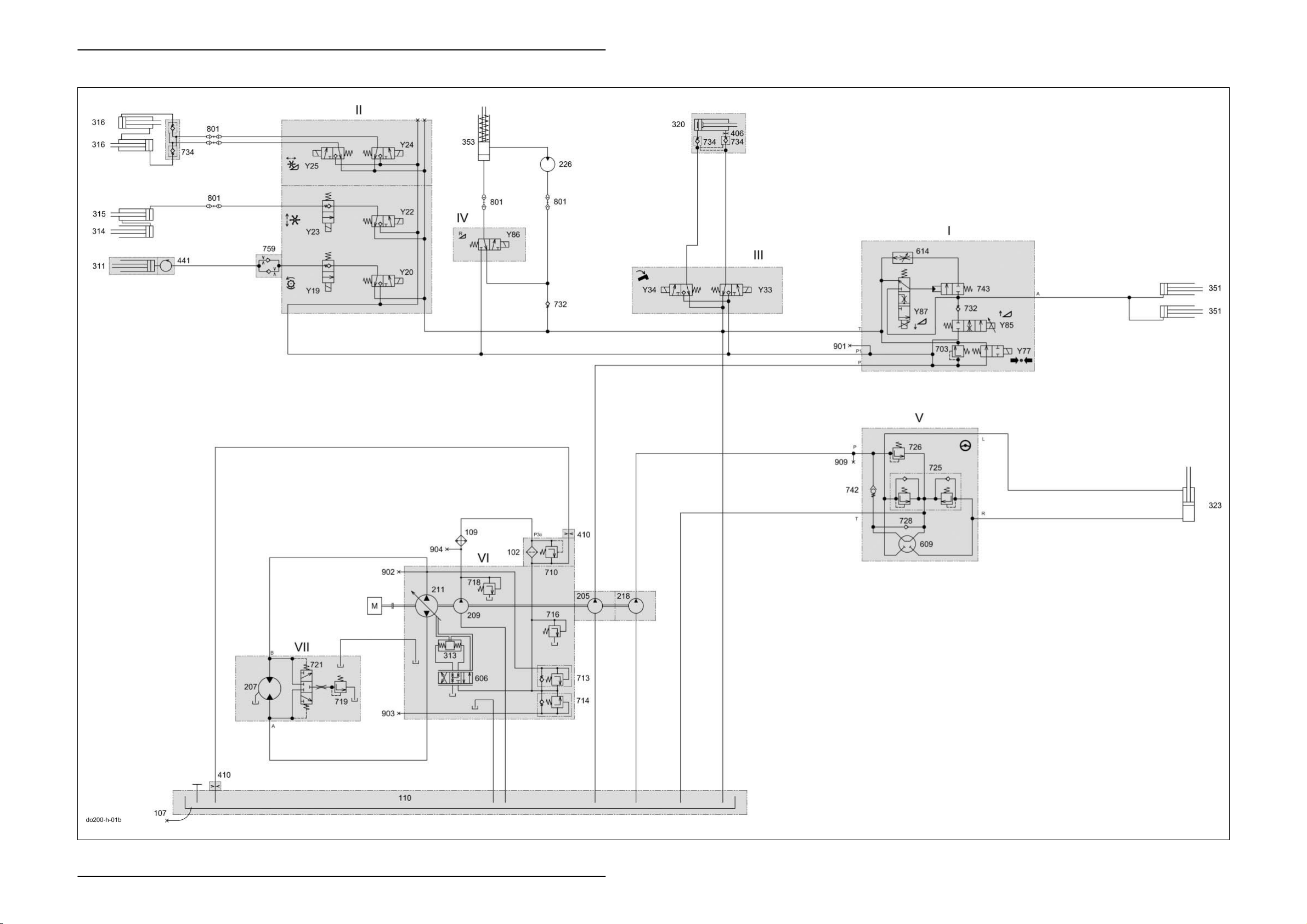
1.1 Overall hydraulic system circuit diagram with 3D sieve pan
1-4 DO-h-Kap1 04/04
Page 9

TIC Dominator 140 - 150 Overall Hydraulic System
Key to diagram:
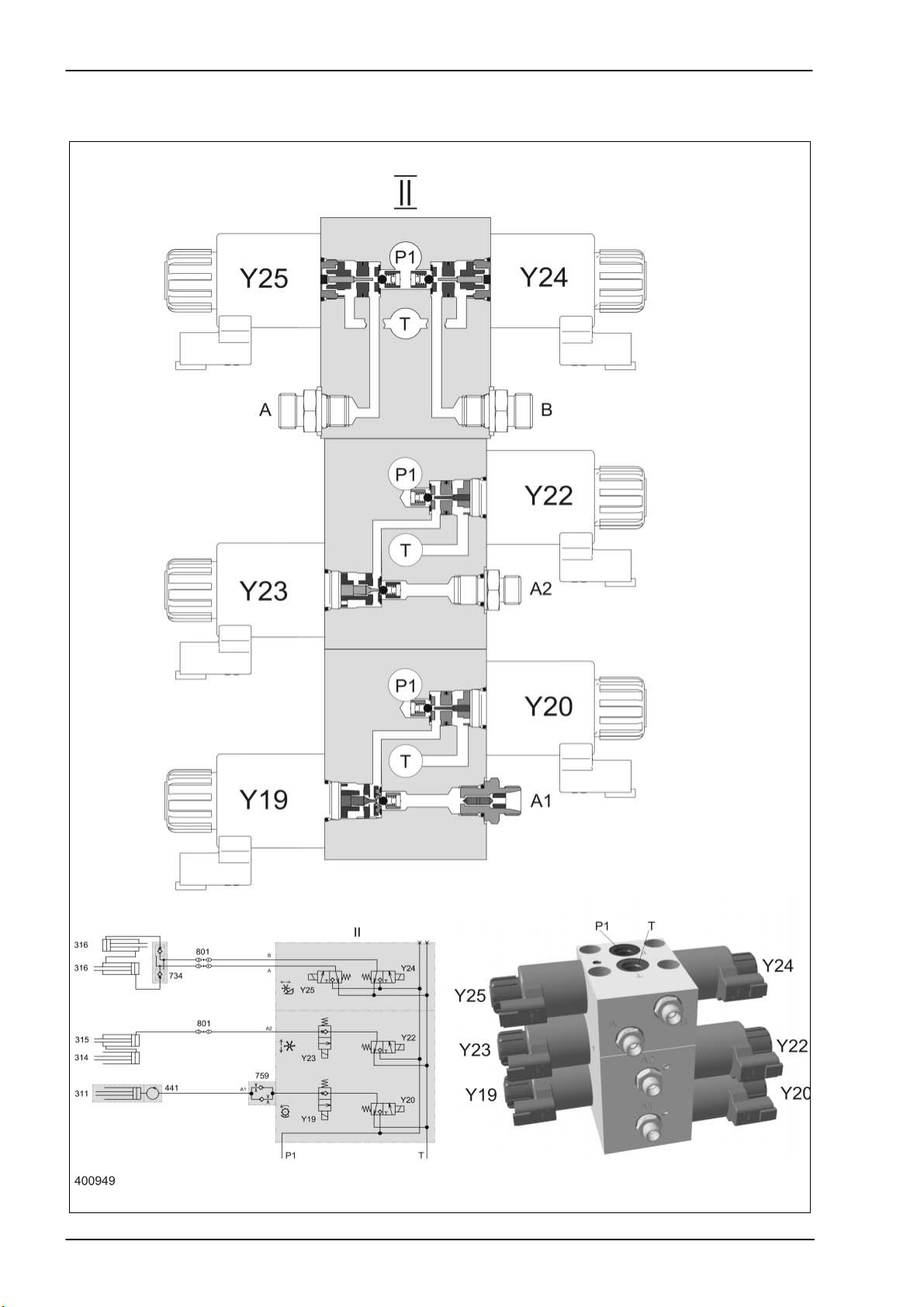
I Master valve working hydraulics valve block
II Front attachment / threshing drum variator working hydraulics
valve block
III Grain tank unloading tube working hydraulics valve block
IV Front attachment reverse working hydraulics valve block
V Orbitrol steering hydraulics
VI Ground drive hydraulics hydrostatic pump
VII Ground drive hydraulics hydrostatic motor
102 Pressure filter.......................................................... 10 µm
107 Oil drain
109 Oil cooler
110 Oil tank
112 Return filter
205 Working hydraulics pump ....................................... 10.8 cm
207 Ground drive fixed displacement motor HMF 75 .... 75 cm
209 Ground drive feed pump ......................................... 22.5 cm
211 Ground drive variable displacement pump
HPV 75 ......................................................... 75 cm
218 Steering hydraulics pump ....................................... 6 cm
3
/rev.
3
/rev.
3
/rev.
3
/rev.
3
/rev.
226 Front attachment reverser drive motor
301 3-D sieve pan hydraulic cylinder
311 Threshing drum variable-speed drive hydraulic cylinder
313 Ground drive servo control pump hydraulic cylinder
314 Reel raise/lower slave cylinder
315 Reel raise/lower main cylinder
316 Horizontal reel adjustment hydraulic cylinder
320 Swing grain tank unloading tube hydraulic cylinder
323 Steering hydraulic cylinder
351 Raise/lower front attachment hydraulic cylinder
353 Reverse front attachment hydraulic cylinder
406 Orifice plate............................................................. Ø 0.8 mm
410 Orifice plate ............................................................ Ø 1.5 mm
441 Rotary coupling
601 3D sieve pan pendulum control 4/3 way valve
606 Ground drive servo control 4/3 way valve
609 Orbitrol steering system rotary valve
614 Front attachment lower flow control valve
04/04 DO-h-Kap1 1-5
Page 10

Overall Hydraulic System Dominator 140 - 150 TIC
10
Key to diagram:
703 Working hydraulics pressure relief valve................ 180
710 Ground drive filter bypass valve ............................. 2 bar
+
713 Ground drive multi-function valve, reverse ............. 420 bar
714 Ground drive multi-function valve, forward ............. 420 bar
716 Ground drive feed pressure relief valve.................. 19 bar
718 Ground drive feed circuit cold start injector ............ 25 bar
719 Ground drive flush pressure control valve.............. 10 bar
721 Ground drive flush-out shuttle valve
725 Steering double shock valve................................... 150
726 Steering pressure relief valve ................................. 90
+5
+15
bar
bar
728 Anti-cavitation valve (non-return valve)
732 Non-return valve
734 Lock-up valve unit (non-return valve)
742 Steering safety valve
743 Front attachment lower valve
759 One-way restrictor valve, two-sided
801 Quick release coupling
901 Working hydraulics measuring point
902 Ground drive hydraulics high pressure backward measuring
point
903 Ground drive hydraulics high pressure forward measuring
point
904 Ground drive hydraulics feed pressure measuring point
909 Steering hydraulics measuring point
Y19 Threshing drum variable-speed drive slow solenoid valve
Y20 Threshing drum variable-speed drive fast solenoid valve
Y22 Reel raise solenoid valve
Y23 Reel lower solenoid valve
Y24 Reel forward solenoid valve
Y25 Reel reverse solenoid valve
Y33 Grain tank unloading tube swing out solenoid valve
Y34 Grain tank unloading tube swing in solenoid valve
Y77 Working hydraulics master valve solenoid valve
Y85 Raise front attachment solenoid valve
Y86 Reverse front attachment solenoid valve
Y87 Lower front attachment solenoid valve
1-6 DO-h-Kap1 04/04
Page 11

1.2
Overall hydraulic system
circuit diagram
without 3D sieve pan
Page 12
Overall Hydraulic System Dominator 140 - 150 TIC
1.2 Overall hydraulic system circuit diagram without 3D sieve pan
1-8 DO-h-Kap1 04/04
Page 13

TIC Dominator 140 - 150 Overall Hydraulic System
Key to diagram:
I Master valve working hydraulics valve block
II Front attachment / threshing drum variator working hydraulics
valve block
III Grain tank unloading tube working hydraulics valve block
IV Front attachment reverse working hydraulics valve block
V Orbitrol steering hydraulics
VI Ground drive hydraulics hydrostatic pump
VII Ground drive hydraulics hydrostatic motor
102 Pressure filter........................................................ 10 µm
107 Oil drain
109 Oil cooler
110 Oil tank
112 Return filter
205 Working hydraulics pump ..................................... 10.8 cm
207 Ground drive fixed displacement motor HMF 75 .. 75 cm
209 Ground drive feed pump ....................................... 22.5 cm
211 Ground drive variable displacement pump
HPV 75 ....................................................... 75 cm
218 Steering hydraulics pump ..................................... 6 cm
3
/rev.
3
/rev.
3
/rev.
3
/rev.
3
/rev.
226 Front attachment reverser drive motor
311 Threshing drum variable-speed drive hydraulic cylinder
313 Ground drive servo control pump hydraulic cylinder
314 Reel raise/lower slave cylinder
315 Reel raise/lower main cylinder
316 Horizontal reel adjustment hydraulic cylinder
320 Swing grain tank unloading tube hydraulic cylinder
323 Steering hydraulic cylinder
351 Raise/lower front attachment hydraulic cylinder
353 Reverse front attachment hydraulic cylinder
406 Orifice plate........................................................... Ø 0.8 mm
410 Orifice plate .......................................................... Ø 1.5 mm
441 Rotary coupling
606 Ground drive servo control 4/3 way valve
609 Orbitrol steering system rotary valve
614 Front attachment lower flow control valve
04/04 DO-h-Kap1 1-9
Page 14

Overall Hydraulic System Dominator 140 - 150 TIC
10
Key to diagram:
703 Working hydraulics pressure relief valve ...............180
710 Ground drive filter bypass valve ............................2 bar
+
713 Ground drive multi-function valve, reverse ............420 bar
714 Ground drive multi-function valve, forward ............420 bar
716 Ground drive feed pressure relief valve.................19 bar
718 Ground drive feed circuit cold start injector ...........25 bar
719 Ground drive flush pressure control valve.............10 bar
721 Ground drive flush-out shuttle valve
725 Steering double shock valve..................................150
726 Steering pressure relief valve ................................90
+5
+15
bar
bar
728 Anti-cavitation valve (non-return valve)
732 Non-return valve
734 Lock-up valve unit (non-return valve)
742 Steering safety valve
743 Front attachment lower valve
759 One-way restrictor valve, two-sided
801 Quick release coupling
901 Working hydraulics measuring point
902 Ground drive hydraulics high pressure backward measuring
point
903 Ground drive hydraulics high pressure forward measuring
point
904 Ground drive hydraulics feed pressure measuring point
909 Steering hydraulics measuring point
Y19 Threshing drum variable-speed drive slow solenoid valve
Y20 Threshing drum variable-speed drive fast solenoid valve
Y22 Reel raise solenoid valve
Y23 Reel lower solenoid valve
Y24 Reel forward solenoid valve
Y25 Reel reverse solenoid valve
Y33 Grain tank unloading tube swing out solenoid valve
Y34 Grain tank unloading tube swing in solenoid valve
Y77 Working hydraulics master valve solenoid valve
Y85 Raise front attachment solenoid valve
Y86 Reverse front attachment solenoid valve
Y87 Lower front attachment solenoid valve
1-10 DO-h-Kap1 04/04
Page 15

TIC Dominator 140 - 150 Overall Hydraulic System
1.3 Technical data
Working hydraulics Dominator 140 -150 Sense of rotation = Counterclockwise
Drive n
Power = 33 l/min at 10.8 cm3/rev.
max
= 3092 rpm
Steering hydraulics Dominator 140 -150 Sense of rotation = Counterclockwise
Drive n
Power = 18.5 l/min at 6 cm3/rev.
max
= 3092 rpm
Linde ground drive Dominator 140 -150 Sense of rotation = Counterclockwise
Drive n
Power approx. = 230 l/min at 75 cm3/rev.
max
= 3092 rpm
Linde feed pump Dominator 140 -150 Sense of rotation = Counterclockwise
Drive n
max
= 3092 rpm
Power = 69.5 l/min at 22.5 cm3/rev.
Note: The exact pump output can only be determined using a flowmeter.
During this measurement, the output under maximum system
pressure and at operating temperature (60°C) may fall by
15% max.
04/04 DO-h-Kap1 1-11
Page 16

Overall Hydraulic System Dominator 140 - 150 TIC
1-12 DO-h-Kap1 04/04
Page 17

TIC Dominator 140 - 150 Hydraulic System
Chapter 2
Steering
hydraulics
2.1 Steering hydraulics circuit diagram.......................................... 2-4
2.2 Steering valve unit ................................................................... 2-6
2.3 Function of steering ................................................................. 2-8
2.4 Checking the steering ............................................................ 2-12
04/04 DO-h-Kap2 2-1
Page 18

Hydraulic System Dominator 140 - 150 TIC
2-2 DO-h-Kap2 04/04
Page 19

2.1
Steering hydraulics circuit diagram
Page 20
Hydraulic System Dominator 140 - 150 TIC
2.1 Steering hydraulics circuit diagram
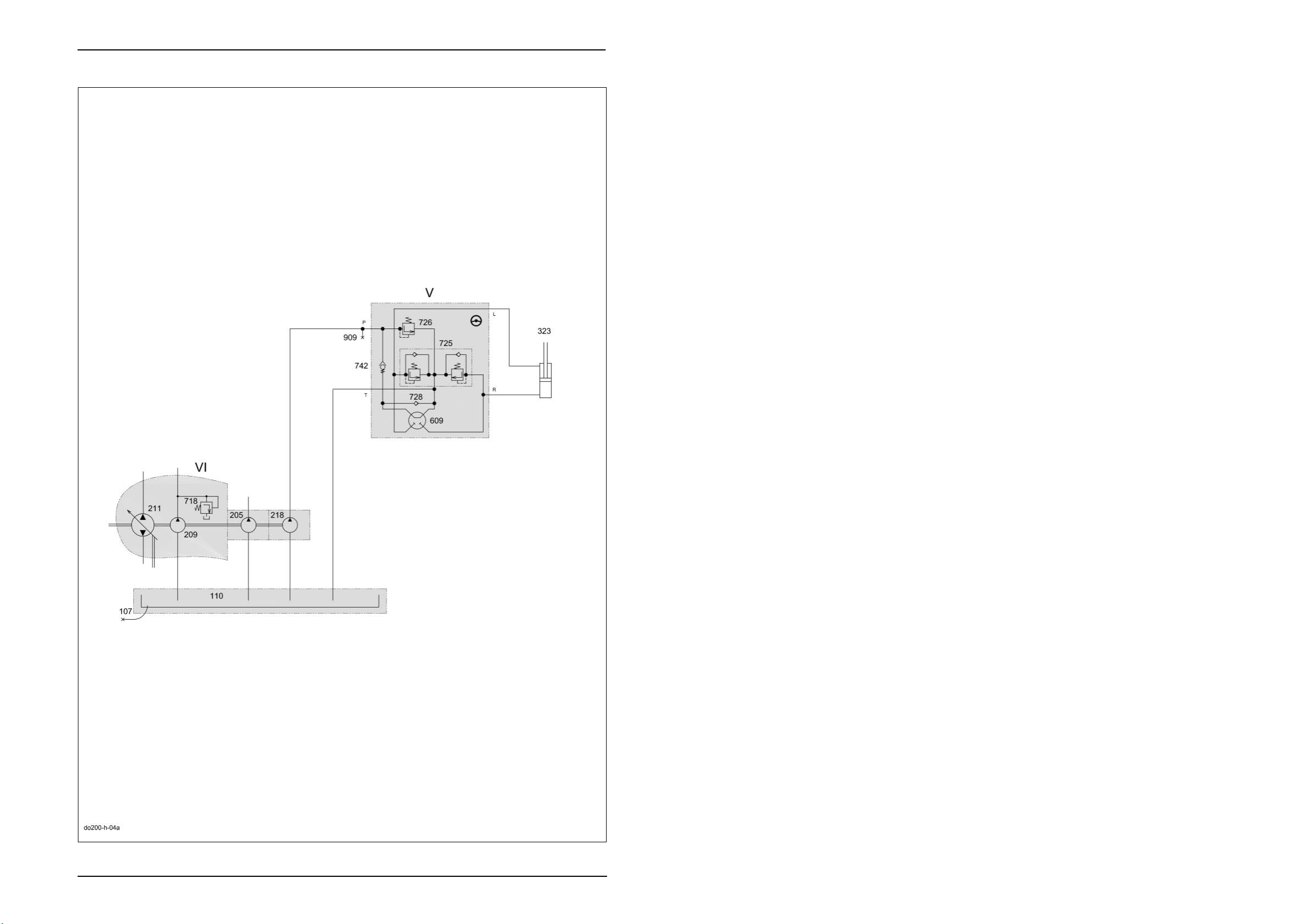
Key to diagram:
V Orbitrol steering hydraulics
VI Ground drive hydraulics hydrostatic pump
107 Oil drain
110 Oil tank
205 Working hydraulics pump
209 Ground drive feed pump
211 Ground drive variable displacement pump
218 Steering hydraulics pump
323 Steering hydraulic cylinder
609 Orbitrol steering system rotary valve
718 Ground drive feed circuit cold start injector...................... 25 bar
725 Steering double shock valve ...................................... 150
726 Steering pressure relief valve......................................... 90
+15
+5
bar
bar
728 Anti-cavitation valve (non-return valve)
742 Steering safety valve
909 Steering hydraulics measuring point
Pressure measurement :
Neutral circulation pressure = < 20 bar
System pressure = 90
Shock valve = 150
+15
+5
bar
bar
Note: These values refer to measurements made at the max. no-load
speed of the diesel engine and a hydraulic oil operating
temperature of approx. 60°C.
2-4 DO-h-Kap2 04/04
Page 21

TIC Dominator 140 - 150 Hydraulic System
Description of function:
Steering In the neutral steering position, oil flows freely through the
Turning the steering wheel to one direction causes the spools to rotate
At a rotation of 1.5°, the channels to the chambers start opening.
At 4°, the neutral position channels are completely closed.
At 6°, the channels to the chambers are fully open.
The rotation of the spools relative to each other is limited to ± 8°.
Rotation of rotor: Feed of an oil quantity which is proportional to the
steering control unit = Orbitrol (609).
relative to each other.
A feed of pressurized oil to the rotor set has the following effects:
rotation into the steering cylinder, the rear wheels being influenced. An
internal mechanical return from the rotor to the outside spool so that the
channels in the valve are closed when the rotor rotates to the same angle
as the steering wheel.
04/04 DO-h-Kap2 2-5
Page 22

Hydraulic System Dominator 140 - 150 TIC
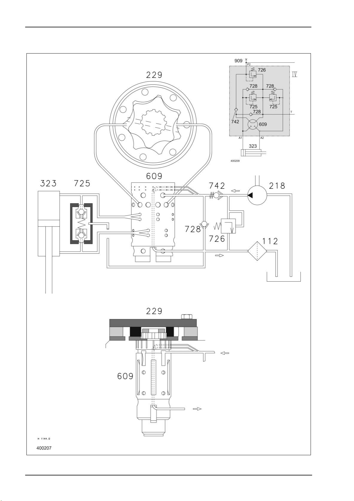
2.2 Steering valve unit
2-6 DO-h-Kap2 04/04
Page 23

TIC Dominator 140 - 150 Hydraulic System
Key to diagram:
112 Return filter (not installed)
218 Steering hydraulics pump ...........................................6 cm
3
229 Steering hydraulics proportioning pump
323 Steering hydraulic cylinder
609 Orbitrol steering system rotary valve
725 Steering double shock valve....................................... 150
726 Steering pressure relief valve ..................................... 90
+5
+15
bar
bar
728 Anti-cavitation valve (non-return valve)
742 Steering safety valve
909 Steering hydraulics measuring point
Steering system
Open center: with the steering in neutral position, there is a connection
between pump P2 and the tank.
Non reaction: when the steering is in neutral position, a force acting on
the steered wheels does not cause any reaction on the
steering wheel.
Valve unit
DANFOSS OSPB 125
O = Orbit (Orbitrol)
S = Steering
P = Pump
B = Version
125 = Oil displacement in cm
3
/rev.
Design of valve unit
The steering valve consists of a steering hydraulics proportioning pump
(229) and an Orbitrol rotary valve (609).
The Orbitrol rotary valve (609) is actuated by the steering gear shaft.
Continued rotary movement of the steering gear shaft drive the steering
hydraulics proportioning pump (229) by means of a socket-type shaft.
04/04 DO-h-Kap2 2-7
Page 24
Hydraulic System Dominator 140 - 150 TIC
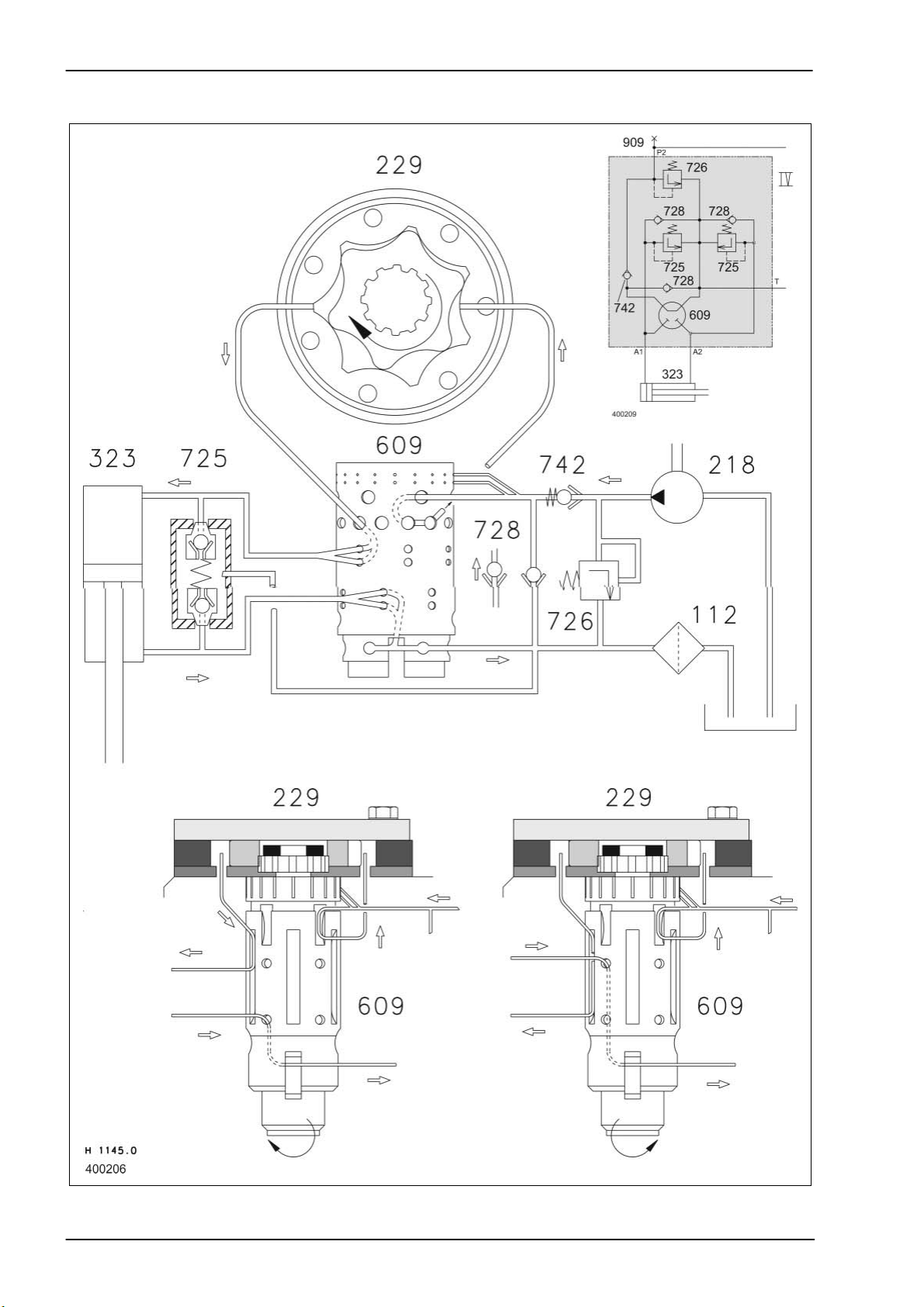
2.3 Function of steering
Neutral
2-8 DO-h-Kap2 04/04
Page 25

TIC Dominator 140 - 150 Hydraulic System
Description of function:
Neutral In neutral position, the oil is directed back to the tank via the steering
safety valve (742) and the Orbitrol rotary disc (609) (open center).
The circulation pressure must not exceed 20 bar.
Both sides of the steering hydraulic cylinder (323) are shut off by the
Orbitrol rotary disc (609). Pressure peaks due to external forces on the
steered axle are relieved to the tank via the steering double shock valves
(725) (non reaction).
04/04 DO-h-Kap2 2-9
Page 26
Hydraulic System Dominator 140 - 150 TIC
Steering actuation
2-10 DO-h-Kap2 04/04
Page 27

TIC Dominator 140 - 150 Hydraulic System
Description of function:
Steering actuation When actuating the steering to one or another direction, the Orbitrol rotary
disc (609) is rotated by up to 8° relative to the outside spool. During this
process, the return line from the steering hydraulics pump (218) to the
tank is closed and the connection to the steering hydraulics proportioning
pump (229) is released.
Via the steering hydraulics proportioning pump (229) and the Orbitrol
rotary disc (609), the volume flow is released as a function of the sense of
rotation, path and speed of steering wheel motion to the ram or the ram
ring surface of the steering hydraulic cylinder (323). Here, the displacing
surface of the steering hydraulic cylinder (323) is connected with the
return line to the tank via the Orbitrol rotary disc (609).
As soon as there is no more steering motion, leaf springs bring the outer
rotary disc of the Orbitrol rotary disc (609) back to neutral position. Now
both sides of the steering cylinder are shut off again and the connection
from the steering hydraulics pump (218) to the tank is re-established.
Emergency steering When the steering system is not supplied any more by the steering
hydraulics pump (218), the steering safety valve (742) closes and thus
ensures that no oil will escape from the steering system.
When the steering is actuated, the inner and outer disc of the Orbitrol
rotary disc (609) are rotated relative to each other. Now the oil can be
conveyed from one side of the steering hydraulic cylinder (323) via anticavitation valve (non-return valve) (728) to the other side through human
power by the drive of the steering hydraulics proportioning pump (229).
04/04 DO-h-Kap2 2-11
Page 28

Hydraulic System Dominator 140 - 150 TIC
2.4 Checking
the steering
Steering gear shaft Height play = 0.1 to 0.3 mm
Clearance from bottom inside rotary disc = 3 mm
Return When the steering wheel is actuated with the diesel engine shut off, the
leaf springs in the rotary disc must bring the steering wheel back to its
neutral position.
Reaction If steering reaction is insufficient, internal leaks in the steering system
must be checked. To do this, disconnect the lines from the steering
cylinder and plug them tightly with plugs.
With the oil at operating temperature and at max. no-load speed of the
diesel engine, the steering wheel must not allow more than 4 turns/minute
in both directions when using a force of approx. 25 Nm.
When the actual number of turns is more than 4/minute, check the
steering valve for leaks.
When the actual number of turns is below 4/minute, check the steering
cylinder for leaks.
Power In case of steering forces above 25 Nm, check tyre size and pressure,
condition of the cylinder rod and if stub axles move smoothly.
A pressure test at the steering hydraulics measuring port must show the
value 90
+5
bar.
To this end move the steering wheel up to the stop and hold it in this
position.
Adjusting the pressure relief valve on the machine in built-in condition is
not possible.
Important! Any installation work on the steering hydraulics must be
followed by venting the system on both hydraulic lines of the
steering cylinder with the diesel engine running.
2-12 DO-h-Kap2 04/04
Page 29

TIC Dominator 140 - 150 Hydraulic System
Chapter 3
Working
hydraulics
3.1
Working hydraulics circuit diagram .......................................... 3-4
3.2
Main valve................................................................................ 3-6
with master valve,
pressure relief valve,
raise/lower front attachment .................................................... 3-6
3.3
Threshing drum speed control
3/3 way solenoid valve Y19/Y20............................................ 3-12
Hydraulic cylinder with rotary coupling .................................. 3-14
3.4 Vertical reel adjustment ......................................................... 3-16
3/3 way valve Y22/Y23 .......................................................... 3-16
Hydraulic cylinders................................................................. 3-18
3.5
Horizontal reel adjustment ..................................................... 3-20
4/3 way valve Y24/Y25 .......................................................... 3-20
Hydraulic cylinders................................................................. 3-22
Lock-up valve unit (734) ........................................................ 3-24
3.6
Swinging the grain tank unloading tube................................. 3-26
4/3 way valve Y33/Y34 .......................................................... 3-26
Hydraulic cylinders................................................................. 3-28
Lock-up valve unit (734) ........................................................ 3-30
3.7 Reverse front attachment ...................................................... 3-32
3/2-way valve Y86.................................................................. 3-32
Hydraulic cylinders................................................................. 3-34
04/04 DO-h-Kap3 3-1
Page 30

Hydraulic System Dominator 140 - 150 TIC
3-2 DO-h-Kap2 04/04
Page 31

3.1
Working hydraulics circuit diagram
- without straw collector
Page 32

Hydraulic System Dominator 140 - 150 TIC
3.1 Working hydraulics circuit diagram
- without straw collector
Key to diagram:
I Master valve working hydraulics valve block
II Front attachment / threshing drum variator working hydraulics
valve block
III Grain tank unloading tube working hydraulics valve block
IV Front attachment reverse working hydraulics valve block
VI Ground drive hydraulics hydrostatic pump
107 Oil drain
110 Oil tank
112 Return filter
205 Working hydraulics pump ..................................... 10.8 cm
209 Ground drive feed pump ....................................... 22.5 cm
211 Ground drive variable displacement
pump HPV 75 ....................................................... 75 cm
218 Steering hydraulics pump ..................................... 6 cm
3
/rev.
3
/rev.
3
/rev.
3
/rev.
226 Front attachment reverser drive motor
311 Threshing drum variable-speed drive hydraulic cylinder
314 Reel raise/lower slave cylinder
315 Reel raise/lower master cylinder
316 Horizontal reel adjustment hydraulic cylinder
320 Swing grain tank unloading tube hydraulic cylinder
351 Raise/lower front attachment hydraulic cylinder
353 Reverse front attachment hydraulic cylinder
406 Orifice plate........................................................... Ø 0.8 mm
441 Rotary coupling
614 Front attachment lower flow control valve
703 Working hydraulics pressure relief valve .............. 180
+10
718 Ground drive feed circuit cold start injector .......... 25 bar
732 Non-return valve
734 Lock-up valve unit (non-return valve)
743 Front attachment lower valve
759 One-way restrictor valve, two-sided
801 Quick release coupling
901 Working hydraulics measuring point
Y19 Threshing drum variable-speed drive slow solenoid valve
Y20 Threshing drum variable-speed drive fast solenoid valve
Y22 Reel raise solenoid valve
Y23 Reel lower solenoid valve
Y24 Reel forward solenoid valve
Y25 Reel reverse solenoid valve
Y33 Grain tank unloading tube swing out solenoid valve
Y34 Grain tank unloading tube swing in solenoid valve
Y77 Working hydraulics master valve solenoid valve
Y85 Raise front attachment solenoid valve
Y86 Reverse front attachment solenoid valve
Y87 Lower front attachment solenoid valve
3-4 DO-h-Kap2 04/04
Page 33

TIC Dominator 140 - 150 Hydraulic System
Description of function:
The working hydraulics of the Dominator series is an open hydraulic
system.
The maximum system pressure is limited to 180
+10
bar by means of
pressure relief valve (703).
04/04 DO-h-Kap3 3-5
Page 34

Hydraulic System Dominator 140 - 150 TIC
3.2 Main valve with master valve, pressure relief valve, raise/lower front attachment
3-6 DO-h-Kap3 04/04
Page 35

TIC Dominator 140 - 150 Hydraulic System
Key to diagram:
614 Flow control valve ................................................5 - 50 l/min
703 Pressure relief valve ............................................180
732 Non-return valve (inlet valve)
743 Lower front attachment pilot valve
Y77 Master valve solenoid valve
Y85 Raise front attachment solenoid valve
Y87 Lower front attachment solenoid valve
A1 Raise/lower front attachment hydraulic cylinder
P1 Working hydraulics pump port
P2 Parallel port for working hydraulics of other directional control
valves
T Tank port
E Pilot spool
F Compression spring
H Front attachment raise spool
K Front attachment quick lower ram
L Lower front attachment spool
R Control spool........................................................5 - 50 l/min
U Master valve control spool
V Pilot valve
+10
bar
Description of function:
Pressure limitation The spring in the pressure relief valve (703) is pre-stressed for a system
A 0.5 mm shim corresponds to approx. 10 bar
Note: The above values refer to a rated pressure of 180 bar and may
pressure of 180
removing or adding shims.
A 1.2 mm shim corresponds to approx. 23 bar
+10
bar. The pressure setting may be modified by
deviate, depending on the actual system. Each time the setting
has been modified, the system pressure must be checked.
04/04 DO-h-Kap3 3-7
Page 36
Hydraulic System Dominator 140 - 150 TIC
Basic setting
To ensure the position of spool (H) for the function "Raise front
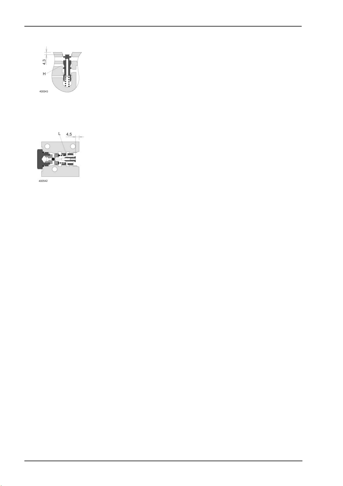
attachment", the dimension from the top edge of the spool (H) to the body
must be 4.3 mm with the coil core (Y85) removed. The position may be
corrected by removing or adding shims above the compression spring.
A weaker compressed spring - as compared to the spool (H) - is located
below the spool of the master valve (U).
In order to guarantee the "Front attachment lower" function, the clearance
between the top edge of spool (L) and the housing must be 4.5 mm with
the coil core (Y87) removed. The position may be corrected by removing
or adding shims.
Spare part no: 0.1 mm = 0218 886.0
0.2 mm = 0218 887.0
The drop rate of the front attachment can be adjusted to a drop time of
5-6 sec. over the entire stroke range.on the flow control valve (614).
3-8 DO-h-Kap3 04/04
Page 37

TIC Dominator 140 - 150 Hydraulic System
Key to diagram:
P Pump port
M Measuring port
R(T) Return line port (tank)
Description of function:
Pressure relief valve The pressure relief valve protects the hydraulic system and thus the
connected mechanical components from damage by excessive forces.
The spring in the pressure relief valve (703) is pre-stressed for a system
pressure of 180
+10
bar. The pressure setting may be modified by removing
or adding shims.
A 0.5 mm shim corresponds to approx. 10 bar
A 1.2 mm shim corresponds to approx. 23 bar
Note: The above values refer to a rated pressure of 180 bar and may
deviate, depending on the actual system. Each time the setting
has been modified, the system pressure must be checked.
Note: These values refer to measurements made at the max. no-load
speed of the diesel engine and a hydraulic oil operating
temperature of approx. 60°C.
04/04 DO-h-Kap3 3-9
Page 38

Hydraulic System Dominator 140 - 150 TIC
Description of function:
Function of master valve The master valve (Y77) blocks the circulating volume flow from P to T of
the open hydraulic system when a working hydraulics function has been
actuated. Single-acting functions are an exception to this if the consumer
is relieved to the tank.
In neutral position, the master valve (Y77) is not actuated, making the oil
flow back to the tank via the ring channels on the spool (U). Due to the
large channel cross-section, the circulation pressure is very low.
When pressure is successfully built up at a consumer, the master valve
(Y77) is actuated simultaneously with the directional control valve of the
corresponding function. Now spool (U) closes the connection from P to T,
and the top ring channel being closed first in order to achieve smooth
switching-over.
The pressure relief valve (703) opens at a maximum system pressure of
180±10 bar and relieves the pressure to the tank.
Raise front attachment
function
Raising When the "Raise" function is used, the directional control valve (Y85) and
the master valve (Y77) are actuated with 12 V DC.
The spool (H) is moved to its end position, making oil flow via both ring
channels on the spool (H). The full volume flow is directed to the
consumer port (A1) via the non-return valve (732) and raises the front
attachment.
Lower front attachment
function
Lowering When the "Lower" function is used, only the directional control valve (Y87)
is actuated with 12 V DC.
The spherical seat in pilot valve (V) is opened and the spring force (F) is
overcome through the force of the solenoid. The spool (E) closes the ring
channel to the return line, making the load pressure of the front
attachment act on the ram top side (K) and open the pilot valve (743). The
oil is now displaced by the front attachment via the pilot valve (743) and
the control spool (R) into the return line to the tank.
3-10 DO-h-Kap3 04/04
Page 39

TIC Dominator 140 - 150 Hydraulic System
Description of function:
Flow control valve When the "Lower front attachment – fast" function is used, the oil
displaced via port A flows to the tank (T) through the restrictor in the
control spool of the flow control valve (614).
This creates a ram pressure ahead of the control spool, making the latter
move against the control spring and restrict the return channel to the tank
(T) as a function of the load pressure.
When the load pressure in port A changes, both the volume flow through
the restrictor and the load pressure against the control spool change, too,
and consequently also the return channel cross-section.
This control function keeps the volume flow and therefore the front
attachment drop rate constant, independent of the load pressure.
The front attachment drop rate is adjusted merely by the pre-stress of the
control spring at the handwheel.
Relieve tension of control spring = lower drop rate
Tensioning the control spring = increase drop rate
04/04 DO-h-Kap3 3-11
Page 40
Hydraulic System Dominator 140 - 150 TIC
3.3 Threshing drum speed control 3/3 way solenoid valve Y19/Y20
3-12 DO-h-Kap3 04/04
Page 41

TIC Dominator 140 - 150 Hydraulic System
Key to diagram:
Description of function:
Neutral function The threshing drum variable-speed drive hydraulic cylinder (311) is tightly
Increase speed function The threshing drum fast solenoid valve (Y20) and the master valve are
Reduce speed function Solenoid valve (Y19) is actuated without the master valve. The pilot spool
Note: To ensure even control function in both directions, volume flow
II Front attachment / threshing drum variator working hydraulics
valve block
311 Threshing drum variable-speed drive hydraulic cylinder
314 Reel raise/lower slave cylinder
315 Reel raise/lower master cylinder
316 Horizontal reel adjustment hydraulic cylinder
441 Rotary coupling
759 One-way restrictor valve, two-sided
801 Quick release coupling
Y19 Threshing drum variable-speed drive slow solenoid valve
Y20 Threshing drum variable-speed drive fast solenoid valve
Y22 Reel raise solenoid valve
Y23 Reel lower solenoid valve
Y24 Reel forward solenoid valve
Y25 Reel reverse solenoid valve
closed by the ball seat in the valve insert of the threshing drum slow
solenoid valve (Y19).
actuated at the same time. The corresponding pilot spool opens the ball in
the valve insert and closes the return line to the tank. The pressure thus
rising opens the ball in the valve insert of the unactuated threshing drum
slow solenoid valve (Y19). The oil flows to consumer port A1 via the notch
in the one-way restrictor valve (759).
in question opens the ball in the valve insert and thus relieves the oil
pressure via the notch of the one-way restrictor valve (759) and the valve
insert of the unactuated threshing drum fast solenoid valve (Y20) to the
tank.
flows via the notches in the one-way restrictor valve (759) when
adjusting the variator.
04/04 DO-h-Kap3 3-13
Page 42

Hydraulic System Dominator 140 - 150 TIC
Threshing drum speed control
Hydraulic cylinder with rotary coupling
3-14 DO-h-Kap3 04/04
Page 43

TIC Dominator 140 - 150 Hydraulic System
Key to diagram:
311 Threshing drum variable-speed drive hydraulic cylinder
441 Rotary coupling
04/04 DO-h-Kap3 3-15
Page 44

Hydraulic System Dominator 140 - 150 TIC
3.4 Vertical reel adjustment 3/3 way valve Y22/Y23
3-16 DO-h-Kap3 04/04
Page 45

TIC Dominator 140 - 150 Hydraulic System
Key to diagram:
Description of function:
Neutral The hydraulic cylinders are tightly closed by the valve insert of solenoid
Raise reel The solenoid valve (Y22) and the master valve (Y77) are actuated at the
Lower reel Solenoid valve (Y23) is actuated without the master valve (Y77). The pilot
II Front attachment / threshing drum variator working hydraulics
valve block
311 Threshing drum variable-speed drive hydraulic cylinder
314 Reel raise/lower slave cylinder
315 Reel raise/lower master cylinder
316 Horizontal reel adjustment hydraulic cylinder
441 Rotary coupling
759 One-way restrictor valve, two-sided
801 Quick release coupling
Y19 Threshing drum variable-speed drive slow solenoid valve
Y20 Threshing drum variable-speed drive fast solenoid valve
Y22 Reel raise solenoid valve
Y23 Reel lower solenoid valve
Y24 Reel forward solenoid valve
Y25 Reel reverse solenoid valve
valve (Y23).
same time. The corresponding pilot spool opens the ball in the valve
insert and closes the return line to the tank.
The pressure P1 which consequently rises opens the valve insert of the
unactuated solenoid valve (Y23) and the oil flows to the consumer
port A2.
spool in question opens the ball in the valve insert and thus relieves the
oil pressure to the tank via the valve insert of the unactuated solenoid
valve (Y22).
04/04 DO-h-Kap3 3-17
Page 46
Hydraulic System Dominator 140 - 150 TIC
Vertical reel adjustment
Hydraulic cylinders
3-18 DO-h-Kap3 04/04
Page 47

TIC Dominator 140 - 150 Hydraulic System
Key to diagram:
Description of function:
Bottom valves The bottom outlet valves (V) in master cylinder (315) are opened upon
Note: For repairs, it is recommended to remove the hydraulic rams in
314 Reel raise/lower slave cylinder
315 Reel raise/lower master cylinder
A3 Hydraulic cylinder port
E Vent plug
V Bottom valves
reaching the upper stop position so that the slave cylinder can be filled
and vented.
the raised reel position since the slave cylinder is filled only with
the master cylinder fully extended. During this process support
and secure the reel properly.
04/04 DO-h-Kap3 3-19
Page 48

Hydraulic System Dominator 140 - 150 TIC
3.5 Horizontal reel adjustment 4/3 way valve Y24/Y25
3-20 DO-h-Kap3 04/04
Page 49

TIC Dominator 140 - 150 Hydraulic System
Key to diagram:
Description of function:
Neutral Both sides of the hydraulic cylinder are tightly closed by the lock-up valve
Reel forward / reverse Depending on the necessary direction of movement, one of the solenoid
The return line of the hydraulic cylinder is relieved to the tank via the valve
II Front attachment / threshing drum variator working hydraulics
valve block
311 Threshing drum variable-speed drive hydraulic cylinder
314 Reel raise/lower slave cylinder
315 Reel raise/lower master cylinder
316 Horizontal reel adjustment hydraulic cylinder
441 Rotary coupling
759 One-way restrictor valve, two-sided
801 Quick release coupling
Y19 Threshing drum variable-speed drive slow solenoid valve
Y20 Threshing drum variable-speed drive fast solenoid valve
Y22 Reel raise solenoid valve
Y23 Reel lower solenoid valve
Y24 Reel forward solenoid valve
Y25 Reel reverse solenoid valve
unit (734).
valves (Y24/Y25) and, at the same time, the master valve (Y77) is
actuated. The corresponding pilot spool opens the ball in the valve insert
and closes the return line to the tank. The pressure which consequently
rises builds up against the ram in lock-up valve unit (734) and thus
unlocks the return line to the tank in the opposite port.
insert of the unactuated solenoid valve (Y24/Y25). The pressure rising
further now opens the lock-up valve unit (734) on the pressure side and
the hydraulic cylinders are retracted or extended.
04/04 DO-h-Kap3 3-21
Page 50

Hydraulic System Dominator 140 - 150 TIC
Horizontal reel adjustment
Hydraulic cylinders
3-22 DO-h-Kap3 04/04
Page 51

TIC Dominator 140 - 150 Hydraulic System
Key to diagram:
Description of function:
Bottom valves The bottom outlet valves (V) open every time an end position is reached
316 Horizontal reel adjustment hydraulic cylinder
A2 Hydraulic cylinder port
A3 Hydraulic cylinder port
V Bottom valves
so that air inclusions in the connection between the two rams can be
flushed out.
After a repair, the cylinders must be flushed in both end positions for
approx. 15 sec.
04/04 DO-h-Kap3 3-23
Page 52

Hydraulic System Dominator 140 - 150 TIC
Horizontal reel adjustment
Lock-up valve unit (734)
3-24 DO-h-Kap3 04/04
Page 53

TIC Dominator 140 - 150 Hydraulic System
Key to diagram:
Description of function:
Lock-up valve units (pilot controlled non-return valves) are used in order
A rising pressure in port (B) moves the internal ram (K). This opens the
The continued pressure increase now opens the non-return valve in
A Hydraulic valve port
B Hydraulic valve port
A1 Consumer port
B1 Consumer port
to lock functions while pressure is relieved and thus to ensure a fixed
position of a consumer.
opposite non-return valve in port A - the return line of the hydraulic
cylinder to the tank is relieved (connection A-A1).
port B. The connection to consumer (B-B1) is relieved.
04/04 DO-h-Kap3 3-25
Page 54
Hydraulic System Dominator 140 - 150 TIC
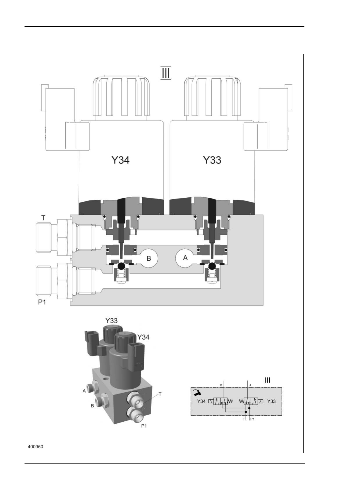
3.6 Swinging the grain tank unloading tube 4/3 way valve Y33/Y34
3-26 DO-h-Kap3 04/04
Page 55

TIC Dominator 140 - 150 Hydraulic System
Key to diagram:
Description of function:
Neutral function Both sides of the hydraulic cylinder (320) are tightly closed by the non-
Description of function Depending on the necessary direction of movement, one of the solenoid
The pressure which consequently rises builds up against the ram in lock-
The return line of the hydraulic cylinder is relieved to the tank via the valve
III Grain tank unloading tube working hydraulics valve block
Y33 Grain tank unloading tube swing out solenoid valve
Y34 Grain tank unloading tube swing in solenoid valve
A Consumer port
B Consumer port
P1 Working hydraulics pump port
T Tank port
return valves (734).
valves (Y33/Y34) and, at the same time, the master valve (Y77) is
actuated. The corresponding pilot spool opens the ball in the valve insert
and closes the return line to the tank.
up valve unit (734) of the swing grain tank unloading tube hydraulic
cylinder (320) and in this process opens port A and/or B.
insert of the unactuated solenoid valve (Y34/Y33). The pressure rising
further now opens the non-return valve (lock-up valve unit 734) at the
opposite port B and/or A and the hydraulic cylinder is retracted or
extended.
04/04 DO-h-Kap3 3-27
Page 56

Hydraulic System Dominator 140 - 150 TIC
Swinging the grain tank unloading tube
Hydraulic cylinders
3-28 DO-h-Kap3 04/04
Page 57

TIC Dominator 140 - 150 Hydraulic System
Key to diagram:
320 Swing grain tank unloading tube hydraulic cylinder
S Securing wire
K Ram thread glued with liquid locking compound
04/04 DO-h-Kap3 3-29
Page 58

Hydraulic System Dominator 140 - 150 TIC
Swinging the grain tank unloading tube
Lock-up valve unit (734)
3-30 DO-h-Kap3 04/04
Page 59

TIC Dominator 140 - 150 Hydraulic System
r
Key to diagram:
Description of function:
Lock-up valve units (pilot controlled non-return valves) are used in order to
A rising pressure in port (B) moves the internal ram (K). This opens the
The continued pressure increase now opens the non-return valve in port
A Hydraulic valve port
B Hydraulic valve port
A1 Consumer port
B1 Consumer port
lock functions while pressure is relieved and thus to ensure a fixed position
of a consumer.
opposite non-return valve in port A - the return line of the hydraulic cylinde
to the tank is relieved (connection A-A1).
B. The connection to consumer (B-B1) is relieved.
04/04 DO-h-Kap3 3-31
Page 60
Hydraulic System Dominator 140 - 150 TIC
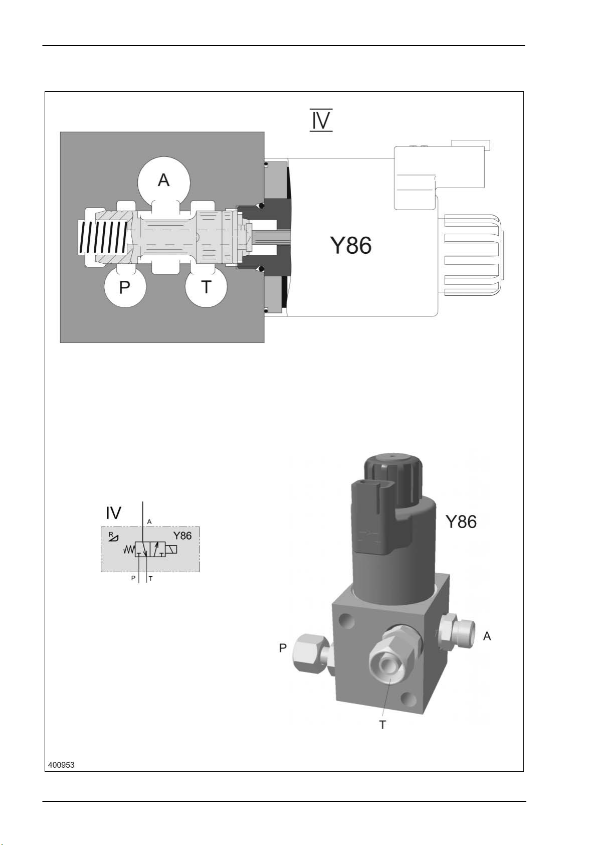
3.7 Reverse front attachment
3/2-way valve Y86
3-32 DO-h-Kap3 04/04
Page 61

TIC Dominator 140 - 150 Hydraulic System
Key to diagram:
Description of function:
Neutral The spring force displaces the oil from the reversing cylinder (353) via the
Reversing The solenoid valve (Y86) and the master valve (Y77) are actuated. The
IV Front attachment reverse valve block
Y86 Reverse front attachment solenoid valve
A Consumer port
P1 Working hydraulics pump port
T Tank port
connection A-T in the solenoid valve (Y86) to the tank. During this
process, port P1 is closed by the spool.
return line to the tank is now closed by the spool in solenoid valve (Y86)
and the connection from P to the consumer port A is established. The
reversing cylinder (353) now extends and swings the hydraulic motor
(226) to the drive gearwheel. Just before reaching its end position, the oil
flow from the reversing cylinder (353) to the hydraulic motor (226) is
released, ensuring reliable gearwheel engaging. The non-return valve
(732) keeps the hydraulic motor (226) from starting when pressure peaks
occur in the return line.
04/04 DO-h-Kap3 3-33
Page 62

Hydraulic System Dominator 140 - 150 TIC
Reverse front attachment
Hydraulic cylinders
3-34 DO-h-Kap3 04/04
Page 63
TIC Dominator 140 - 150 Hydraulic System
Key to diagram:
Description of function:
Reversing When the solenoid valve (Y86) is actuated, the reversing cylinder (353)
The non-return valve (732) keeps the hydraulic motor (226) from starting
Adjustment The reverser support is aligned towards the feed rake conveyor drive
The piston stroke is adjusted using the set screw (E). With the reverser
Installation position of
reverser motor OMP 200
353 Reverse front attachment hydraulic cylinder
extends and swings the hydraulic motor (226) to the drive gearwheel. Just
before reaching its end position, the oil flow from the reversing cylinder
(353) to the hydraulic motor (226) is released. This ensures reliable
engaging of the gearwheels for the reversing process.
when pressure peaks occur in the return line.
shaft by adjusting an eccentric bushing on the reverser cylinder (353).
swung in, the set screw (E) must have a play of 0.5 mm from the end
stop, then jam the set screw (E).
04/04 DO-h-Kap3 3-35
Page 64

Hydraulic System Dominator 140 - 150 TIC
3-36 DO-h-Kap3 04/04
Page 65

TIC Dominator 140 - 150 Hydraulic System
Chapter 4
Ground drive
hydraulics
4.1
LINDE ground drive hydraulics circuit diagram ....................... 4-4
4.2 Pump unit................................................................................. 4-8
4.3 Servo control valve ................................................................ 4-10
4.4 Ground drive multi-function valve .......................................... 4-12
4.5 Ground drive fixed displacement motor................................. 4-14
4.6 Maintenance .......................................................................... 4-17
4.7 3D cleaning system................................................................ 4-18
04/04 DO-h-Kap4 4-1
Page 66

Hydraulic System Dominator 140 - 150 TIC
4-2 DO-h-Kap4 04/04
Page 67

4.1
LINDE ground drive hydraulics circuit diagram
Page 68
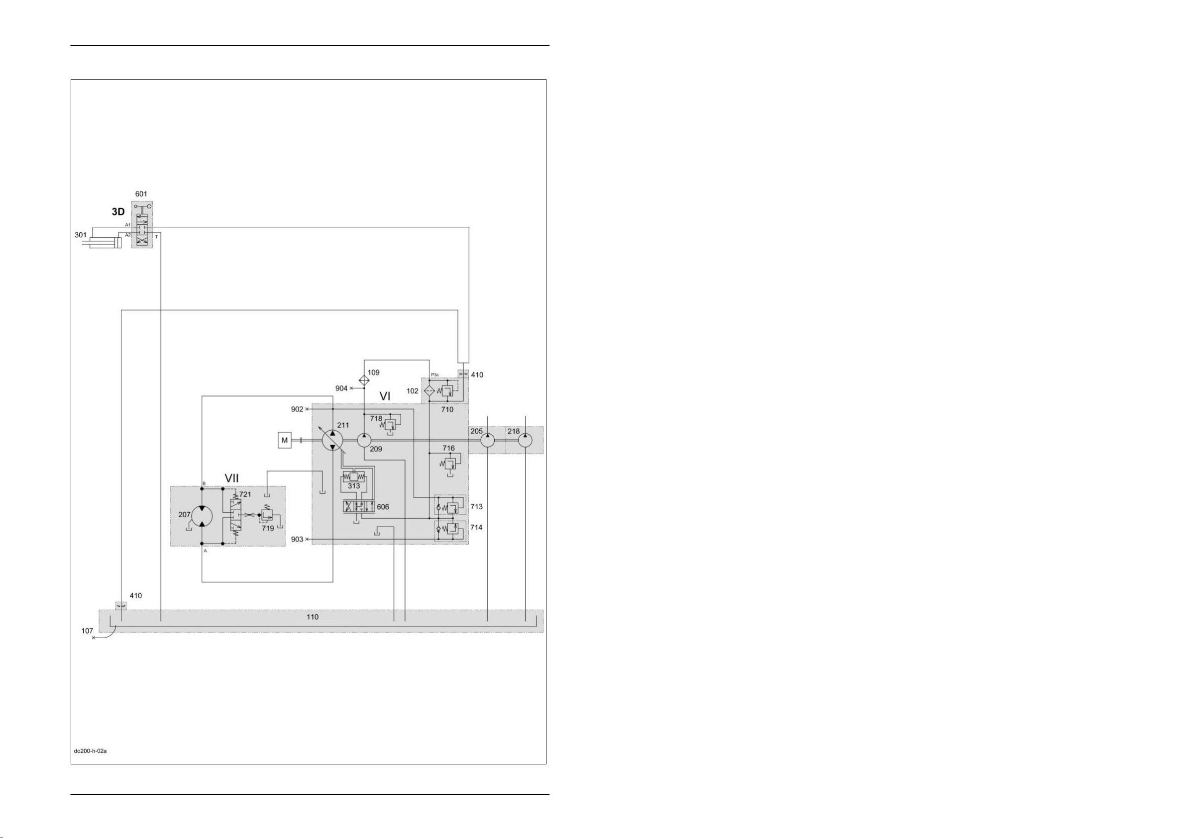
Hydraulic System Dominator 140 - 150 TIC
4.1 LINDE ground drive hydraulics circuit diagram
Key to diagram:
VI Ground drive hydraulics hydrostatic pump
VII Ground drive hydraulics hydrostatic motor
102 Pressure filter.............................................................. 10 µm
107 Oil drain
109 Oil cooler
110 Oil tank
205 Working hydraulics pump ........................................... 10.8 cm
207 Ground drive fixed displacement motor HMF 75........ 75 cm
209 Ground drive feed pump............................................. 22.5 cm
211 Ground drive variable displacement pump HPV 75 ... 75 cm
218 Steering hydraulics pump ........................................... 6 cm
3
/rev.
3
/rev.
3
/rev.
3
/rev.
3
/rev.
301 3-D sieve pan hydraulic cylinder
313 Ground drive servo control pump hydraulic cylinder
410 Orifice plate ................................................................ Ø 1.5 mm
601 3D sieve pan pendulum control 4/3 way valve
606 Ground drive servo control 4/3 way valve
710 Ground drive filter bypass valve ................................. 2 bar
713 Ground drive multi-function valve, reverse................. 420 bar
714 Ground drive multi-function valve, forward................. 420 bar
716 Ground drive feed pressure relief valve...................... 19 bar
718 Ground drive feed circuit cold start injector ................ 25 bar
719 Ground drive flush pressure control valve.................. 10 bar
721 Ground drive flush-out shuttle valve
902 Ground drive hydraulics high pressure backward measuring point
903 Ground drive hydraulics high pressure forward measuring point
904 Ground drive hydraulics feed pressure measuring point
4-4 DO-h-Kap4 04/04
Page 69

TIC Dominator 140 - 150 Hydraulic System
Description of function:
Oil supply After starting the diesel engine, the ground drive feed pump (209) is
driven.
In this process, the oil quantity is taken from the housing. The housing is
directly connected with the oil tank (110).
Feed pressure circuit The feed pressure builds up from the oil quantity pumped through the oil
cooler (109) and the pressure filter (102) by the ground drive feed pump
(209) against the ground drive feed pressure relief valve (716).
Depending on the spring setting, the oil flow is pre-stressed and then
relieved to the tank.
The feed pressure is applied at the combined ground drive multi-function
valves (713/714) and at both servo cylinders via the ground drive servo
adjustment valve (606).
When the ground drive variable displacement pump (211) is not swung
out, the feed pressure propagates to both sides of the high-pressure
circuit via ground drive multi-function valves (713/714).
Servo control The cable mounted on the ground speed control lever moves the spool in
the ground drive servo adjustment valve (606) from the neutral position to
one or the other direction.
Depending on the direction of travel, one of the ground drive pump servo
adjustment hydraulic cylinders (313) is pressure-relieved whereas the
other hydraulic cylinder remains connected to the feed pressure circuit.
The motion at the swing disc corresponds to the pressure difference
between the hydraulic cylinders.
The ground drive pump servo adjustment hydraulic cylinders (313) swing
the ground drive variable displacement pump (211) only by the path
defined by the ground speed control lever because there is a mechanical
feedback of the swing angle to the ground drive servo adjustment valve
(606).
This mechanical feedback balances the spool in the ground drive servo
adjustment valve (606) and therefore the pressure level between the two
hydraulic cylinders at the control edge so that the defined swing angle is
maintained.
High-pressure circuit As soon as the ground drive variable displacement pump (211) is swung
out, an axial motion is added to the radial motion of the pump unit.
This axial motion displaces the oil in the cylinder space of the rotor and
thus acts on the motor unit which converts this energy into a rotating
motion by supporting against the fixed inclined disc.
The respective suction side of the ground drive variable displacement
pump (211) is pre-stressed via the feed pressure circuit and the
corresponding ground drive multi-function valve (713/714). This ensures
that the ground drive variable displacement pump (211) is sufficiently filled
and that any occurring leaks are compensated.
Since feed pressure is always applied on the suction side of the ground
drive variable displacement pump (211) as well as on the return flow side
of the ground drive fixed displacement motor (210), this area is referred to
as low-pressure side within the high-pressure circuit.
04/04 DO-h-Kap4 4-5
Page 70

Hydraulic System Dominator 140 - 150 TIC
Description of function:
High-pressure limitation If the system pressure rises above the set maximum value, this
overpressure is relieved to the feed pressure circuit by the ground drive
multi-function valves (713/714).
The high-pressure limitation should only respond for a short time during
operation since the large oil flow which has to be displaced by the heavily
pre-stressed valves would rapidly overheat the system.
Flushing device The respective high-pressure side in the high-pressure circuit actuates the
ground drive purging shuttle valve (721) in the ground drive fixed
displacement motor (210) so the corresponding low-pressure side has a
connection to the motor housing via the ground drive purge pressure
control valve (719).
Since the pressure setting of the ground drive purge pressure control
valve (719) is lower than that of the ground drive feed pressure relief
valve (716), a constant oil quantity is exchanged by the ground drive feed
pump (209) via the restrictor in the ground drive purge pressure control
valve (719).
4-6 DO-h-Kap4 04/04
Page 71

TIC Dominator 140 - 150 Hydraulic System
04/04 DO-h-Kap4 4-7
Page 72
Hydraulic System Dominator 140 - 150 TIC
4.2 Pump unit
4-8 DO-h-Kap4 04/04
Page 73

TIC Dominator 140 - 150 Hydraulic System
Key to diagram:
Description of function:
As soon as the diesel engine is started, the cylinder rotor (R) as well as
209 Ground drive feed pump ............................................. 22 cm3
606 Ground drive servo adjustment valve
B Control bottom
D Shaft seal
G Slide
K Ram
L Bearing
R Cylinder rotor
S Swing disc
V Adjusting lever
W Drive shaft
the ground drive feed pump (209) are driven by the nine pistons (K)
arranged radially around the drive shaft (W).
In this process, the pistons (K) are pressed against the swing disc (S) by
means of the slides (G) due to the feed pressure applied on both sides of
the high-pressure circuit (H).
One of the servo cylinders is actuated by the ground drive servo
adjustment valve (606) so that this cylinder swings the swing disc (S)
according to the direction of travel and the ground speed.
During the swinging motion, the pistons (K) make an axial movement on
the inclined plane of the swing disc (S) which results in the oil in the filled
cylinder space being displaced and in a pressure building up against the
resistance at the motor.
When the entire oil quantity in the cylinder space has been displaced, the
piston (K) rotating with the rotor (R) is pushed back by the feed pressure
and against the sloping inclined plane of the swing disc (S) on the lowpressure side.
The cylinder spaces in the rotor (R) are thus filled one after the other on
the sloping side of the swing disc (S) (low pressure) and then displace this
oil quantity on the rising side (high pressure) against the motor unit.
According to the direction of travel, the swing disc (S) is moved to one or
the other direction, making high pressure and low pressure change sides
as well. The ground speed depends on the oil flow quantity and
consequently on the swing angle of the swing disc (S). The swing angle
pre-set on the ground speed control lever is maintained by the mechanical
feedback from the swing disc (S) to the servo control valve (606).
The low-pressure side is separated from the high-pressure side inside the
pump unit above the control bottom (B). For sealing purposes, the cylinder
rotor (R) is pushed against the control bottom (B) only by a compression
spring.
The exact return of the swing disc to its neutral position is achieved by
compressed springs, and this factory setting cannot be modified from the
outside.
The position of the adjusting lever (V) on the shaft gearing is marked with
a punch blow on the servo adjustment housing. This position corresponds
to the neutral position of the servo adjustment valve which is achieved
within an angle of 8° of the adjusting range.
04/04 DO-h-Kap4 4-9
Page 74

Hydraulic System Dominator 140 - 150 TIC
“
4.3 Servo control valve
G
313
V
606
X
Z” “Z”
V
P
313
P
M
S
M
Z1023.0
4-10 DO-h-Kap4 04/04
Page 75

TIC Dominator 140 - 150 Hydraulic System
Key to diagram:
Description of function:
Servo control valve In the neutral position of the ground drive servo adjustment valve (606),
Adjusting the hydraulic
neutral position:
To align the mechanical neutral position of the adjusting lever (V) with the
313 Ground drive servo control pump hydraulic cylinder
606 Ground drive servo adjustment valve
G Threaded bushing
M Mechanical feedback
P Spool
S Swing disc
V Adjusting lever
both ground drive pump servo control hydraulic cylinders (313) are
pressure-loaded, keeping the swing disc (S) stable in any position.
The cable mounted on the adjusting lever (V) moves the spool (P) in the
ground drive servo adjustment valve (606) from the neutral position to one
or the other direction. Depending on the direction of travel, one of the
ground drive pump servo adjustment hydraulic cylinders (313) is thus
pressure-relieved whereas the other servo cylinder remains connected to
the feed pressure circuit.
The movement at the swing disc (S) thus corresponds to the pressure
difference between the ground drive pump servo adjustment hydraulic
cylinders (313).
The ground drive pump servo adjustment hydraulic cylinders (313) swing
the variable displacement pump only by the path defined by the adjusting
lever (V) because there is a mechanical feedback (M) of the swing angle
to the ground drive servo adjustment valve (606).
This mechanical feedback (M) balances the spool (P) in the ground drive
servo adjustment valve (606) at the control edge to the neutral position.
The pre-set swing angle is thus maintained by the pressure compensation
in both ground drive pump servo adjustment hydraulic cylinders (313).
hydraulic neutral position of the variable displacement pump, the spool (P)
in the servo adjustment valve is adjusted using the threaded bushing (G).
To do this, the bushing (G) is first set to a clearance of X = 14.75 mm (X)
from the housing of the ground drive servo adjustment valve (606). A
pressure measurement on both sides of the high-pressure circuit
determines the respective pressure rise caused by rotating the bushing
(G) to one or the other direction. The centre position of the path by which
the bushing (G) has been rotated corresponds to the average neutral
position.
04/04 DO-h-Kap4 4-11
Page 76

Hydraulic System Dominator 140 - 150 TIC
4.4 Ground drive multi-function valve
Z1022.0
4-12 DO-h-Kap4 04/04
Page 77

TIC Dominator 140 - 150 Hydraulic System
Key to diagram:
Description of function:
High-pressure limitation High pressure (H) is applied to the valve plunger (1) via the bores in the
Feed As soon as there is no high pressure (N) applied against the valve
1 Valve plunger
2 High-pressure spring
3 Valve insert
4 Feed spring
H High pressure
N No high pressure
S Feed pressure
valve cartridge.
When the system pressure exceeds to pre-set value of the high-pressure
spring (2), the valve plunger (1) backs away to the bottom against the
spring pressure and relieves the high-pressure side towards the feed
pressure circuit (S).
cartridge, the feed pressure (S) presses the entire valve insert (3)
upwards against the feed spring (4) and thus opens the feed pressure
circuit (S) to the low-pressure side (N).
04/04 DO-h-Kap4 4-13
Page 78
Hydraulic System Dominator 140 - 150 TIC
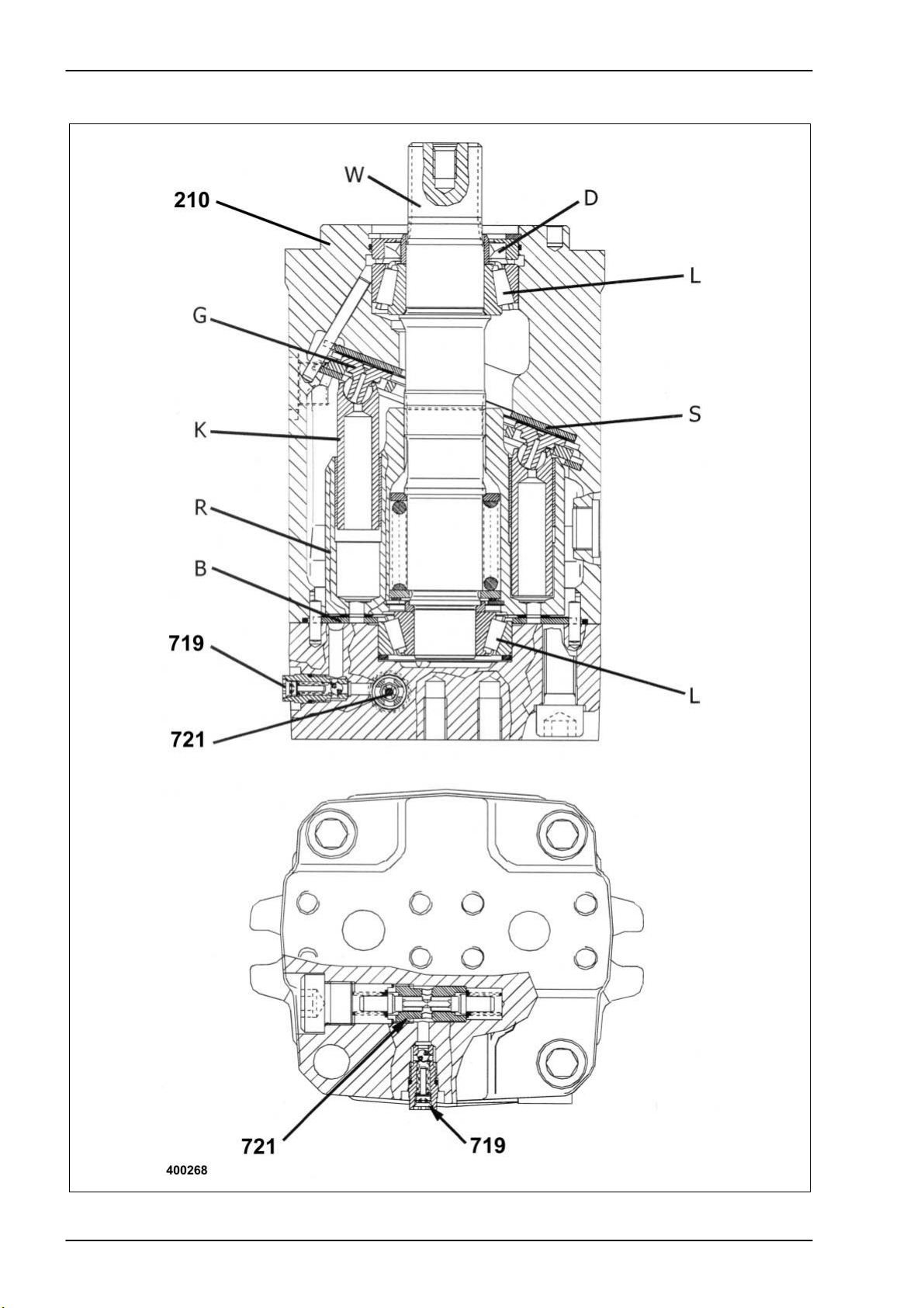
4.5 Ground drive fixed displacement motor
4-14 DO-h-Kap4 04/04
Page 79

TIC Dominator 140 - 150 Hydraulic System
Key to diagram:
Description of function:
See also ground drive
hydraulics circuit diagram
As soon as the diesel engine is started, the feed pump in the pump unit is
210 Ground drive fixed displacement motor ...................... HMF 75
721 Ground drive flush-out shuttle valve
719 Ground drive flush pressure control valve .................. 10 bar
B Control bottom
D Shaft seal
G Slide
K Ram
L Bearing
R Cylinder rotor
S Fixed inclined disc
W Driven shaft
also driven. In this process, the pistons (K) in the cylinder rotor (R) of the
motor unit are pressed against the fixed inclined disc (S) by means of the
slides (G) due to the feed pressure applied on both sides of the highpressure circuit.
As soon as the variable displacement pump is swung out, the pressure
builds up against the nine pistons (K) in the cylinder rotor (R) which is
geared to the driven shaft (W), one after the other. Here the pistons (K)
support themselves against the inclined plane of the fixed inclined disc (S)
and thus convert this energy into a rotating motion against the resistance
at the driven shaft (W).
The direction of rotation here depends on the direction of the oil flow and
thus on the swing direction of the variable displacement pump, with high
pressure and low pressure changing the sides. The motor speed results
from the oil flow quantity therefore from the swing angle of the variable
displacement pump.
The low-pressure side is separated from the high-pressure side inside the
motor unit above the control bottom (B). For sealing purposes, the
cylinder rotor (R) is pushed against the control bottom (B) only by a
compression spring.
The respective high-pressure side in the high-pressure circuit actuates the
ground drive purging shuttle valve (721) in the fixed displacement motor
so the corresponding low-pressure side has a connection to the motor
housing via the ground drive purge pressure control valve (719).
Since the pressure setting of the ground drive purge pressure control
valve (719) is lower than that of the feed pressure relief valve, a constant
oil quantity is exchanged by the feed pump (209) via the restrictor in the
ground drive purge pressure control valve (719).
04/04 DO-h-Kap4 4-15
Page 80

Hydraulic System Dominator 140 - 150 TIC
4-16 DO-h-Kap4 04/04
Page 81

TIC Dominator 140 - 150 Hydraulic System
4.6 Maintenance
Filling instructions Engage 3
rd
gear at the gearshift lever
Disengage all-wheel drive
Apply parking brake
Connect pressure gauges on both high-pressure sides (M1+M2)
Fill tank with hydraulic oil
Pull out engine cut-off system relay and/or cable jumper
Crank the diesel engine for a short period using the electric starting motor
Check and correct the oil level
Repeat procedure until the pressure has risen by approx. 10 bar
Re-install engine cut-off system relay and/or cable jumper
Start diesel engine at min. no-load speed
Load the system with 50-150 bar forward for approx. 1 minute
Load the system with 50-150 bar backward for approx. 1 minute
Shut off diesel engine
Check and correct the oil level if necessary
Set gearshift lever to neutral position
Start diesel engine at min. no-load speed
Swing variable displacement pump forward for approx. 2 minutes
Swing variable displacement pump backward for approx. 2 minutes
Shut off diesel engine
Check and correct the oil level if necessary
Inspection regulations Connect pressure gauges on both high-pressure sides
Apply parking brake
Heat up the system to an operating temperature of approx. 60°C
Move ground speed control lever to neutral position
Set diesel engine to max. no-load speed
Measure the feed pressure: 19 bar
Feed pressure difference on both sides: max. 3 bar
Swing out the variable displacement pump fully to one direction
Pressure drop on low-pressure side: max. 4 bar
Set diesel engine to min. no-load speed
Engage 3
rd
gear in manual transmission
Apply service brake
Slowly swing the variable displacement pump forward for 5 sec. max.
High pressure measurement: 420 to 450 bar
Low pressure measurement: min. 14 bar
Slowly swing the variable displacement pump backward for 5 sec. max.
High pressure measurement: 420 to 450 bar
Low pressure measurement: min. 14 bar
Shut off diesel engine
Remove pressure gauge
04/04 DO-h-Kap4 4-17
Page 82

Hydraulic System Dominator 140 - 150 TIC
4.7 3D cleaning system
4-18 DO-h-Kap4 04/04
Page 83

TIC Dominator 140 - 150 Hydraulic System
Key to diagram:
Description of function:
1 Control head
2 Pendulum
3 Cup
4 Spool
Volumetric flow is applied to port (P) of the control head. When the
pendulum (2) is in the centre position, P is blocked at the spool (4). When
the pendulum changes its position to the right or left, relative to the cup,
the spool (4) is moved. In this process, connections are made between P
and A as well as B and R or between P and B as well as A and R,
depending on the direction in which the pendulum moves.
04/04 DO-h-Kap4 4-19
Page 84

Hydraulic System Dominator 140 - 150 TIC
4-20 DO-h-Kap4 04/04
Page 85

TIC Dominator 140 - 150 Hydraulic System
Position of components
04/04 DO-h-Raster R-1
Page 86

Hydraulic System Dominator 140 - 150 TIC
R-2 DO-h-Raster 04/04
Page 87

TIC Dominator 140 - 150 Hydraulic System
5-k-20
5-k-20
4-i-16
4-i-16
5-i-18
3-o-19
04/04 DO-h-Raster R-3
Page 88

Hydraulic System Dominator 140 - 150 TIC
7-j-19
3-o-16
3-o-19
3-o-19
3-o-19
3-o-19
R-4 DO-h-Raster 04/04
Page 89

TIC Dominator 140 - 150 Hydraulic System
7-j-19
6-g-16
3-o-19
6-n-20
4-k-16
4-m-20
04/04 DO-h-Raster R-5
Page 90

Hydraulic System Dominator 140 - 150 TIC
7-r-18
6-g-16
7-i-18
4-k-16
6-n-20
5-i-18
R-6 DO-h-Raster 04/04
Page 91

TIC Dominator 140 - 150 Hydraulic System
5-i-18
04/04 DO-h-Raster R-7
Page 92

Component grid
Page 93
TIC Dominator 140 - 150 Hydraulic System
Component grid
04/04 DO-h-Raster R-9
Page 94

Hydraulic System Dominator 140 - 150 TIC
R-10 DO-h-Raster 04/04
Page 95

Index
Hydraulic System
Page 96

Hydraulic System Dominator 140 - 150 TIC
Index:
3D cleaning system 4-18
Checking the steering 2-13
C
Ground drive hydraulics 4-1
G
Horizontal reel adjustment 3-20
H
Lock-up valve unit 3-30, 3-24
L
Multi-function valve 4-12
M
Oil pressure 1-6
O
Overall hydraulic system 1-3
Overall hydraulic system circuit diagram with 3D 1-4
Overall hydraulic system circuit diagram without 3D 1-8
Position of components R-1
P
Pressure relief valve 3-6
Raise / lower cutterbar 3-10
R
Raise / lower front attachment 3-10
Rotary coupling 3-14
Steering 2-12
S
Steering actuation 2-12
Steering hydraulics 2-1
Steering hydraulics circuit diagram 2-4
Steering valve unit 2-7
Swing grain tank unloading tube 3-26
Vertical reel adjustment 3-16
V
W
Working hydraulics 3-1
Working hydraulics circuit diagram 3-4
Index-2 DO-h-index 04/04
Page 97

Following the policy of the CLAAS KGaA mbH to improve their products as
technical developments continue, CLAAS reserve the right to make
alterations which must not necessarily correspond to text and illustrations
contained in this publication, and without incurring obligation to alter any
machines previously delivered.
Technical data, dimensions and weights are given as an indication only.
Responsibility for errors or omissions not accepted.
Reproduction or translation of this publication, in whole or part, is not
permitted without the written consent of the CLAAS KGaA mbH.
All rights under the provision of the Copyright Act reserved.
CLAAS KGaA mbH
33426 Harsewinkel
Germany
Our contribution to the environment: CLAAS
have printed this manual on 100 % chlorine
free paper.
Page 98
CLAAS KGaA mbH
Postfach 1163
33426 Harsewinkel
Tel. +49 (0)5247 12-0
www.claas.com
0293 151.1
SYS-H DOMINATOR 140- 150
EN - 01.05 - NF
Printed in Germany
 Loading...