

Page 1

DOMINATOR 150 / 140 / 130
Operator’s Manual
Page 2

a
67075
l
a
u
n
r
O
g
i
n
i
a
l
o
p
ra
e
t
o
r
'
s
m
Page 3

2
EC declaration of conformity
corresponds to EC directive 98/37/EC
We CLAAS Selbstfahrende Erntemaschinen Gesellschaft mit beschränkter Haftung
(Name of supplier)
Postfach 11 63
D-33426 Harsewinkel
(full address of the manufacturer - an authorised representative established in the Community must also give the business name and the
address of the manufacturer)
declare under our sole responsibility that the product
Combine harvester - type:
200 / 156
(Make, Type)
67076
to which this declaration relates corresponds to the relevant basic safety and health requirements of the Directive 98/37/EC Appendix I,
(if applicable)
and to the requirements of the other relevant Directives
89/336/EEC in the version 92/31/EEC.
(Title and/or number and date of issue of the other Directives)
For the relevant implementation of the safety and health requirements mentioned in the Directives, the following
standard(s) and/or technical specification(s) has (have) been respected:
EN 632 - August 1995
(Title and/or number and date of issue of standard(s) and/or technical specification(s))
Technical Management
(J.H. Mohr)
(Name, function and signature of the authorized person)
Quality Management
(U. Krieg)
Harsewinkel,
(Place and date of issue)
00 0293 210 2 - BA DOMINATOR 150/140/130 - 12/09 3
Page 4

2.2
EC Declaration of Conformity
This declaration of conformity is the original declaration of conformity according to
Directive 2006/42/EC
We CLAAS Selbstfahrende Erntemaschinen GmbH
Postfach 11 63, D-33416 Harsewinkel
declare under our sole responsibility, that the product Combine harvester
(type - serial number - trade name)
200 - from 200 01217 - DOMINATOR 150 / 140
156 - from 156 10568 - DOMINATOR 130
to which this declaration relates corresponds to the relevant basic safety and health requirements of Directive
2006/42/EC Appendix I and to the requirements of the other relevant Directives 2004/108/EC.
For the relevant implementation of the safety and health requirements mentioned in the Directives, the following
standard(s) and/or technical specification(s) has (have) been respected: EN 632 - August 1995
67076
The person responsible for documentation in the European Community is: J.H. Mohr, CLAAS Selbstfahrende
Erntemaschinen GmbH, Postfach 11 63, D-33416 Harsewinkel
Technical Management
(J.H. Mohr)
Quality Management
(U. Krieg)
Harsewinkel, 01.10.09
4 00 0293 210 2 - BA DOMINATOR 150/140/130 - 12/09
Page 5

Contents
1 Introduction
1.1 General Information . . . . . . . . . . . . . . . . . . . . . . . . . . . . . . . . . . . . . . . . . . . . . . . . . . . . . . . . . . . . . . 16
1.1.1 How to use this manual . . . . . . . . . . . . . . . . . . . . . . . . . . . . . . . . . . . . . . . . . . . . . . . . . . . . . . 16
1.1.2 Validity of instructions . . . . . . . . . . . . . . . . . . . . . . . . . . . . . . . . . . . . . . . . . . . . . . . . . . . . . . . . 18
1.1.3 Specifications . . . . . . . . . . . . . . . . . . . . . . . . . . . . . . . . . . . . . . . . . . . . . . . . . . . . . . . . . . . . . . 18
1.1.4 Road traffic regulations . . . . . . . . . . . . . . . . . . . . . . . . . . . . . . . . . . . . . . . . . . . . . . . . . . . . . . . 18
1.1.5 Note on electronic engine management . . . . . . . . . . . . . . . . . . . . . . . . . . . . . . . . . . . . . . . . . . 21
1.2 Various components / Machine body . . . . . . . . . . . . . . . . . . . . . . . . . . . . . . . . . . . . . . . . . . . . . . . . 23
1.2.1 Spare parts and technical questions . . . . . . . . . . . . . . . . . . . . . . . . . . . . . . . . . . . . . . . . . . . . . 23
1.2.2 Machine identification plate . . . . . . . . . . . . . . . . . . . . . . . . . . . . . . . . . . . . . . . . . . . . . . . . . . . 23
1.2.3 Identification plate of CATERPILLAR 3056 E engine . . . . . . . . . . . . . . . . . . . . . . . . . . . . . . . . 25
1.2.4 Identification plate of PERKINS 1006-6T engine . . . . . . . . . . . . . . . . . . . . . . . . . . . . . . . . . . . 25
1.2.5 Identification plate of CATERPILLAR C6.6 engine . . . . . . . . . . . . . . . . . . . . . . . . . . . . . . . . . . 26
1.2.6 Drive axle identification plate . . . . . . . . . . . . . . . . . . . . . . . . . . . . . . . . . . . . . . . . . . . . . . . . . . 26
1.2.7 Rear axle identification plate . . . . . . . . . . . . . . . . . . . . . . . . . . . . . . . . . . . . . . . . . . . . . . . . . . 26
1.2.8 Trailer hitch identification plate . . . . . . . . . . . . . . . . . . . . . . . . . . . . . . . . . . . . . . . . . . . . . . . . . 27
1.2.9 Hitch block identification plate . . . . . . . . . . . . . . . . . . . . . . . . . . . . . . . . . . . . . . . . . . . . . . . . . 28
1.2.10 Cab identification plate . . . . . . . . . . . . . . . . . . . . . . . . . . . . . . . . . . . . . . . . . . . . . . . . . . . . . . . 29
1.2.11 Straw chopper identification plate . . . . . . . . . . . . . . . . . . . . . . . . . . . . . . . . . . . . . . . . . . . . . . . 29
67075
2 Sectional view of machine
2.1 Attachment parts / machine body . . . . . . . . . . . . . . . . . . . . . . . . . . . . . . . . . . . . . . . . . . . . . . . . . . . 30
2.1.1 Machine overview . . . . . . . . . . . . . . . . . . . . . . . . . . . . . . . . . . . . . . . . . . . . . . . . . . . . . . . . . . . 30
2.1.2 Access to the workplace and maintenance areas . . . . . . . . . . . . . . . . . . . . . . . . . . . . . . . . . . 32
3 Safety
3.1 General Information . . . . . . . . . . . . . . . . . . . . . . . . . . . . . . . . . . . . . . . . . . . . . . . . . . . . . . . . . . . . . . 34
3.1.1 General information . . . . . . . . . . . . . . . . . . . . . . . . . . . . . . . . . . . . . . . . . . . . . . . . . . . . . . . . . 34
3.1.2 Important information . . . . . . . . . . . . . . . . . . . . . . . . . . . . . . . . . . . . . . . . . . . . . . . . . . . . . . . . 34
3.1.3 Intended use . . . . . . . . . . . . . . . . . . . . . . . . . . . . . . . . . . . . . . . . . . . . . . . . . . . . . . . . . . . . . . . 34
3.1.4 Reasonable foreseeable misuse . . . . . . . . . . . . . . . . . . . . . . . . . . . . . . . . . . . . . . . . . . . . . . . 35
3.1.5 Safety and accident prevention regulations . . . . . . . . . . . . . . . . . . . . . . . . . . . . . . . . . . . . . . . 36
3.1.6 General safety and accident prevention regulations for combine harvesters . . . . . . . . . . . . . . 37
3.1.7 Prior to operation, general . . . . . . . . . . . . . . . . . . . . . . . . . . . . . . . . . . . . . . . . . . . . . . . . . . . . 37
3.1.8 Additional weights . . . . . . . . . . . . . . . . . . . . . . . . . . . . . . . . . . . . . . . . . . . . . . . . . . . . . . . . . . . 38
3.1.9 Transporting passengers . . . . . . . . . . . . . . . . . . . . . . . . . . . . . . . . . . . . . . . . . . . . . . . . . . . . . 38
3.1.10 General driving operations . . . . . . . . . . . . . . . . . . . . . . . . . . . . . . . . . . . . . . . . . . . . . . . . . . . . 38
3.1.11 Automotive operation of combine harvester . . . . . . . . . . . . . . . . . . . . . . . . . . . . . . . . . . . . . . . 38
3.1.12 Driving operations on slopes . . . . . . . . . . . . . . . . . . . . . . . . . . . . . . . . . . . . . . . . . . . . . . . . . . 39
3.1.13 Leaving the machine . . . . . . . . . . . . . . . . . . . . . . . . . . . . . . . . . . . . . . . . . . . . . . . . . . . . . . . . 39
3.1.14 Front attachments and trailers . . . . . . . . . . . . . . . . . . . . . . . . . . . . . . . . . . . . . . . . . . . . . . . . . 39
3.1.15 Crop receptacle / straw receptacle . . . . . . . . . . . . . . . . . . . . . . . . . . . . . . . . . . . . . . . . . . . . . . 40
3.1.16 Grain delivery . . . . . . . . . . . . . . . . . . . . . . . . . . . . . . . . . . . . . . . . . . . . . . . . . . . . . . . . . . . . . . 40
3.1.17 Air conditioner . . . . . . . . . . . . . . . . . . . . . . . . . . . . . . . . . . . . . . . . . . . . . . . . . . . . . . . . . . . . . 40
3.1.18 Adjustment and maintenance work . . . . . . . . . . . . . . . . . . . . . . . . . . . . . . . . . . . . . . . . . . . . . 40
3.1.19 Accumulators . . . . . . . . . . . . . . . . . . . . . . . . . . . . . . . . . . . . . . . . . . . . . . . . . . . . . . . . . . . . . . 41
00 0293 210 2 - BA DOMINATOR 150/140/130 - 12/09 5
Page 6

3.1.20 Antifreeze . . . . . . . . . . . . . . . . . . . . . . . . . . . . . . . . . . . . . . . . . . . . . . . . . . . . . . . . . . . . . . . . . 41
3.1.21 First aid measures . . . . . . . . . . . . . . . . . . . . . . . . . . . . . . . . . . . . . . . . . . . . . . . . . . . . . . . . . . 42
3.1.22 Decommissioning and disposal . . . . . . . . . . . . . . . . . . . . . . . . . . . . . . . . . . . . . . . . . . . . . . . . 42
3.1.23 Applying the feeder housing safety lock . . . . . . . . . . . . . . . . . . . . . . . . . . . . . . . . . . . . . . . . . 43
3.1.24 Moving out the feed rake conveyor safety lock . . . . . . . . . . . . . . . . . . . . . . . . . . . . . . . . . . . . 43
3.1.25 Secure the machine with wheel chocks so it will not roll away . . . . . . . . . . . . . . . . . . . . . . . . 44
3.1.26 Securing the straw guide apron in raised position . . . . . . . . . . . . . . . . . . . . . . . . . . . . . . . . . . 45
3.1.27 Jack up the machine . . . . . . . . . . . . . . . . . . . . . . . . . . . . . . . . . . . . . . . . . . . . . . . . . . . . . . . . 45
3.1.28 Fire extinguisher . . . . . . . . . . . . . . . . . . . . . . . . . . . . . . . . . . . . . . . . . . . . . . . . . . . . . . . . . . . 45
3.1.29 Battery isolating switch . . . . . . . . . . . . . . . . . . . . . . . . . . . . . . . . . . . . . . . . . . . . . . . . . . . . . . 46
3.1.30 Danger of injury due to escaping hydraulic liquid . . . . . . . . . . . . . . . . . . . . . . . . . . . . . . . . . . 46
3.1.31 Loading and tying down the machine . . . . . . . . . . . . . . . . . . . . . . . . . . . . . . . . . . . . . . . . . . . 47
3.1.32 Removing the lift eyes . . . . . . . . . . . . . . . . . . . . . . . . . . . . . . . . . . . . . . . . . . . . . . . . . . . . . . . 49
3.2 Safety rules . . . . . . . . . . . . . . . . . . . . . . . . . . . . . . . . . . . . . . . . . . . . . . . . . . . . . . . . . . . . . . . . . . . . . 50
3.2.1 Identification of warning and danger signs . . . . . . . . . . . . . . . . . . . . . . . . . . . . . . . . . . . . . . . 50
3.3 Safety decals . . . . . . . . . . . . . . . . . . . . . . . . . . . . . . . . . . . . . . . . . . . . . . . . . . . . . . . . . . . . . . . . . . . 51
3.3.1 General information on safety decals . . . . . . . . . . . . . . . . . . . . . . . . . . . . . . . . . . . . . . . . . . . 51
3.3.2 Engine . . . . . . . . . . . . . . . . . . . . . . . . . . . . . . . . . . . . . . . . . . . . . . . . . . . . . . . . . . . . . . . . . . . 52
3.3.3 Chassis . . . . . . . . . . . . . . . . . . . . . . . . . . . . . . . . . . . . . . . . . . . . . . . . . . . . . . . . . . . . . . . . . . 54
3.3.4 Cab / Operator's platform . . . . . . . . . . . . . . . . . . . . . . . . . . . . . . . . . . . . . . . . . . . . . . . . . . . . . 55
3.3.5 Feeder unit . . . . . . . . . . . . . . . . . . . . . . . . . . . . . . . . . . . . . . . . . . . . . . . . . . . . . . . . . . . . . . . . 57
3.3.6 Threshing mechanism . . . . . . . . . . . . . . . . . . . . . . . . . . . . . . . . . . . . . . . . . . . . . . . . . . . . . . . 60
3.3.7 Separation . . . . . . . . . . . . . . . . . . . . . . . . . . . . . . . . . . . . . . . . . . . . . . . . . . . . . . . . . . . . . . . . 62
3.3.8 Crop receptacle / straw receptacle . . . . . . . . . . . . . . . . . . . . . . . . . . . . . . . . . . . . . . . . . . . . . 64
3.3.9 Grain delivery . . . . . . . . . . . . . . . . . . . . . . . . . . . . . . . . . . . . . . . . . . . . . . . . . . . . . . . . . . . . . . 67
3.3.10 Various components / Machine body . . . . . . . . . . . . . . . . . . . . . . . . . . . . . . . . . . . . . . . . . . . . 72
3.4 Safety decals . . . . . . . . . . . . . . . . . . . . . . . . . . . . . . . . . . . . . . . . . . . . . . . . . . . . . . . . . . . . . . . . . . . 74
3.4.1 General instructions on safety decals . . . . . . . . . . . . . . . . . . . . . . . . . . . . . . . . . . . . . . . . . . . 74
3.4.2 Chassis . . . . . . . . . . . . . . . . . . . . . . . . . . . . . . . . . . . . . . . . . . . . . . . . . . . . . . . . . . . . . . . . . . 74
67075
4 Specifications
4.1 DOMINATOR 150 / 140 / 130 . . . . . . . . . . . . . . . . . . . . . . . . . . . . . . . . . . . . . . . . . . . . . . . . . . . . . . . 75
4.1.1 General information . . . . . . . . . . . . . . . . . . . . . . . . . . . . . . . . . . . . . . . . . . . . . . . . . . . . . . . . . 75
4.1.2 CATERPILLAR C6.6 engine . . . . . . . . . . . . . . . . . . . . . . . . . . . . . . . . . . . . . . . . . . . . . . . . . . 75
4.1.3 CATERPILLAR 3056E engine . . . . . . . . . . . . . . . . . . . . . . . . . . . . . . . . . . . . . . . . . . . . . . . . . 76
4.1.4 Perkins 1006-T6 engine . . . . . . . . . . . . . . . . . . . . . . . . . . . . . . . . . . . . . . . . . . . . . . . . . . . . . . 76
4.1.5 Chassis . . . . . . . . . . . . . . . . . . . . . . . . . . . . . . . . . . . . . . . . . . . . . . . . . . . . . . . . . . . . . . . . . . 77
4.1.6 Tyre pressures . . . . . . . . . . . . . . . . . . . . . . . . . . . . . . . . . . . . . . . . . . . . . . . . . . . . . . . . . . . . . 78
4.1.7 Chassis track width . . . . . . . . . . . . . . . . . . . . . . . . . . . . . . . . . . . . . . . . . . . . . . . . . . . . . . . . . 80
4.1.8 Brake . . . . . . . . . . . . . . . . . . . . . . . . . . . . . . . . . . . . . . . . . . . . . . . . . . . . . . . . . . . . . . . . . . . . 81
4.1.9 Steering . . . . . . . . . . . . . . . . . . . . . . . . . . . . . . . . . . . . . . . . . . . . . . . . . . . . . . . . . . . . . . . . . . 81
4.1.10 Electric system / Electronics . . . . . . . . . . . . . . . . . . . . . . . . . . . . . . . . . . . . . . . . . . . . . . . . . . 82
4.1.11 Cab / Operator's platform . . . . . . . . . . . . . . . . . . . . . . . . . . . . . . . . . . . . . . . . . . . . . . . . . . . . . 82
4.1.12 Intake . . . . . . . . . . . . . . . . . . . . . . . . . . . . . . . . . . . . . . . . . . . . . . . . . . . . . . . . . . . . . . . . . . . . 82
4.1.13 Threshing mechanism . . . . . . . . . . . . . . . . . . . . . . . . . . . . . . . . . . . . . . . . . . . . . . . . . . . . . . . 83
4.1.14 Separation . . . . . . . . . . . . . . . . . . . . . . . . . . . . . . . . . . . . . . . . . . . . . . . . . . . . . . . . . . . . . . . . 83
4.1.15 Cleaning unit . . . . . . . . . . . . . . . . . . . . . . . . . . . . . . . . . . . . . . . . . . . . . . . . . . . . . . . . . . . . . . 84
4.1.16 Grain delivery . . . . . . . . . . . . . . . . . . . . . . . . . . . . . . . . . . . . . . . . . . . . . . . . . . . . . . . . . . . . . . 84
6 00 0293 210 2 - BA DOMINATOR 150/140/130 - 12/09
Page 7

4.1.17 Attachment parts / machine body dimensions . . . . . . . . . . . . . . . . . . . . . . . . . . . . . . . . . . . . . 84
4.1.18 Attachment parts / machine body weights . . . . . . . . . . . . . . . . . . . . . . . . . . . . . . . . . . . . . . . . 86
5 Prior to initial operation
5.1 General Information . . . . . . . . . . . . . . . . . . . . . . . . . . . . . . . . . . . . . . . . . . . . . . . . . . . . . . . . . . . . . . 87
5.1.1 General warnings Prior to initial operation . . . . . . . . . . . . . . . . . . . . . . . . . . . . . . . . . . . . . . . . 87
5.1.2 Initial operation check list . . . . . . . . . . . . . . . . . . . . . . . . . . . . . . . . . . . . . . . . . . . . . . . . . . . . . 87
5.2 Chassis . . . . . . . . . . . . . . . . . . . . . . . . . . . . . . . . . . . . . . . . . . . . . . . . . . . . . . . . . . . . . . . . . . . . . . . . 89
5.2.1 Removing / installing the wheels . . . . . . . . . . . . . . . . . . . . . . . . . . . . . . . . . . . . . . . . . . . . . . . 89
5.2.2 Overview of rear axle . . . . . . . . . . . . . . . . . . . . . . . . . . . . . . . . . . . . . . . . . . . . . . . . . . . . . . . . 89
5.2.3 Converting the rear axle from transport to working position . . . . . . . . . . . . . . . . . . . . . . . . . . . 90
5.2.4 Rear axle 00 0649 950 1 – Adjusting the track width . . . . . . . . . . . . . . . . . . . . . . . . . . . . . . . . 91
5.3 Hitch . . . . . . . . . . . . . . . . . . . . . . . . . . . . . . . . . . . . . . . . . . . . . . . . . . . . . . . . . . . . . . . . . . . . . . . . . . . 93
5.3.1 Installing the trailer hitch (accessories) . . . . . . . . . . . . . . . . . . . . . . . . . . . . . . . . . . . . . . . . . . 93
5.4 Electrical / electronic equipment . . . . . . . . . . . . . . . . . . . . . . . . . . . . . . . . . . . . . . . . . . . . . . . . . . . . 94
5.4.1 Installing the fan / air conditioner fuse . . . . . . . . . . . . . . . . . . . . . . . . . . . . . . . . . . . . . . . . . . . 94
5.5 Feeder unit . . . . . . . . . . . . . . . . . . . . . . . . . . . . . . . . . . . . . . . . . . . . . . . . . . . . . . . . . . . . . . . . . . . . . 95
5.5.1 Fitting / adjusting the mounting plates . . . . . . . . . . . . . . . . . . . . . . . . . . . . . . . . . . . . . . . . . . . 95
5.5.2 Aligning the coupling pin . . . . . . . . . . . . . . . . . . . . . . . . . . . . . . . . . . . . . . . . . . . . . . . . . . . . . 95
5.5.3 Checking the front attachment cylinders . . . . . . . . . . . . . . . . . . . . . . . . . . . . . . . . . . . . . . . . . 96
5.5.4 Checking the cutterbar float springs . . . . . . . . . . . . . . . . . . . . . . . . . . . . . . . . . . . . . . . . . . . . . 97
5.6 Grain delivery . . . . . . . . . . . . . . . . . . . . . . . . . . . . . . . . . . . . . . . . . . . . . . . . . . . . . . . . . . . . . . . . . . . 99
5.6.1 Closing the service aperture on the grain tank unloading tube . . . . . . . . . . . . . . . . . . . . . . . . 99
5.6.2 Installing the grain tank safety device . . . . . . . . . . . . . . . . . . . . . . . . . . . . . . . . . . . . . . . . . . . . 99
67075
6 Prior to each operation
6.1 General Information . . . . . . . . . . . . . . . . . . . . . . . . . . . . . . . . . . . . . . . . . . . . . . . . . . . . . . . . . . . . . 101
6.1.1 General warnings Prior to operation . . . . . . . . . . . . . . . . . . . . . . . . . . . . . . . . . . . . . . . . . . . . 101
6.1.2 Check list for daily operation . . . . . . . . . . . . . . . . . . . . . . . . . . . . . . . . . . . . . . . . . . . . . . . . . 101
7 Overview of controls
7.1 General Information . . . . . . . . . . . . . . . . . . . . . . . . . . . . . . . . . . . . . . . . . . . . . . . . . . . . . . . . . . . . . 103
7.1.1 General warnings - Overview of controls . . . . . . . . . . . . . . . . . . . . . . . . . . . . . . . . . . . . . . . . 103
7.2 Cab / Operator's platform . . . . . . . . . . . . . . . . . . . . . . . . . . . . . . . . . . . . . . . . . . . . . . . . . . . . . . . . . 104
7.2.1 Overview of operator's platform (DOMINATOR 130) . . . . . . . . . . . . . . . . . . . . . . . . . . . . . . . 104
7.2.2 Overview of operator's platform (DOMINATOR 150/140) . . . . . . . . . . . . . . . . . . . . . . . . . . . . 106
7.2.3 Hydraulic system control unit (DOMINATOR 130 lift hydraulic system) . . . . . . . . . . . . . . . . . 107
7.2.4 Multifunction handle (DOMINATOR 150 / 140) . . . . . . . . . . . . . . . . . . . . . . . . . . . . . . . . . . . 108
7.2.5 Switch console (DOMINATOR 130) . . . . . . . . . . . . . . . . . . . . . . . . . . . . . . . . . . . . . . . . . . . . 108
7.2.6 Diesel engine speed adjustment rotary switch (DOMINATOR 130,
CATERPILLAR C-6.6, 3056 E) . . . . . . . . . . . . . . . . . . . . . . . . . . . . . . . . . . . . . . . . . . . . . . . . 109
7.2.7 Diesel engine speed lever (DOMINATOR 130, Perkins 1006-T6) . . . . . . . . . . . . . . . . . . . . . 109
7.2.8 Function of warning lights 7 and 8 (DOMINATOR 130) . . . . . . . . . . . . . . . . . . . . . . . . . . . . . 110
7.2.9 Switch console (DOMINATOR 150 / 140) . . . . . . . . . . . . . . . . . . . . . . . . . . . . . . . . . . . . . . . 111
7.2.10 Diesel engine speed rotary switch (DOMINATOR 150 / 140) . . . . . . . . . . . . . . . . . . . . . . . . . 112
7.2.11 Function of warning lights 15 and 18 (DOMINATOR 150 / 140) . . . . . . . . . . . . . . . . . . . . . . . 113
7.2.12 Overview of steering column . . . . . . . . . . . . . . . . . . . . . . . . . . . . . . . . . . . . . . . . . . . . . . . . . 114
7.2.13 Cab roof controls . . . . . . . . . . . . . . . . . . . . . . . . . . . . . . . . . . . . . . . . . . . . . . . . . . . . . . . . . . 117
7.2.14 Cab with fan . . . . . . . . . . . . . . . . . . . . . . . . . . . . . . . . . . . . . . . . . . . . . . . . . . . . . . . . . . . . . . 118
00 0293 210 2 - BA DOMINATOR 150/140/130 - 12/09 7
Page 8

7.2.15 Cab with air conditioner (with York compressor) . . . . . . . . . . . . . . . . . . . . . . . . . . . . . . . . . . .118
7.2.16 Cab with air conditioner (with Sanden compressor) . . . . . . . . . . . . . . . . . . . . . . . . . . . . . . . 120
7.2.17 Cab with fan and heater . . . . . . . . . . . . . . . . . . . . . . . . . . . . . . . . . . . . . . . . . . . . . . . . . . . . . 121
7.2.18 Control levers . . . . . . . . . . . . . . . . . . . . . . . . . . . . . . . . . . . . . . . . . . . . . . . . . . . . . . . . . . . . . 122
7.2.19 Functions monitor . . . . . . . . . . . . . . . . . . . . . . . . . . . . . . . . . . . . . . . . . . . . . . . . . . . . . . . . . 122
7.3 Attachment parts / machine body . . . . . . . . . . . . . . . . . . . . . . . . . . . . . . . . . . . . . . . . . . . . . . . . . . 124
7.3.1 Worklights . . . . . . . . . . . . . . . . . . . . . . . . . . . . . . . . . . . . . . . . . . . . . . . . . . . . . . . . . . . . . . . 124
7.3.2 Cab . . . . . . . . . . . . . . . . . . . . . . . . . . . . . . . . . . . . . . . . . . . . . . . . . . . . . . . . . . . . . . . . . . . . 124
7.3.3 Sun roof . . . . . . . . . . . . . . . . . . . . . . . . . . . . . . . . . . . . . . . . . . . . . . . . . . . . . . . . . . . . . . . . . 125
7.3.4 Tool box . . . . . . . . . . . . . . . . . . . . . . . . . . . . . . . . . . . . . . . . . . . . . . . . . . . . . . . . . . . . . . . . . 125
8 Mounting/removing front attachment
8.1 General Information . . . . . . . . . . . . . . . . . . . . . . . . . . . . . . . . . . . . . . . . . . . . . . . . . . . . . . . . . . . . . 126
8.1.1 General warnings Installing / removing the front attachment . . . . . . . . . . . . . . . . . . . . . . . . . 126
8.2 Installing the front attachment . . . . . . . . . . . . . . . . . . . . . . . . . . . . . . . . . . . . . . . . . . . . . . . . . . . . 127
8.2.1 Suspending front attachment . . . . . . . . . . . . . . . . . . . . . . . . . . . . . . . . . . . . . . . . . . . . . . . . . 127
8.2.2 Interlocking the front attachment . . . . . . . . . . . . . . . . . . . . . . . . . . . . . . . . . . . . . . . . . . . . . . 127
8.2.3 Installing universal drive shaft . . . . . . . . . . . . . . . . . . . . . . . . . . . . . . . . . . . . . . . . . . . . . . . . 128
8.2.4 Connecting the hydraulic system . . . . . . . . . . . . . . . . . . . . . . . . . . . . . . . . . . . . . . . . . . . . . . 130
8.2.5 Connecting the electric equipment (accessory) . . . . . . . . . . . . . . . . . . . . . . . . . . . . . . . . . . . 130
8.2.6 Removing the stands . . . . . . . . . . . . . . . . . . . . . . . . . . . . . . . . . . . . . . . . . . . . . . . . . . . . . . . 131
8.3 Removing the front attachment . . . . . . . . . . . . . . . . . . . . . . . . . . . . . . . . . . . . . . . . . . . . . . . . . . . 133
8.3.1 Fitting the stands . . . . . . . . . . . . . . . . . . . . . . . . . . . . . . . . . . . . . . . . . . . . . . . . . . . . . . . . . . 133
8.3.2 Disconnecting the hydraulic system . . . . . . . . . . . . . . . . . . . . . . . . . . . . . . . . . . . . . . . . . . . 134
8.3.3 Disconnecting the electric equipment (accessory) . . . . . . . . . . . . . . . . . . . . . . . . . . . . . . . . 134
8.3.4 Removing universal drive shaft . . . . . . . . . . . . . . . . . . . . . . . . . . . . . . . . . . . . . . . . . . . . . . . 135
8.3.5 Unlocking the front attachment . . . . . . . . . . . . . . . . . . . . . . . . . . . . . . . . . . . . . . . . . . . . . . . 136
8.3.6 Unhitching front attachment . . . . . . . . . . . . . . . . . . . . . . . . . . . . . . . . . . . . . . . . . . . . . . . . . . 136
67075
9 Driving and transportation
9.1 General Information . . . . . . . . . . . . . . . . . . . . . . . . . . . . . . . . . . . . . . . . . . . . . . . . . . . . . . . . . . . . . 138
9.1.1 General warnings - Driving and transportation . . . . . . . . . . . . . . . . . . . . . . . . . . . . . . . . . . . 138
9.1.2 Preparing road travel . . . . . . . . . . . . . . . . . . . . . . . . . . . . . . . . . . . . . . . . . . . . . . . . . . . . . . . 138
9.1.3 Preparing fieldwork . . . . . . . . . . . . . . . . . . . . . . . . . . . . . . . . . . . . . . . . . . . . . . . . . . . . . . . . 141
9.2 Engine . . . . . . . . . . . . . . . . . . . . . . . . . . . . . . . . . . . . . . . . . . . . . . . . . . . . . . . . . . . . . . . . . . . . . . . . 143
9.2.1 Adjusting the diesel engine speed (DOMINATOR 150 / 140) . . . . . . . . . . . . . . . . . . . . . . . . 143
9.2.2 Starting the diesel engine (DOMINATOR 150 / 140) . . . . . . . . . . . . . . . . . . . . . . . . . . . . . . . 143
9.2.3 Stopping the diesel engine (DOMINATOR 150 / 140) . . . . . . . . . . . . . . . . . . . . . . . . . . . . . . 145
9.2.4 Adjusting the diesel engine speed (DOMINATOR 130) . . . . . . . . . . . . . . . . . . . . . . . . . . . . . 146
9.2.5 Starting the diesel engine (DOMINATOR 130) . . . . . . . . . . . . . . . . . . . . . . . . . . . . . . . . . . . 146
9.2.6 Stopping the diesel engine (DOMINATOR 130) . . . . . . . . . . . . . . . . . . . . . . . . . . . . . . . . . . 148
9.3 Chassis . . . . . . . . . . . . . . . . . . . . . . . . . . . . . . . . . . . . . . . . . . . . . . . . . . . . . . . . . . . . . . . . . . . . . . . 150
9.3.1 Ground speed control lever (DOMINATOR 150 / 140) . . . . . . . . . . . . . . . . . . . . . . . . . . . . . 150
9.3.2 Shifting a gear (DOMINATOR 150 / 140) . . . . . . . . . . . . . . . . . . . . . . . . . . . . . . . . . . . . . . . . 150
9.3.3 Ground speed control lever (DOMINATOR 130) . . . . . . . . . . . . . . . . . . . . . . . . . . . . . . . . . . 151
9.3.4 Shifting a gear (DOMINATOR 130) . . . . . . . . . . . . . . . . . . . . . . . . . . . . . . . . . . . . . . . . . . . . 152
9.3.5 Adjusting the ground speed control lever actuating resistance
(DOMINATOR 150 / 140) . . . . . . . . . . . . . . . . . . . . . . . . . . . . . . . . . . . . . . . . . . . . . . . . . . . . 153
9.3.6 Driving behaviour . . . . . . . . . . . . . . . . . . . . . . . . . . . . . . . . . . . . . . . . . . . . . . . . . . . . . . . . . . 154
8 00 0293 210 2 - BA DOMINATOR 150/140/130 - 12/09
Page 9

67075
9.3.7 Towing the machine . . . . . . . . . . . . . . . . . . . . . . . . . . . . . . . . . . . . . . . . . . . . . . . . . . . . . . . . 154
9.3.8 Forward towing . . . . . . . . . . . . . . . . . . . . . . . . . . . . . . . . . . . . . . . . . . . . . . . . . . . . . . . . . . . . 155
9.3.9 Reverse towing . . . . . . . . . . . . . . . . . . . . . . . . . . . . . . . . . . . . . . . . . . . . . . . . . . . . . . . . . . . . 155
9.4 Brake . . . . . . . . . . . . . . . . . . . . . . . . . . . . . . . . . . . . . . . . . . . . . . . . . . . . . . . . . . . . . . . . . . . . . . . . . 156
9.4.1 Applying the parking brake . . . . . . . . . . . . . . . . . . . . . . . . . . . . . . . . . . . . . . . . . . . . . . . . . . . 156
9.4.2 Releasing the parking brake . . . . . . . . . . . . . . . . . . . . . . . . . . . . . . . . . . . . . . . . . . . . . . . . . . 156
9.4.3 Foot brake . . . . . . . . . . . . . . . . . . . . . . . . . . . . . . . . . . . . . . . . . . . . . . . . . . . . . . . . . . . . . . . 156
9.4.4 Braking / stopping the machine (DOMINATOR 150 / 140) . . . . . . . . . . . . . . . . . . . . . . . . . . . 157
9.4.5 Braking / stopping the machine (DOMINATOR 130) . . . . . . . . . . . . . . . . . . . . . . . . . . . . . . . 158
9.4.6 Parking the machine . . . . . . . . . . . . . . . . . . . . . . . . . . . . . . . . . . . . . . . . . . . . . . . . . . . . . . . . 159
9.5 Steering . . . . . . . . . . . . . . . . . . . . . . . . . . . . . . . . . . . . . . . . . . . . . . . . . . . . . . . . . . . . . . . . . . . . . . . 160
9.5.1 Steering . . . . . . . . . . . . . . . . . . . . . . . . . . . . . . . . . . . . . . . . . . . . . . . . . . . . . . . . . . . . . . . . . 160
9.5.2 Adjusting the steering column . . . . . . . . . . . . . . . . . . . . . . . . . . . . . . . . . . . . . . . . . . . . . . . . 160
9.6 Hitch . . . . . . . . . . . . . . . . . . . . . . . . . . . . . . . . . . . . . . . . . . . . . . . . . . . . . . . . . . . . . . . . . . . . . . . . . . 161
9.6.1 Hitching the trailer . . . . . . . . . . . . . . . . . . . . . . . . . . . . . . . . . . . . . . . . . . . . . . . . . . . . . . . . . 161
9.6.2 Unhitching the trailer . . . . . . . . . . . . . . . . . . . . . . . . . . . . . . . . . . . . . . . . . . . . . . . . . . . . . . . 164
9.7 Cab / Operator's platform . . . . . . . . . . . . . . . . . . . . . . . . . . . . . . . . . . . . . . . . . . . . . . . . . . . . . . . . . 166
9.7.1 Adjusting the driver's seat with mechanical suspension (standard version) . . . . . . . . . . . . . . 166
9.7.2 Adjusting the driver's seat with mechanical suspension (standard version) . . . . . . . . . . . . . . 167
9.7.3 Adjusting the mechanically suspended driver's seat (option) . . . . . . . . . . . . . . . . . . . . . . . . . 169
9.8 Various components / Machine body . . . . . . . . . . . . . . . . . . . . . . . . . . . . . . . . . . . . . . . . . . . . . . . 171
9.8.1 Rotating the front ladder (standard) . . . . . . . . . . . . . . . . . . . . . . . . . . . . . . . . . . . . . . . . . . . . 171
9.8.2 Adjusting the rear ladder . . . . . . . . . . . . . . . . . . . . . . . . . . . . . . . . . . . . . . . . . . . . . . . . . . . . 171
10 Fieldwork settings
10.1 General Information . . . . . . . . . . . . . . . . . . . . . . . . . . . . . . . . . . . . . . . . . . . . . . . . . . . . . . . . . . . . . 173
10.1.1 General warnings - Fieldwork settings . . . . . . . . . . . . . . . . . . . . . . . . . . . . . . . . . . . . . . . . . . 173
10.2 Feeder unit . . . . . . . . . . . . . . . . . . . . . . . . . . . . . . . . . . . . . . . . . . . . . . . . . . . . . . . . . . . . . . . . . . . . 174
10.2.1 Adjusting the cutting height indicator . . . . . . . . . . . . . . . . . . . . . . . . . . . . . . . . . . . . . . . . . . . 174
10.2.2 Adjusting the scraper profiles . . . . . . . . . . . . . . . . . . . . . . . . . . . . . . . . . . . . . . . . . . . . . . . . . 174
10.2.3 Adjusting the height of the feeder chain . . . . . . . . . . . . . . . . . . . . . . . . . . . . . . . . . . . . . . . . . 175
10.2.4 Adjusting the front attachment drop rate (DOMINATOR 150) . . . . . . . . . . . . . . . . . . . . . . . . 176
10.3 Threshing mechanism . . . . . . . . . . . . . . . . . . . . . . . . . . . . . . . . . . . . . . . . . . . . . . . . . . . . . . . . . . . 177
10.3.1 Removing / installing threshing concave segments (Multicrop concave) . . . . . . . . . . . . . . . . 177
10.3.2 Adjusting the basic concave adjustment . . . . . . . . . . . . . . . . . . . . . . . . . . . . . . . . . . . . . . . . 177
10.4 Separation . . . . . . . . . . . . . . . . . . . . . . . . . . . . . . . . . . . . . . . . . . . . . . . . . . . . . . . . . . . . . . . . . . . . . 180
10.4.1 Adjusting the separation performance monitor sensors . . . . . . . . . . . . . . . . . . . . . . . . . . . . . 180
10.5 Cleaning unit . . . . . . . . . . . . . . . . . . . . . . . . . . . . . . . . . . . . . . . . . . . . . . . . . . . . . . . . . . . . . . . . . . . 181
10.5.1 Checking / adjusting the fan speed display . . . . . . . . . . . . . . . . . . . . . . . . . . . . . . . . . . . . . . 181
10.5.2 Adjusting the cleaning performance monitor sensors . . . . . . . . . . . . . . . . . . . . . . . . . . . . . . . 181
10.5.3 Removing the sieves . . . . . . . . . . . . . . . . . . . . . . . . . . . . . . . . . . . . . . . . . . . . . . . . . . . . . . . 182
10.5.4 Installing the sieves . . . . . . . . . . . . . . . . . . . . . . . . . . . . . . . . . . . . . . . . . . . . . . . . . . . . . . . . 183
10.6 Crop receptacle / straw receptacle . . . . . . . . . . . . . . . . . . . . . . . . . . . . . . . . . . . . . . . . . . . . . . . . . 185
10.6.1 Removing the straw guide plate (straw chopper with standard spreader) . . . . . . . . . . . . . . . 185
10.6.2 Installing the straw guide plate (straw chopper with standard spreader) . . . . . . . . . . . . . . . . 186
10.6.3 Unscrewing the free-swinging knives . . . . . . . . . . . . . . . . . . . . . . . . . . . . . . . . . . . . . . . . . . . 187
10.6.4 Bolting down the free-swinging knives . . . . . . . . . . . . . . . . . . . . . . . . . . . . . . . . . . . . . . . . . . 188
10.6.5 Straw chopper sieves installation position . . . . . . . . . . . . . . . . . . . . . . . . . . . . . . . . . . . . . . . 189
00 0293 210 2 - BA DOMINATOR 150/140/130 - 12/09 9
Page 10

10.7 Grain delivery . . . . . . . . . . . . . . . . . . . . . . . . . . . . . . . . . . . . . . . . . . . . . . . . . . . . . . . . . . . . . . . . . . 191
10.7.1 Adjusting the grain tank full indicator DOMINATOR 150 . . . . . . . . . . . . . . . . . . . . . . . . . . . . 191
11 Fieldwork
11.1 General Information . . . . . . . . . . . . . . . . . . . . . . . . . . . . . . . . . . . . . . . . . . . . . . . . . . . . . . . . . . . . . 193
11.1.1 General warnings Fieldwork . . . . . . . . . . . . . . . . . . . . . . . . . . . . . . . . . . . . . . . . . . . . . . . . . 193
11.2 Description and function . . . . . . . . . . . . . . . . . . . . . . . . . . . . . . . . . . . . . . . . . . . . . . . . . . . . . . . . . 194
11.2.1 Cutterbar . . . . . . . . . . . . . . . . . . . . . . . . . . . . . . . . . . . . . . . . . . . . . . . . . . . . . . . . . . . . . . . . 194
11.2.2 Threshing mechanism . . . . . . . . . . . . . . . . . . . . . . . . . . . . . . . . . . . . . . . . . . . . . . . . . . . . . . 195
11.2.3 Straw walker . . . . . . . . . . . . . . . . . . . . . . . . . . . . . . . . . . . . . . . . . . . . . . . . . . . . . . . . . . . . . 195
11.2.4 Cleaning unit . . . . . . . . . . . . . . . . . . . . . . . . . . . . . . . . . . . . . . . . . . . . . . . . . . . . . . . . . . . . . 195
11.2.5 Disawning . . . . . . . . . . . . . . . . . . . . . . . . . . . . . . . . . . . . . . . . . . . . . . . . . . . . . . . . . . . . . . . 195
11.3 Considerations before combining . . . . . . . . . . . . . . . . . . . . . . . . . . . . . . . . . . . . . . . . . . . . . . . . . 196
11.3.1 When combining, remember: . . . . . . . . . . . . . . . . . . . . . . . . . . . . . . . . . . . . . . . . . . . . . . . . . 196
11.4 Front attachment . . . . . . . . . . . . . . . . . . . . . . . . . . . . . . . . . . . . . . . . . . . . . . . . . . . . . . . . . . . . . . . 197
11.4.1 Adjusting the reel horizontally (mechanically) . . . . . . . . . . . . . . . . . . . . . . . . . . . . . . . . . . . . 197
11.4.2 Adjusting the reel horizontally (hydraulically) . . . . . . . . . . . . . . . . . . . . . . . . . . . . . . . . . . . . . 198
11.4.3 Adjusting the reel circumferential speed . . . . . . . . . . . . . . . . . . . . . . . . . . . . . . . . . . . . . . . . 198
11.5 Feeder unit . . . . . . . . . . . . . . . . . . . . . . . . . . . . . . . . . . . . . . . . . . . . . . . . . . . . . . . . . . . . . . . . . . . . 200
11.5.1 Reading the ground pressure . . . . . . . . . . . . . . . . . . . . . . . . . . . . . . . . . . . . . . . . . . . . . . . . 200
11.5.2 Reading the cutting height . . . . . . . . . . . . . . . . . . . . . . . . . . . . . . . . . . . . . . . . . . . . . . . . . . . 201
11.5.3 Reversing the front attachment / feeder unit . . . . . . . . . . . . . . . . . . . . . . . . . . . . . . . . . . . . . 201
11.5.4 Switching on the front attachment . . . . . . . . . . . . . . . . . . . . . . . . . . . . . . . . . . . . . . . . . . . . . 203
11.5.5 Disengaging the front attachment . . . . . . . . . . . . . . . . . . . . . . . . . . . . . . . . . . . . . . . . . . . . . 204
11.6 Threshing mechanism . . . . . . . . . . . . . . . . . . . . . . . . . . . . . . . . . . . . . . . . . . . . . . . . . . . . . . . . . . . 205
11.6.1 Engaging the threshing mechanism . . . . . . . . . . . . . . . . . . . . . . . . . . . . . . . . . . . . . . . . . . . 205
11.6.2 Disengaging the threshing mechanism . . . . . . . . . . . . . . . . . . . . . . . . . . . . . . . . . . . . . . . . . 206
11.6.3 Adjusting the concave . . . . . . . . . . . . . . . . . . . . . . . . . . . . . . . . . . . . . . . . . . . . . . . . . . . . . . 206
11.6.4 Installing / removing the disawner bars (accessory) . . . . . . . . . . . . . . . . . . . . . . . . . . . . . . . 207
11.6.5 Unslugging the threshing drum . . . . . . . . . . . . . . . . . . . . . . . . . . . . . . . . . . . . . . . . . . . . . . . 209
11.6.6 Adjusting the threshing drum speed . . . . . . . . . . . . . . . . . . . . . . . . . . . . . . . . . . . . . . . . . . . 210
11.6.7 Threshing drum two-step variable-speed drive (chain drive) . . . . . . . . . . . . . . . . . . . . . . . . . 212
11.7 Separation . . . . . . . . . . . . . . . . . . . . . . . . . . . . . . . . . . . . . . . . . . . . . . . . . . . . . . . . . . . . . . . . . . . . 214
11.7.1 Adjusting the deflector curtain . . . . . . . . . . . . . . . . . . . . . . . . . . . . . . . . . . . . . . . . . . . . . . . . 214
11.7.2 Observe the straw blockage warning downstream of the separation stage . . . . . . . . . . . . . 214
11.7.3 Adjusting the separation performance monitor display . . . . . . . . . . . . . . . . . . . . . . . . . . . . . 215
11.7.4 Installing / removing the straw walker fishback . . . . . . . . . . . . . . . . . . . . . . . . . . . . . . . . . . . 217
11.8 Cleaning unit . . . . . . . . . . . . . . . . . . . . . . . . . . . . . . . . . . . . . . . . . . . . . . . . . . . . . . . . . . . . . . . . . . 219
11.8.1 Adjusting the fan speed . . . . . . . . . . . . . . . . . . . . . . . . . . . . . . . . . . . . . . . . . . . . . . . . . . . . . 219
11.8.2 Adjusting the wind board . . . . . . . . . . . . . . . . . . . . . . . . . . . . . . . . . . . . . . . . . . . . . . . . . . . . 219
11.8.3 Adjusting the sieves manually . . . . . . . . . . . . . . . . . . . . . . . . . . . . . . . . . . . . . . . . . . . . . . . . 220
11.8.4 Adjusting the cleaning performance monitor display . . . . . . . . . . . . . . . . . . . . . . . . . . . . . . . 221
11.9 Crop receptacle / straw receptacle . . . . . . . . . . . . . . . . . . . . . . . . . . . . . . . . . . . . . . . . . . . . . . . . . 223
11.9.1 Putting the straw chopper into operation
(swinging the standard spreader to chopping position) . . . . . . . . . . . . . . . . . . . . . . . . . . . . . 223
11.9.2 Putting the straw chopper out of operation
(swinging the standard spreader to swathing position) . . . . . . . . . . . . . . . . . . . . . . . . . . . . . 225
11.9.3 Swinging the standard distributor into the transport trolley transport position . . . . . . . . . . . . 228
11.9.4 Adjusting the stationary knives (standard straw chopper) . . . . . . . . . . . . . . . . . . . . . . . . . . . 229
67075
10 00 0293 210 2 - BA DOMINATOR 150/140/130 - 12/09
Page 11

11.10Grain delivery . . . . . . . . . . . . . . . . . . . . . . . . . . . . . . . . . . . . . . . . . . . . . . . . . . . . . . . . . . . . . . . . . . 231
11.10.1 Inspecting the returns . . . . . . . . . . . . . . . . . . . . . . . . . . . . . . . . . . . . . . . . . . . . . . . . . . . . . . . 231
11.10.2 Opening / closing the grain tank cover . . . . . . . . . . . . . . . . . . . . . . . . . . . . . . . . . . . . . . . . . . 231
11.10.3 Swinging the grain tank unloading tube out / in (DOMINATOR 150 / 140) . . . . . . . . . . . . . . . 232
11.10.4 Swinging the grain tank unloading tube out / in (DOMINATOR 130) . . . . . . . . . . . . . . . . . . . 233
11.10.5 Engaging / disengaging the grain tank unloading . . . . . . . . . . . . . . . . . . . . . . . . . . . . . . . . . . 234
11.10.6 Removing / installing the grain tank auger cover plates . . . . . . . . . . . . . . . . . . . . . . . . . . . . . 236
11.10.7 Clean machine for bulk seed change . . . . . . . . . . . . . . . . . . . . . . . . . . . . . . . . . . . . . . . . . . . 237
11.11Sieve charts / threshing charts . . . . . . . . . . . . . . . . . . . . . . . . . . . . . . . . . . . . . . . . . . . . . . . . . . . . 238
11.11.1 Sieve table . . . . . . . . . . . . . . . . . . . . . . . . . . . . . . . . . . . . . . . . . . . . . . . . . . . . . . . . . . . . . . . 238
11.11.2 Threshing table . . . . . . . . . . . . . . . . . . . . . . . . . . . . . . . . . . . . . . . . . . . . . . . . . . . . . . . . . . . . 239
11.12Disawning . . . . . . . . . . . . . . . . . . . . . . . . . . . . . . . . . . . . . . . . . . . . . . . . . . . . . . . . . . . . . . . . . . . . . 242
11.12.1 Disawner bars . . . . . . . . . . . . . . . . . . . . . . . . . . . . . . . . . . . . . . . . . . . . . . . . . . . . . . . . . . . . 242
12 Faults and remedies
12.1 General Information . . . . . . . . . . . . . . . . . . . . . . . . . . . . . . . . . . . . . . . . . . . . . . . . . . . . . . . . . . . . . 243
12.1.1 General warnings Faults and remedy . . . . . . . . . . . . . . . . . . . . . . . . . . . . . . . . . . . . . . . . . . . 243
12.2 Cab / Operator's platform . . . . . . . . . . . . . . . . . . . . . . . . . . . . . . . . . . . . . . . . . . . . . . . . . . . . . . . . . 244
12.2.1 Central terminal compartment . . . . . . . . . . . . . . . . . . . . . . . . . . . . . . . . . . . . . . . . . . . . . . . . 244
12.2.2 Air conditioner faults and remedies . . . . . . . . . . . . . . . . . . . . . . . . . . . . . . . . . . . . . . . . . . . . 244
12.3 Front attachment . . . . . . . . . . . . . . . . . . . . . . . . . . . . . . . . . . . . . . . . . . . . . . . . . . . . . . . . . . . . . . . 247
12.3.1 Front attachment . . . . . . . . . . . . . . . . . . . . . . . . . . . . . . . . . . . . . . . . . . . . . . . . . . . . . . . . . . 247
12.4 Feeder unit . . . . . . . . . . . . . . . . . . . . . . . . . . . . . . . . . . . . . . . . . . . . . . . . . . . . . . . . . . . . . . . . . . . . 249
12.4.1 Feeder unit problem and remedy . . . . . . . . . . . . . . . . . . . . . . . . . . . . . . . . . . . . . . . . . . . . . . 249
12.5 Threshing mechanism . . . . . . . . . . . . . . . . . . . . . . . . . . . . . . . . . . . . . . . . . . . . . . . . . . . . . . . . . . . 250
12.5.1 Threshing mechanism problem and remedy . . . . . . . . . . . . . . . . . . . . . . . . . . . . . . . . . . . . . 250
12.5.2 Threshing drum . . . . . . . . . . . . . . . . . . . . . . . . . . . . . . . . . . . . . . . . . . . . . . . . . . . . . . . . . . . 251
12.6 Separation . . . . . . . . . . . . . . . . . . . . . . . . . . . . . . . . . . . . . . . . . . . . . . . . . . . . . . . . . . . . . . . . . . . . . 252
12.6.1 Separation problem and remedy . . . . . . . . . . . . . . . . . . . . . . . . . . . . . . . . . . . . . . . . . . . . . . 252
12.7 Cleaning unit . . . . . . . . . . . . . . . . . . . . . . . . . . . . . . . . . . . . . . . . . . . . . . . . . . . . . . . . . . . . . . . . . . . 253
12.7.1 Cleaning problem and remedy . . . . . . . . . . . . . . . . . . . . . . . . . . . . . . . . . . . . . . . . . . . . . . . . 253
12.8 Crop receptacle / straw receptacle . . . . . . . . . . . . . . . . . . . . . . . . . . . . . . . . . . . . . . . . . . . . . . . . . 254
12.8.1 Crop / straw discharge problems and remedies . . . . . . . . . . . . . . . . . . . . . . . . . . . . . . . . . . . 254
12.9 Grain delivery . . . . . . . . . . . . . . . . . . . . . . . . . . . . . . . . . . . . . . . . . . . . . . . . . . . . . . . . . . . . . . . . . . 255
12.9.1 Grain delivery problems and remedies . . . . . . . . . . . . . . . . . . . . . . . . . . . . . . . . . . . . . . . . . . 255
12.9.2 Installing the grain tank unloading shear bolt . . . . . . . . . . . . . . . . . . . . . . . . . . . . . . . . . . . . . 257
67075
13 Maintenance
13.1 General Information . . . . . . . . . . . . . . . . . . . . . . . . . . . . . . . . . . . . . . . . . . . . . . . . . . . . . . . . . . . . . 258
13.1.1 General warnings Maintenance . . . . . . . . . . . . . . . . . . . . . . . . . . . . . . . . . . . . . . . . . . . . . . . 258
13.2 General Information . . . . . . . . . . . . . . . . . . . . . . . . . . . . . . . . . . . . . . . . . . . . . . . . . . . . . . . . . . . . . 259
13.2.1 Front attachment . . . . . . . . . . . . . . . . . . . . . . . . . . . . . . . . . . . . . . . . . . . . . . . . . . . . . . . . . . 259
13.2.2 Cleaning the engine compartment and hazard areas . . . . . . . . . . . . . . . . . . . . . . . . . . . . . . . 259
13.2.3 Belts . . . . . . . . . . . . . . . . . . . . . . . . . . . . . . . . . . . . . . . . . . . . . . . . . . . . . . . . . . . . . . . . . . . . 259
13.2.4 Variable-speed drives . . . . . . . . . . . . . . . . . . . . . . . . . . . . . . . . . . . . . . . . . . . . . . . . . . . . . . . 259
13.2.5 Bolts . . . . . . . . . . . . . . . . . . . . . . . . . . . . . . . . . . . . . . . . . . . . . . . . . . . . . . . . . . . . . . . . . . . . 259
13.2.6 Lubrication . . . . . . . . . . . . . . . . . . . . . . . . . . . . . . . . . . . . . . . . . . . . . . . . . . . . . . . . . . . . . . . 259
13.2.7 Cleanliness of lubricants . . . . . . . . . . . . . . . . . . . . . . . . . . . . . . . . . . . . . . . . . . . . . . . . . . . . . 260
13.2.8 Brakes . . . . . . . . . . . . . . . . . . . . . . . . . . . . . . . . . . . . . . . . . . . . . . . . . . . . . . . . . . . . . . . . . . 261
13.2.9 Wheels / tyres . . . . . . . . . . . . . . . . . . . . . . . . . . . . . . . . . . . . . . . . . . . . . . . . . . . . . . . . . . . . . 261
00 0293 210 2 - BA DOMINATOR 150/140/130 - 12/09 11
Page 12

13.2.10Hydraulic system . . . . . . . . . . . . . . . . . . . . . . . . . . . . . . . . . . . . . . . . . . . . . . . . . . . . . . . . . . 262
13.2.11Electrical system . . . . . . . . . . . . . . . . . . . . . . . . . . . . . . . . . . . . . . . . . . . . . . . . . . . . . . . . . . 263
13.2.12Air conditioner . . . . . . . . . . . . . . . . . . . . . . . . . . . . . . . . . . . . . . . . . . . . . . . . . . . . . . . . . . . . 264
13.2.13Protective guards . . . . . . . . . . . . . . . . . . . . . . . . . . . . . . . . . . . . . . . . . . . . . . . . . . . . . . . . . . 265
13.2.14Spare parts . . . . . . . . . . . . . . . . . . . . . . . . . . . . . . . . . . . . . . . . . . . . . . . . . . . . . . . . . . . . . . 265
13.2.15Unbalance . . . . . . . . . . . . . . . . . . . . . . . . . . . . . . . . . . . . . . . . . . . . . . . . . . . . . . . . . . . . . . . 266
13.2.16Welding work on combine harvester . . . . . . . . . . . . . . . . . . . . . . . . . . . . . . . . . . . . . . . . . . . 266
13.2.17Putting the machine out of action . . . . . . . . . . . . . . . . . . . . . . . . . . . . . . . . . . . . . . . . . . . . . 266
13.2.18Cleaning of surfaces with decals applied . . . . . . . . . . . . . . . . . . . . . . . . . . . . . . . . . . . . . . . . 267
13.2.19Winter storage instructions for combines . . . . . . . . . . . . . . . . . . . . . . . . . . . . . . . . . . . . . . . . 267
13.2.20Coolant . . . . . . . . . . . . . . . . . . . . . . . . . . . . . . . . . . . . . . . . . . . . . . . . . . . . . . . . . . . . . . . . . 268
13.3 Maintenance schedule . . . . . . . . . . . . . . . . . . . . . . . . . . . . . . . . . . . . . . . . . . . . . . . . . . . . . . . . . . . 269
13.3.1 Service intervals . . . . . . . . . . . . . . . . . . . . . . . . . . . . . . . . . . . . . . . . . . . . . . . . . . . . . . . . . . 269
13.4 Lubricants chart . . . . . . . . . . . . . . . . . . . . . . . . . . . . . . . . . . . . . . . . . . . . . . . . . . . . . . . . . . . . . . . . 273
13.4.1 Lubricants . . . . . . . . . . . . . . . . . . . . . . . . . . . . . . . . . . . . . . . . . . . . . . . . . . . . . . . . . . . . . . . 273
13.5 Engine . . . . . . . . . . . . . . . . . . . . . . . . . . . . . . . . . . . . . . . . . . . . . . . . . . . . . . . . . . . . . . . . . . . . . . . . 277
13.5.1 Overview of engine CATERPILLAR C-6.6 . . . . . . . . . . . . . . . . . . . . . . . . . . . . . . . . . . . . . . . 277
13.5.2 Overview of engine CATERPILLAR 3056 E . . . . . . . . . . . . . . . . . . . . . . . . . . . . . . . . . . . . . 277
13.5.3 Overview of engine PERKINS 1006-6T . . . . . . . . . . . . . . . . . . . . . . . . . . . . . . . . . . . . . . . . . 278
13.5.4 Overview of cooling units . . . . . . . . . . . . . . . . . . . . . . . . . . . . . . . . . . . . . . . . . . . . . . . . . . . . 278
13.5.5 Cleaning the diesel engine surroundings . . . . . . . . . . . . . . . . . . . . . . . . . . . . . . . . . . . . . . . . 279
13.5.6 Draining fuel from the fuel tank . . . . . . . . . . . . . . . . . . . . . . . . . . . . . . . . . . . . . . . . . . . . . . . 279
13.5.7 Fill up the machine's fuel tank . . . . . . . . . . . . . . . . . . . . . . . . . . . . . . . . . . . . . . . . . . . . . . . . 281
13.5.8 Cleaning the fuel tank filler screen . . . . . . . . . . . . . . . . . . . . . . . . . . . . . . . . . . . . . . . . . . . . . 282
13.5.9 Closing / opening the fuel system shut-off tap . . . . . . . . . . . . . . . . . . . . . . . . . . . . . . . . . . . . 282
13.5.10Bleed fuel system . . . . . . . . . . . . . . . . . . . . . . . . . . . . . . . . . . . . . . . . . . . . . . . . . . . . . . . . . 283
13.5.11Cleaning the fuel sediment bowl filter . . . . . . . . . . . . . . . . . . . . . . . . . . . . . . . . . . . . . . . . . . 283
13.5.12Draining condensation at the fuel prefilter (standard equipment) . . . . . . . . . . . . . . . . . . . . . 284
13.5.13Changing the fuel prefilter (standard equipment) . . . . . . . . . . . . . . . . . . . . . . . . . . . . . . . . . 285
13.5.14Draining condensation at the fuel prefilter (additional equipment) . . . . . . . . . . . . . . . . . . . . . 286
13.5.15Changing the fuel pre-filter (accessory) . . . . . . . . . . . . . . . . . . . . . . . . . . . . . . . . . . . . . . . . . 287
13.5.16Changing the fuel filter CATERPILLAR C-6.6 / 3056 E . . . . . . . . . . . . . . . . . . . . . . . . . . . . . 289
13.5.17Changing the fuel filter PERKINS 1006-6T . . . . . . . . . . . . . . . . . . . . . . . . . . . . . . . . . . . . . . 290
13.5.18Checking the diesel engine oil level . . . . . . . . . . . . . . . . . . . . . . . . . . . . . . . . . . . . . . . . . . . . 291
13.5.19Changing the diesel engine oil / oil filter . . . . . . . . . . . . . . . . . . . . . . . . . . . . . . . . . . . . . . . . 293
13.5.20Adjusting the diesel engine valves . . . . . . . . . . . . . . . . . . . . . . . . . . . . . . . . . . . . . . . . . . . . . 295
13.5.21Checking the radiator coolant level . . . . . . . . . . . . . . . . . . . . . . . . . . . . . . . . . . . . . . . . . . . . 295
13.5.22Checking the coolant mixing ratio . . . . . . . . . . . . . . . . . . . . . . . . . . . . . . . . . . . . . . . . . . . . . 296
13.5.23Changing the radiator coolant . . . . . . . . . . . . . . . . . . . . . . . . . . . . . . . . . . . . . . . . . . . . . . . . 297
13.5.24Draining the radiator coolant . . . . . . . . . . . . . . . . . . . . . . . . . . . . . . . . . . . . . . . . . . . . . . . . . 297
13.5.25Topping up coolant . . . . . . . . . . . . . . . . . . . . . . . . . . . . . . . . . . . . . . . . . . . . . . . . . . . . . . . . . 299
13.5.26Cleaning the rotary chaff screen . . . . . . . . . . . . . . . . . . . . . . . . . . . . . . . . . . . . . . . . . . . . . . 300
13.5.27Cleaning the cooling unit . . . . . . . . . . . . . . . . . . . . . . . . . . . . . . . . . . . . . . . . . . . . . . . . . . . . 300
13.5.28Changing the coolant hoses . . . . . . . . . . . . . . . . . . . . . . . . . . . . . . . . . . . . . . . . . . . . . . . . . 300
13.5.29Cleaning / changing the diesel engine air cleaner with plastic housing . . . . . . . . . . . . . . . . . 301
13.5.30Changing the diesel engine air cleaner safety cartridge with plastic housing . . . . . . . . . . . . 303
13.5.31Cleaning the air filter intake screen . . . . . . . . . . . . . . . . . . . . . . . . . . . . . . . . . . . . . . . . . . . . 303
67075
12 00 0293 210 2 - BA DOMINATOR 150/140/130 - 12/09
Page 13

67075
13.5.32Changing the air intake hoses . . . . . . . . . . . . . . . . . . . . . . . . . . . . . . . . . . . . . . . . . . . . . . . . 304
13.5.33Retightening the air intake tube clamps . . . . . . . . . . . . . . . . . . . . . . . . . . . . . . . . . . . . . . . . . 304
13.6 Chassis . . . . . . . . . . . . . . . . . . . . . . . . . . . . . . . . . . . . . . . . . . . . . . . . . . . . . . . . . . . . . . . . . . . . . . . 306
13.6.1 Wheels / tyres . . . . . . . . . . . . . . . . . . . . . . . . . . . . . . . . . . . . . . . . . . . . . . . . . . . . . . . . . . . . . 306
13.6.2 Checking the tightening torque of wheel nuts / wheel bolts . . . . . . . . . . . . . . . . . . . . . . . . . . 307
13.6.3 Cleaning the surroundings of the drive axle manual gearbox . . . . . . . . . . . . . . . . . . . . . . . . 308
13.6.4 Checking the final drive oil level DOMINATOR 150 / 140 . . . . . . . . . . . . . . . . . . . . . . . . . . . 308
13.6.5 Draining the final drive oil DOMINATOR 150 / 140 . . . . . . . . . . . . . . . . . . . . . . . . . . . . . . . . 309
13.6.6 Topping up the final drive oil DOMINATOR 150 / 140 . . . . . . . . . . . . . . . . . . . . . . . . . . . . . . 310
13.6.7 Checking the final drive oil level DOMINATOR 130 . . . . . . . . . . . . . . . . . . . . . . . . . . . . . . . . 311
13.6.8 Draining the final drive oil DOMINATOR 130 . . . . . . . . . . . . . . . . . . . . . . . . . . . . . . . . . . . . . 311
13.6.9 Topping up the final drive oil DOMINATOR 130 . . . . . . . . . . . . . . . . . . . . . . . . . . . . . . . . . . . 312
13.6.10Checking the drive axle gearbox oil level . . . . . . . . . . . . . . . . . . . . . . . . . . . . . . . . . . . . . . . . 313
13.6.11Draining the oil from the drive axle gearbox . . . . . . . . . . . . . . . . . . . . . . . . . . . . . . . . . . . . . . 314
13.6.12Topping up oil in the drive axle gearbox . . . . . . . . . . . . . . . . . . . . . . . . . . . . . . . . . . . . . . . . . 315
13.6.13Adjusting the chassis clutch DOMINATOR 130 . . . . . . . . . . . . . . . . . . . . . . . . . . . . . . . . . . . 316
13.6.14Adjusting the short-circuit valve DOMINATOR 130 . . . . . . . . . . . . . . . . . . . . . . . . . . . . . . . . 316
13.7 Brake . . . . . . . . . . . . . . . . . . . . . . . . . . . . . . . . . . . . . . . . . . . . . . . . . . . . . . . . . . . . . . . . . . . . . . . . . 318
13.7.1 Checking / refilling brake fluid . . . . . . . . . . . . . . . . . . . . . . . . . . . . . . . . . . . . . . . . . . . . . . . . 318
13.7.2 Adjusting the parking brake . . . . . . . . . . . . . . . . . . . . . . . . . . . . . . . . . . . . . . . . . . . . . . . . . . 318
13.7.3 Adjusting the foot brake . . . . . . . . . . . . . . . . . . . . . . . . . . . . . . . . . . . . . . . . . . . . . . . . . . . . . 319
13.8 Drive belts / drive chains . . . . . . . . . . . . . . . . . . . . . . . . . . . . . . . . . . . . . . . . . . . . . . . . . . . . . . . . . 320
13.8.1 General warnings . . . . . . . . . . . . . . . . . . . . . . . . . . . . . . . . . . . . . . . . . . . . . . . . . . . . . . . . . . 320
13.8.2 Drive diagram, left side DOMINATOR 150 / 140 / 130 . . . . . . . . . . . . . . . . . . . . . . . . . . . . . . 321
13.8.3 Drive diagram, right side DOMINATOR 150 / 140 / 130 . . . . . . . . . . . . . . . . . . . . . . . . . . . . . 322
13.8.4 Adjusting belt (R1) . . . . . . . . . . . . . . . . . . . . . . . . . . . . . . . . . . . . . . . . . . . . . . . . . . . . . . . . . 323
13.8.5 Adjusting belt (R2) . . . . . . . . . . . . . . . . . . . . . . . . . . . . . . . . . . . . . . . . . . . . . . . . . . . . . . . . . 324
13.8.6 Adjusting belt (R3) . . . . . . . . . . . . . . . . . . . . . . . . . . . . . . . . . . . . . . . . . . . . . . . . . . . . . . . . . 325
13.8.7 Adjusting belt (R4) . . . . . . . . . . . . . . . . . . . . . . . . . . . . . . . . . . . . . . . . . . . . . . . . . . . . . . . . . 326
13.8.8 Adjusting belt (R5) . . . . . . . . . . . . . . . . . . . . . . . . . . . . . . . . . . . . . . . . . . . . . . . . . . . . . . . . . 327
13.8.9 Adjusting belt (R8) . . . . . . . . . . . . . . . . . . . . . . . . . . . . . . . . . . . . . . . . . . . . . . . . . . . . . . . . . 328
13.8.10Adjusting belt (R9) . . . . . . . . . . . . . . . . . . . . . . . . . . . . . . . . . . . . . . . . . . . . . . . . . . . . . . . . . 329
13.8.11Adjusting belt (R10) . . . . . . . . . . . . . . . . . . . . . . . . . . . . . . . . . . . . . . . . . . . . . . . . . . . . . . . . 330
13.8.12Removing belt (R7) . . . . . . . . . . . . . . . . . . . . . . . . . . . . . . . . . . . . . . . . . . . . . . . . . . . . . . . . 331
13.8.13Installing belt (R7) . . . . . . . . . . . . . . . . . . . . . . . . . . . . . . . . . . . . . . . . . . . . . . . . . . . . . . . . . . 331
13.8.14Adjusting belt (R12) . . . . . . . . . . . . . . . . . . . . . . . . . . . . . . . . . . . . . . . . . . . . . . . . . . . . . . . . 333
13.8.15Adjusting belt (R13) . . . . . . . . . . . . . . . . . . . . . . . . . . . . . . . . . . . . . . . . . . . . . . . . . . . . . . . . 334
13.8.16Removing belt (R14) . . . . . . . . . . . . . . . . . . . . . . . . . . . . . . . . . . . . . . . . . . . . . . . . . . . . . . . 335
13.8.17Installing belt (R14) . . . . . . . . . . . . . . . . . . . . . . . . . . . . . . . . . . . . . . . . . . . . . . . . . . . . . . . . . 336
13.8.18Adjusting belt (R14) . . . . . . . . . . . . . . . . . . . . . . . . . . . . . . . . . . . . . . . . . . . . . . . . . . . . . . . . 337
13.8.19Removing belt (R42) . . . . . . . . . . . . . . . . . . . . . . . . . . . . . . . . . . . . . . . . . . . . . . . . . . . . . . . 338
13.8.20Installing belt (R42) . . . . . . . . . . . . . . . . . . . . . . . . . . . . . . . . . . . . . . . . . . . . . . . . . . . . . . . . . 338
13.9 Hydraulic system . . . . . . . . . . . . . . . . . . . . . . . . . . . . . . . . . . . . . . . . . . . . . . . . . . . . . . . . . . . . . . . 340
13.9.1 Checking the hydraulic system oil level . . . . . . . . . . . . . . . . . . . . . . . . . . . . . . . . . . . . . . . . . 340
13.9.2 Changing the hydraulic system oil / oil filter / fresh air filter element
DOMINATOR 150 / 140 . . . . . . . . . . . . . . . . . . . . . . . . . . . . . . . . . . . . . . . . . . . . . . . . . . . . . 340
13.9.3 Changing the hydraulic system oil / oil filter / fresh air filter element
DOMINATOR 130 . . . . . . . . . . . . . . . . . . . . . . . . . . . . . . . . . . . . . . . . . . . . . . . . . . . . . . . . . . 343
00 0293 210 2 - BA DOMINATOR 150/140/130 - 12/09 13
Page 14

13.10Electric system / Electronics . . . . . . . . . . . . . . . . . . . . . . . . . . . . . . . . . . . . . . . . . . . . . . . . . . . . . 347
13.10.1Checking the battery electrolyte level . . . . . . . . . . . . . . . . . . . . . . . . . . . . . . . . . . . . . . . . . . 347
13.11Cab / Operator's platform . . . . . . . . . . . . . . . . . . . . . . . . . . . . . . . . . . . . . . . . . . . . . . . . . . . . . . . . 348
13.11.1Cleaning / changing the cab air filter . . . . . . . . . . . . . . . . . . . . . . . . . . . . . . . . . . . . . . . . . . . 348
13.11.2Cleaning the cab recirculation air filter . . . . . . . . . . . . . . . . . . . . . . . . . . . . . . . . . . . . . . . . . . 348
13.11.3Cleaning the cab roof units . . . . . . . . . . . . . . . . . . . . . . . . . . . . . . . . . . . . . . . . . . . . . . . . . . 349
13.11.4Putting the air conditioner into operation . . . . . . . . . . . . . . . . . . . . . . . . . . . . . . . . . . . . . . . . 350
13.11.5Precautions for protecting the air conditioner during extended standstill periods -
DOMINATOR 130 with York compressor . . . . . . . . . . . . . . . . . . . . . . . . . . . . . . . . . . . . . . . . 350
13.11.6Checking the air conditioner refrigerant moisture saturation . . . . . . . . . . . . . . . . . . . . . . . . . 350
13.11.7Changing the air conditioner refrigerant . . . . . . . . . . . . . . . . . . . . . . . . . . . . . . . . . . . . . . . . 351
13.12Feeder unit . . . . . . . . . . . . . . . . . . . . . . . . . . . . . . . . . . . . . . . . . . . . . . . . . . . . . . . . . . . . . . . . . . . . 353
13.12.1Cleaning the feed rake conveyor retainers . . . . . . . . . . . . . . . . . . . . . . . . . . . . . . . . . . . . . . 353
13.12.2Adjusting the feeder chains . . . . . . . . . . . . . . . . . . . . . . . . . . . . . . . . . . . . . . . . . . . . . . . . . . 353
13.12.3Adjusting the feeder chain slip clutch . . . . . . . . . . . . . . . . . . . . . . . . . . . . . . . . . . . . . . . . . . 354
13.12.4Checking the rasp plates on the feed rake conveyor . . . . . . . . . . . . . . . . . . . . . . . . . . . . . . . 355
13.13Threshing mechanism . . . . . . . . . . . . . . . . . . . . . . . . . . . . . . . . . . . . . . . . . . . . . . . . . . . . . . . . . . 356
13.13.1Cleaning the stone trap . . . . . . . . . . . . . . . . . . . . . . . . . . . . . . . . . . . . . . . . . . . . . . . . . . . . . 356
13.13.2Cleaning the threshing mechanism . . . . . . . . . . . . . . . . . . . . . . . . . . . . . . . . . . . . . . . . . . . . 356
13.14Separation . . . . . . . . . . . . . . . . . . . . . . . . . . . . . . . . . . . . . . . . . . . . . . . . . . . . . . . . . . . . . . . . . . . . 358
13.14.1Cleaning the straw walker . . . . . . . . . . . . . . . . . . . . . . . . . . . . . . . . . . . . . . . . . . . . . . . . . . . 358
13.14.2Checking the deflector curtain . . . . . . . . . . . . . . . . . . . . . . . . . . . . . . . . . . . . . . . . . . . . . . . . 359
13.14.3Cleaning the separation throughput monitor sensor . . . . . . . . . . . . . . . . . . . . . . . . . . . . . . . 359
13.15Cleaning unit . . . . . . . . . . . . . . . . . . . . . . . . . . . . . . . . . . . . . . . . . . . . . . . . . . . . . . . . . . . . . . . . . . 360
13.15.1Cleaning the cleaning throughput monitor sensor . . . . . . . . . . . . . . . . . . . . . . . . . . . . . . . . . 360
13.15.2Cleaning the fan . . . . . . . . . . . . . . . . . . . . . . . . . . . . . . . . . . . . . . . . . . . . . . . . . . . . . . . . . . . 360
13.15.3Setting the fan speed gauge . . . . . . . . . . . . . . . . . . . . . . . . . . . . . . . . . . . . . . . . . . . . . . . . . 360
13.15.4Cleaning the stepped preparation floors . . . . . . . . . . . . . . . . . . . . . . . . . . . . . . . . . . . . . . . . 361
13.15.5Cleaning the sieves . . . . . . . . . . . . . . . . . . . . . . . . . . . . . . . . . . . . . . . . . . . . . . . . . . . . . . . . 362
13.16Grain delivery . . . . . . . . . . . . . . . . . . . . . . . . . . . . . . . . . . . . . . . . . . . . . . . . . . . . . . . . . . . . . . . . . 363
13.16.1Adjusting the returns elevator chain . . . . . . . . . . . . . . . . . . . . . . . . . . . . . . . . . . . . . . . . . . . 363
13.16.2Adjusting the grain elevator chain . . . . . . . . . . . . . . . . . . . . . . . . . . . . . . . . . . . . . . . . . . . . . 363
13.16.3Cleaning the auger troughs . . . . . . . . . . . . . . . . . . . . . . . . . . . . . . . . . . . . . . . . . . . . . . . . . . 364
13.16.4Cleaning the grain tank . . . . . . . . . . . . . . . . . . . . . . . . . . . . . . . . . . . . . . . . . . . . . . . . . . . . . 366
13.16.5Adjusting the grain tank unloading tube support transport position . . . . . . . . . . . . . . . . . . . . 366
13.17Various components / Machine body . . . . . . . . . . . . . . . . . . . . . . . . . . . . . . . . . . . . . . . . . . . . . . 367
13.17.1Checking the fire extinguisher . . . . . . . . . . . . . . . . . . . . . . . . . . . . . . . . . . . . . . . . . . . . . . . . 367
67075
14 Lubrication chart
14.1 Lubrication points . . . . . . . . . . . . . . . . . . . . . . . . . . . . . . . . . . . . . . . . . . . . . . . . . . . . . . . . . . . . . . 368
14.1.1 General warnings Lubrication chart . . . . . . . . . . . . . . . . . . . . . . . . . . . . . . . . . . . . . . . . . . . . 368
14.1.2 Lubricants . . . . . . . . . . . . . . . . . . . . . . . . . . . . . . . . . . . . . . . . . . . . . . . . . . . . . . . . . . . . . . . 368
14.1.3 Greasing cycles . . . . . . . . . . . . . . . . . . . . . . . . . . . . . . . . . . . . . . . . . . . . . . . . . . . . . . . . . . . 369
14.1.4 Lubrication points - 10 h on the left . . . . . . . . . . . . . . . . . . . . . . . . . . . . . . . . . . . . . . . . . . . . 371
14.1.5 Lubrication points - 10 h on the right . . . . . . . . . . . . . . . . . . . . . . . . . . . . . . . . . . . . . . . . . . . 372
14.1.6 Lubrication points - 50 h on the left . . . . . . . . . . . . . . . . . . . . . . . . . . . . . . . . . . . . . . . . . . . . 373
14.1.7 Lubrication points - 50 h on the right . . . . . . . . . . . . . . . . . . . . . . . . . . . . . . . . . . . . . . . . . . . 374
14.1.8 Lubrication points - 100 h on the left . . . . . . . . . . . . . . . . . . . . . . . . . . . . . . . . . . . . . . . . . . . 375
14.1.9 Lubrication points - 100 h on the right . . . . . . . . . . . . . . . . . . . . . . . . . . . . . . . . . . . . . . . . . . 377
14 00 0293 210 2 - BA DOMINATOR 150/140/130 - 12/09
Page 15

67075
14.1.10Lubrication points - 500 h on the left . . . . . . . . . . . . . . . . . . . . . . . . . . . . . . . . . . . . . . . . . . . 378
14.1.11Lubrication points - 500 h on the right . . . . . . . . . . . . . . . . . . . . . . . . . . . . . . . . . . . . . . . . . . 379
00 0293 210 2 - BA DOMINATOR 150/140/130 - 12/09 15
Page 16

1 Introduction
1.1 General Information
1 Introduction
67077
1.1 General Information
102866
1.1.1 How to use this manual
This operator's manual is the original operator's manual. In the following texts, it will be referred to simply as
the operator's manual.
This operator's manual is intended for all users and
provides information on the use, operation, adjustment, maintenance, cleaning and transportation of the
machine.
Provided all instructions regarding proper maintenance
and operation of your machine are followed, you can
count on many years of reliable service.
Failure to perform maintenance or incorrect operation
lead to an increased safety risk, premature wear, a
reduction in performance, loss of earnings and time.
Have the post harvest check / annual check performed
regularly by your CLAAS dealer. A combination of the
prescribed maintenance work with the post harvest
check is recommended.
If you use the latest expertise and experience that
went into this machine, it will render you consistently
excellent service.
There is a separate operator's manual for front attachments and hitched devices.
Texts and figures
Pictures and graphics are neutral. Differences are
pointed out by notes beneath the figure.
Texts are short and not machine-specific as far as possible. Differences are pointed out by intermediate
headings.
Different types of texts can easily be distinguished
from one another by their formats. The following formats are distinguished:
Formatting Meaning Description
Description Text Further information on the subject.
– Instructions Operation Operations which must be carried out one after the
other.
Result Result Consequence of operations carried out.
16 00 0293 210 2 - BA DOMINATOR 150/140/130 - 12/09
Page 17

References can easily be distinguished by suitable
symbols. The following symbols are distinguished:
Symbol Meaning Description
See index The symbol indicates that further information on
this subject can be found at another point in this
manual.
1 Introduction
1.1 General Information
67077
See index of the relevant
Operator's manual
The symbol indicates that further information on
this subject can be found in the Operator's manual of
that machine or equipment.
Document structure based on subassemblies
As far as the contents permit, the chapters of this manual are structured according to subassemblies. The
structure of these subassemblies is the same in all
chapters.
Different product groups have different document
structures based on subassemblies. CLAAS always
takes care to keep these document structures based
on subassemblies identical in any documents.
Search and find
The wanted subject can easily be found with the recurring subassembly structure, using the table of contents
or the header line of this manual.
In addition, the index of this manual is a useful tool for
locating a specific subject. The index can be found on
the last pages of this manual.
Directions
Text elements such as front, rear, right and left always
apply to the direction of travel. In figures, the direction
of travel may be indicated by a direction arrow.
Optional equipment and accessories
Optional equipment includes equipment variants of the
machine where different variants are available, but
only one variant can be fitted.
Accessories are equipment items that may be additionally fitted to the machine, but are not included in
the standard scope of the machine.
Both terms designate possible variants. Standard
scopes and equipment variants may differ in other
countries.
Your CLAAS Service Department
00 0293 210 2 - BA DOMINATOR 150/140/130 - 12/09 17
Page 18

1 Introduction
1.1 General Information
1.1.2 Validity of instructions
The present Manual applies to the following machine /
front attachment:
Designation Type Machine serial number
from to
DOMINATOR 150 200 200 00011 ―
DOMINATOR 140 200 200 00011 ―
DOMINATOR 130 156 156 00011 ―
1.1.3 Specifications
Technical data, dimensions and weights are given as
an indication only. CLAAS reserves the right to make
changes subsequently as technical developments continue. Responsibility for errors or omissions not
accepted.
1.1.4 Road traffic regulations
67077
71369
2475
36993
Road traffic regulations may vary between countries.
In case of discrepancies between the instructions provided by the manufacturer and the traffic regulations of
the relevant countries, the traffic regulations of the
countries concerned apply.
The information below mainly refers to the Federal
Republic of Germany.
Before driving on public roads, the self-propelled working machine usually needs an operating permit and a
special approval.
When driving the self-propelled working machine on
public roads and lanes, all conditions of the operating
permit and of the special approval must be observed.
Documents to be carried on the machine
In addition to his driving licence, the operator must
always carry the original of the operating permit and of
the special approvals.
Objects to be carried on the machine
A warning triangle must be carried on all self-propelled
working machines.
On all commercially used machines, a warning
triangle, a warning light and a first-aid box must be
carried along.
Furthermore, at least one wheel chock must be carried
on vehicles with an allowed total weight above 4 t.
CLAAS self-propelled working machines are usually
equipped with 1 rigid or 2 folding wheel chocks. These
may be used on the front wheels only.
18 00 0293 210 2 - BA DOMINATOR 150/140/130 - 12/09
Page 19

1 Introduction
1.1 General Information
67077
Excess-width machines
In case of excess-width self-propelled working
machines (width exceeding 3 m across tyres), an individual operating permit based on an individual expert's
opinion, a special approval according to § 70, sect. 1
of the German Regulations Authorising the Use of
Vehicles for Road Traffic and a special approval
according to § 29 of the German Regulations Authorising the Use of Vehicles for Road Traffic must be
carried along.
All conditions and notes specified there must be
observed. Especially the information regarding the
marking of excess-width road vehicles must be complied with (two red/white marker boards each at the
front and rear, two amber flashing warning beacons).
The granting of the special approval and permits is
subject to different regulations in every Federal State.
Information can usually be obtained from your road
traffic authorities in charge.
Additional weights
Self-propelled machines with rear axle steering and fitted with front attachments approved by CLAAS must
be equipped with additional weights on the rear axle
when driving on public roads.
This is required in order to prevent the machine from
lifting off at the rear when braking and on slopes and to
maintain the steering function.
The required additional weights can be made up of
implements, rear axle weights and liquid filling in the
rear axle tyres.
Depending on the type of front attachment and the
equipment fitted to the machine, the rear of the selfpropelled machine must be ballasted.
Detailed information on this matter can be obtained
from CLAAS.
Modifications to the machine
When parts of the machine whose condition is prescribed are subsequently modified or installed, the
operation of which may endanger other road users, the
Operating permit (individual operating permit) and the
special approval expire.
To obtain a new individual operating permit, it is necessary to present the machine to the responsible
technical inspection agency (TUEV, DEKRA) in order
to prepare an individual expert's opinion according to
§ 19 of the German Regulations Authorising the Use of
Vehicles for Road Traffic.
If you are in any doubt as to whether this situation
applies in your case, please contact CLAAS as the
manufacturers.
00 0293 210 2 - BA DOMINATOR 150/140/130 - 12/09 19
Page 20

1 Introduction
1.1 General Information
67077
Towing a trailer
A trailer for front attachments may be towed in accordance with the permissible trailed load.
If a trailer is towed behind the machine, then the cable
for the entire lighting system must be connected and
the good condition of the lighting system assured.
In addition, particular care should be taken to properly
latch the trailer hitch.
The towing of other trailers in the trailer hitch is not
permitted in self-propelled combine harvesters when
driving on public streets.
Licence plates
All CLAAS self-propelled working machines must be
marked with 3 speed signs at the longitudinal sides
and at the rear according to § 58 of the German Regulations Authorising the Use of Vehicles for Road
Traffic.
As a self-propelled working machine with a maximum
speed of up to 20 km/h, the machine is only subject to
the operating permit. No official licence plate is
required.
According to § 4 FZV however, the machine must be
permanently fitted with the first and last name and the
place of residence (company and headquarters) of the
vehicle owner on the left side which must be clearly
legible.
As a self propelled working machine with an allowed
maximum speed of above 20 km/h, the machine is
subject to having an operating permit and to having
licence plates fitted.
The need of having licence plates fitted involved regular vehicle inspections by a technical inspection
agency (TUEV, DEKRA).
Warning beacons
When driving on public roads and lanes, the amber
warning beacons may be operated only if this is
expressly specified in the individual operating permit or
in the special approval (e.g. in case of excess-width
vehicles).
Work lights
Always switch off the work lights when driving on public roads and lanes.
Folding front attachments
The subsequent fitting of folding front attachments will
void the individual operating permit of the machine and
its special approval.
20 00 0293 210 2 - BA DOMINATOR 150/140/130 - 12/09
Page 21

1 Introduction
1.1 General Information
67077
To obtain a new individual operating permit, it is necessary to present the machine to the responsible
technical inspection agency (TUEV, DEKRA) in order
to prepare an individual expert's opinion according to
§ 19 of the German Regulations Authorising the Use of
Vehicles for Road Traffic.
The new individual operating permit must be applied
for with the administration office in charge (registration
authority) by presenting the new individual expert's
opinion and the special approval.
To make the preparation of the individual expert's opinion easier for the technical inspection agency, CLAAS
can prepare a sample expert's opinion, stating the
machine type, the serial no. and the year of construction upon request.
Especially the necessary weight increase on the rear
axle must be observed so that the machine will not
come off the ground when braking and its steering
capability is maintained.
When the necessary additional weights are missing,
the technical inspection agency will usually not prepare an individual expert's opinion.
The above does not apply when the machine in question is a new CLAAS self-propelled working machine
with a folding front attachment fitted and the technical
inspection agency has carried out acceptance at the
works.
33636
1.1.5 Note on electronic engine management
Modern, powerful diesel engines such as those used
in CLAAS machines are equipped with an electronic
engine management. The engines as well as the electronic engine management are optimally matched to
the machine in question and the legal requirements in
force regarding the emission of noise and pollutants.
Every intervention into the engine management programmed by the manufacturer results in adverse
changes of the factory-set and optimum interplay of
engine and machine and in failure to comply with both
legal requirements regarding environmental properties and road traffic licensing regulations.
Any subsequent intervention into the electronic engine
management will usually void the Operating permit
and using the machine on public roads will be prohibited. A fine may be imposed to the owner/user of a
machine that has been subsequently fiddled with.
Fiddling with the electronic engine management may
result in an increased risk from an insurance law point
of view, and consequently in loss of insurance cover in
comprehensive and liability insurance.
00 0293 210 2 - BA DOMINATOR 150/140/130 - 12/09 21
Page 22

1 Introduction
1.1 General Information
67077
The manufacturer's warranty shall be excluded in case
of damage to the machine caused by subsequent
interventions. In case the machine was financed,
rented or leased, the forbidden intervention into the
engine management may constitute a violation of the
contract and may cause liability for damages.
CLAAS expressly dissociates from subsequent interventions into the electronic engine management of
CLAAS machines and urgently advises sales partners
and end customers not to carry out such interventions.
If sales partners participate in such interventions, they
may be liable for damage to the machine and any consequential damage.
22 00 0293 210 2 - BA DOMINATOR 150/140/130 - 12/09
Page 23
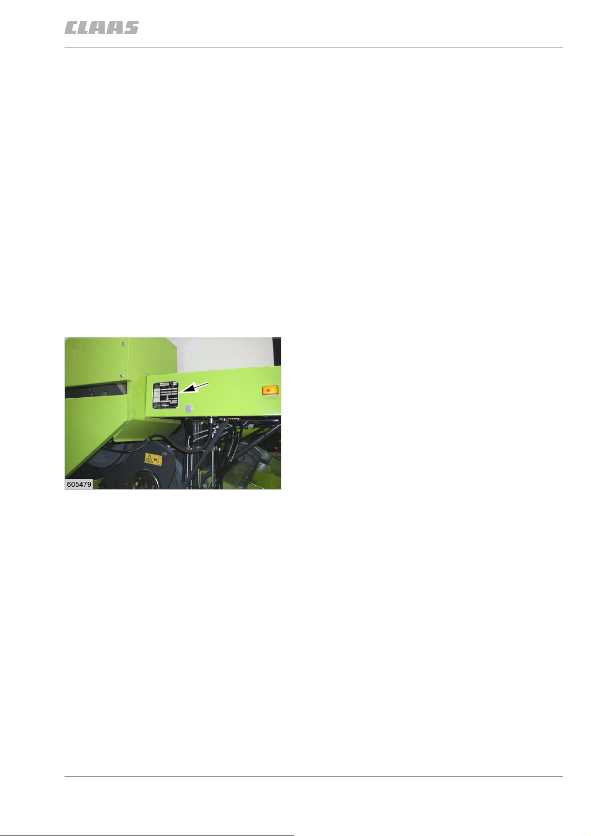
1 Introduction
1.2 Various components / Machine body
67077
1.2 Various components / Machine body
2496
1.2.1 Spare parts and technical questions
Please specify the respective identification nos. when
ordering spare parts and making technical inquiries:
• Machine
• Front attachment
•Engine
• Subassembly
and/or
• Software version / versions
This is necessary as otherwise, incorrect spare part
deliveries may result.
The identification no. can be found on the respective
type plate.
The identification no. / nos. of the software can be
found in the respective menu.
71370
1.2.2 Machine identification plate
14519
The identification plate is affixed to the right machine
side above the drive wheel.
1
00 0293 210 2 - BA DOMINATOR 150/140/130 - 12/09 23
Page 24
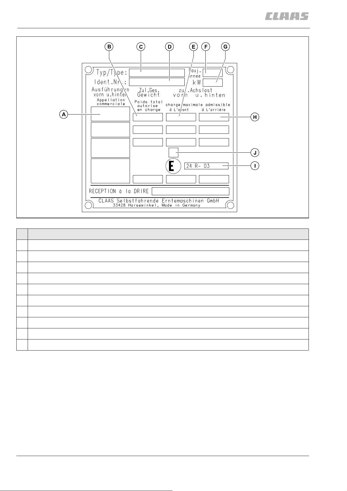
1 Introduction
1.2 Various components / Machine body
67077
Designation
A Equipment options
B Maximum admissible total weight
C Type
D Identification no. (machine serial number)
E Maximum admissible load on front axle
F Year of construction
G Rated capacity of engine (kW)
H Maximum admissible load on rear axle
I Approval no. according to ECE-R 24
J Absorption coefficient according to ECE-R 24
2415
2
24 00 0293 210 2 - BA DOMINATOR 150/140/130 - 12/09
Page 25
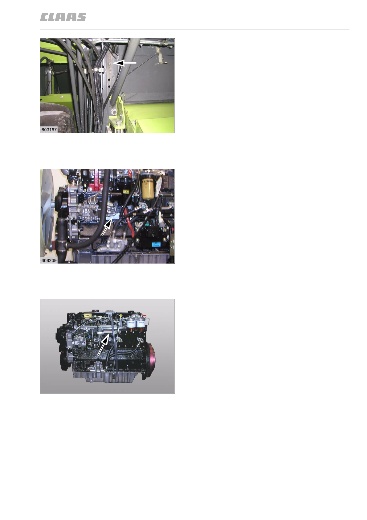
14520
1 Introduction
1.2 Various components / Machine body
67077
In addition, the identification number of the machine is
provided on the right side of the machine in the frame
under the operator's platform.
3
71381
1.2.3 Identification plate of CATERPILLAR 3056 E engine
The identification plate is located next to the injection
pump.
14521
24696
4
71383
1.2.4 Identification plate of PERKINS 1006-6T engine
The identification plate is located next to the injection
pump.
5
00 0293 210 2 - BA DOMINATOR 150/140/130 - 12/09 25
Page 26
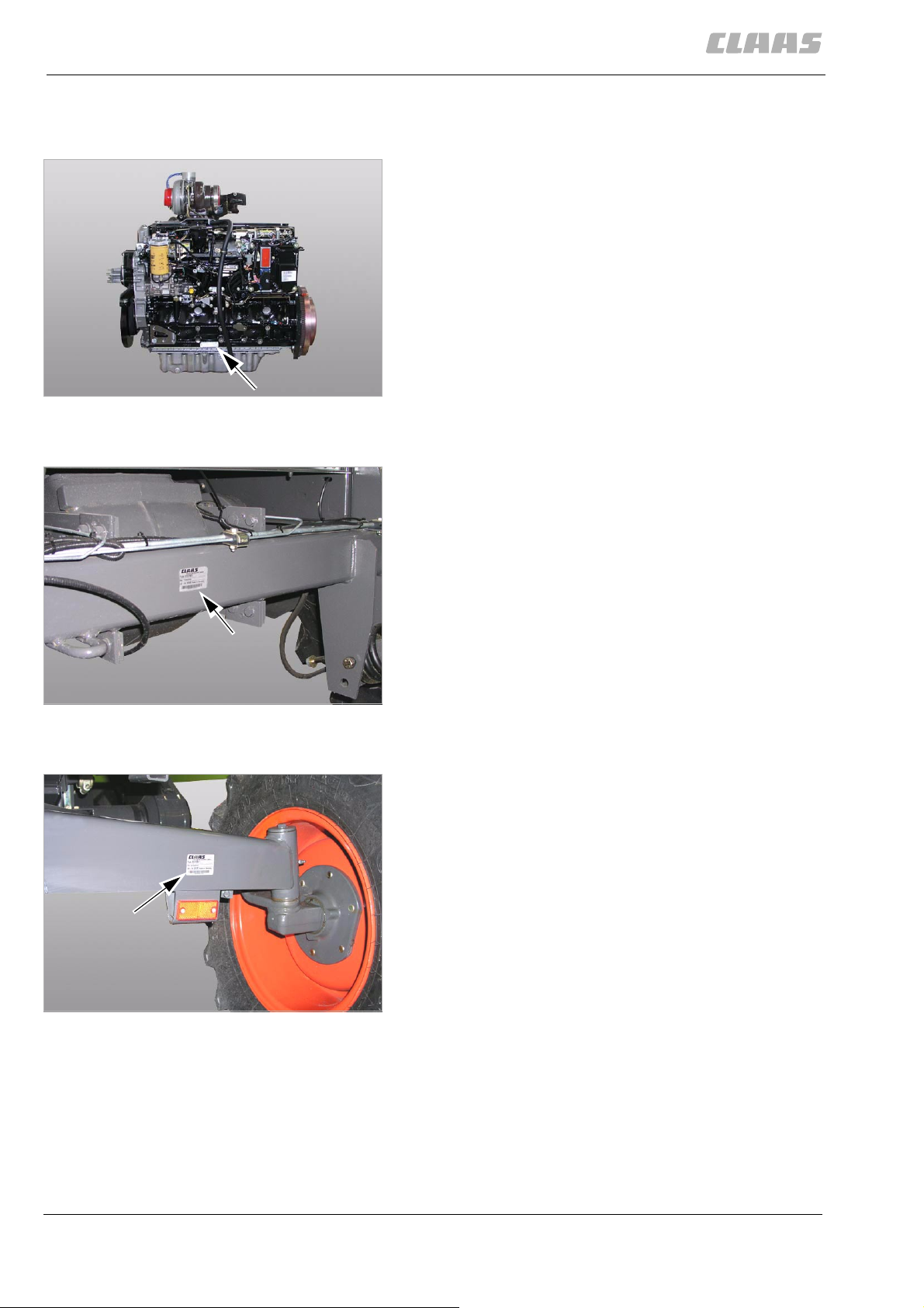
1 Introduction
1.2 Various components / Machine body
67077
71386
1.2.5 Identification plate of CATERPILLAR C6.6 engine
The identification plate is located above the oil pan.
6
27296
71607
1.2.6 Drive axle identification plate
The identification plate is affixed to the front side of the
axle.
24558
24551
7
71544
1.2.7 Rear axle identification plate
The identification plate is fixed to the axle.
8
26 00 0293 210 2 - BA DOMINATOR 150/140/130 - 12/09
Page 27
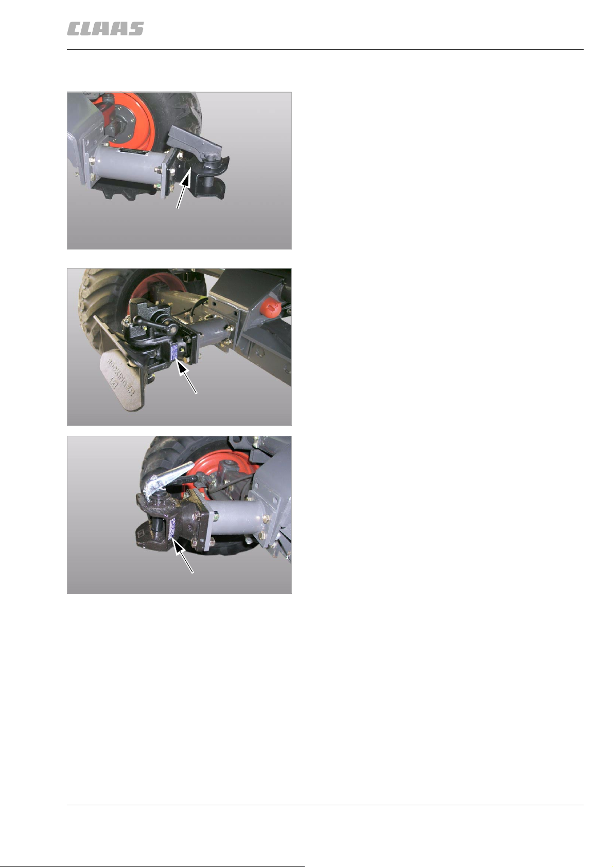
Trailer hitch type AK 64/1 B ...
1 Introduction
1.2 Various components / Machine body
67077
72052
1.2.8 Trailer hitch identification plate
The identification plate is punched into the trailer hitch.
9
24699
The identification plate is fixed to the trailer hitch.
Trailer hitch type 841 ...
Trailer hitch type 810 ...
10
36440
11
40022
00 0293 210 2 - BA DOMINATOR 150/140/130 - 12/09 27
Page 28
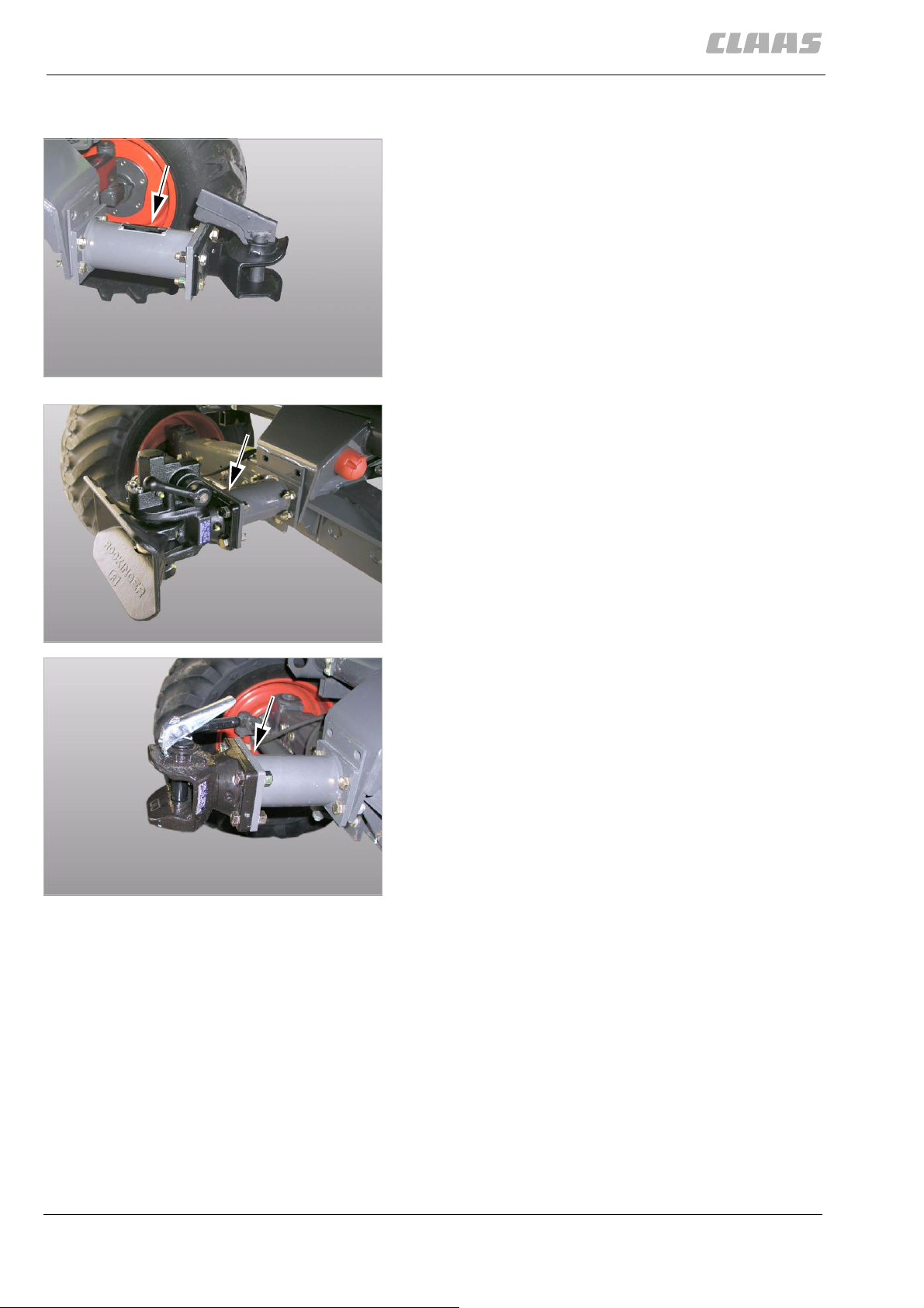
1 Introduction
1.2 Various components / Machine body
on trailer hitch type AK 64/1 B ...
67077
72056
1.2.9 Hitch block identification plate
The identification plate is fixed to the hitch block.
12
24699
The type number is punched on the hitch block.
on trailer hitch type 841 ...
on trailer hitch type 810 ...
13
36440
14
40022
28 00 0293 210 2 - BA DOMINATOR 150/140/130 - 12/09
Page 29
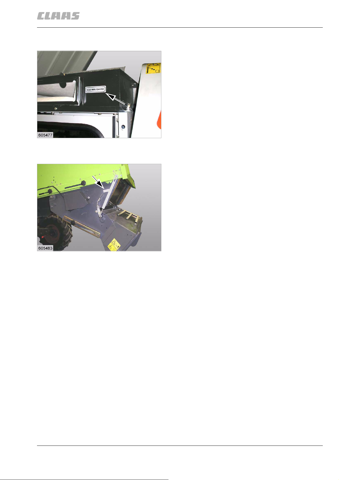
14524
1 Introduction
1.2 Various components / Machine body
67077
71389
1.2.10 Cab identification plate
The identification plate with the identification number is
fitted on the left machine side.
15
71388
1.2.11 Straw chopper identification plate
The identification plate with the identification number is
fitted on the left machine side.
14523
16
00 0293 210 2 - BA DOMINATOR 150/140/130 - 12/09 29
Page 30
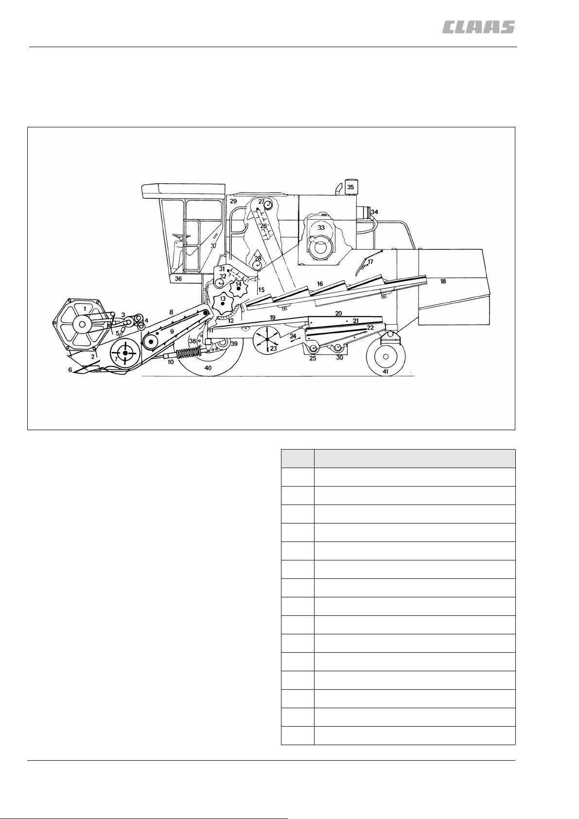
2 Sectional view of machine
2.1 Attachment parts / machine body
2 Sectional view of machine
2.1 Attachment parts / machine body
2.1.1 Machine overview
67078
72521
Designation
1 Reel
2 Reel tines
3 Reel intermediate drive
4 Reel variable speed drive
5 Reel cylinder
6 Crop lifter
7 Intake auger
8 Feed rake conveyor
9 Feed rake
10 Cutterbar cylinder
11 Stone trap
12 Concave
13 Threshing drum
19319
1
14 Impeller
15 Deflector curtain
30 00 0293 210 2 - BA DOMINATOR 150/140/130 - 12/09
Page 31

2 Sectional view of machine
2.1 Attachment parts / machine body
Designation
16 Straw walker racks
17 Crankshaft with tines
18 Rear panel
19 Preparation floor
20 Sieve pan
21 Upper sieve
22 Lower sieve
23 Cleaning fan
24 Wind board
25 Clean grain auger
26 Clean grain elevator
27 Grain tank filler auger
67078
28 Grain tank unloading auger
29 Grain tank
30 Returns auger
31 Returns elevator
32 Returns delivery auger
33 Engine
34 air filter
35 air filter intake screen
36 Operator's platform
37 Cab
38 Final drive gearbox
39 Manual gearbox
40 Traction wheels
41 Rear wheels
00 0293 210 2 - BA DOMINATOR 150/140/130 - 12/09 31
Page 32

2 Sectional view of machine
2.1 Attachment parts / machine body
67078
107718
2.1.2 Access to the workplace and maintenance areas
The operator's workplace / driver's seat (1) is in the
machine cab. The operating elements in the workplace
are used to start or shut down the machine.
The machine maintenance areas allow maintenance
or adjustment work to be performed.
Danger!
Danger of falling!
Death or serious injuries!
– Only enter areas that are designated as
workplaces or maintenance areas
and are secured by railings or similar.
– Other areas must be secured by addi-
tional rails / safety measures before they
are entered.
– Enter the workplace in the cab via the front
ladder (2) and via the maintenance area at the
1
left-hand operator's platform (3).
2
39618
3
2
3
39615
32 00 0293 210 2 - BA DOMINATOR 150/140/130 - 12/09
Page 33

2 Sectional view of machine
2.1 Attachment parts / machine body
67078
– Enter the maintenance area at the left-hand oper-
ator's platform (3) via the front ladder (2) in order
to enter the cab, clean the left-hand cab window
and adjust the mirror .
3
2
4
39615
– Enter the maintenance area at the tank
3
platform (2) via the rear ladder (1) to refuel the
machine and clean the cooling unit.
2
– Enter the maintenance area at the engine
platform (3) via the engine platform maintenance
area (2) to perform maintenance on the diesel
engine.
1
39620
5
00 0293 210 2 - BA DOMINATOR 150/140/130 - 12/09 33
Page 34

3 Safety
3.1 General Information
3 Safety
67079
3.1 General Information
45097
3.1.1 General information
The CE mark and the enclosed declaration of conformity document that the self-propelled machine
fulfils the safety regulations of the EC Machinery
Directive.
Before putting the machine into operation, read and
follow the Operator's manual and the safety
instructions!
857
3.1.2 Important information
The instructions contained in this manual should be
carefully read and observed by all persons involved
with the operation, maintenance and inspection of this
CLAAS product in order to avoid hazards.
Read in particular the sections "Safety precautions",
"Prior to initial operation" and "Prior to operation" in
Operator's manual of the machine.
The use of spare parts, accessories and ancillary
equipment other than genuine CLAAS products or
those which have been tested and approved by
CLAAS, may change the specified design characteristics of this CLAAS machine or detract from its
functional performance, with a possible adverse effect
on the active and/or passive operational safety of the
machine and its occupational safety standards (accident prevention).
CLAAS is in no way liable for any damage or personal
injury caused through the use of other than original or
approved CLAAS parts, accessories and ancillary
equipment.
106459
3.1.3 Intended use
The CLAAS combine harvester is designed exclusively
for professional use in line with the recognised regulations of agricultural practices in agricultural harvesting
of grain.
The combine harvester is a self-propelled harvesting
machine with a fitted front attachment (machine),
which is approved by the manufacturer, and is suitable
and intended for harvesting grain in fields during
travel. Grain here refers to cultivated cereal and legume crops such as wheat, rye, barley, oats, rice, rape
seed, maize, durra, soya beans and sunflowers.
34 00 0293 210 2 - BA DOMINATOR 150/140/130 - 12/09
Page 35

3 Safety
3.1 General Information
67079
The combine harvester takes the grain from the front
attachment and conveys it via a conveying unit to the
threshing and separating units. There, the grains are
separated from straw and chaff. The straw and chaff
are deposited on the field using the distribution units
behind the combine harvester. The grain is stored temporarily in the combine harvester's grain tank and then
loaded on a transport vehicle by a conveying unit.
When the combine harvester is driven on public roads,
a front attachment approved by the manufacturer can
be fitted on the front, depending on the applicable regulations, and driven with the combine harvester, or a
trailer approved by the manufacturer that is loaded
with the front attachment can be coupled to the trailer
hitch and towed.
The machine may only be used, maintained and serviced by persons who are familiar with the machine and
briefed on the hazards that may arise as a result of the
machine's functions.
Compliance with the conditions of operation, maintenance and servicing as specified in the operator's
manual and by the manufacturer also constitute
essential elements for the intended use.
The relevant accident prevention regulations, all other
generally recognised regulations on safety and occupational medicine and the road traffic regulations must
be observed by users and owners at all times.
Any use other than this is considered "unintended",
and the manufacturer is not liable for any resulting
damage. All liability in this case is borne by the user.
For specific details, you may request information on
intended use in exceptional situations from CLAAS.
106464
3.1.4 Reasonable foreseeable misuse
Use outside of intended use constitutes use not
intended by the manufacturer of the machine and
therefore amounts to misuse for the purposes of the
machinery directive. The manufacturer accepts no liability for damage resulting from this. All liability is borne
by the user.
Misuse of the CLAAS combine harvester includes:
• Use of areas and premises that are not described
in the operator's manual as workplaces
• Performance of adjustment work, cleaning work
and maintenance work against the specifications
in the operator's manual
• Performance of fault elimination and servicing
work with drives and/or the diesel engine running
• Nonobservance of warning signs on the machine
and in the operator's manual
• Performance of servicing and repair work by
untrained personnel
• Unauthorised modifications to the machine
00 0293 210 2 - BA DOMINATOR 150/140/130 - 12/09 35
Page 36

3 Safety
3.1 General Information
67079
• Attachment of non-approved additional equipment
• Use of non-original CLAAS spare parts
• Use in a stationary position
• Use to harvest goods that are not classified as
grain
• Use as a carrier vehicle for units not approved by
the manufacturer
• Use as a general towing vehicle / carrier vehicle
• Use for compacting goods and subsurfaces
• People transport
• Goods transport
2413
3.1.5 Safety and accident prevention regulations
• In addition to the instructions contained in this
operator's manual, also observe the general
safety and accident preventive regulations.
• Always check the operating and road safety of the
machine before using it.
• Always comply with local traffic regulations when
driving on public roads.
• Before starting work, familiarise yourself with all
the controls and instruments and their functions.
During work or road travel it is too late!
• Before starting the diesel engine ensure that all
guards are installed and in their correct position.
• Start the diesel engine only from the operator's
seat. Never attempt to start the diesel engine by
shortening across the starting motor terminals as
the machine may immediately start to move.
• Before starting the diesel engine and before starting up the machine:
- Ensure that there are no persons / children or
objects in the hazard area.
- Keep an eye on children!
- Sound the horn!
• Before driving off:
- Ensure that there are no persons / children or
objects in the hazard area.
- Ensure adequate visibility!
- Check if persons / children are present near the
machine!
- Keep an eye on children!
- Sound the horn!
• Never run the diesel engine in a closed building!
• Clothing worn by the operator must be close-fitting. Avoid wearing loose jackets, shirts or ties.
• Handle fuel with care. – It is highly flammable.
Never refuel the machine in the vicinity of naked
flames or sparks. Do not smoke during refuelling.
• Always stop the diesel engine and remove the
ignition key before refuelling. Fill the fuel tank outdoors. Clean up any spilled fuel immediately!
36 00 0293 210 2 - BA DOMINATOR 150/140/130 - 12/09
Page 37

3 Safety
3.1 General Information
67079
• Prevent fires by keeping the machine clean!
• Take care when handling brake fluid and
electrolytes.
Toxic and corrosive!
• Ensure an adequate safety distance from low-elevation power lines. Be careful not to damage any
broadcast or radio antennas.
• The warning and instruction signs placed on the
cutterbar provide important recommendations for
safe operating.
These instructions involve your safety – observe
them at all times.
Replace any damaged and illegible safety decals
immediately.
When parts with safety decals are replaced,
ensure that the suitable safety decals are fitted to
the new parts.
• Do not stay in the engine compartment while the
diesel engine is running.
• Ensure that the access ladder, the platform and
other access areas of the machine are always free
from oil and grease.
36687
3.1.6 General safety and accident prevention regulations for combine harvesters
• Never stand inside the range of rotation of the
unloading auger tube while the engine is running.
Do not allow any other persons to stand there as
well!
3.1.7 Prior to operation, general
• Observe the maximum permissible axle loads and
total weights.
• Before starting to drive and operate the forage
harvester, adjust the mirrors to give full vision of
the road and of the operating area behind.
• Before driving the forage harvester always check
brakes for correct function and regularly check the
level of the brake fluid. Only use the specified type
of brake fluid and change the brake fluid at the
recommended intervals.
Take care when handling brake fluid.
Toxic and corrosive!
- Dispose of used brake fluid in a way that is
harmless to the environment and in accordance
with existing anti-pollution regulations.
• The left and right brake pedals must be locked
together for transport and road travel so that both
front wheel brakes will be applied simultaneously.
• Projecting parts must be removed or adjusted to
within the normal width of the machine before driving on public roads and lanes.
• Before driving off, always check the front and rear
wheels for the correct tyre pressures!
2414
00 0293 210 2 - BA DOMINATOR 150/140/130 - 12/09 37
Page 38

3 Safety
3.1 General Information
67079
2415
3.1.8 Additional weights
Some front attachments must not be used without fitting the corresponding number of additional weights to
the machine. Please take the correct number of additional weights from this Operator's Manual.
2416
3.1.9 Transporting passengers
• Only such persons may be transported on the
instructor's seat who provide instructions regarding the machine.
• The carrying of passengers is otherwise not
permitted.
2417
3.1.10 General driving operations
• For road travel with a raised front attachment the
safety switch must be switched off.
• Never leave the operator's platform when driving.
• The grain tank / hopper must be empty when driving on public roads and lanes.
• When driving on public roads and lanes, the finger
bars, crop lifters or divider points of front attachments must be covered.
• Be particularly careful when crossing level crossings. Always stop in front of the St. Andrew's cross
when crossing the level crossing quickly and without stopping is not possible due to traffic or an
obstacle. Otherwise cross the level crossing without stopping and waiting.
• The handling of the machine is influenced e.g. by
the road surface and the attachments. Therefore,
the handling of the machine must be adapted to
existing terrain and ground conditions. Take particular care when operating or turning on a slope
and with a full grain tank / hopper. – Never take
the transmission out of gear when driving on a
slope!
• When the diesel engine is not running or in case
of power steering failure, much more effort is
required to steer the machine.
• In case of failures of the steering system and
brake system, stop the machine immediately.
Have the problems right away rectified!
3701
3.1.11 Automotive operation of combine harvester
• When travelling on public roads swing in the grain
tank unloading tube all the way.
• When travelling on public roads close the grain
tank cover.
• Existing traffic regulations must be observed.
38 00 0293 210 2 - BA DOMINATOR 150/140/130 - 12/09
Page 39

3 Safety
3.1 General Information
3.1.12 Driving operations on slopes
• When travelling downhill with a slope of more than
7%, always shift one gear down (braking effect of
diesel engine)!
• When travelling downhill in general, never exceed
the allowed max. ground speed of 20 (25) km/h.
3.1.13 Leaving the machine
• When leaving the machine, ensure that it will not
roll away (apply parking brake, wheel chocks).
Shut off the engine. Remove the ignition key and
lock the operator's cab.
• When the machine is shut down for an extended
period, turn off the battery isolating switch.
• Never leave the machine unattended as long as
the engine is still running!
• Lower the front attachments to the ground before
leaving the machine!
3.1.14 Front attachments and trailers
67079
59180
2419
2420
• Support raised front attachments securely before
doing any work underneath the units.
• Take particular care when mounting front attachments to the basic machine and when attaching a
trailer.
• Owing to their function, front attachments and
feeder mechanisms such as belts, rollers, chains,
worm gears, reels and the like cannot be completely protected by design measures; for this
reason, an adequate safety distance must be
maintained from these moving elements during
operation. These instructions also apply to all
other accessories operated on the machine.
• No person must ever be allowed between the
machine and the front attachment unless the parking brake is applied and/or the wheels are
chocked so that the vehicle can not start to move
on its own.
• Front attachments and trailers must only be
attached to the coupling devices provided for that
purpose. Observe the maximum permissible load
capacity of the trailer hitch.
• Hitch the trailer correctly to the forage harvester.
Be alert when connecting a trailer to the forage
harvester.
• Before disconnecting a front attachment always
make sure that it is stable and securely parked.
• When attaching front attachments always make
sure that the load on the existing rear axle is sufficient to maintain the forage harvester's steering
and braking capabilities.
00 0293 210 2 - BA DOMINATOR 150/140/130 - 12/09 39
Page 40

3 Safety
3.1 General Information
67079
36726
3.1.15 Crop receptacle / straw receptacle
• Under the guards of the chopping unit dangerous,
revolving cutting mechanisms are operating which
may run on after the drive has been disengaged.
Therefore, always stay a safe distance away from
the chopping unit until the unit has come to a complete standstill.
36728
3.1.16 Grain delivery
• The augers located inside the grain tank
cannot be shielded completely against accidental
contact due to their function.
• Before mounting or entering the grain tank, make
sure that no other person can restart the engine.
• Enter the grain tank only through the opening provided for this purpose.
2422
3.1.17 Air conditioner
• The air conditioning system is filled with
CFC refrigerant. CFC refrigerants must not be
allowed to escape into the atmosphere.
- Therefore, please take appropriate precautions
when working on the air conditioner.
• Maintenance and repair work may only be carried
out by specialised air conditioning system service
workshops. Refrigerant must always be sucked
out and disposed of for recycling.
37000
3.1.18 Adjustment and maintenance work
The drives on the machine will not be automatically
secured from moving after the engine has been
switched off.
Moreover, when it comes to adjustments, it may be
necessary to turn the drives.
For these reasons the following precautions should be
observed:
• Before adjustment, cleaning and maintenance
operations and before correcting malfunctions:
- Switch off the threshing mechanism.
- Switch off the front attachment.
- Switch off the grain tank unloading mechanism.
- Stop the engine.
- Disconnect the battery isolating switch.
• Before adjustment, cleaning and maintenance
operations and before correcting malfunctions at
the hydraulic system, lower the front attachment
and/or feeder unit all the way.
• Always turn off the battery isolating switch before
carrying out any electrical repairs on the machine.
40 00 0293 210 2 - BA DOMINATOR 150/140/130 - 12/09
Page 41

3 Safety
3.1 General Information
• Once the threshing unit has been switched off, the
drives will continue turning for a short period of
time. One must wait until all the drives have
stopped before carrying out any work.
• Please ensure that it is not possible for anyone to
accidentally start the machine or turn any of the
drives whilst work is being carried out.
• Escaping fluid (fuel or hydraulic oil) under high
pressure can penetrate the skin and cause serious injury. If any fluid is injected into the skin,
consult a doctor immediately as otherwise serious
infections may result.
• Repair work on the hydraulic system may only be
carried out by specialist workshops.
• Be careful when opening the radiator cap. The
radiator is under pressure when the engine is hot.
• Do not attempt to mount a tyre unless you have
the proper equipment and experience to perform
the job safely.
• Dispose of oil, fuel and filters in a way that is
harmless to the environment and in accordance
with existing anti-pollution regulations!
• Retighten the wheel nuts and wheel bolts
regularly!
3.1.19 Accumulators
67079
2424
Be especially careful when working on hydraulic systems equipped with accumulators. Hydraulic systems
with accumulators are under high pressure!
Only have qualified workshops carry out repair work on
the hydraulic system.
2425
3.1.20 Antifreeze
Antifreeze is easily inflammable!
Keep antifreeze away from children!
Vapours may cause sleepiness and a dazed feeling.
Repeated contact may cause chapped or rough skin.
The following problems may arise:
• Irritation of the eyes
• Irritation of the respiratory tract
• Headache
• Giddiness
Effects on the central nervous system in case of high
doses:
• Difficulty in breathing
• Unconsciousness
Swallowing:
• Sickness
• Vomiting
• Liver damage
00 0293 210 2 - BA DOMINATOR 150/140/130 - 12/09 41
Page 42

3 Safety
3.1 General Information
67079
Antifreeze must not come in contact with the
environment.
– Collect antifreeze in a suitable container!
– Dispose of antifreeze in a way that is harmless to
the environment and in accordance with existing
anti-pollution regulations.
2427
3.1.21 First aid measures
Inhaling:
– Make the person inhale fresh air and consult a
doctor, depending on the symptoms.
– Remove the person from the hazard area.
Eye contact:
– Thoroughly flush with water for several minutes. If
necessary, consult a doctor.
Skin contact:
– Thoroughly clean with plenty of water and soap
and remove polluted and soaked clothing immediately, consult a doctor if skin is irritated (redness
etc.).
Swallowing:
– Do not cause vomiting, consult a doctor
immediately.
107360
3.1.22 Decommissioning and disposal
When the machine (or its components) reaches the
end of its useful life and is surrendered as scrap, the
components must be disposed of in the correct manner. The regulations of the local authorities responsible
must be observed.
The operating materials in the machine require special
disposal and must not be released into the environment. More information on disposal can be obtained
from the local authorities responsible, your CLAAS
dealer or the CLAAS service department.
– Do not dispose of products marked with the
symbol (1) in your domestic waste at the end of
their service life.
1
39207
42 00 0293 210 2 - BA DOMINATOR 150/140/130 - 12/09
Page 43

7761
3.1 General Information
– Recycle used materials marked with the
symbol (2) in accordance with their labelling.
– Recycle packaging material, do not dispose of it in
domestic waste.
– Recycle plastics that are labelled with material
information, e.g. PP TV 20, do not dispose of
them in domestic waste.
– Used batteries contain hazardous substances and
must be taken back by the distributor, disposed of
correctly or delivered to a collection point. Do not
dispose of used batteries in domestic waste.
2
– Operating materials, such as oils, hydraulic fluids,
brake fluids or fuels, must be treated as hazardous waste and disposed of correctly.
– Have refrigerants disposed of only by specialist
companies with experienced personnel and the
necessary technical equipment. Refrigerants must
never be released into the atmosphere. Have
refrigerants disposed of by your CLAAS dealer.
Observe country-specific regulations.
– Follow the regulations of the local authorities
responsible.
3.1.23 Applying the feeder housing safety lock
3 Safety
67079
71723
The engaged safety lock prevents an uncontrolled
drop of the feed rake conveyor and the mounted front
attachment.
Danger!
Front attachment, reel and feeder unit may
2
drop in an uncontrolled way.
Death or serious injury.
– Fit the safety locks.
– Keep a safe distance from the hazard
1
area.
– Completely raise the feeder housing.
– Release safety lock (1) at latch (2) and fold onto
3
14528
the hydraulic ram.
– Then lower the feed rake conveyor onto the
engaged safety lock.
71724
3.1.24 Moving out the feed rake conveyor safety lock
While the combine-harvester is in operation, the cutterbar cylinder safety lock (1) must be moved up and
arrested by locking pin (2).
00 0293 210 2 - BA DOMINATOR 150/140/130 - 12/09 43
Page 44

3 Safety
3.1 General Information
1
67079
Danger!
2
Front attachment, reel and feeder unit may
drop in an uncontrolled way.
Death or serious injury.
– Fit the safety locks.
– Keep a safe distance from the hazard
area.
– Completely raise the feeder housing.
– Move cutterbar cylinder safety lock (1) up and
4
14529
attach it to locking pin (2).
71740
3.1.25 Secure the machine with wheel chocks so it will not roll away
One wheel chock (1) is provided on the machine.
1
5
14533
– Place the wheel chock (1) in front of or behind the
front wheel, depending on the slope.
– Place the wheel chocks (1) close to the drive
wheels.
Now the machine is protected against rolling away.
1
6
2732
44 00 0293 210 2 - BA DOMINATOR 150/140/130 - 12/09
Page 45

3 Safety
3.1 General Information
67079
41076
3.1.26 Securing the straw guide apron in raised position
Whenever moving the combine on public roads, raise
the straw guide apron (1) which is mounted on the rear
hood. Secure the apron in the raised position with
ropes (2). This way all taillights and reflectors will be
1
2
2
visible for all road users.
– Secure straw guide apron (1) in raised position
with ropes (2) every time before travelling on public roads.
7
14532
37012
3.1.27 Jack up the machine
– Observe the general warnings at the beginning of
the "Maintenance" chapter.
614659
Danger!
Jacking up the machine.
Death or serious injury.
– Use jack / jack stand with sufficient
1
capacity.
– Use reliable jack / jack stand.
– Use jack / jack stand on solid and level
ground.
– Apply the jack / jack stand at the position
of the machine intended for this purpose.
5298
8
The jacking points / supporting points are marked by
symbol (1) on the axles.
71772
3.1.28 Fire extinguisher
The machine is delivered ex works with one fire extinguisher (1).
– Before operating the machine, mount the fire
extinguisher (1) at the position on the machine
provided for this purpose.
F
The functionality of the fire extinguisher (s) must be
checked every two years. The date of manufacture or
the date last checked is shown on the extinguisher.
The testing intervals may differ in other countries. In
this case, the information on the fire extinguisher is
valid for the respective countries.
9
14530
Country variant for Sweden: The machine is delivered
ex works with a second fire extinguisher (1).
– Before commissioning the machine, mount the
second fire extinguisher (1) at position on the
machine provided for this purpose.
00 0293 210 2 - BA DOMINATOR 150/140/130 - 12/09 45
Page 46

3 Safety
3.1 General Information
67079
– Observe the regulations in force in the respective
countries.
71774
3.1.29 Battery isolating switch
The battery isolating switch (1) switches the power
supply of the machine on and off.
B
Switch the battery isolating switch (1) off every day
after machine use is finished and in case of
emergency.
Do not switch off the battery isolating switch (1) while
A
1
the engine is running!
Position Designation
A Power supply is OFF (by turning
anti-clockwise).
14531
10
B Power supply is ON (by turning
clockwise).
36998
3.1.30 Danger of injury due to escaping hydraulic liquid
Danger!
Liquids under high pressure.
Liquids penetrate the skin and cause serious
injury.
– Only have authorised and qualified work-
shops carry out work on the hydraulic
system.
– Check hose lines at regular intervals.
Search for leaks using a piece of wood or
11
740
cardboard.
Ensure that the oil jet will not be directed
towards your body.
– Replace any damaged hose lines.
– Replace hose lines 6 years after the date
of manufacture at the latest.
Danger!
Dealing incorrectly with injuries due to hydraulic fluids.
Death or serious injury.
Even a pinhole can result in severe injuries.
– If hydraulic fluid gets in the skin or eyes,
have the injury treated by a medical spe-
cialist immediately.
46 00 0293 210 2 - BA DOMINATOR 150/140/130 - 12/09
Page 47

3 Safety
3.1 General Information
67079
71802
3.1.31 Loading and tying down the machine
The safety decal (1) shows all permitted tie-down
points on the machine.
1
12
24611
– Suspend the machine into the devices intended
for this purpose and marked with hazard warning
signs (1).
1
13
65
– Tie down the machine with the devices intended
for this purpose and marked with safety
decals (1).
1
14
9602
00 0293 210 2 - BA DOMINATOR 150/140/130 - 12/09 47
Page 48

3 Safety
3.1 General Information
30867
15
67079
Danger!
Lifting of heavy components.
Death or serious injuries!
– Never stand in the hazard area beneath a
suspended load.
– Use only the marked slinging points and
tie-down points.
– Improper lifting or tying down may result
in machine displacement and cause injury
or damage.
– Before slinging or tying down the
machine, apply the parking brake.
– The feed rake conveyor must be fully
raised before slinging the machine.
Before persons are allowed beneath the
feed rake conveyor, its support fitted on
the lift cylinders must be applied.
– Use lift eyes and/or a carrier beam for lift-
ing the machine at the front. If no lift eyes
and/or carrier beam is available, please
contact your CLAAS dealer.
– Use only flawless and sufficiently dimen-
sioned lifting devices for lifting the
machine.
– Protect your lifting devices against sharp
corners and edges, e.g. by protectors.
48 00 0293 210 2 - BA DOMINATOR 150/140/130 - 12/09
Page 49

24680
3 Safety
3.1 General Information
67079
79364
3.1.32 Removing the lift eyes
– Remove the lift eyes and keep them for future
transport.
WARNING:
Improper transport!
Material damage to the machine.
– Lift eyes removed during the initial
machine delivery must be kept for future
transport.
16
27269
17
00 0293 210 2 - BA DOMINATOR 150/140/130 - 12/09 49
Page 50

3 Safety
3.2 Safety rules
67079
3.2 Safety rules
Before putting the machine into operation, read and
follow the Operator's manual and the safety
instructions!
76
3.2.1 Identification of warning and danger signs
All parts of this operator's manual having to do with
your safety or the safe operation of the front attachment or the machine are marked with the following
signs. Please pass on all safety precautions to any
other users of the machine as well.
Danger!
Nature and source of danger
Consequences: death or serious injury
– Countermeasures
Warning!
Nature and source of danger
Consequences: injuries
– Countermeasures
Caution!
Nature and source of danger
Consequences: material damage
– Countermeasures
Note!
Nature and source of information
Consequences: enhanced machine economy
or easy assembly
–Measures
Environment!
Nature and source of danger
Consequences: damage to the environment
– Countermeasures
50 00 0293 210 2 - BA DOMINATOR 150/140/130 - 12/09
Page 51

3 Safety
3.3 Safety decals
67079
3.3 Safety decals
859
3.3.1 General information on safety decals
The danger zones on the machine or on the front
attachment which cannot be eliminated by design or
protective measures, are identified by safety decals.
These safety decals help to alert persons to hazards
which can cause personal injury.
The safety decals consist of two components:
– Part 1 shows the risk of injury in a warning
triangle.
– Part 2 shows how injury and accidents can be pre-
vented by appropriate actions.
The pictures on the safety decals consist of generally
understandable pictograms. As far as possible, the
safety decals must be located in close proximity to the
hazardous area.
The original CLAAS safety decals are equipped with
the CLAAS part number and the date of manufacture.
The positioning and meanings of the safety decals are
explained below:
– When ordering, please use the 10-digit CLAAS
part number given ahead of every safety decal,
– the safety decal number given in ( ) shows the
correct position of the safety decals in the associ-
ated picture,
– followed by an explanation of the safety decal
graphics in text form.
Danger!
Hazard points on the machine.
Death or serious injury!
– Hazard warning signs / safety decals that
are damaged or unrecognisable must be
replaced immediately by new ones.
– When parts that have hazard warning
signs / safety decals are replaced, always
make sure to attach the relevant new hazard warning signs / safety decals to
each new part.
00 0293 210 2 - BA DOMINATOR 150/140/130 - 12/09 51
Page 52

3 Safety
3.3 Safety decals
17
67079
71832
3.3.2 Engine
00 0516 034 0 (17)
18
14569
22
14578
20
19
Do not open or remove safety shields while engine is
running.
00 0516 064 0 (22)
21
Do not open or remove safety shields while engine is
running.
52 00 0293 210 2 - BA DOMINATOR 150/140/130 - 12/09
Page 53

35
3 Safety
3.3 Safety decals
67079
00 0516 045 0 (35)
22
14577
23
Keep sufficient distance away from electrical power
lines.
39
00 0516 046 0 (39)
24
14577
25
Stay clear of hot surfaces.
00 0293 210 2 - BA DOMINATOR 150/140/130 - 12/09 53
Page 54

3 Safety
3.3 Safety decals
39
67079
00 0516 525 0 (39)
40
14578
14675
26
28
Stay clear of hot surfaces.
27
71830
3.3.3 Chassis
00 0516 047 0 (40)
40
30
Use wheel chock before machine is uncoupled or
parked.
29
14674
54 00 0293 210 2 - BA DOMINATOR 150/140/130 - 12/09
Page 55

3 Safety
3.3 Safety decals
67079
71829
3.3.4 Cab / Operator's platform
00 0515 209 1 (2)
2
32
14537
31
Carefully read operator’s manual before handling the
machine. Observe instructions and safety rules when
operating.
00 0514 946 1 (2)
2
33
14538
34
Carefully read operator’s manual before handling the
machine. Observe instructions and safety rules when
operating.
00 0293 210 2 - BA DOMINATOR 150/140/130 - 12/09 55
Page 56

3 Safety
3.3 Safety decals
67079
00 0514 895 1 (33)
33
35
14538
36
Shut off engine and remove key before performing
maintenance or repair work.
34
00 0516 044 0 (34)
37
14575
38
Do not ride on platform or ladder.
56 00 0293 210 2 - BA DOMINATOR 150/140/130 - 12/09
Page 57

53
3 Safety
3.3 Safety decals
67079
00 0516 058 0 (53)
39
14683
40
Do not operate machine unless an approved fire extinguisher is installed.
71915
3.3.5 Feeder unit
00 0516 042 0 (4)
4
41
24611
43
4
Never stand in the hazard area between the front
attachment and the machine.
42
14540
00 0293 210 2 - BA DOMINATOR 150/140/130 - 12/09 57
Page 58

3 Safety
3.3 Safety decals
13
67079
00 0516 030 0 (13)
13
44
24611
46
Secure lifting cylinder with locking device before getting in hazardous area.
15
14540
14560
45
47
00 0514 923 1 (15)
48
Do not open or remove safety shields while engine is
running.
58 00 0293 210 2 - BA DOMINATOR 150/140/130 - 12/09
Page 59

22
3 Safety
3.3 Safety decals
67079
00 0516 039 0 (22)
49
24611
50
Do not open or remove safety shields while engine is
running.
36
00 0516 043 0 (36)
51
14540
52
Avoid fluid escaping under pressure. Consult technical
manual for service procedures.
00 0293 210 2 - BA DOMINATOR 150/140/130 - 12/09 59
Page 60

3 Safety
3.3 Safety decals
67079
71916
3.3.6 Threshing mechanism
00 0514 896 1 (5)
5
56
14541
53
Touch machine parts only after they have come to a
complete halt.
5
54
14542
5
55
14543
60 00 0293 210 2 - BA DOMINATOR 150/140/130 - 12/09
Page 61

22
3 Safety
3.3 Safety decals
67079
00 0516 039 0 (22)
22
57
14673
60
Do not open or remove safety shields while engine is
running.
22
58
14675
59
14674
00 0516 064 0 (22)
22
62
14679
61
Do not open or remove safety shields while engine is
running.
00 0293 210 2 - BA DOMINATOR 150/140/130 - 12/09 61
Page 62

3 Safety
3.3 Safety decals
67079
71917
3.3.7 Separation
00 0516 039 0 (22)
22
63
14676
22
14677
65
Do not open or remove safety shields while engine is
running.
64
62 00 0293 210 2 - BA DOMINATOR 150/140/130 - 12/09
Page 63

27
3 Safety
3.3 Safety decals
67079
00 0516 054 0 (27)
27
66
14571
69
Do not open or remove safety shields while engine is
running.
27
67
14680
68
14681
00 0293 210 2 - BA DOMINATOR 150/140/130 - 12/09 63
Page 64

3 Safety
3.3 Safety decals
67079
71918
3.3.8 Crop receptacle / straw receptacle
00 0514 896 1 (5)
5
73
14557
70
Touch machine parts only after they have come to a
complete halt.
5
71
14558
5
72
14532
64 00 0293 210 2 - BA DOMINATOR 150/140/130 - 12/09
Page 65

3 Safety
3.3 Safety decals
67079
00 0514 744 1 (5)
5
74
14548
76
Touch machine parts only after they have come to a
5
complete standstill.
22
14549
14678
75
77
00 0516 064 0 (22)
78
Do not open or remove safety shields while engine is
running.
00 0293 210 2 - BA DOMINATOR 150/140/130 - 12/09 65
Page 66

3 Safety
3.3 Safety decals
67079
00 0514 897 1 (32)
32
32
32
32
14557
14558
79
80
Danger - flying objects; keep safe distance from the
82
machine as long as the engine is running.
81
14532
66 00 0293 210 2 - BA DOMINATOR 150/140/130 - 12/09
Page 67

32
32
3 Safety
3.3 Safety decals
67079
00 0514 876 1 (32)
83
14548
85
Danger - flying objects; keep safe distance from the
machine as long as the engine is running.
15
14549
14561
84
86
71938
3.3.9 Grain delivery
00 0514 923 1 (15)
87
Do not open or remove safety shields while engine is
running.
00 0293 210 2 - BA DOMINATOR 150/140/130 - 12/09 67
Page 68

3 Safety
3.3 Safety decals
67079
00 0514 901 1 (15)
15
88
14561
89
Do not open or remove safety shields while engine is
running.
16
00 0516 033 0 (16)
90
14563
16
92
Never move your hands into the rotating auger.
91
10456
68 00 0293 210 2 - BA DOMINATOR 150/140/130 - 12/09
Page 69

16
3 Safety
3.3 Safety decals
67079
00 0516 063 0 (16)
16
14564
14565
93
94
Never reach into rotating auger.
95
00 0293 210 2 - BA DOMINATOR 150/140/130 - 12/09 69
Page 70

3 Safety
3.3 Safety decals
16
67079
00 0516 063 0 (16)
16
16
14566
14567
96
97
Never reach into rotating auger.
99
98
14568
70 00 0293 210 2 - BA DOMINATOR 150/140/130 - 12/09
Page 71

24
3 Safety
3.3 Safety decals
67079
00 0516 041 0 (24)
100
14538
101
Never reach or climb into grain tank while engine is
running.
35
00 0516 045 0 (35)
102
14538
103
Keep sufficient distance away from electrical power
lines.
00 0293 210 2 - BA DOMINATOR 150/140/130 - 12/09 71
Page 72

3 Safety
3.3 Safety decals
1
67079
71956
3.3.10 Various components / Machine body
00 0514 038 2 (1)
104
14535
1
106
Use the marked points only to lift the machine. Never
stand in the hazardous area below the suspended
machine.
105
14536
00 0516 753 0 (1)
1
107
24680
109
Use only the marked points for raising the machine.
Never stand in the hazard area below the suspended
machine.
1
108
24681
72 00 0293 210 2 - BA DOMINATOR 150/140/130 - 12/09
Page 73

34
3 Safety
3.3 Safety decals
67079
00 0516 044 0 (34)
110
14576
111
Do not ride on platform or ladder.
00 0293 210 2 - BA DOMINATOR 150/140/130 - 12/09 73
Page 74

3 Safety
3.4 Safety decals
67079
3.4 Safety decals
39016
3.4.1 General instructions on safety decals
Danger!
Hazard points on the machine.
Death or serious injury!
– Hazard warning signs / safety decals that
are damaged or unrecognisable must be
replaced immediately by new ones.
– When parts that have hazard warning
signs / safety decals are replaced, always
make sure to attach the relevant new haz-
ard warning signs / safety decals to
each new part.
89475
3.4.2 Chassis
00 0516 928 0
1
Drive axle
Rear axle
113
112
9617
Observe instructions provided on the decal (1). Check
wheel nut / wheel bolt tightening torque.
00 0514 234 0
1
115
Observe instructions provided on the decal (1). Check
wheel nut / wheel bolt tightening torque.
114
30792
74 00 0293 210 2 - BA DOMINATOR 150/140/130 - 12/09
Page 75

4 Specifications
4.1 DOMINATOR 150 / 140 / 130
4 Specifications
4.1 DOMINATOR 150 / 140 / 130
4.1.1 General information
Specifications determined on a combine equipped with 6-cylinder engine, full fuel tank and 18.4 - 30 12 PR and
11.5/80 - 15.3 6 PR tyres, without cab.
4.1.2 CATERPILLAR C6.6 engine
Designation CAT C6.6 DOMINATOR
67080
72071
72072
150
140
130
Engine manufacturer • ••CATERPILLAR
Engine type •
Exhaust stage •
Cubic capacity •
Maximum no-load speed •
Rated speed •
Minimum no-load speed •
Reduced speed in third gear at 20 km/h •
Reduced speed in third gear at 25 km/h •
Speed in third gear at 25 km/h
Engine power at rated speed •
Power (EEC 80/1296) •
••CAT C6.6
••Exhaust gas category 3a
••6.6 litres
••2290
+10/-40
rpm
••2200 ± 10 rpm
••1200 ± 20 rpm
• 1580
• 1800
• 1970
• 2290
+20/-30
+20/-30
+20/-30
+10/-40
rpm
rpm
rpm
rpm
••2200 ± 10 rpm
116 (158), kW (hp)
• 100 (136), kW (hp)
• 100 (136), kW (hp)
Power (ECE R 24) •
110 (150), kW (hp)
• 91 (124), kW (hp)
• 94 (128), kW (hp)
Alternator •
Fuel tank capacity •
••100 A / 12 V
••280 litres
• 200 litres
00 0293 210 2 - BA DOMINATOR 150/140/130 - 12/09 75
Page 76

4 Specifications
4.1 DOMINATOR 150 / 140 / 130
4.1.3 CATERPILLAR 3056E engine
Designation CAT 3056E DOMINATOR
150
140
Engine manufacturer • ••CATERPILLAR
130
67080
72119
Engine type •
Exhaust stage •
Cubic capacity •
Maximum no-load speed •
Rated speed •
Minimum no-load speed •
Reduced speed in third gear at 20 km/h •
Reduced speed in third gear at 25 km/h •
Speed in third gear at 25 km/h
Engine power at rated speed •
Power (EEC 80/1296) •
Power (ECE R 24) •
••CAT 3056E
••Exhaust gas category 2
••5.9 litres
••2290
+10/-40
rpm
••2200 ± 10 rpm
••1200 ± 20 rpm
• 1580
• 1800
• 1970
• 2290
+20/-30
+20/-30
+20/-30
+10/-40
rpm
rpm
rpm
rpm
••2200 ± 10 rpm
112 (152), kW (hp)
• 97 (132), kW (hp)
• 97 (132), kW (hp)
104 (141), kW (hp)
• 89 (121), kW (hp)
• 92 (125), kW (hp)
Alternator •
Fuel tank capacity •
••85 A / 12 V
••280 litres
• 200 litres
4.1.4 Perkins 1006-T6 engine
Designation Perkins 1006-T6 DOMINATOR
150
140
Engine manufacturer • Perkins
Engine type
Exhaust stage
Cubic capacity
Maximum no-load speed
Rated speed
Minimum no-load speed
130
• Perkins 1006-T6
• Exhaust gas category 0
• 6 litres
• 2290
• 2200 ± 10 rpm
• 1200 ± 20 rpm
+10/-40
72121
rpm
76 00 0293 210 2 - BA DOMINATOR 150/140/130 - 12/09
Page 77

Designation Perkins 1006-T6 DOMINATOR
4 Specifications
4.1 DOMINATOR 150 / 140 / 130
67080
150
140
130
Speed in third gear at 25 km/h • 2290
Engine power at rated speed
Power (EEC 80/1296)
Power (ECE R 24)
Alternator
Fuel tank capacity
• 2200 ± 10 rpm
• 112 (152), kW (hp)
• 104 (141), kW (hp)
• 85 A / 12 V
• 200 litres
4.1.5 Chassis
Designation DOMINATOR
150
Ground drive
•
140
130
Hydrostatic,
•
actuated by a lever
Mechanical,
•
variable-speed drive, hydraulically
controlled
+10/-40
rpm
72156
Clutch
Manual gearbox
Forward ground speed
(with 18.4-3012PR tyres)
Forward ground speed
(with 18.4-3012PR tyres)
Reverse ground speed
• dry single disc clutch
Three gears each for forward and
reverse travel
•
•
1st and 2nd gears: fieldwork gear
3rd gear: road gear
three forward, one reverse gear
•
1st and 2nd gears: fieldwork gear
3rd gear: road gear
1st gear from 0 to 7.4 km/h
•
•
2nd gear from 0 to 13.9 km/h
3rd gear from 0 to 20.0 km/h
(from0to25.0km/h)
1st gear from 1.9 to 4.9 km/h
•
2nd gear from 4.7 to 12.9 km/h
3rd gear from 7.6 to 20.0 km/h
•
•
Approx. 70% of the forward ground
speed.
• Reverse gear from 3.6 to 9.9 km/h
Differences in ground speed for different tyre
sizes.
Front wheel drive •
•
••
••Final drives running in oil
± 10%.
00 0293 210 2 - BA DOMINATOR 150/140/130 - 12/09 77
Page 78

4 Specifications
4.1 DOMINATOR 150 / 140 / 130
4.1.6 Tyre pressures
67080
72211
24769
1
24770
78 00 0293 210 2 - BA DOMINATOR 150/140/130 - 12/09
2
Page 79

4 Specifications
4.1 DOMINATOR 150 / 140 / 130
67080
24771
3
00 0293 210 2 - BA DOMINATOR 150/140/130 - 12/09 79
Page 80

4 Specifications
4.1 DOMINATOR 150 / 140 / 130
4.1.7 Chassis track width
SP Inside spacer
FW Flange width
A Width between the tyres
B Track width
C Width over tyres
Tyres DOMINATOR SP
67080
72224
(mm)FW(mm)A(mm)B(mm)C(mm)
150
140
130
Drive axle
00 0723 790 5
18.4-30 12PR R1 TT KB • •• 2283 1679 2183 2687
23.1-26 12PR R1 KB F20 •
23.1-26 12PR R1 KB F16 •
23.1-26 R2 Dia •
620/75 R26 16EA8 F20 •
28LR26 (750/65 R26) 155A8 •
750/65R26)166A8TLMi •
Steel half-tracks
LA-P Rear axle position,
1 = bottom hole
2 = top hole
3 = rear axle rise
FW Flange width
A Width between the tyres
B Track width
•• 2283 1771 2405 3039
•• 2283 1660 2243 2826
•• 2283 1771 2405 3039
•• 2283 1775 2405 3035
•• 2283 1643 2413 3183
•• 2283 1686 2413 3140
• 2283 1993 2693 3393
C Width over tyres
Tyres DOMINATOR LA-P FW
(mm)A(mm)B(mm)C(mm)
150
Rear axle
00 0637 630 2
140
11.5/80-15.3 IMP • •• 1 2040 1790 2080 2370
12.5/80-18 IMP (320/80-18) •
•• 2 2040 1790 2110 2430
130
80 00 0293 210 2 - BA DOMINATOR 150/140/130 - 12/09
Page 81

LA-P Rear axle position,
1 = bottom hole
2 = top hole
3 = rear axle rise
FW Flange width
A Width between the tyres
B Track width
C Width over tyres
Tyres DOMINATOR LA-P FW
4 Specifications
4.1 DOMINATOR 150 / 140 / 130
67080
(mm)A(mm)B(mm)C(mm)
150
140
130
Rear axle
00 0649 950 1
Rear axle
11.5/80-15.3 IMP • •• 1 2291 2041 2331 2621
•
•
12.5/80-18 IMP (320/80-18) •
•
•
14.5/75-20 IMP(360/80-20) •
•
•• 1 2491 2241 2531 2821
•• 1 2691 2441 2731 3021
•• 2 2291 2041 2361 2681
•• 2 2491 2241 2561 2881
•• 2 2691 2441 2761 3081
•• 2 2291 1986 2351 2716
•• 2 2491 2186 2551 2916
9.5-24 R1
00 0770 350 1
4.1.8 Brake
Designation DOMINATOR
150
Foot brake
•
140
••
•
3 2391 2200 2441 2682
72235
130
Hydraulically actuated brakes, also
designed to work as independent
brakes
Parking brake •
••mechanical, independent of foot brake
72237
4.1.9 Steering
Designation DOMINATOR
150
Steering, type • ••hydrostatic
00 0293 210 2 - BA DOMINATOR 150/140/130 - 12/09 81
140
130
Page 82

4 Specifications
4.1 DOMINATOR 150 / 140 / 130
4.1.10 Electric system / Electronics
Designation DOMINATOR
150
140
130
Battery • ••12 volts, 110 Ah
4.1.11 Cab / Operator's platform
Designation DOMINATOR
150
140
130
67080
72245
72252
A-valuated equivalent permanent sound pressure level
•
••
77 - 79 dB (A)*
* This A-valuated equivalent permanent sound pressure level has been determined in the cab (door and window
closed) when the machine is in operating mode during intended use. The permanent sound pressure level is
influenced by various external factors. These factors, such as crop, setting and load from the operator, environment on the field and weather conditions, cannot be influenced by the machine manufacturer.
2
Total vibration value (vibrations), to which the
upper limb dimensions are subjected.
Effective value (vibrations), of the weighted
acceleration to which the entire body is
•
•
••
••
≤ 2.5 m/s
≤ 0.5 m/s
**
2
**
subjected.
** Measuring methods (vibrations), •
** Measurement inaccuracy (vibrations), •
••EN 1032:2003
••EN 12096:1997
** The vibrations were determined in operating mode during intended use. The vibrations are influenced by various external factors. These factors, such as crop, setting and load from the operator, environment on the field
and weather conditions, cannot be influenced by the machine manufacturer.
4.1.12 Intake
72248
Designation DOMINATOR
150
Cutterbar widths
Feed rake conveyor •
140
•
••
• 5.18 m (country-specific)
•
•
••Feeder chain
130
3.05 m, 3.66 m, 3.96 m, 4.27 m,
4.57 m
6.09 m (country-specific)
82 00 0293 210 2 - BA DOMINATOR 150/140/130 - 12/09
Page 83

4.1.13 Threshing mechanism
Designation DOMINATOR
4 Specifications
4.1 DOMINATOR 150 / 140 / 130
67080
72250
150
140
130
Threshing drum diameter • ••450 mm
Threshing drum width •
Threshing drum speed •
Threshing drum chain drive (optional equipment) •
Threshing drum rasp bars •
Stone trap •
Main concave, continuous concave
(optional equipment)
- Grain •
- Grain •
- Maize •
- Rice
Main concave, multicrop concave
(optional equipment)
- Grain •
•
•
•
••1060 mm
••650 - 1500 rpm
••500 - 1400 rpm (optional equipment)
••304 rpm, 432 rpm, 556 rpm, 268 rpm,
••6
••
••
continuous concave
••Wire concave N10 **
••Wire concave N12 **
••Wire concave N18 **
• Spike tooth concave **
••
3 concave segments
••Wire concave N10 ***
- Grain •
- Maize •
Main concave contact angle •
Disawner bars
Threshing concave adjuster •
•
•
••Sheet-metal concave (10 x 38)***
••Sheet-metal concave (19 x 40)***
••117°
••
••
2 one-piece disawner bars
(optional equipment)
2 three-piece disawner bars
(optional equipment)
••1 lever (proportional from the cab)
** = continuous concave, *** = multicrop concave with 3 concave segments
4.1.14 Separation
Designation DOMINATOR
150
Straw walker racks (number) • ••4
Speed of straw walker shafts •
Straw walker area •
Straw walker separating area • ••4.80 m
140
130
••220 ± 5 rpm
••4.13 m
72293
2
2
Intensive separators (number) • ••4
00 0293 210 2 - BA DOMINATOR 150/140/130 - 12/09 83
Page 84

4 Specifications
4.1 DOMINATOR 150 / 140 / 130
4.1.15 Cleaning unit
Designation DOMINATOR
150
140
Fan • ••paddle-type cleaning fan
130
67080
72296
Fan adjustment •
Preparation floor •
3-D cleaning system •
Sieve separating area •
••mechanical
••removable
••(optional equipment)
••3.00 m
2
4.1.16 Grain delivery
Designation DOMINATOR
150
140
130
Returns • ••returned to threshing drum
Grain tank capacity
basis for calculation in t = litre weight of 780 g/l
•
••
4000 litres (approx. 3.1 metric tons of
wheat)
3200 litres (approx. 2.5 metric tons of
wheat)
4.1.17 Attachment parts / machine body dimensions
72299
72313
Designation DOMINATOR
150
B Width of the body (machine width with
tyres – see chassis wheel track)
•
140
••
130
3000 mm
84 00 0293 210 2 - BA DOMINATOR 150/140/130 - 12/09
Page 85

Designation DOMINATOR
4 Specifications
4.1 DOMINATOR 150 / 140 / 130
67080
H Height, up to top edge of air filter suction
150
• • 3850 mm*
140
screen, grain tank closed
Height up to upper edge of grain tank,
•
• 4100 mm*
open
* Height determined with 18.4 - 30 12 PR and 11.5/80 - 15.3 6 PR tyres
L Length, feed rake conveyor to tailgate •
Length, feed rake conveyor to straw chopper protective cover
Length, feed rake conveyor to straw
spreader safety frame
Length, feed rake conveyor up to straw
collector
Wheel base •
•
•
•
••7200 mm**
••
••
••
••3335 mm
Ground clearance (up to elevator boot)
Deviations of up to ±50 mm possible,
•
••
depending on the tyre manufacturer.
130
• 3840 mm*
• 4080 mm*
7400 mm**
8020 mm**
8050 mm**
435 mm**
Left turning circle diameter DIN 70020 •
Right turning circle diameter DIN 70020 •
••15150 mm
••15250 mm
** (Height of bottom edge of feed rake conveyor 500 mm)
00 0293 210 2 - BA DOMINATOR 150/140/130 - 12/09 85
Page 86

4 Specifications
4.1 DOMINATOR 150 / 140 / 130
4.1.18 Attachment parts / machine body weights
Designation DOMINATOR
150
140
Empty weight * • 7330 kg
••7250 kg
130
67080
72306
Chopper weight •
Straw spreader •
Straw collector •
••+ 290 kg
••+ 97 kg
••+ 235 kg
* Empty weight without cutterbar, chopper and chaff spreader, with full fuel tank
86 00 0293 210 2 - BA DOMINATOR 150/140/130 - 12/09
Page 87

5 Prior to initial operation
5 Prior to initial operation
5.1 General Information
67081
5.1 General Information
37391
5.1.1 General warnings Prior to initial operation
In the following sections of this chapter, a procedure
instruction refers to the following general warnings.
Danger!
Always stop the engine before carrying out
any work on the machine.
Moving machine parts and / or unexpected
machine movement.
Death or serious injury.
– Diesel engine OFF.
– Apply parking brake.
– Remove the ignition key.
– Remove key of battery isolating
switch.
– Wait for machine parts which run on have
come to a complete halt.
– Secure machine by wheel chocks.
– Ensure that the machine cannot be
started by any third persons.
Danger!
The front attachment, reel and feeder unit may
drop uncontrolled.
Death or serious injuries!
– Apply safety locks.
– Keep a safe distance from the hazard
area.
5.1.2 Initial operation check list
The following must be done before putting the
machine into operation.
– Complete all necessary items on the checklist for
daily putting the machine into operation.
– Observe instructions for loading and tying down
the machine.
– After sea transport or road transport in winter road
conditions, clean the machine to protect it from
salt damage.
Engine
– Check the correct seat of air filter.
– Check the diesel engine oil level.
– Check the radiator coolant level.
79390
00 0293 210 2 - BA DOMINATOR 150/140/130 - 12/09 87
Page 88

5 Prior to initial operation
5.1 General Information
67081
Chassis
– Fit the wheels.
– Check the tyre pressure and correct if necessary.
– Check condition and permissibility of tyres.
– If necessary adjust the rear axles / rear wheel
drive axles from transport position to working
position.
– If necessary adjust the wheel track for the given
tyres.
– Check tightening values of wheel fixing elements
and correct if necessary.
– Check oil level in all gearboxes and refill if
necessary.
Brake
– Check brake fluid level and top up if required.
Drives
– Check all belt tensions and adjust if necessary.
– Check all safety guards and put them into their
correct position, if required.
– Check oil level in all gearboxes and top up if
necessary.
Hydraulic system
– Check hydraulic oil level and tightness of hydrau-
lic system.
Electrical / electronic equipment
– Fill and charge battery, if required.
– Install fan / air conditioner fuse.
– If necessary, install side lights in case of excess
width.
Intake
– Remove the lift eyes.
– Fit mounting plates.
– Check the front attachment float springs.
– Align the coupling lugs (machines without Auto-
Contour)
Separation
– Remove the lift eyes.
Grain delivery
– Close the service aperture on the grain tank
unloading tube.
– Install the grain tank safety device.
– Putting the air conditioner into operation (with
Sanden compressor)
88 00 0293 210 2 - BA DOMINATOR 150/140/130 - 12/09
Page 89

5 Prior to initial operation
5.2 Chassis
67081
5.2 Chassis
89352
5.2.1 Removing / installing the wheels
– Observe the general warnings at the beginning of
the Prior to initial operation chapter.
– Jack up the machine.
– Remove / install wheel.
Ensure that large tyres cannot tip over, if neces-
sary use a carriage.
– After fitting the wheel, tighten all wheel nuts /
wheel bolts (1) to the specified tightening torque
as instructed.
1
9617
27215
1
79223
5.2.2 Overview of rear axle
Either one or several different types of rear axles are
available.
The part number for identifying the rear axle is provided on the identification plate of the axle.
Rear axle
00 0770 350 1
2
00 0293 210 2 - BA DOMINATOR 150/140/130 - 12/09 89
Page 90

5 Prior to initial operation
5.2 Chassis
67081
Rear axle
00 0649 950 1
3
19471
79317
5.2.3 Converting the rear axle from transport to working position
– Observe the general warnings at the beginning of
the Prior to initial operation chapter.
The following installation steps must be carried out,
depending on the tyres used on the rear axles
00 0637 630 2, 00 0649 950 1 and 00 0770 350 1:
See table of rear axle positions.
Rear axle position
LA-P Rear axle position,
1 = bottom hole,
2 = top hole,
3 = rear axle rise (rice)
FW Flange width
Tyres DOMINATOR LA-P FW
Rear axle
00 0637 630 2
Rear axle
11.5/80-15.3 IMP • •• 12040
12.5/80-18 IMP (320/80-18) •
11.5/80-15.3 IMP •
00 0649 950 1
12.5/80-18 IMP (320/80-18) •
•
•
•
150
140
130
•• 22040
•• 12291
•• 12491
•• 12691
•• 22291
•• 22491
(mm)
Rear axle
•
14.5/75-20 IMP(360/80-20) •
•
9.5-24 R1
•• 22691
•• 22291
•• 22491
32391
•
00 0770 350 1
90 00 0293 210 2 - BA DOMINATOR 150/140/130 - 12/09
Page 91

5 Prior to initial operation
5.2 Chassis
WARNING:
The tyres may collide with the vehicle body.
Damage to tyres and vehicle body.
– Adjust track width to the tyres used.
– Adjust the rear axle position of the central
axle pivot pin with the axle. See table of
rear axle positions
Danger!
Jacking up the machine.
Death or serious injury.
– Use jack / jack stand with sufficient
capacity.
– Use reliable jack / jack stand.
– Use jack / jack stand on solid and level
ground.
– Apply the jack / jack stand at the position
of the machine intended for this purpose.
67081
– Suspend the machine in the lift eyes at the rear
and lift it (see loading and tying down the
2
machine) until the rear axle wheels have only
slight ground contact.
– Securely underpin axle against lowering and tip-
ping over.
1
– Unscrew flat bar (2) and pull out pin (1).
– Raise or lower machine.
– Insert pin (1) into the bottom or top hole and bolt
down flat bar (2). For rear axle rise (rice) see rice
threshing equipment.
4
27234
– If necessary, adjust rear wheel drive
axle 00 0649 950 1 wheel track.
79261
5.2.4 Rear axle 00 0649 950 1 – Adjusting the
track width
– Observe the general warnings at the beginning of
the Prior to initial operation chapter.
Warning:
The tyres may collide with the vehicle body.
Damage to tyres and vehicle body.
– Adjust track width to the tyres used.
The track width depends on the flange width (F) to be
set and on the tyres.
The axle can be set to three different flange widths.
00 0293 210 2 - BA DOMINATOR 150/140/130 - 12/09 91
Page 92

5 Prior to initial operation
5.2 Chassis
67081
Danger!
1
Jacking up the machine.
Death or serious injury.
3
– Use jack / jack stand with sufficient
capacity.
– Use reliable jack / jack stand.
– Use jack / jack stand on solid and level
ground.
2
5
19471
– Jack up the machine a little at the rear until the
– Apply the jack / jack stand at the position
of the machine intended for this purpose.
rear axle wheels only have slight ground
contact.
– Remove the right-hand ball joint of the track rod.
– Remove steering cylinder mounting bracket (1)
from the axle body.
– Slacken off the clamping bolts (2) on both sides.
– Unscrew mounting bolts (3) on both sides.
– Slide the adjustable axle sections in or out to
obtain the desired track width (2300 mm, 2500
mm, 2700 mm). Install mounting bolts (3), but do
not tighten them at this time.
– Tighten clamping bolts (2) first, then tighten
mounting bolts (3).
– Bolt down mounting bracket (1) in the correspond-
ing tapped holes.
– Set the wheels to zero toe-in by adjusting the
right-hand ball joint on the track rod. In order to
obtain accurate measurements, measure from the
inside edges of the rim, where the beading of the
tyres rests. Secure the track rod. Use new self-
locking nuts. Tightening torque = 140 Nm
92 00 0293 210 2 - BA DOMINATOR 150/140/130 - 12/09
Page 93

5 Prior to initial operation
5.3 Hitch
67081
5.3 Hitch
102219
5.3.1 Installing the trailer hitch (accessories)
– Observe the general warnings at the beginning of
the Prior to initial operation chapter.
1
Danger!
Improper mounting of the trailer hitch.
2
Trailer hitch type AK 64/1 B ...
3
Trailer hitch type 841 ...
3
Death or serious injuries!
– Note the prescribed tightening torque for
the trailer hitch.
4
6
24699
– Bolt down hitch block (1) with bolts (2).
The bolt heads must point to the rear.
Tightening torque M14 = 133 Nm
– Bolt down trailer hitch (3) with bolts (4). The bolt
1
heads point to the rear.
Tightening torque M16 = 207 Nm
– If required, bolt down the bracket for the cutterbar
trailer brake system tear-off cord to bolt (4).
2
4
7
36440
1
3
4
2
8
Trailer hitch type 810 ...
40022
00 0293 210 2 - BA DOMINATOR 150/140/130 - 12/09 93
Page 94

5 Prior to initial operation
5.4 Electrical / electronic equipment
67081
5.4 Electrical / electronic equipment
59400
5.4.1 Installing the fan / air conditioner fuse
The fan / air conditioner fuse is enclosed as a pack
joint (cab) on machines with an air conditioner in order
to prevent compressor damage.
– Install fan / air conditioner fuse.
– Put the air conditioner into operation.
94 00 0293 210 2 - BA DOMINATOR 150/140/130 - 12/09
Page 95

5 Prior to initial operation
5.5 Feeder unit
67081
5.5 Feeder unit
79358
5.5.1 Fitting / adjusting the mounting plates
– Observe the general warnings at the beginning of
the Prior to initial operation chapter.
DANGER!
The front attachment is not sufficiently
secured.
Death or serious injury.
– Comply precisely with procedure
instructions.
– Check the safe locking of the front
attachment.
– Bolt down mounting plate (4) hand-tight on both
sides of the machine.
3
4
B
2
A
9
19523
– Fit front attachment.
– Pull out cotter pin at position (A).
– Slide lock pin (2) up into the feeder unit opening of
the machine, using lever (3).
– Secure lever (3) in position (B), using the cotter
pin.
– Slacken off mounting plate (4) and slide it as
closely to the lock pin (2) as possible. Bolt down
mounting plate (4).
89422
5.5.2 Aligning the coupling pin
F
The front attachment must be parallel with the drive
axle of the machine. To achieve this, the coupling pins
must be aligned.
– Drive the machine with the front attachment fitted
on a flat and level surface.
– Check the alignment. The finger bar must be par-
allel with the ground while the machine stands on
a flat and level surface.
– If necessary, put down the front attachment.
– Slacken off coupling pins (1) and raise or lower
the pins so that the finger bar is parallel with the
10
19525
ground on a flat and level surface.
00 0293 210 2 - BA DOMINATOR 150/140/130 - 12/09 95
Page 96

5 Prior to initial operation
5.5 Feeder unit
1
3
Number of cutterbar cylinders
Dominator 130 / 140 / 150
67081
79492
5.5.3 Checking the front attachment cylinders
– Observe the general warnings at the beginning of
the Prior to initial operation chapter.
The front attachment cylinders (1) are fitted ex works
to suit the ordered front attachment width. When
changing the front attachment width at a later date, the
cylinder diameter must be checked / adapted.
11
19598
Diameter
Cutterbar cylinder
mm
Cutterbar 3.05 m – 4.57 m 45 2
Cutterbar 5.18 m – 6.09 m 55 2
Cutterbar cylinder
Number
96 00 0293 210 2 - BA DOMINATOR 150/140/130 - 12/09
Page 97

5 Prior to initial operation
5.5 Feeder unit
5.5.4 Checking the cutterbar float springs
The cutterbar float springs (1) are pre-set ex works.
The cutterbar float springs (1) must be checked and
adjusted with the front attachment fitted.
67081
73259
1
– Fit the front attachment.
– Fit the crop dividers.
– Lower the cutterbar until the skids are about 100
mm above the ground.
3
12
19598
2
13
19599
The distance (Y) between the coupling pin cylinder
plate and the nuts should be 5 mm.
– Adjust the cutterbar float springs if required.
- To do this, adjust the cutterbar float springs
accordingly at the socket head bolts (2).
– Observe the general warnings at the beginning of
the Prior to initial operation chapter.
2
Y
Danger!
Bolts may break when tilting the spring plates.
14
19600
Death or serious injuries!
– Ensure that the tilted position of the
spring plate near the bolt pitch circle
diameter may be 1mm max.
– Grease bolt threads.
– Now turn the bolts in or out by
3 revolutions each (5 mm) max., one
after the other.
Adjusting the bolts (2):
Increasing the distance Turn bolts in
Reducing the distance Turn bolts out
00 0293 210 2 - BA DOMINATOR 150/140/130 - 12/09 97
Page 98

5 Prior to initial operation
5.5 Feeder unit
67081
– Check adjustment after changing the front attach-
ment and readjust if required.
98 00 0293 210 2 - BA DOMINATOR 150/140/130 - 12/09
Page 99

5 Prior to initial operation
5.6 Grain delivery
67081
5.6 Grain delivery
79443
5.6.1 Closing the service aperture on the grain tank unloading tube
– Observe the general warnings at the beginning of
the Prior to initial operation chapter.
The service aperture on the grain tank unloading tube
serves as a water drain, e.g. for cleaning.
Warning!
Sharp edges and pointed machine parts.
1
Slight injuries.
– Do not touch sharp edges of the auger
flights.
15
19660
– Wear safety gloves.
Note!
Open service aperture.
Trickling losses.
– Close the service aperture and screw in
bolt (1).
– Close the service aperture and screw in bolt (1)
before putting the machine into operation for the
first time.
83027
5.6.2 Installing the grain tank safety device
– Observe the general warnings at the beginning of
the Prior to initial operation chapter.
Danger!
Danger of falling!
2
2
Death or serious injuries!
– Arrange for additional safety precautions.
– Only enter areas protected by railings.
1
– Areas originally without railings must be
protected by additional railings.
16
10456
– Open the grain tank cover and fold it open to the
rear as far as possible.
– Install safety device (1) into the rails (2).
00 0293 210 2 - BA DOMINATOR 150/140/130 - 12/09 99
Page 100

5 Prior to initial operation
5.6 Grain delivery
67081
Danger!
Missing or damaged safety devices.
Death or serious injury.
– Fit safety devices before putting the
machine into operation.
– Check function of safety devices at regu-
lar intervals.
– Replace worn or damaged safety devices
by new ones.
100 00 0293 210 2 - BA DOMINATOR 150/140/130 - 12/09
 Loading...