

Page 1

DISCO 8500C (Tractor)
DISCO 8500C-6, -8
(until serial no.: 652 01278)
DISCO, CORTO, VOLTO, LINER
(JAGUAR)
Technical Systems
Page 2

Hydraulic / Electric System JAGUAR 8550C TIC
10/04
Page 3

TIC JAGUAR 8550C Hydraulic / Electric System
Chapter 1 JAGUAR 8500 C,
JAGUAR 8500 C- 6,
JAGUAR 8500 C- 8
2 DISCO 8500 C
3 CORTO 8100 F/T
4 LINER 3000,
LINER 1550 TWIN,
LINER 650 TWIN
5 VOLTO 1050,
VOLTO 870H
6 DISCO 3000TC, TRC, AS, FG
CORTO 3100, 300, 252, 250
10/04
Page 4

Hydraulic / Electric System JAGUAR 8550C TIC
10/04
Page 5

TIC JAGUAR 8550C Hydraulic / Electric System
Hydraulic System...................................................................................................................................2
1.0
1.1
JAGUAR 8500C-6, C-8 hydraulic circuit diagram................................................................................2
1.2 Function ...............................................................................................................................................8
Electric system JAGUAR 8500C, CISCO 8500C-6, -8.......................................................................14
2.0
2.1
Electric circuit diagram.......................................................................................................................14
2.2 Function .............................................................................................................................................16
2.3 Central terminal compartment............................................................................................................20
3.0 Installation information.......................................................................................................................24
3.1
Timing of drives..................................................................................................................................24
3.2 Installation of pinion units...................................................................................................................25
3.3 Safety module ....................................................................................................................................26
3.4 Tightening torques .............................................................................................................................27
4.0 Drive diagram.......................................................................................................................................28
Attention The description of the Jaguar 8500C also applies to
- Disco 8500C-6
- Disco 8500C-8
The only exception is: The Reed switch (75) does not exist on the
Disco 8599C-6.
10/04 1-1
Page 6

Hydraulic / Electric System JAGUAR 8550C TIC
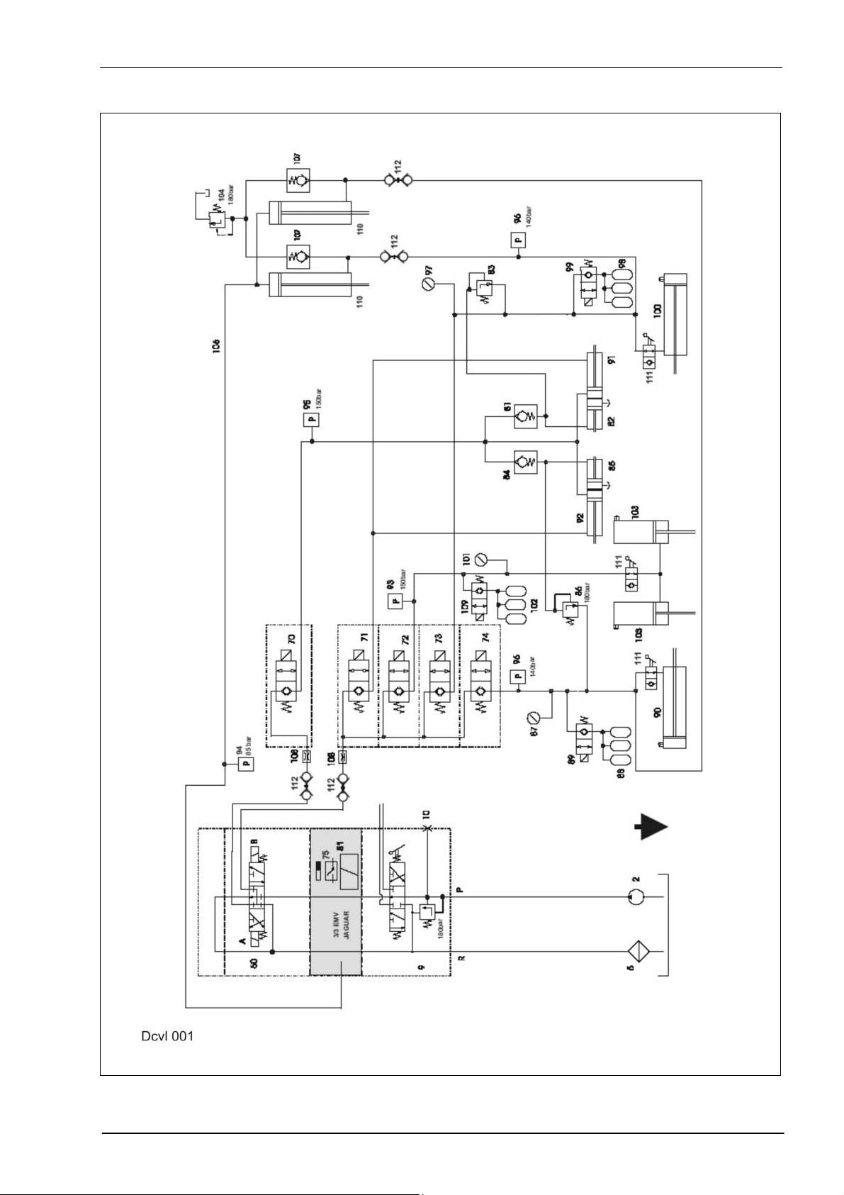
1.0 Hydraulic System
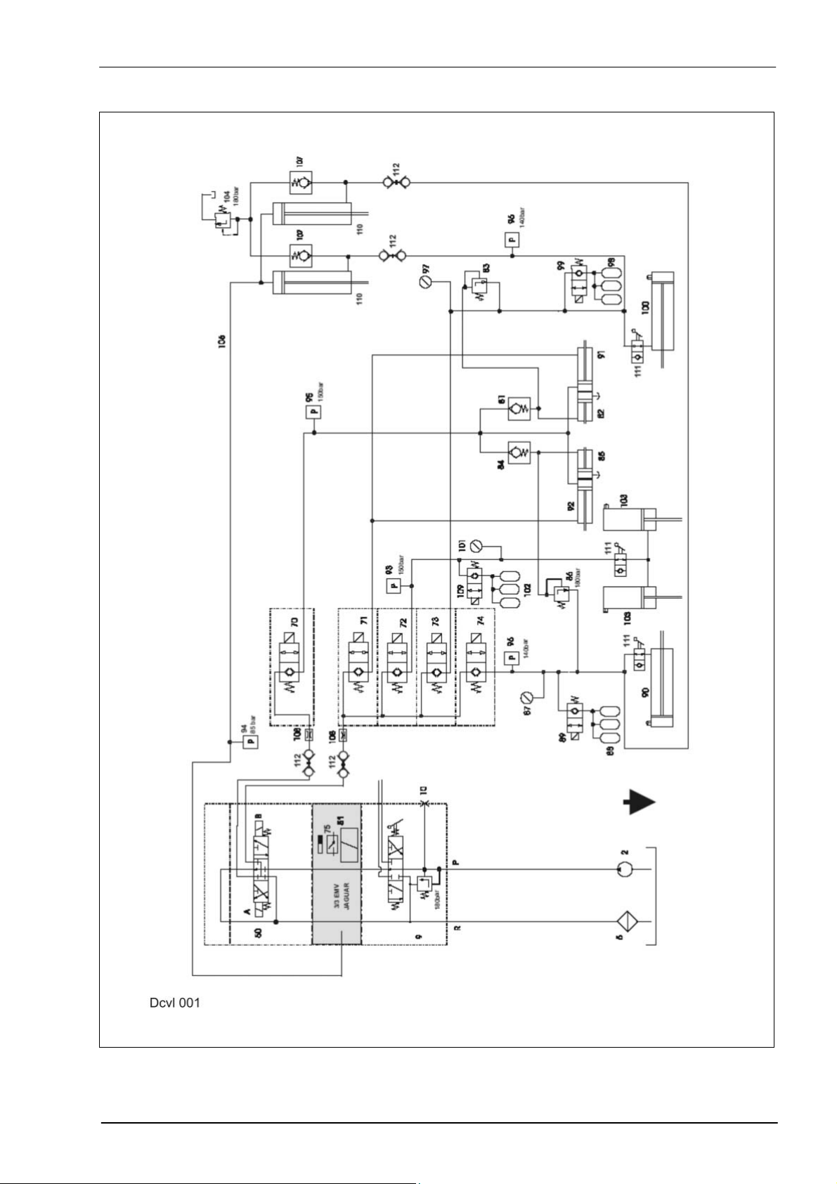
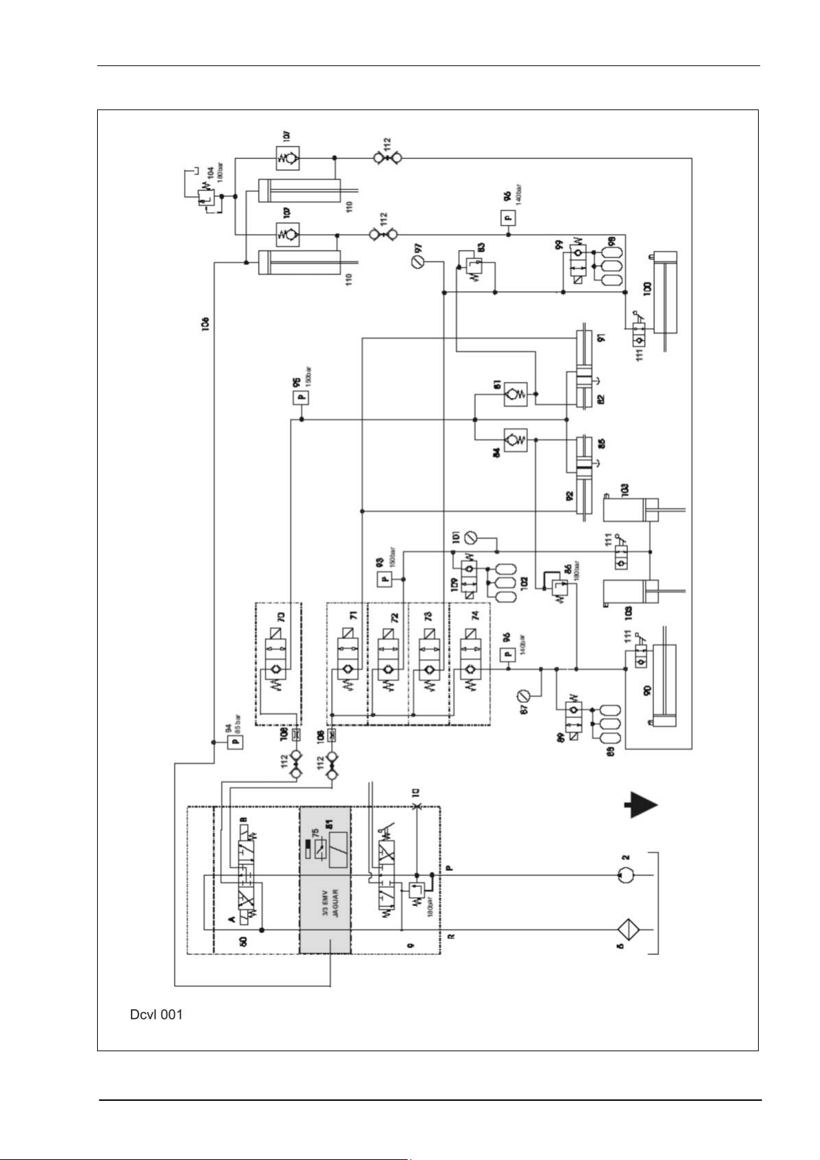
1.1 JAGUAR 8500C-6, C-8 hydraulic circuit diagram
2 Lift hydraulics pump, 12 cm³/rev.
5 Oil filter, lift hydraulics, mesh size 0.06 mm
9 Pressure relief valve with 4/3 way valve, square tube adjustment
10 Pressure gauge connection, lift hydraulics
50 4/3 way solenoid valve, double-acting, for front attachments (series equ.)
51 3/3 way solenoid valve, lift front attachment
70 2/2 way solenoid valve, fold out right and left mower unit
71 2/2 way solenoid valve, fold in right and left Disco
72 2/2 way solenoid valve, raise/lower centre mower unit
73 2/2 way solenoid valve, raise/lower left mower unit
74 2/2 way solenoid valve, raise/lower right mower unit
75 Reed switch (mounted on 3/3 way solenoid valve item 51 = only on
Jaguar 800 series)
81 Non-return valve, left mower unit
82 Hydraulic cylinder, left mower unit, starting protection
83 Pressure relief valve 180 bar
84 Non-return valve, right mower unit
85 Hydraulic cylinder, right mower unit, starting protection
86 Pressure relief valve 180 bar, right mower unit
87 Pressure gauge, right mower unit ground pressure
88 Right mower unit accumulator, charge pressure 35 bar, 0.75 litres
89 Right mower unit lock-up valve unit
(2/2 way solenoid valve, closed when deenergized)
90 Right mower unit raise/lower hydraulic cylinder
91 Left mower unit fold in/out hydraulic cylinder
92 Right mower unit fold in/out hydraulic cylinder
93 Oil pressure switch 150 bar (normally open contact)
94 Oil pressure switch 85 bar (normally open contact)
95 Oil pressure switch 150 bar (normally open contact)
96 2 oil pressure switches 140 bar (normally closed contact)
97 Pressure gauge, left mower unit ground pressure
98 Left mower unit accumulator, charge pressure 35 bar, 0.75 litres
99 Left mower unit lock-up valve unit
(2/2 way solenoid valve, closed when deenergized)
100 Hydraulic cylinder, left mower unit
101 Pressure gauge, centre mower unit ground pressure
102 Centre mower unit accumulator, charge pressure 35 bar, 0.75 litres
103 Centre mower unit raise/lower hydraulic cylinder
104 Pressure relief valve 180 bar
(Jaguar 800 series on the left of the front attachments cylinder,
Jaguar 600 series on the right of the front attachments cylinder)
106 Line to the front attachment cylinders
107 Non-return valve
108 Orifice plate Ø 1.2 mm
109 Centre (front) mower unit lock-up valve unit
(2/2 way solenoid valve, closed when deenergized)
110 Double acting front attachment cylinder, for 8500C, 8500C-6, -8
111 Shut-off tap
112 Screwed coupling
1-2 10/04
Page 7
TIC JAGUAR 8550C Hydraulic / Electric System
JAGUAR 8500 C-6 / C-8 hydraulic circuit diagram
10/04 1-3
Page 8
Hydraulic / Electric System JAGUAR 8550C TIC
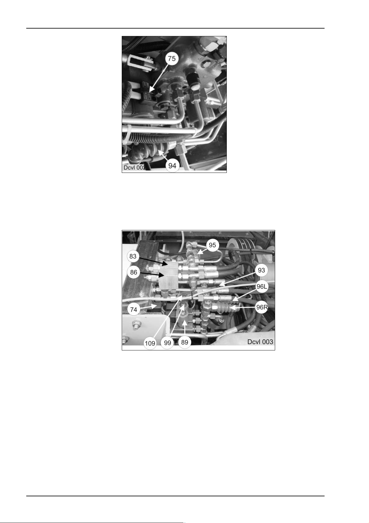
Directional control valves
subassembly
Jaguar 800 series, left side
75 Reed switch
94 Oil pressure switch 85 bar
Attention
The lettering on the Reed switch (75) must face the lift magnet of the 3/3
way solenoid valve = safe switching (the Reed switch in the picture is not
properly mounted).
Directional control valves,
oil pressure switches and
pressure relief valves
(under the cover)
74 2/2 way solenoid valve, raise/lower right mower unit
Next to this: the other Bucher directional control valves 73, 72, 71 and 70.
83 Pressure relief valve 180 bar (left mower unit)
86 Pressure relief valve 180 bar (left mower unit)
89 Right mower unit lock-up valve unit
(2/2 way solenoid valve, closed when deenergized)
93 Oil pressure switch 150 bar (normally open contact), front mower unit
96L Oil pressure switch 140 bar (normally closed contact), left mower unit
96R Oil pressure switch 140 bar (normally closed contact), right mower unit
95 Oil pressure switch 150 bar (normally open contact), fold out mower units
99 Left mower unit lock-up valve unit
(2/2 way solenoid valve, closed when deenergized)
109 Front mower unit lock-up valve unit
(2/2 way solenoid valve, closed when deenergized)
1-4 10/04
Page 9
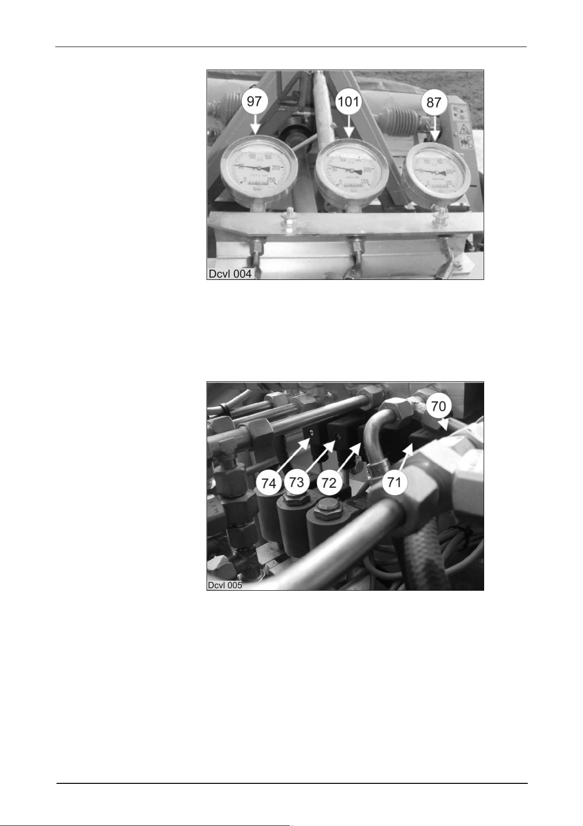
TIC JAGUAR 8550C Hydraulic / Electric System
Pressure gauge for
ground pressure
Bucher 2/2 way valves
(under the cover)
87 Pressure gauge, right mower unit ground pressure
97 Pressure gauge, left mower unit ground pressure
101 Pressure gauge, centre mower unit ground pressure
All pressure gauges show a ground pressure of 50 bar with the mower
units lowered (working position).
70 2/2 way solenoid valve, fold out right and left mower unit
71 2/2 way solenoid valve, fold in right and left mower unit
72 2/2 way solenoid valve, raise/lower centre mower unit
73 2/2 way solenoid valve, Disco left load relief
74 2/2 way solenoid valve, Disco right load relief
10/04 1-5
Page 10
Hydraulic / Electric System JAGUAR 8550C TIC
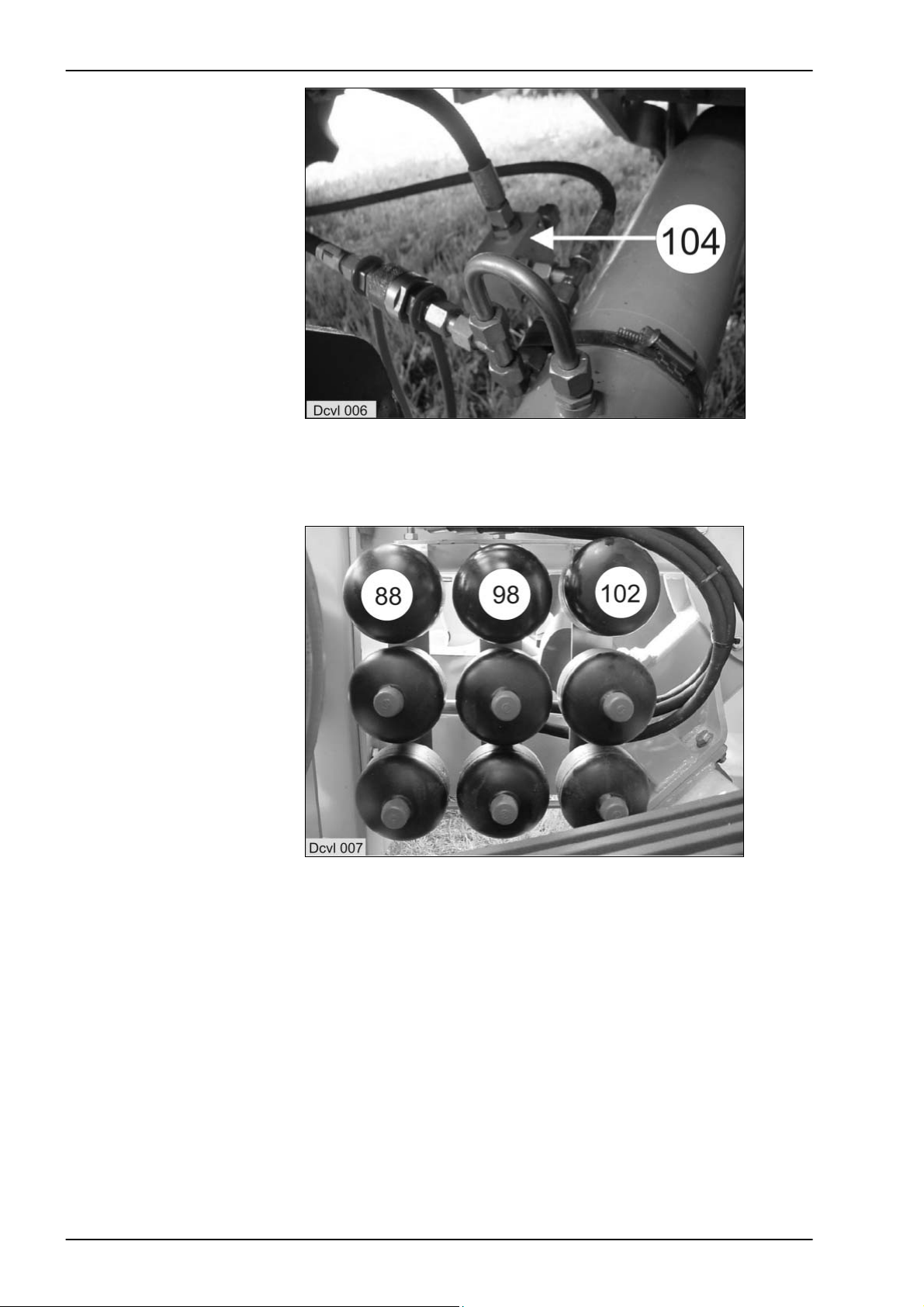
Jaguar front attachment
cylinder pressure relief
valve
Accumulator
behind the right-hand cover
104 Pressure relief valve 180 bar
Jaguar 800 series on the left of the front attachments cylinder,
Jaguar 600 series on the right of the front attachments cylinder
1-6 10/04
88 3 x right mower unit accumulator, charge pressure 35 bar, 0.75 litres
98 3 x left mower unit accumulator, charge pressure 35 bar, 0.75 litres
102 3 x centre mower unit accumulator, charge pressure 35 bar, 0.75 litres
Page 11

TIC JAGUAR 8550C Hydraulic / Electric System
10/04 1-7
Page 12
Hydraulic / Electric System JAGUAR 8550C TIC
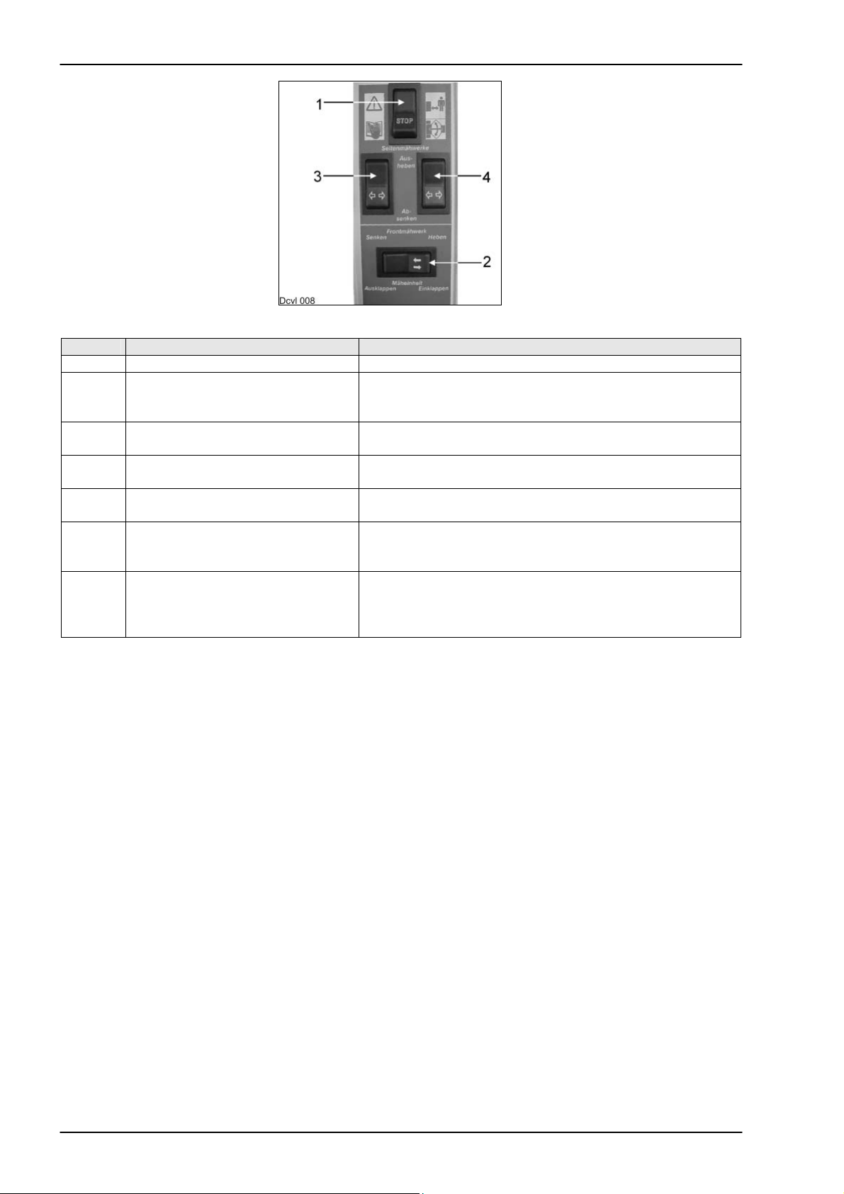
1.2 Function
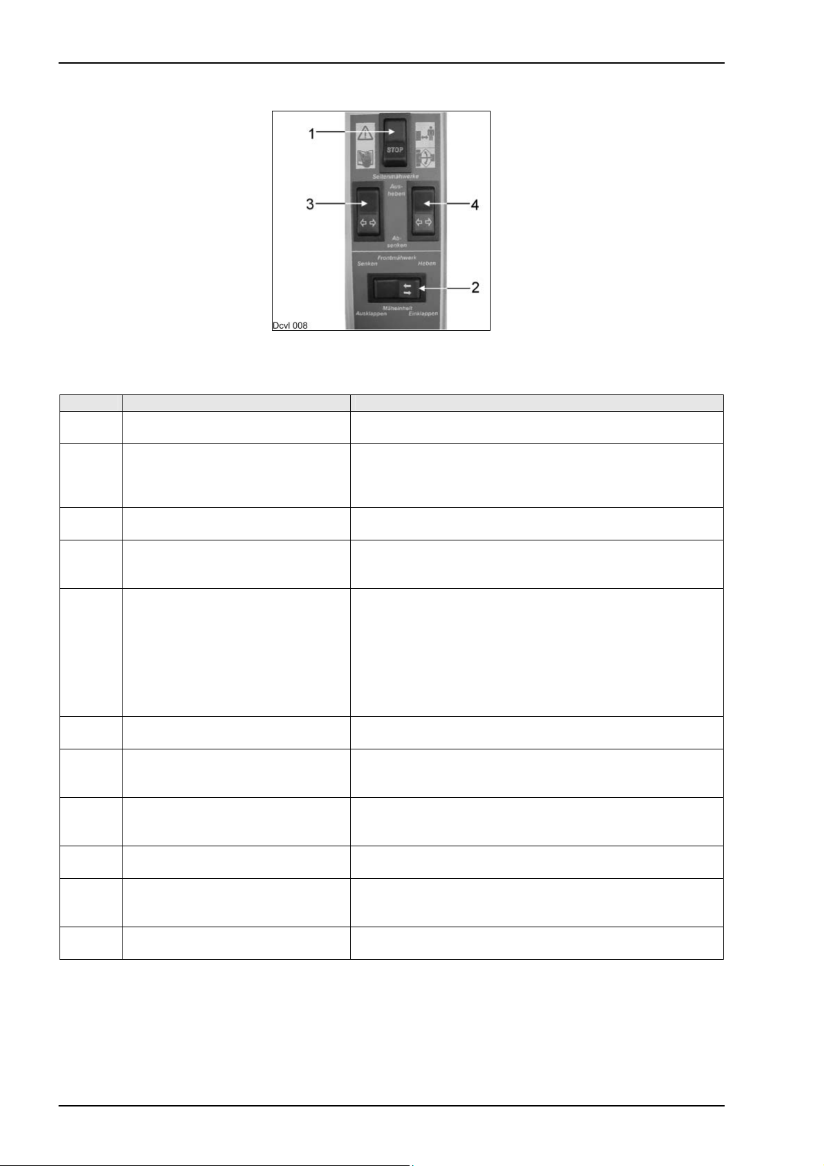
1.2.1 Actuate from
transport to working
position
Caution:
1 = Main switch ON-OFF. Set to OFF when parking the machine.
Step Action Reaction
1 Switch 2 on the CCT is actuated to
the right
Solenoid valve 50 goes to position B.
Volume flow goes to the solenoid valves 71, 72, 73 and 74.
2 Solenoid valve 72 is triggered The applied volume flow goes to cylinder 103.
The front mower unit is raised to its end position = the
pressure rises and oil pressure switch 93 switches at
3 Solenoid valves 70 and 71 are
triggered.
4 The displaced volume flow from the
ram top space flows to the tank via
the energized solenoid valve 70.
5 Switch 2 on the CCT is actuated to
the left
150 bar.
Volume flow goes to the rod spaces of cylinder 91 and 92
via the solenoid valve 71.
The side-mounted mower unit are folded in.
The lock can be released.
Solenoid valve 50 goes to position A.
Solenoid valves 70 and 71 are triggered. This makes
volume flow flow through solenoid valves 70:
into cylinders 82 and 85 (but also the non-return valves 81
and 84).
into cylinders 91 and 92. The side-mounted mower units
are now folded out and the starting protections are
6 Cylinders travel against their end
stop
activated.
Pressure switch 95 switches at a pressure of 150 bar.
7 Solenoid valve 72 is triggered Volume flow from cylinders 103 flows through 72 and
solenoid valve 50 (position A) into the tank. The front
8 The lower command for the left
mower unit is issued on the control
terminal (switch 3).
9 Volume flow from cylinder 100
mower unit is lowered.
Solenoid valve 50 goes to position A.
Solenoid valve 73 is energized.
The left mower unit is lowered.
flows into the tank.
10 The lower command for the right
mower unit is issued on the control
terminal (switch 4).
11 Volume flow from cylinder 90 flows
into the tank.
Solenoid valve 50 goes to position A.
Solenoid valve 74 is energized.
The right mower unit is lowered.
During work, the working pressures of all cylinders are supported by the accumulators 88, 98 and 102. The
lock-up valve units are opened at switch 94 below 80 bar. When the pressure rises to above 85 bar, the
lock-up valve units are closed and the mower units remain in their position. The ground pressure of the
mower units can be seen on pressure gauges 87, 97 and 101.
1-8 10/04
Page 13

TIC JAGUAR 8550C Hydraulic / Electric System
JAGUAR 8500 C-6 / C8 hydraulic circuit diagram
10/04 1-9
Page 14
Hydraulic / Electric System JAGUAR 8550C TIC
1.2.2 Raising the entire
mower unit
Step Action Reaction
1 The “Raise front attachment”
button on the forage harvester is
pressed.
Via the 3/3 way solenoid valve of the jaguar (line 106),
volume flow goes to the ram rod end of lifting cylinders
(110).
2 The mower unit is raised. When a pressure of 85 bar is reached while raising, the
pressure switch 94 (normally open contact) switches.
3 The relays 12 and 15 now cut the
power supply to the lock-up valve
units 89, 99 and 109.
4 The volume flow displaced from the
rod spaces of the cylinders (on the
The lock-up valve units are closed. This is required to keep
all mower units raised while raising the overall mower unit.
(The oil does not flow into the accumulators 88, 98 and
102.)
The cylinders 90 and 100 retract and thus raise the left and
right mower units.
forage harvester) is fed to the
cylinders 90 and 100.
5 When the volume capacity of the
rod spaces of cylinders 90 and 100
is exhausted,
the pressure rises and the pressure switches 96 switch the
lock-up valve units 89 and 99 so that the excess volume
flow is displaced into the accumulators 88 and 98. This
ensures that no oil will escape from this circuit.
1.2.3 Starting protection
Step Action Reaction
1 If e.g. the right mower unit hits an
obstacle.
2 When the pressure reaches
180 bar,
3 Volume flow is displaced from the
rod space of cylinder 85.
The pressure in rod space of cylinder 85 rises.
the pressure relief valve 86 opens.
This volume flow goes to the rod space of cylinder 90. The
right mower unit is raised and folds in.
1-10 10/04
Page 15
TIC JAGUAR 8550C Hydraulic / Electric System
JAGUAR 8500 C-6 / C8 hydraulic circuit diagram
10/04 1-11
Page 16
Hydraulic / Electric System JAGUAR 8550C TIC
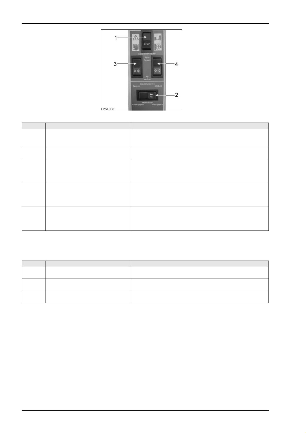
1.2.4 Actuating from
working to
transport position
Step Action Reaction
1 Shut down the mower unit. The mower discs must not rotate any more.
2 Push the “Raise” key in the ground
until the mower units have no more ground contact.
speed control lever (3/3 way
solenoid valve is energized)
3 Push switch 2. Solenoid valve 72 is energized.
Solenoid valve 50 goes to switch position B.
4 Volume flow goes to hydraulic
The cylinders 103 raise the centre mower unit.
cylinders 103.
5 Cylinders 103 travel to their end
The pressure rises.
stop.
6 When the pressure reaches
Solenoid valves 70 and 71 are energized.
150 bar, the oil pressure switch 93
switches
7 Volume flow flows through the
energized solenoid valve 71 into
the rod spaces of cylinders 91 and
92.
The volume flow displaced from the ram top spaces flows
into the tank through the energized solenoid valve 70 and
on via the 4/3 way solenoid valve 50B.
The side-mounted mower units are folded in.
1-12 10/04
Page 17
TIC JAGUAR 8550C Hydraulic / Electric System
JAGUAR 8500 C-6 / C8 hydraulic circuit diagram
10/04 1-13
Page 18

Hydraulic / Electric System JAGUAR 8550C TIC
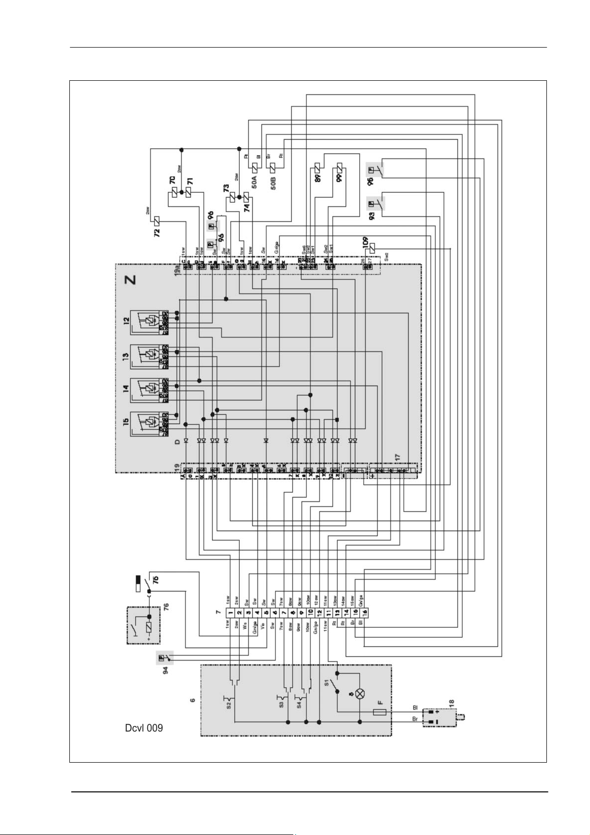
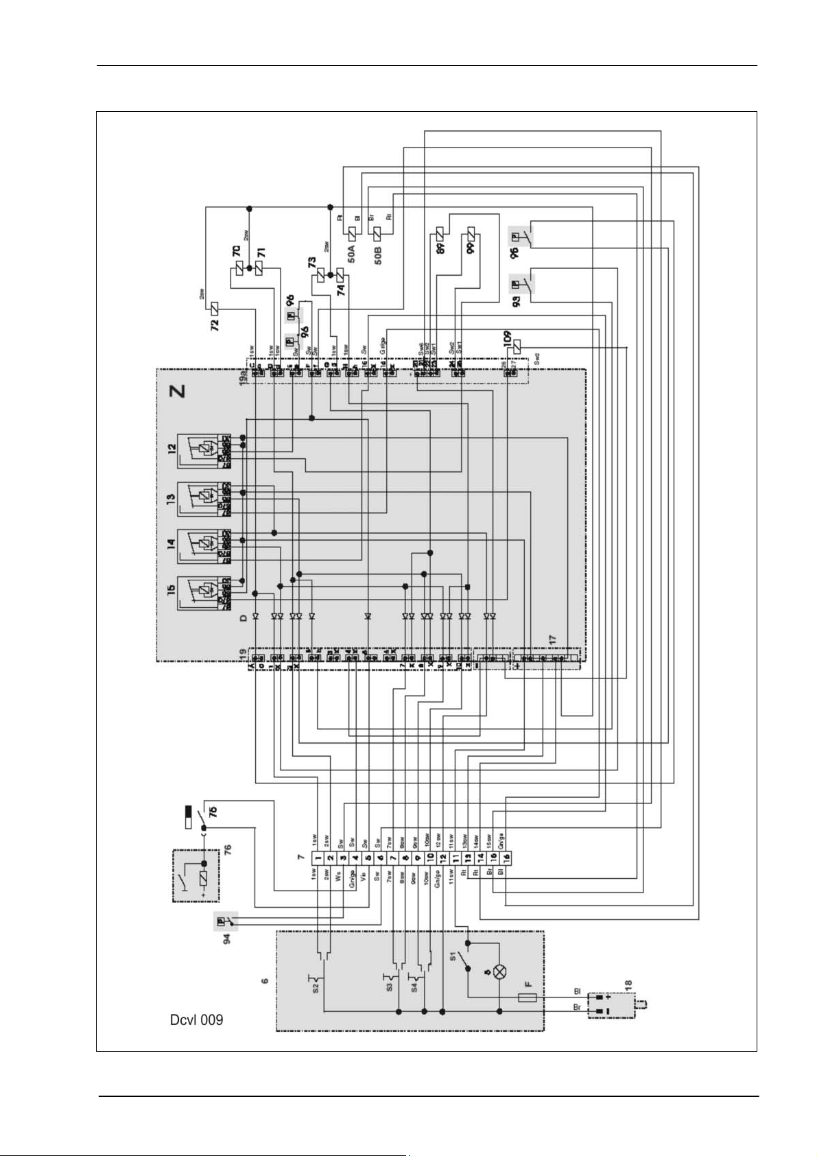
2.0 Electric system JAGUAR 8500C, CISCO 8500C-6, -8
2.1 Electric circuit diagram
S1 Stop switch
S2 Disco fold in/out switch
S3 Left Disco raise/lower switch
S4 Right Disco raise/lower switch
5 Indicator light, power supply
6 Control box with switches S1, S2, S3 and S4
7 Socket outlet beneath the operator's platform
17 Terminal strip, plus in central terminal compartment
(located above the relays)
19 Left terminal strip
19a Right terminal strip
12 Lock-up valve unit 89 and 99 relay
13 Relay for 4/3 way solenoid valve (item 50A)
14 Relay for 4/3 way solenoid valve (item 50B)
15 Relay for lock-up valve unit 109
50 4/3 way solenoid valve for front attachment (series equipment)
50A Solenoid coil (fold out mower units)
50B Solenoid coil (fold in mower unit, raise/lower)
51 Front attachment raise/lower 3/3 way solenoid valve
70 Solenoid coil, fold out right and left Disco
71 Solenoid coil, fold in right and left Disco
72 Solenoid coil, raise/lower centre Disco
73 Left Disco raise/lower solenoid coil
74 Right Disco raise/lower solenoid coil
75 Reed switch (only Jaguar 800 series)
Mounted to solenoid valve 51 (raise).
Caution: Observe installation position = lettering must face the magnet
76
Switches and 3/3 way raise solenoid valve
(only on Jaguar 600 series)
89 Solenoid coil, right lock-up valve unit (closed when deenergized)
93 Oil pressure switch 150 bar (normally open contact), energizes solenoid
valve 70
94 Oil pressure switch 85 bar (normally open contact), energizes relay 12
95 Oil pressure switch 150 bar (normally open contact), energizes solenoid
valve 72
96 2x oil pressure switch 140 bar (normally closed contact), see chapter
2.2.8.
99 Solenoid coil, left lock-up valve unit (closed when deenergized)
109 Solenoid coil, centre lock-up valve unit (closed when deenergized)
D Diodes
F 10 A fuse
Z Central terminal compartment (the lines in the areas with a grey
background are actually conducting paths on the board).
1-14 10/04
Page 19

TIC JAGUAR 8550C Hydraulic / Electric System
Electric system Jaguar 8500C, Disco 8500C-6, C-8
10/04 1-15
Page 20

Hydraulic / Electric System JAGUAR 8550C TIC
2.2 Function
2.2.1 Putting into operation Switch on stop switch 1.
2.2.2 Raise left Disco Actuate rocker switch 3. Earth is connected to pin 7 in connector 7.
2.2.3 Lower left Disco Actuate rocker switch 3. Earth is connected to pin 7 in connector 8.
2.2.4 Raise right Disco Actuate rocker switch 4.
2.2.5 Lower right Disco Actuate rocker switch 4.
2.2.6 Moving the Disco to
working position
2.2.7 Moving the Disco to
transport position
Current is applied to all relays, terminal 86 and the solenoid valves.
Earth is also connected to relay 14 on terminal 85 and to solenoid valve
73. Relay 14 connects earth to the 4/3 way directional control valve 50B.
Earth is also connected to relay 13 on terminal 85 and to solenoid valve
73. Relay 13 connects earth to the 4/3 way directional control valve 50A.
Earth is connected via pin 9 of connector 7 to relay 14 on terminal 85 and
to the solenoid valve 74. Relay 14 connects earth to the solenoid valve
50 which goes to switch position B.
Earth is connected via pin 10 of connector 7 to relay 13 on terminal 85
and to the solenoid valve 74. Relay 13 connects earth to the solenoid
valve 50 which goes to switch position A.
Actuate rocker switch 2.
Earth is connected via pin 2 of connector 7 to relay 13 on terminal 85 and
to the solenoid valves 70 and 71. Relay 13 connects earth to the solenoid
valve 50 which goes to switch position A.
The mower unit folds out.
Upon reaching the end position and 150 bar, the oil pressure switch 95
connects earth to the solenoid valve 72. The front mower unit is lowered
via the energized solenoid valve 72.
Actuate rocker switch 2.
Earth is connected via pin 1 of connector 7 to relay 14 on terminal 85 and
to the solenoid valve 72.
Relay 14 connects earth to the solenoid valve 50 which goes to switch
position B.
The centre mower unit is raised.
Upon reaching the end position and 150 bar, the oil pressure switch 93
connects earth to the solenoid valves 70 and 71. The mower units are
folded in.
1-16 10/04
Page 21
TIC JAGUAR 8550C Hydraulic / Electric System
Electric system Jaguar 8500C, Disco 8500C-6, C-8
10/04 1-17
Page 22

Hydraulic / Electric System JAGUAR 8550C TIC
2.2.8 Blocking the
accumulator while
raising the entire
mower unit.
(quick lift)
When the 3/3 way raise front attachment solenoid valve is actuated on
the forage harvester, the Reed switch*75 connects earth to relay 15,
terminal 85 and relay 12, terminal 85.
Relay 15 cuts the current to the lock-up valve unit 109.
Relay also cuts the current to the lock-up valve units 89 and 99 (the lockup valve units are closed when deenergized).
When raising is complete, the mower units’ weight generates a pressure
of > 85 bar in the cylinders of the Jaguar front attachment.
The oil pressure switch 94 connects earth to relay 12, terminal 85 as long
as the pressure in the lift cylinders is > 80 bar.
Relay 12 switches and cuts the power supply to the lock-up valve units
89, 99 and 109.
This is necessary to make the mower units remain in their position when
lifting is complete on the turning area. When the pressure in cylinders 90
and 100 rises to above 140 bar, the oil pressure switches 96 open briefly.
Earth connected to relay 12, terminal 85 drops out and the relay connects
the current supply to the lock-up valve units 89 and 99.
The lock-up valve units open and the accumulators receive oil from the
ram rod end (from the front attachment cylinders on the Jaguar) so that
there is no oil loss and no oil can flow from the system into the tank
(pressure relief valve 104).
* On the Jaguar 800, the Reed switch connects earth.
On the Jaguar 600, earth is supplied directly from the 3/3 way „Raise“
solenoid valve.
1-18 10/04
Page 23
TIC JAGUAR 8550C Hydraulic / Electric System
Electric system Jaguar 8500C, Disco 8500C-6, C-8
10/04 1-19
Page 24
Hydraulic / Electric System JAGUAR 8550C TIC
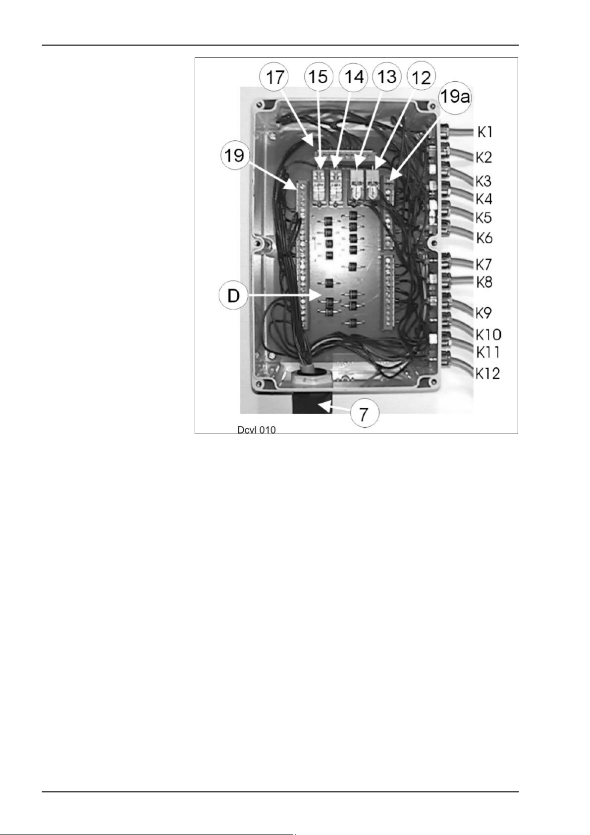
2.3 Central terminal compartment
7 Central terminal compartment connector
12 Lock-up valve unit 89 and 99 relay
13 Relay for 4/3 way solenoid valve (item 50A)
14 Relay for 4/3 way solenoid valve (item 50B)
15 Relay for lock-up valve unit 109
17 Terminal strip, plus in central terminal compartment
(located above the relays)
19 Left terminal strip
19a Right terminal strip
K1 Raise/lower right side-mounted mower unit, solenoid valve 74
K2 Raise/lower left side-mounted mower unit, solenoid valve 73
K3 Front mower unit, solenoid valve 72
K4 Right mower unit lock-up valve unit, solenoid valve 89
K5 Left mower unit lock-up valve unit, solenoid valve 99
K6 Front mower unit lock-up valve unit, solenoid valve 109
K7 Fold out side-mounted mower unit, solenoid valve 70
K8 Fold in side-mounted mower unit, solenoid valve 71
K9 140 bar pressure switch, item 96
K10 140 bar pressure switch, item 96
K11 150 bar pressure switch (fold in side-mounted mower units), item 93
K12 150 bar pressure switch (fold out side-mounted mower units), item 95
D Diodes
1-20 10/04
Page 25
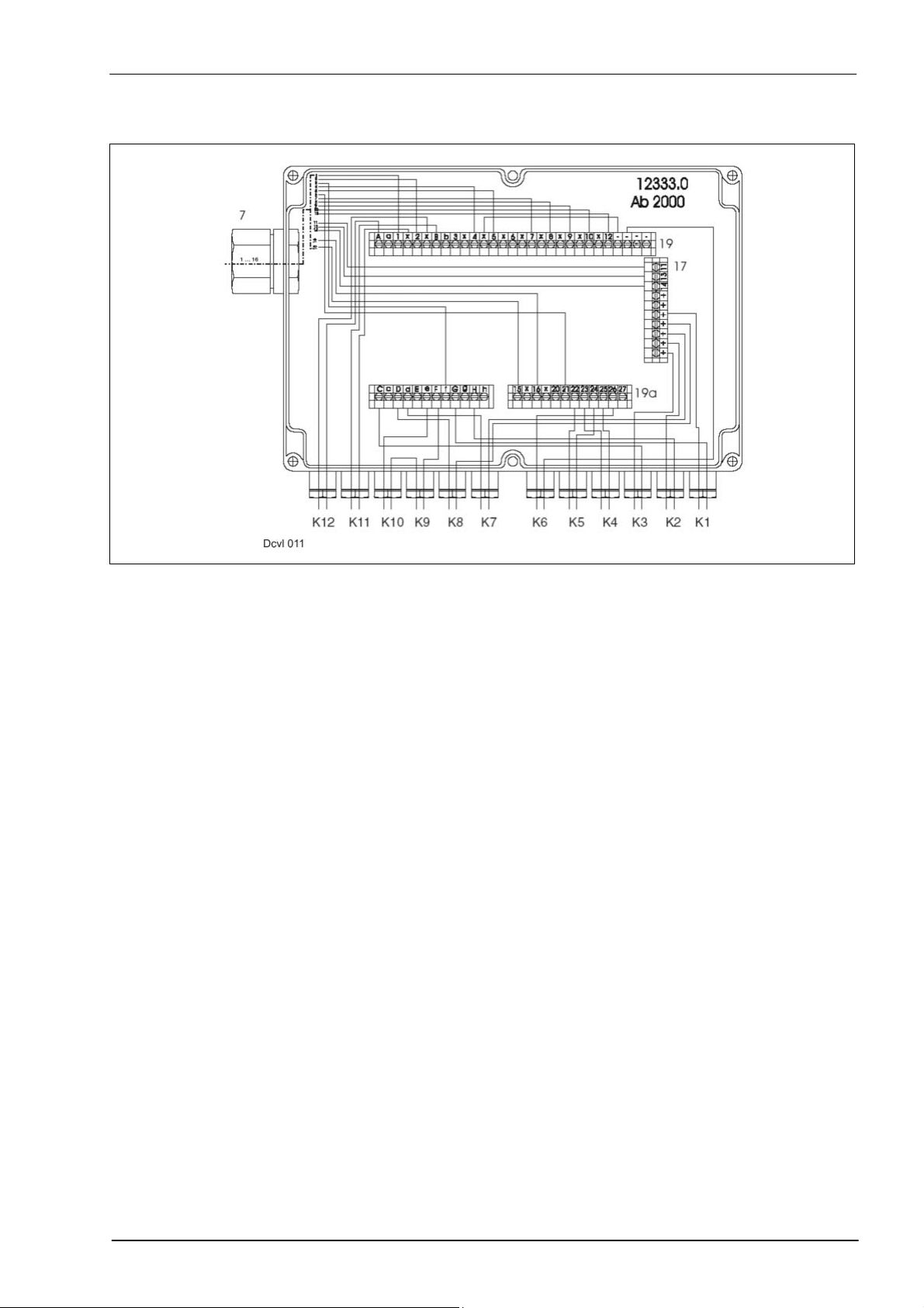
TIC JAGUAR 8550C Hydraulic / Electric System
Central terminal
compartment, from 2000
7 Central terminal compartment connector
12 Lock-up valve unit 89 and 99 relay
13 Relay for 4/3 way solenoid valve (item 50A)
14 Relay for 4/3 way solenoid valve (item 50B)
15 Relay for lock-up valve unit 109
17 Terminal strip, plus in central terminal compartment
(located above the relays)
19 Left terminal strip
19a Right terminal strip
K1 Raise/lower right side-mounted mower unit, solenoid valve 74
K2 Raise/lower left side-mounted mower unit, solenoid valve 73
K3 Front mower unit, solenoid valve 72
K4 Right mower unit lock-up valve unit, solenoid valve 89
K5 Left mower unit lock-up valve unit, solenoid valve 99
K6 Front mower unit lock-up valve unit, solenoid valve 109
K7 Fold out side-mounted mower unit, solenoid valve 70
K8 Fold in side-mounted mower unit, solenoid valve 71
K9 140 bar pressure switch, item 96
K10 140 bar pressure switch, item 96
K11 150 bar pressure switch (fold in side-mounted mower units), item 93
K12 150 bar pressure switch (fold out side-mounted mower units), item 95
10/04 1-21
Page 26
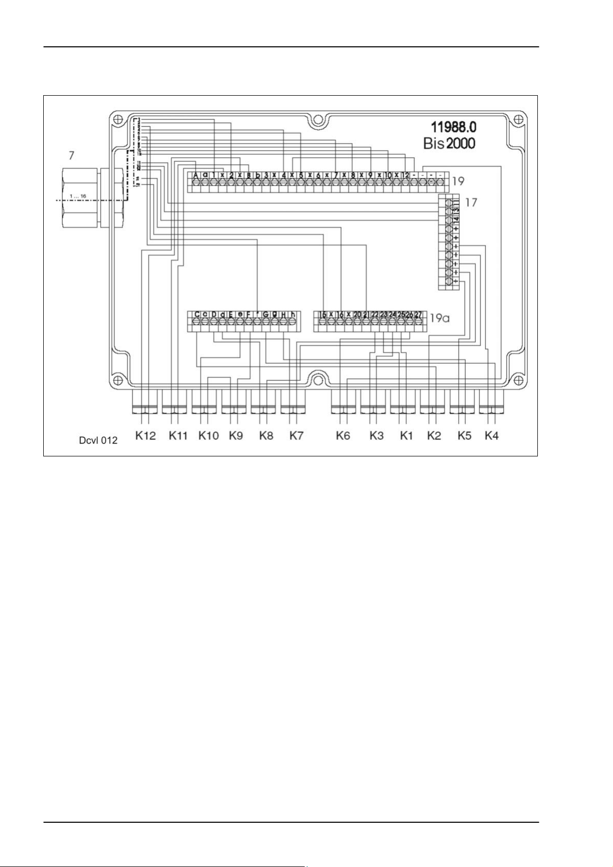
Hydraulic / Electric System JAGUAR 8550C TIC
Central terminal
compartment, up to 2000
Differences as compared with central terminal compartment
“from 2000”:
The assignment of inputs 1 to K5 is different.
The connecting terminals on the board have not been changed.
7 Central terminal compartment connector
12 Lock-up valve unit 89 and 99 relay
13 Relay for 4/3 way solenoid valve (item 50A)
14 Relay for 4/3 way solenoid valve (item 50B)
15 Relay for lock-up valve unit 109
17 Terminal strip, plus in central terminal compartment (located above the
relays)
19 Left terminal strip
19a Right terminal strip
K1 Raise/lower right side-mounted mower unit, solenoid valve 74
K2 Raise/lower left side-mounted mower unit, solenoid valve 73
K3 Front mower unit, solenoid valve 72
K4 Right mower unit lock-up valve unit, solenoid valve 89
K5 Left mower unit lock-up valve unit, solenoid valve 99
K6 Front mower unit lock-up valve unit, solenoid valve 109
K7 Fold out side-mounted mower unit, solenoid valve 70
K8 Fold in side-mounted mower unit, solenoid valve 71
K9 140 bar pressure switch, item 96
K10 140 bar pressure switch, item 96
K11 150 bar pressure switch (fold in side-mounted mower units), item 93
K12 150 bar pressure switch (fold out side-mounted mower units), item 95
1-22 10/04
Page 27
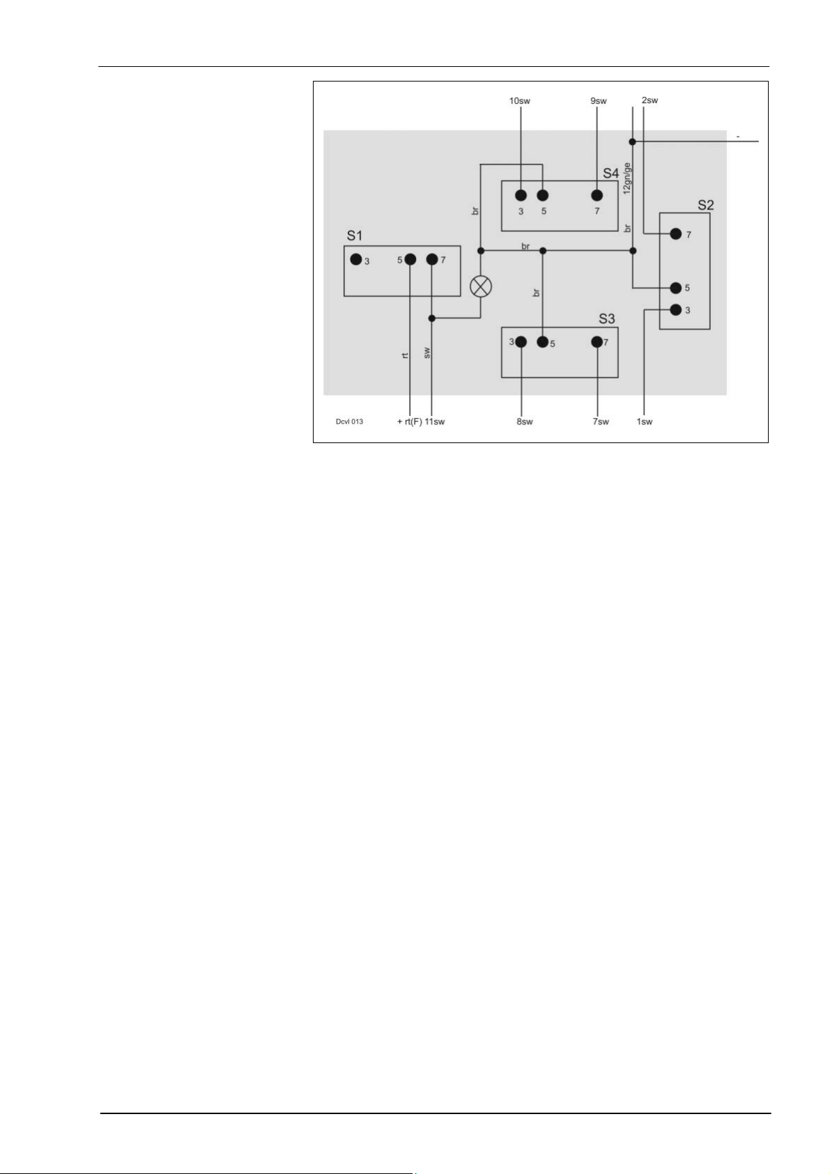
TIC JAGUAR 8550C Hydraulic / Electric System
Pin assignment of switches
in the CCT
(as seen from the rear)
S1 Stop switch
S2 Disco fold in/out switch
S3 Left Disco raise/lower switch
S4 Right Disco raise/lower switch
10/04 1-23
Page 28
Hydraulic / Electric System JAGUAR 8550C TIC
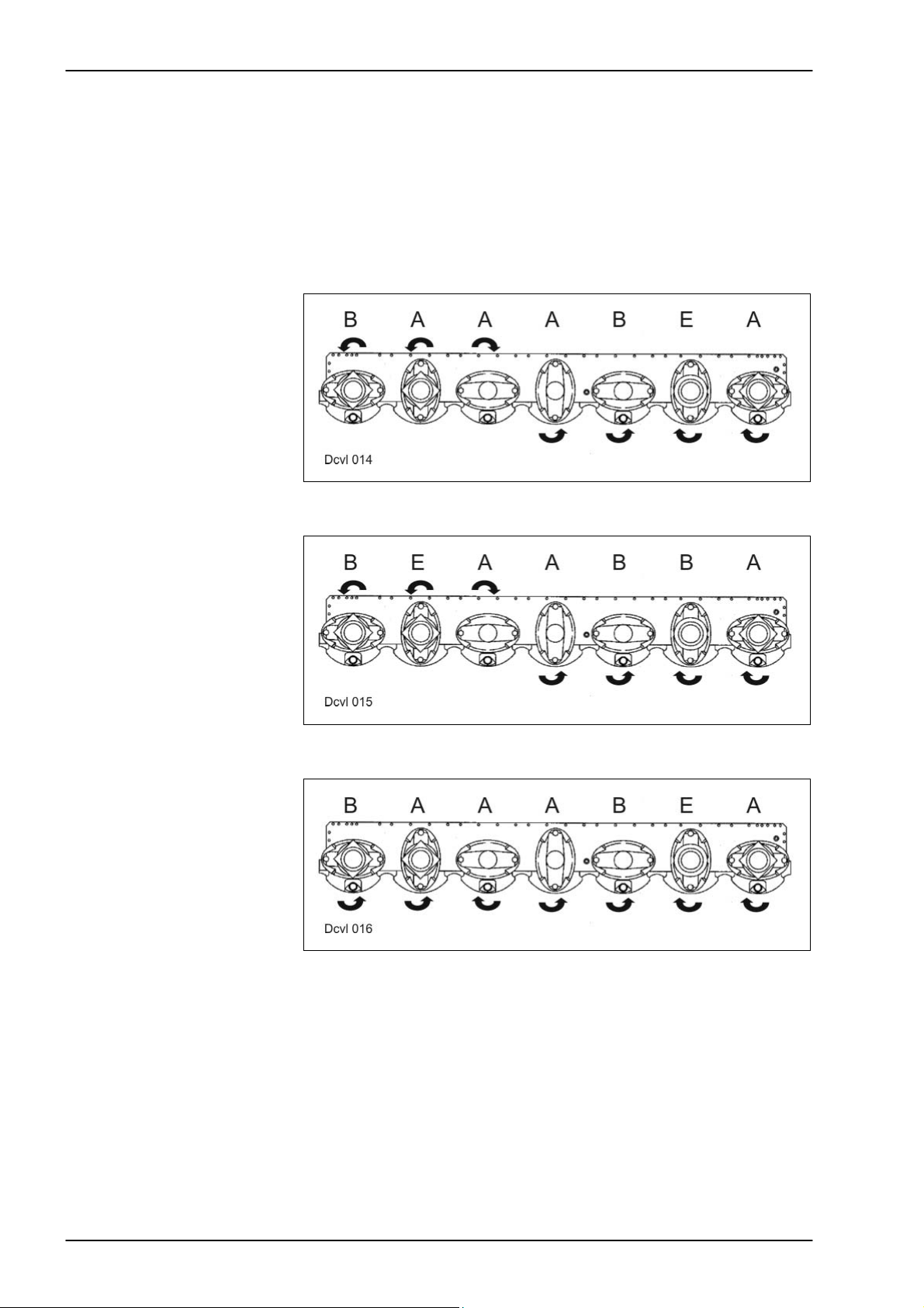
3.0 Installation information
3.1 Timing of drives
Arrangement of pinion units A and B and of drive input module E
Left mower unit
A Pinion unit A
B Pinion unit B
E Drive input module
Right mower unit
A Pinion unit A
B Pinion unit B
E Drive input module
In addition to the drive input module E, 6 rows of pinions are provided in
the mower head.
These are sub-divided into four 4 versions and two B versions. The B
versions are marked with red paint at the bottom.
Centre mower unit
A Pinion unit A
B Pinion unit B
E Drive input module
1-24 10/04
Page 29
TIC JAGUAR 8550C Hydraulic / Electric System
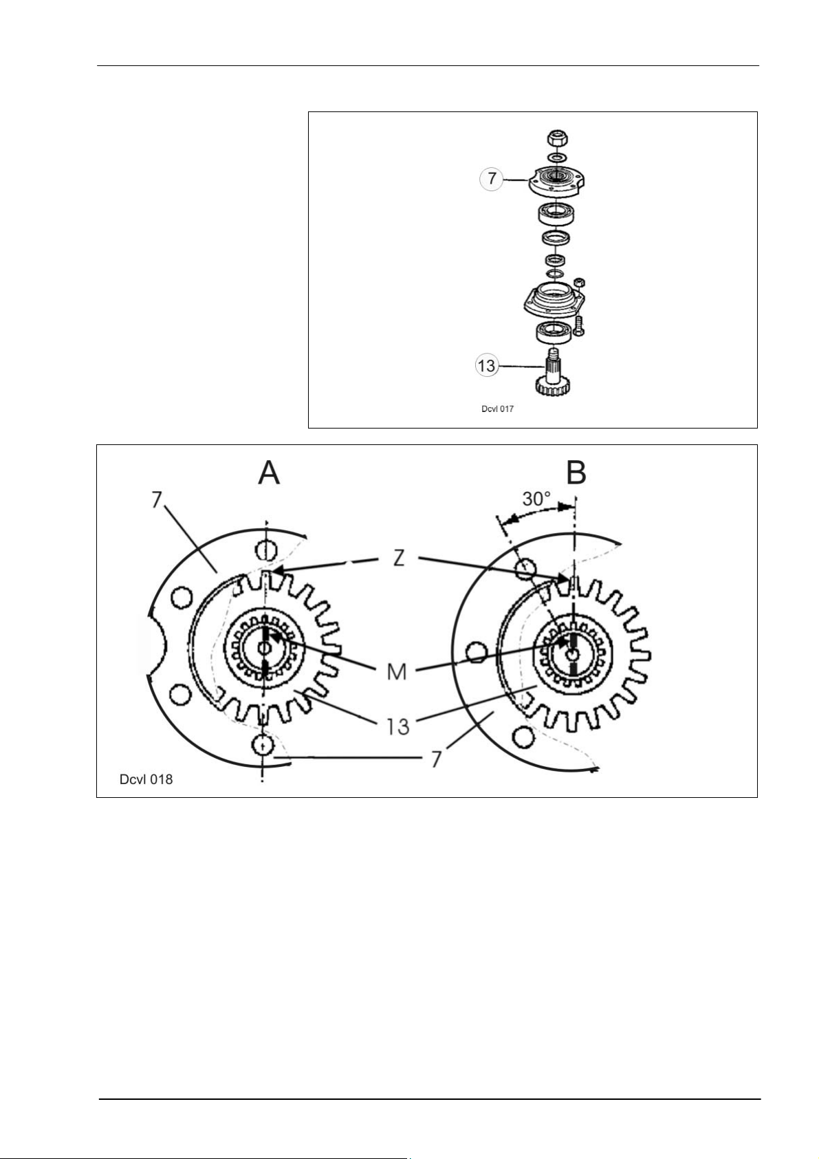
3.2 Installation of pinion units
7 Flange
13 Pinion shaft
Pinion unit A The marking M on the pinion shaft (13), the tooth centre Z and the centre
of the flange bore must be aligned.
Pinion unit B The marking M on the shaft, the tooth centre Z and the centre between
two flange bores must be aligned.
10/04 1-25
Page 30
Hydraulic / Electric System JAGUAR 8550C TIC
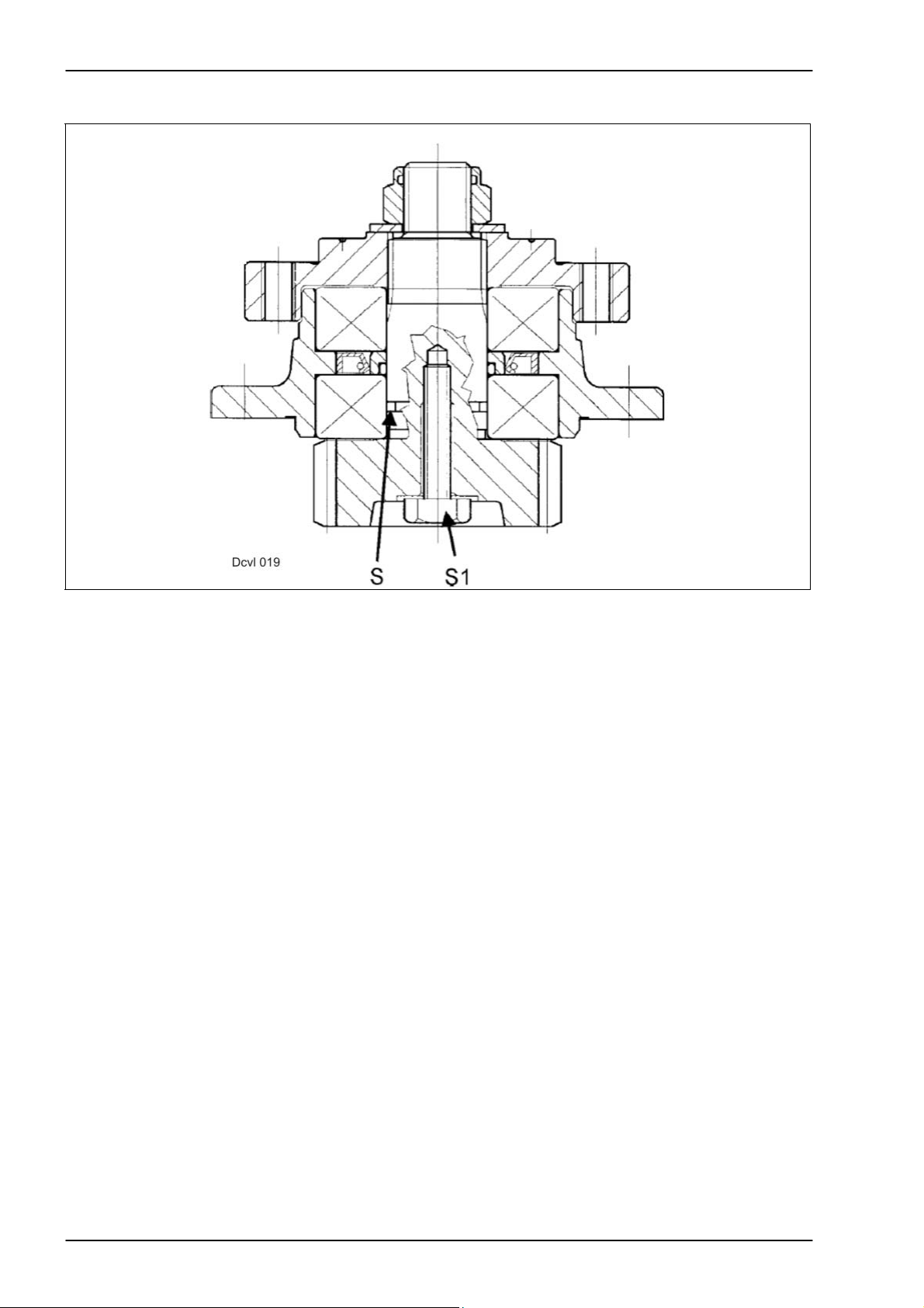
3.3 Safety module
S Breaking point for cases of sudden load
S1 Safety screw (when sudden loads occur and the pinion has been sheared
off the shaft, this screw holds both parts together and thus avoids major
damage in the mower head).
1-26 10/04
Page 31

TIC JAGUAR 8550C Hydraulic / Electric System
3.4 Tightening torques
Item Remark Tightening torque
1 M 10x30 bolt 85 Nm
2 M 10x20 countersunk head bolt 70 Nm
3 M 10x19 bolt 85 Nm
4 M 10x55x45 countersunk head bolt 70 Nm
5 M 20x30 cheese-head screw 650 Nm
6 M 10x40 bolt 85 Nm
10/04 1-27
Page 32

Hydraulic / Electric System JAGUAR 8550C TIC
4.0 Drive diagram
1-28 10/04
Page 33

TIC DISCO 8550C (Tractor) Hydraulic / Electric System
Hydraulic System...................................................................................................................................2
1.0
1.1
Hydraulic circuit diagram......................................................................................................................2
2.0
Electric System ......................................................................................................................................4
2.1
Electric circuit diagram .........................................................................................................................4
3.0 Installation information.........................................................................................................................6
Timing of drives....................................................................................................................................6
3.1
3.2 Installation of pinion units.....................................................................................................................7
3.3 Safety module ......................................................................................................................................8
3.4 Tightening torques ...............................................................................................................................9
4.0 Drive diagram.......................................................................................................................................10
10/04 2-1
Page 34

Hydraulic / Electric System DISCO 8550C (Tractor) TIC
1.0 Hydraulic System
1.1 Hydraulic circuit diagram
1 Coupling, single-acting
2 Cylinder for front mower units
3 Cylinder for front mower units
4 Oil pressure switch, set to 190 bar
5 Flow divider
6 Cylinder with 3/2 way directional control valve – Raise/lower side-
mounted mower units
7 Cylinder with 3/2 way directional control valve – Raise/lower side-
mounted mower units
4 Oil pressure switch, set to 190 bar
5 Flow divider
2-2 10/04
Page 35

TIC DISCO 8550C (Tractor) Hydraulic / Electric System
10/04 2-3
Page 36

Hydraulic / Electric System DISCO 8550C (Tractor) TIC
2.0 Electric System
2.1 Electric circuit diagram
Activating / deactivating the
transport stop
1 Connector – tractor connection
2 Control terminal
3 Cable connections
4 4-pin connector for control terminal – basic machine
5 Oil pressure switch
6 Solenoid valve on cylinder, left
7 Solenoid valve on cylinder, right
Deactivating the transport
stop
Press both “0” keys simultaneously. Both LEDs (L) light up; the two
2/2 way solenoid valves (6 and 7) on the cylinder are energized and are
open.
Activating the transport stop Raise all mower units. This makes the system pressure rise; at 190 bar,
the oil pressure switch (4) activates the transport stop automatically. Both
LEDs have gone out.
or
The transport stop is active whenever one of the two "0" keys is pressed.
Both LEDs have gone out.
2-4 10/04
Page 37

TIC DISCO 8550C (Tractor) Hydraulic / Electric System
DISCO 8500 C (tractor) electric circuit diagram
10/04 2-5
Page 38

Hydraulic / Electric System DISCO 8550C (Tractor) TIC
3.0 Installation information
3.1 Timing of drives
Arrangement of pinion units A and B and of drive input module E
Left mower unit
A Pinion unit A
E Drive input module
Right mower unit
A Pinion unit A
E Drive input module
In addition to the drive input module E, 6 rows of pinions are provided in
the mower head.
These are sub-divided into four 4 versions and two B versions. The B
versions are marked with red paint at the bottom.
Centre mower unit
A Pinion unit A
B Pinion unit B
E Drive input module
2-6 10/04
Page 39

TIC JAGUAR 8550C (Tractor) Hydraulic / Electric System
3.2 Installation of pinion units
7 Flange
13 Pinion shaft
Pinion unit A The marking M on the pinion shaft (13), the tooth centre Z and the centre
of the flange bore must be aligned.
Pinion unit B The marking M on the shaft, the tooth centre Z and the centre between
two flange bores must be aligned.
10/04 2-7
Page 40

Hydraulic / Electric System DISCO 8550C (Tractor) TIC
3.3 Safety module
S Breaking point for cases of sudden load
S1 Safety screw (when sudden loads occur and the pinion has been sheared
off the shaft, this screw holds both parts together and thus avoids major
damage in the mower head).
2-8 10/04
Page 41

TIC JAGUAR 8550C (Tractor) Hydraulic / Electric System
3.4 Tightening torques
Item Remark Tightening torque
1 M 10x30 bolt 85 Nm
2 M 10x20 countersunk head bolt 70 Nm
3 M 10x19 bolt 85 Nm
4 M 10x55x45 countersunk head bolt 70 Nm
5 M 20x30 cheese-head screw 650 Nm
6 M 10x40 bolt 85 Nm
10/04 2-9
Page 42

Hydraulic / Electric System DISCO 8550C (Tractor) TIC
4.0 Drive diagram
2-10 10/04
Page 43

TIC JAGUAR 8550C (Tractor) Hydraulic / Electric System
Figure:
Push-type combination
Front mower unit: Standard Disco 3000FC
Side-mounted mower units: Identical with Disco 300C except for the
frame, the drive and the feed drum.
Figure:
Push-type/pull-type
combination
Front mower unit: Standard Disco 3000FC
Side-mounted mower units: Identical with Disco 300C except for the
frame, the drive and the feed drum.
10/04 2-11
Page 44

Hydraulic / Electric System DISCO 8550C (Tractor) TIC
2-12 10/04
Page 45

TIC CORTO 8100 F/T Hydraulic / Electric System
CORTO 8100F.........................................................................................................................................2
1.0
1.1 CORTO 8100F hydraulic system .........................................................................................................2
1.1.1
Key to diagram..............................................................................................................................2
1.1.2 Function CORTO 8100 F..............................................................................................................4
1.2 CORTO 8100 F electric system ...........................................................................................................6
1.2.1
Putting into operation....................................................................................................................6
1.2.2 Switching on the right-hand drive .................................................................................................6
1.2.3 Shutting down the right-hand drive...............................................................................................6
1.2.4 Switching on the left-hand drive....................................................................................................6
1.2.5 Shutting down the left-hand drive .................................................................................................6
1.2.6 Raising the left CORTO ................................................................................................................6
1.2.7 Lowering the left CORTO .............................................................................................................8
1.2.8 Raising the right CORTO..............................................................................................................8
1.2.9 Lowering the right CORTO ...........................................................................................................8
1.2.10 Folding CORTO to working position .............................................................................................8
1.2.11 Folding CORTO to transport position ...........................................................................................8
1.2.12 Accumulator is blocked when raising the entire mower unit.........................................................8
2.0 CORTO 8100 T......................................................................................................................................10
2.1 Hydraulic System CORTO 8100 T.....................................................................................................10
2.1.1
Key to diagram............................................................................................................................10
2.1.2 Function ......................................................................................................................................12
2.2 Electric System CORTO 8100 T ........................................................................................................14
2.2.1
Key to diagram............................................................................................................................14
2.2.1 Function ......................................................................................................................................14
10/04 3-1
Page 46

Hydraulic / Electric System CORTO 8100 F/T TIC
1.0 CORTO 8100F
1.1 CORTO 8100F hydraulic system
1.1.1 Key to diagram
2 Hydraulic pump (Jaguar)
5 Return line oil filter (Jaguar)
50 4/3 way valve, double-acting (for front attachments = series equipment)
70 2/2 way valve, right-hand drive On/Off
71 2/2 way valve, left-hand drive On/Off
72 2/2 way valve, fold CORTO in/out
73 2/2 way valve, fold CORTO in/out
74 2/2 way valve, raise/lower centre mower unit
75 2/2 way valve, raise/lower left mower unit
76 2/2 way valve, raise/lower right mower unit
77 CORTO right hydraulic cylinder, drive On/Off
78 CORTO left hydraulic cylinder, drive On/Off
79 80 bar oil pressure switch
80 100 bar pressure relief valve, double-acting
81 Non-return valve, left
82 Hydraulic cylinder, left CORTO, starting protection
83 Pressure relief valve 180 bar
84 Non-return valve, right
85 Hydraulic cylinder, right CORTO, starting protection
86 Pressure relief valve 180 bar
87 Pressure gauge, CORTO right-hand load relief
88 Accumulator, right-hand, pre-loaded to 210 bar
89 Lock-up valve unit on right side, electro-magnetic control
90 Hydraulic cylinder, raise and/or load relief of right CORTO
91 Hydraulic cylinder, fold left CORTO in and out
92 Hydraulic cylinder, fold right CORTO in and out
93 160 bar oil pressure switch
94 30 bar oil pressure switch
95 Centre mower unit raise/lower hydraulic cylinder
97 Pressure gauge, CORTO left-hand load relief
98 Accumulator, left-hand, pre-loaded to 210 bar
99 Lock-up valve unit on left side, electro-magnetic control
100 Hydraulic cylinder, raise and/or load relief of left CORTO
(open when deenergized)
(open when deenergized)
3-2 10/04
Page 47

TIC CORTO 8100 F/T Hydraulic / Electric System
CORTO 8100 F
10/04 3-3
Page 48

Hydraulic / Electric System CORTO 8100 F/T TIC
1.1.2 Function
Moving the mower units to transport position
CORTO 8100 F
1 Shut down the side-mounted mower units using switches (2) and (3).
Shut down the main drive The mower drums must stand still. (Solenoid
valves 70 and 71 switch).
2 Raise front attachment completely until the mower units are clear of the
ground.
3 Slightly raise the side-mounted mower units using switches (5) and (6).
(Solenoid valves 50A, 75 and 76 switch).
4 Actuate the fold-in switch (4). The solenoid valves (50A) and (74) switch.
Oil flows to the hydraulic cylinders (95). The centre mower unit is raised.
Oil pressure switch (94) closes at 30 bar. The lock-up valve units (89 and
99) are closed by electro-magnetic means. The oil in the hydraulic
cylinders (90 and 100) is thus locked.
At a pressure of 160 bar, the oil pressure switch (93) actuates the
solenoid valves (72 and 73). Oil flows to the hydraulic cylinders (91 and
92). The hydraulic cylinders retract.
Consequently the side-mounted mower units are folded to the front, i.e. to
transport position. The displaced oil flows back to the tank via the
solenoid valves (72 and 50B).
5 Fit the transport lock (lighting bracket) and connect the lighting system.
6 Fully raise the side-mounted mower units using switches (5) and (6). The
solenoid valves 50 A, 75 and 76 switch.
Oil flows to the hydraulic cylinders (82 and 85). At 80 bar, the oil pressure
switch (79) and the solenoid valve (74) switch.
The oil in the hydraulic cylinders (95) flows back to the tank.
The centre mower unit is lowered onto the folded-in side-mounted mower
units.
Remark: The double-acting pressure relief valve (80) serves for accident
prevention.
When folding in, the mower units can be stopped manually.
The pressure relief valve (80) opens at 100 bar. Personal injury is thus
avoided. The oil displaced by pressure relief valve (80) flows back to the
tank.
3-4 10/04
Page 49

TIC CORTO 8100 F/T Hydraulic / Electric System
CORTO 8100 F
10/04 3-5
Page 50

Hydraulic / Electric System CORTO 8100 F/T TIC
f
1.2 CORTO 8100 F electric system
1.2.1 Putting into
operation
1.2.2 Switching on the
right-hand drive
1.2.3 Shutting down the
right-hand drive
1.2.4 Switching on the
left-hand drive
1.2.5 Shutting down the
left-hand drive
1.2.6 Raising the left
CORTO
Switch on stop switch 1. Current is applied to the relays, terminal 86 and
the solenoid valves.
Actuate rocker switch 3.
Earth is connected to relay 17 on terminal 85 and to solenoid valve 70.
Relay 17 connects earth to relay 15 and to the 4/3 way solenoid valve
50B.
Relay 15 cuts the current supply to the lock-up valve units 89 and 99.
Via the 2/2 way solenoid valve and the 4/3 way solenoid valve, oil flows
into hydraulic cylinder 77. The right-hand drive is now switched on.
Actuate rocker switch 3.
Earth is connected to relay 16 on terminal 85 and to solenoid valve 70.
Relay 16 connects earth to relay 15 and to the 4/3 way solenoid valve
50A.
Relay 15 cuts the current supply to the lock-up valve units 89 and 99.
Via the 2/2 way solenoid valve and the 4/3 way solenoid valve, oil flows
out of hydraulic cylinder 77 – the drive has been shut down.
Actuate rocker switch 2.
Earth is connected to relay 17 on terminal 85 and to solenoid valve 71.
Relay 17 connects earth to relay 15 and to the 4/3 way solenoid valve
50B.
Relay 15 cuts the current supply to the lock-up valve units 89 and 99. Via
the 2/2 way solenoid valve and the 4/3 way solenoid valve, oil flows into
the hydraulic cylinders 78 – the drive is now switched on.
Actuate rocker switch 2.
Earth is also connected to relay 16 on terminal 85 and to solenoid valve
71.
Relay 16 connects earth to relay 15 and to the 4/3 way solenoid valve
50A.
Relay 15 cuts the current supply to the lock-up valve units 89 and 99. Via
the 2/2 way solenoid valve and the 4/3 way solenoid valve, oil flows out o
hydraulic cylinder 78 – the drive is shut down.
Actuate rocker switch 5.
Earth is connected to relay 17 on terminal 85 and to solenoid valve 75.
Relay 17 connects earth to relay 15 and to the 4/3 way solenoid valve
50B.
Relay 15 cuts the current supply to the lock-up valve units 89 and 99. Via
the 2/2 way solenoid valve and the 4/3 way solenoid valve, oil flows into
hydraulic cylinder 100 – the left mower unit is raised.
3-6 10/04
Page 51

TIC CORTO 8100 F/T Hydraulic / Electric System
CORTO 8100 F
10/04 3-7
Page 52

Hydraulic / Electric System CORTO 8100 F/T TIC
f
1.2.7 Lowering the left
CORTO
Actuate rocker switch 5.
Earth is connected to relay 16 on terminal 85 and to solenoid valve 75.
Relay 16 connects earth to relay 15 and to the 4/3 way solenoid valve
50A.
Relay 15 cuts the current supply to the lock-up valve units 89 and 99. Via
the 2/2 way solenoid valve and the 4/3 way solenoid valve, oil flows out o
hydraulic cylinder 100 – the left mower unit is lowered.
1.2.8 Raising the right
CORTO
Actuate rocker switch 6.
Earth is also connected to relay 17 on terminal 85 and to solenoid valve
76.
Relay 17 connects earth to relay 15 and to the 4/3 way solenoid valve
50B.
Relay 15 cuts the current supply to the lock-up valve units 89 and 99.
Via the 2/2 way solenoid valve and the 4/3 way solenoid valve, oil flows
into hydraulic cylinder 90 – the right mower unit is raised.
1.2.9 Lowering the right
CORTO
Actuate rocker switch 6.
Earth is connected to relay 16 on terminal 85 and to solenoid valve 76.
Relay 16 connects earth to relay 15 and to the 4/3 way solenoid valve
50A.
Relay 15 cuts the current supply to the lock-up valve units 89 and 99.
Via the 2/2 way solenoid valve and the 4/3 way solenoid valve, oil flows
out of hydraulic cylinder 90 – the right mower unit is lowered.
1.2.10 Folding CORTO to
working position
Actuate rocker switch 4.
Earth is connected to relay 16 on terminal 85 and to solenoid valves 72
and 73.
Relay 16 connects earth to relay 15 and to the 4/3 way solenoid valve
50A.
Relay 15 cuts the current supply to the lock-up valve units 89 and 99. Via
the 2/2 way solenoid valve and the 4/3 way solenoid valve, oil flows into
the hydraulic cylinders 82, 85, 91 und 92 – the side-mounted mower units
are folded out.
Upon reaching the end position or 80 bar, the oil pressure switch 79
connects earth to the solenoid valve 74. Via the 2/2 way solenoid valve
and the 4/3 way solenoid valve, oil flows into hydraulic cylinders 95.
The centre mower unit is lowered.
1.2.11 Folding CORTO to
transport position
Actuate rocker switch 4.
Earth is also connected to relay 17 on terminal 85 and to solenoid valve
74.
Relay 17 connects earth to relay 15 and to the 4/3 way solenoid valve
50B.
Relay 15 cuts the current supply to the lock-up valve units 89 and 99. Via
the 2/2 way solenoid valve and the 4/3 way solenoid valve, oil flows into
hydraulic cylinders 95 – the centre mower unit is raised.
Upon reaching the end position or 160 bar, the oil pressure switch 93
connects earth to the solenoid valves 72 and 73. The 2/2 way solenoid
valves make the side-mounted mower units fold in.
1.2.12 Accumulator is
blocked when
raising the entire
When raising the complete mower unit, the load from the centre mower
unit on hydraulic cylinder 95 connects earth from oil pressure switch 94 to
the lock-up valve units 89 and 99.
mower unit
3-8 10/04
Page 53

TIC CORTO 8100 F/T Hydraulic / Electric System
CORTO 8100 F
10/04 3-9
Page 54

Hydraulic / Electric System CORTO 8100 F/T TIC
2.0 CORTO 8100 T
2.1 Hydraulic System
CORTO 8100 T
2.1.1 Key to diagram
2 Tractor hydraulic system pump
5 Tractor return line oil filter
50 4/3 way valve, double-acting tractor control unit
70 3/3 way valve, single-acting tractor control unit
72 Pressure relief valve 60 bar, left CORTO drive On/Off
73 Pressure relief valve 60 bar, right CORTO drive On/Off
74 Oil accumulator for Contour device
77 Right CORTO hydraulic cylinder, drive On/Off
78 Left CORTO hydraulic cylinder, drive On/Off
79 80 bar oil pressure switch
80 100 bar pressure relief valve, double-acting
81 Non-return valve, left
82 Hydraulic cylinder, left CORTO, starting protection
83 Pressure relief valve 180 bar
84 Non-return valve, right
85 Hydraulic cylinder, right CORTO, starting protection
86 Pressure relief valve 180 bar
87 Pressure gauge, CORTO right-hand load relief
88 Accumulator, right-hand, pre-loaded to 210 bar
89 Lock-up valve unit on right side, electro-magnetic control
(open when deenergized)
90 Hydraulic cylinder, raise and/or load relief of right CORTO
91 Hydraulic cylinder, fold left CORTO in and out
92 Hydraulic cylinder, fold right CORTO in and out
93 160 bar oil pressure switch
94 30 bar oil pressure switch
95 Centre mower unit raise/lower hydraulic cylinder
96 Lock-up valve unit on left side, electro-magnetic control
(open when deenergized)
97 Pressure gauge, CORTO left-hand load relief
98 Accumulator, left-hand, pre-loaded to 210 bar
99 Lock-up valve unit, oil flow from B to A is possible when deenergized.
100 Hydraulic cylinder, raise and/or load relief of left CORTO
101 Lock-up valve unit, oil flow from B to A is possible when deenergized.
102 Right lock-up valve unit, drive On/Off
103 Left lock-up valve unit, drive On/Off
3-10 10/04
Page 55

TIC CORTO 8100 F/T Hydraulic / Electric System
CORTO 8100 T
10/04 3-11
Page 56

Hydraulic / Electric System CORTO 8100 F/T TIC
2.1.2 Function
Putting into operation Switch on stop switch 1. Current is applied to relays 5, 6, and 7,
terminals 30 and 86.
Switching on/Shutting down
the right-hand drive
Actuate rocker switch 3. Solenoid valve 102 is energized.
Lock-up valve unit 102 is opened and oil can flow into cylinder 77 upon
actuation of the tractor hydraulics and switch on the drive.
The adjustable pressure relief valve 72 opens at 60 bar.
Switching on/Shutting down
the left-hand drive
Actuate rocker switch 2. Solenoid valve 103 is energized.
Lock-up valve unit 103 is opened and oil can flow into cylinder 78 upon
actuation of the tractor hydraulics and switch on the drive.
The adjustable pressure relief valve 72 opens at 60 bar.
Folding the machine to
working position
Actuate the double-acting additional control unit on the tractor.
Oil flows into hydraulic cylinders 82, 85, 91 and 92.
Upon reaching the end position or 80 bar, the oil pressure switch 79
connects earth to relay 6.
Relay 6 connects the current supply to coil 99. Lock-up valve unit 99 is
opened and the front mower unit is lowered.
Folding the machine to
transport position
Actuate the double-acting additional control unit on the tractor.
Oil flows to hydraulic cylinders 95.
Upon reaching the end position or 160 bar, the oil pressure switch 93
connects earth to relay 7.
Relay 7 connects the current supply to coil 101.
Lock-up valve unit 101 is opened and oil flows into the hydraulic cylinders
91 and 92. The side-mounted mower unit are folded in.
The oil accumulator is shut
off while the three-point
hitch is raised
By raising the entire mower unit, using the tractor hydraulics, the oil
pressure switch (94) is actuated due to the load by the front mower unit
on the Hydraulic cylinders.
Relay (5) connects the current supply to coil (89) and (96). This blocks
the oil flow to the oil pressure reservoir (88) and (89.)
3-12 10/04
Page 57

TIC CORTO 8100 F/T Hydraulic / Electric System
CORTO 8100 T
10/04 3-13
Page 58

Hydraulic / Electric System CORTO 8100 F/T TIC
2.2 Electric System CORTO 8100 T
2.2.1 Key to diagram
1 Stop switch in control terminal
2 Left CORTO push switch, drive On/Off
3 Right CORTO push switch, drive On/Off
4 Indicator light in stop switch
5 Relay (switches coils 89 and 96)
6 Relay (switches coil 99)
7 Relay (switches coil 101)
8 Earth point
79 Oil pressure switch 80 bar (switches relay 6)
89 Coil - lock-up valve unit – right side-mounted mower unit
93 Oil pressure switch 160 bar (switches relay 7)
94 Oil pressure switch 30 bar (switches relay 5)
96 Coil - lock-up valve unit – left side-mounted mower unit
99 Coil – lower centre mower unit
101 Coil - side-mounted mower units to transport position
102 Coil – right-hand drive On/Off
103 Coil – left-hand drive On/Off
2.2.1 Function
Putting into operation Switch on stop switch 1.
Current is applied to relays 5, 6, and 7, terminals 30 and 86.
Switching on/Shutting down
the right-hand drive
Actuate rocker switch 3. Solenoid valve 102 is energized.
Lock-up valve unit 102 is opened and oil can flow into cylinder 77 upon
actuation of the tractor hydraulics and switch on the drive.
The adjustable pressure relief valve 72 opens at 60 bar.
Switching on/Shutting down
the left-hand drive
Actuate rocker switch 2. Solenoid valve 103 is energized.
Lock-up valve unit 103 is opened and oil can flow into cylinder 78 upon
actuation of the tractor hydraulics and switch on the drive.
The adjustable pressure relief valve 72 opens at 60 bar.
Folding the machine to
working position
Actuate the double-acting additional control unit on the tractor.
Oil flows into hydraulic cylinders 82, 85, 91 and 92.
Upon reaching the end position or 80 bar, the oil pressure switch 79
connects earth to relay 6.
Relay 6 connects the current supply to coil 99. Lock-up valve unit 99 is
opened and the front mower unit is lowered.
Folding the machine to
transport position
Actuate the double-acting additional control unit on the tractor.
Oil flows to hydraulic cylinders 95.
Upon reaching the end position or 160 bar, the oil pressure switch 93
connects earth to relay 7.
Relay 7 connects the current supply to coil 101.
Lock-up valve unit 101 is opened and oil flows into the hydraulic cylinders
91 and 92. The side-mounted mower unit are folded in.
The oil accumulator is shut
off while the three-point
hitch is raised
By raising the entire mower unit, using the tractor hydraulics, the oil
pressure switch (94) is actuated due to the load by the front mower unit
on the Hydraulic cylinders.
Relay (5) connects the current supply to coil (89) and (96). This blocks
the oil flow to the oil pressure reservoir (88) and (89.)
3-14 10/04
Page 59

TIC CORTO 8100 F/T Hydraulic / Electric System
CORTO 8100 T
10/04 3-15
Page 60

Hydraulic / Electric System CORTO 8100 F/T TIC
3-16 10/04
Page 61

TIC LINER Hydraulic / Electric System
LINER 3000 .............................................................................................................................................2
1.0
1.1
Hydraulic System .................................................................................................................................2
1.1.1 Hydraulic circuit diagram ..............................................................................................................2
1.1.2 Function - valve assignment.........................................................................................................2
1.1.3 Valve block 21...............................................................................................................................4
1.1.4 Valve block 22...............................................................................................................................6
1.1.5 Location of components................................................................................................................8
1.2 Electric System LINER 3000............................................................................................................10
1.2.1 Electric circuit diagram................................................................................................................10
1.3
CCT LINER 3000 .............................................................................................................................12
1.3.1 Manual control ............................................................................................................................14
1.3.2 Emergency program ...................................................................................................................16
1.3.3 Setting the rotor raise height.......................................................................................................18
1.3.4 Working with the rear rotors only ................................................................................................20
1.3.5 Raising the front rotors separately..............................................................................................20
1.3.6 Setting the sequential control on the turning area......................................................................22
1.4 Learning the limit stops (setting of basic values) ...............................................................................24
1.4.1 Execution ....................................................................................................................................24
1.5
Checking in case of malfunctions ......................................................................................................26
1.6
Installing the angle transmitters .........................................................................................................27
1.6.1 Front angle transmitter................................................................................................................27
1.6.2 Rear angle transmitter ...............................................................................................................27
1.6.3 Adjustment of angle transmitters................................................................................................28
1.6.4 Checking the signal voltages .....................................................................................................28
1.6.5 Diagnosis of angle transmitter ....................................................................................................29
1.7
Compressed-air brake system ...........................................................................................................30
LINER 1550 Twin Profile......................................................................................................................32
2.0
2.1
Hydraulic System ...............................................................................................................................32
LINER 650 Twin, LINER 880................................................................................................................34
3.0
3.1
LINER 650 Twin.................................................................................................................................34
3.1.1 Hydraulic System........................................................................................................................34
3.2
LINER 880 Twin.................................................................................................................................35
3.2.1 Hydraulic System........................................................................................................................35
4.0 Flow divider for slopes ............................................................................................................................36
4.2
LINER 1500/1550...............................................................................................................................38
10/04 4-1
Page 62

Hydraulic / Electric System LINER TIC
1.0 LINER 3000
1.1 Hydraulic System
1.1.1 Hydraulic circuit
diagram
1.1.2 Function - valve
assignment
M 1 Circulation blocking solenoid valve (master valve)
M 2 Lower chassis solenoid valve
M 3 Raise chassis solenoid valve
M 4 Lower front rotors solenoid valve
M 5 Raise front rotors solenoid valve
M 6 Front rotors wider solenoid valve
M 7 Front rotors narrower solenoid valve
M 8 Raise rear rotors solenoid valve
M 9 Lower rear rotors solenoid valve
M 10 Lower rear rotors solenoid valve
11 Two-way flow divider
12 Raise/lower chassis hydraulic cylinder
13 Raise/lower front rotors hydraulic cylinder
14 Swath width front narrower/wider hydraulic cylinder
15 Raise/lower rear rotors hydraulic cylinder
16 Quick release coupling on tractor P (pressure)
17 Quick release coupling on tractor T (pressureless return line)
19 Lock-up valve unit
20 One-way restrictor valve (drop rate restrictor)
21 Valve block, complete
22 Valve block, complete
23 Shut-off tap
24 High-pressure filter
X John Deere screw (constant-pressure hydraulic system) via screw on the
solenoid.
Function Valve
Raise front rotors 1 + 5
Lower front rotors 1 + 4
Raise rear rotors 1+ 8
Lower rear rotors 1+ 9 + 10
Raise chassis 1 + 3
Lower chassis 1 + 2
Increase working width 1 + 6
Decrease working width 1 + 7
4-2 10/04
Page 63

TIC LINER Hydraulic / Electric System
LINER 3000
10/04 4-3
Page 64

Hydraulic / Electric System LINER TIC
1.1.3 Valve block 21
Key to diagram M1 Circulation blocking solenoid valve (master valve)
M4 Lower front rotors solenoid valve
M5 Raise front rotors solenoid valve
X John Deere screw (constant-pressure hydraulic system)
4-4 10/04
Page 65

TIC LINER Hydraulic / Electric System
Valve block 21: master valve, raise/lower front rotors
10/04 4-5
Page 66

Hydraulic / Electric System LINER TIC
1.1.4 Valve block 22
Key to diagram M2 Lower chassis solenoid valve
M3 Raise chassis solenoid valve
M6 Front rotors wider solenoid valve
M7 Front rotors narrower solenoid valve
4-6 10/04
Page 67

TIC LINER Hydraulic / Electric System
Valve block 22
10/04 4-7
Page 68

Hydraulic / Electric System LINER TIC
1.1.5 Location of
components
Key to diagram M1 Circulation blocking solenoid valve (master valve)
M2 Lower chassis solenoid valve
M3 Raise chassis solenoid valve
M4 Lower front rotors solenoid valve
M5 Raise front rotors solenoid valve
M6 Front rotors wider solenoid valve
M7 Front rotors narrower solenoid valve
M8 Raise rear rotors solenoid valve
M9 Lower rear rotors solenoid valve
M10 Lower rear rotors solenoid valve
P Pump inlet
T Tank line
Function/valve assignment
Function Valve
Raise front rotors 1 + 5
Lower front rotors 1 + 4
Raise rear rotors 1+ 8
Lower rear rotors 1+ 9 + 10
Raise chassis 1 + 3
Lower chassis 1 + 2
Increase working width 1 + 6
Decrease working width 1 + 7
4-8 10/04
Page 69

TIC LINER Hydraulic / Electric System
Valve inserts
The valve insert part no. 631 444.0 is built into the solenoid valves M3,
M6, M7 and M10.
The valve insert part no. 631 520.0 is built into solenoid valve M2.
Attention
When disassembling or replacing the valve insert, the copper ring
094 001.0 must be replaced.
10/04 4-9
Page 70

Hydraulic / Electric System LINER TIC
1.2 Electric System
LINER 3000
1.2.1 Electric circuit
diagram
Key to diagram - Inputs F 6 A fuse
J 0 2-pin connector – on-board power supply from tractor pin 15/30 = +,
pin 31 = J 1 12-pin round connector – on-board power supply
J 2 3-pin connector for angular sensor of front rotor
J 3 3-pin connector for angular sensor of rear rotor
J 4 Not used
J 5 3-pin connector Reed contact (drive)
J 6 15-pin connector CCT - CCU
J10 3-pin connector Reed contact (chassis)
DS 1 Speed sensor (Reed contact) of front drive shaft
FS 1 Chassis top position sensor (Reed contact) from serial no.
RS 1 Not used
WS 1 Front rotor angular sensor
WS 2 Rear rotor angular sensor
Key to diagram -
Control terminal ST CCT = CLAAS Control Terminal
1 Switch - On/Off
2 Stop switch
3 Working position switch
4 Transport position switch
5 Swath width front + switch
6 Swath width front - switch
7 Raise front rotors switch
8 Lower front rotors switch
9 Turning area switch
10 LED (light-emitting diode)
Key to diagram - Outputs M 1 Circulation blocking solenoid valve (master valve)
M2 Lower chassis solenoid valve
M3 Raise chassis solenoid valve
M4 Lower front rotors solenoid valve
M5 Raise front rotors solenoid valve
M6 Swath width front + solenoid valve
M7 Swath width front - solenoid valve
M8 Raise rear rotors solenoid valve
M9 Lower rear rotors solenoid valve
M10 Lower rear rotors solenoid valve
Key to diagram -
Software download
J 7 Jxx 25-pin connector(download)
RS 232 cable for PC or CDS (CLAAS Diagnosis System)
Key to diagram -
Diagnosis
J 8 7-pin
Diagnosis connector
Key to diagram -
Electronic control system
CCU J 9 Claas Control Unit (control module)
55-pin connected on CCU
4-10 10/04
Page 71

TIC LINER Hydraulic / Electric System
LINER 3000 electric system
10/04 4-11
Page 72

Hydraulic / Electric System LINER TIC
1.3 CCT
LINER 3000
Key to diagram 1 On/Off switch
(press for approx. 3 seconds until LED lights up or goes out)
2 Stop switch (program interruption)
3 Working position switch
4 Transport position switch
5 Swath width front wider switch
6 Swath width front narrower switch
7 Raise front rotors switch
8 Lower front rotors switch
9 Turning area switch
10 LED (light-emitting diode)
After switching on the control terminal, the angle transmitters are
automatically tested:
• LED 10 lights up: no fault
• LED 10 flashing once: front angle transmitter defective.
• LED 10 flashing twice: rear angle transmitter defective.
• LED 10 flashing three times: both angle transmitters defective.
4-12 10/04
Page 73

TIC LINER Hydraulic / Electric System
Control sequence
Switch!on!control!unit
Emergency
program
Normal!operation
Manual!operation
Normal!run!of!control!unit
!!!-!Working!position
!!!-!Road!travel
!!!-!Turning!area
Shut!down!the!control!unit
Setting!the!
basic!values
Setting!the!
raise!height
Setting!the!
turning!are!time
Control!unit!is!shut!down
Dcvl!032!en
10/04 4-13
Page 74

Hydraulic / Electric System LINER TIC
1.3.1 Manual control
Manual control is used for diagnosis purposes.
Individual functions (valves) are checked.
Switching on manual
control:
Press key 3 (working position) and key 6 (front swath width)
simultaneously for approx. 7 seconds.
The flashing mode of LED 10 changes.
Key functions when
manual control is active
Folding up the rear rotors Press key 4 (transport position).
Lowering the rear rotors Press key 3 (working position).
Folding up the front rotors Press key 7 (fold up front rotors).
Lowering the front rotors Press key 8 (lower front rotors).
Increasing the front swath
Press key 5 (increase working width)
width
Decreasing the front swath
Press key 6 (decrease working width)
width
Raising/lowering the
Press key 9 (turning area) and hold it (chassis is raised or lowered).
chassis
Notes:
• All functions only work as long as the corresponding key is pressed.
• When the control unit is in this mode, all safety circuits are shut
down. When the swather is in working position, do not lower the
chassis!
• After shutting down the control unit, it will resume normal operation
when switching it on the next time.
4-14 10/04
Page 75

TIC LINER Hydraulic / Electric System
10/04 4-15
Page 76

Hydraulic / Electric System LINER TIC
1.3.2 Emergency
The emergency program could be used when one angle transmitter fails.
program
Switching on: Press key 3 (working position) and key 5 (increase front swath width)
simultaneously for 7 seconds.
Notes:
• The emergency program goes through the different functions during
the period previously stored. This cannot be changed.
(Basic setting, rotor height adjustment and time adjustment on the
turning are not possible).
• Switching back and forth between the “Raise front rotors” and “Lower
front rotors” functions is not possible.
• The functions “Fold rotors to working position” and “Fold rotors to
transport position” must always be completed. When one process is
stopped by the STOP key, it must be repeated in order to reach the
desired position.
• After shutting down the control unit, it will resume normal operation
when switching it on the next time. The emergency program must
now be re-started.
4-16 10/04
Page 77

TIC LINER Hydraulic / Electric System
10/04 4-17
Page 78

Hydraulic / Electric System LINER TIC
1.3.3 Setting the rotor
raise height
Activating the setting mode: Press key 3 and key 7 simultaneously for approx. 3 seconds.
The flashing mode of LED 10 changes.
Go to the desired rotor
positions using keys 5 – 8:
Key 5: Raising the rear rotors.
Key 6: Lowering the rear rotors.
Key 7: Raising the front rotors
Key 8: Lowering the front rotors
Saving the settings When the desired setting has been reached, save this setting by pressing
key 9.
4-18 10/04
Page 79

TIC LINER Hydraulic / Electric System
10/04 4-19
Page 80

Hydraulic / Electric System LINER TIC
1.3.4 Working with the
rear rotors only
Application:
• for work on narrow plots of land
• for depositing lighter swaths
Operation: First press key 9.
Now press key 7.
The front rotors remain raised, the rear rotors are lowered to their working
position.
Now either press key 9 = all rotors are raised,
or
press key 8 = all rotors are lowered to their working position.
1.3.5 Raising the front
rotors separately
Separately raising the front rotors is only possible when using additional
equipment:
2x 812 987.1 Hose (6 m x 8 NN; 2 union nuts)
1x 904 268.0 Shut-off tap
2x 812 989.0 Coupling plug
The tractor must be equipped with a double-acting additional control unit
for each rotor.
The rear rotors cannot be raised separately.
4-20 10/04
Page 81

TIC LINER Hydraulic / Electric System
10/04 4-21
Page 82

Hydraulic / Electric System LINER TIC
1.3.6 Setting the
sequential control
on the turning area
The sequential control defines the time delay by which the rear rotors are
lowered or raised as compared with the front rotors.
Before the first use, the control unit can be adapted to the individual
ground speed.
Lowering the rotors: Briefly press key 9 when driving on the turning area.
After this (within 3 seconds), press and hold key 6.
The rear rotors will fold down only after this key is released.
The time between lowering the front rotors and lowering the rear rotors
has now been stored.
Raising the rotors: Briefly press key 9 when driving out of the turning area.
After this (within 3 seconds), press and hold key 6.
The rear rotors will fold up only after this key is released.
The time between raising the front rotors and raising the rear rotors has
now been stored.
The basic ex-works setting can be programmed at any time as an alternative to the individual setting:
Basic setting
(3 seconds = ex-works
programming)
Press key 9.
After this (within 3 seconds), press key 5.
The time delay between lowering/raising of the front rotors and
lowering/raising of the rear rotors is set to 3 seconds.
4-22 10/04
Page 83

TIC LINER Hydraulic / Electric System
10/04 4-23
Page 84

Hydraulic / Electric System LINER TIC
A
A
1.4 Learning the limit
stops (setting of
basic values)
This process includes:
• reading in of the individual angle transmitter values,
• setting the sequential control of the rear rotors relating to the front
rotors to the ex-works values (3 seconds).
This process must be
carried out when
• electronic components (module, angle transmitter) have been
replaced,
• trouble in the program run occurs.
1.4.1 Execution
Setting the basic values
from the transport position
The machine is in transport position and on a level surface.
(The arms must be able to fold out completely.)
Switch on the tractor hydraulics.
djusting the engine speed and possibly the volume flow controller of the
tractor hydraulics:
Approx. 35 – 60 l/min. are required for the oil supply.
The setting process is automatic and can only be interrupted with the
STOP key.
1. Switch on the control
Keep key 1 pressed for 3 seconds until LED lights up.
unit.
2.
ctivating the basic value
setting process
Press key 3 (working position) and key 4 (road travel) simultaneously
until the Liner hydraulics is active (hydraulic noise).
During the setting process, first the chassis is raised to working position.
To make the program continue, the Reed switch (on the left axle arm)
must be activated = magnet in front of the Reed switch (from serial no.).
Liner machines without
Reed switch
To allow the setting process to be carried out on machines without Reed
switch, press key 9 after raising the chassis to working position.
(up to serial no.)
3. Program sequence After raising the chassis, all rotors are lowered to working position and,
after a certain time, raised again automatically.
Wait until the Liner 3000 hydraulics is shut down.
Switch off the control unit (press key 1 for more than 3 seconds).
4. Checking Switch on the machine.
Press key 3 (working position).
When all rotors have lowered to their working position, the control unit is
OK.
Setting the basic values
from the working position
Press keys 3 and 4 simultaneously for 10 seconds.
The hydraulic pressure rises and this can be heard. After a short time, all
rotors fold up to transport position, the main chassis remains extended in
working position. The signal lamp constantly lights up after this process is
complete.
4-24 10/04
Page 85

TIC LINER Hydraulic / Electric System
Caution:
Never activate the emergency program directly after setting the basic
values.
When activating the emergency program directly following this setting
process, a malfunction will occur:
When pressing key 9 at the end of the field, all rotors are raised up to the
programmed height; when pressing key 9 (lower rotors to working
position) one more time, the front rotors will not be lowered, but raised up
to their transport position.
Remedy:
Raise and lower the rotors 20 times (using key 9) in normal operating
mode.
10/04 4-25
Page 86

Hydraulic / Electric System LINER TIC
1
1.5 Checking in case of
malfunctions
1. On-board voltage The on-board voltage should be between 10 and 16 volt under load.
2. Oil supply The oil supply from the tractor should be 35-60 litres/minute.
3. Reed switch on chassis
from serial no.
4. Checking the angle
transmitter
5. Manual operation Activate manual operation and perform the individual functions.
6. Re-initialisation If the angle transmitters are OK, the machine should not be set to the
7. Switching on automatic
functions
When no remedy to the fault can be identified, replace the CCU.
Check Reed switch in the end position of chassis
After switching on the control terminal, the angle transmitters are
automatically tested:
LED 10 lights up: no fault
LED 10 flashing once: front angle transmitter defective
LED 10 flashing twice: rear angle transmitter defective.
LED 10 flashing three times: both angle transmitters defective.
The flashing mode is repeated every 15 seconds.
The signal voltage of the angle transmitters should be between 0.5 and
4.5 volt.
Measuring range of angle transmitters: 120°
Signal voltage at 0° = 0.5 volt
Signal voltage at 120° = 4.5 Volt
The signal voltage requires that:
the supply voltage be correct,
the angular sensor be correctly adjusted.
If the signal voltage is not in the target range between 0.5 and 4.5 volt,
the fault is indicated by the flashing code.
If the functions are performed flawlessly, check the angle transmitters
one more time.
basic values one more time.
Switch on automatic functions if not OK, load program one more time
(DOWNLOAD).
The program is loaded using the CDS (CLAAS Diagnosis System), this
requires:
• a download cable: part no. 935 890.0
• the instructions: part no. 959 049.0
4-26 10/04
Page 87

TIC LINER Hydraulic / Electric System
1.6 Installing the angle transmitters
1.6.1 Front angle
transmitter
1.6.2 Rear angle
transmitter
10/04 4-27
Page 88

Hydraulic / Electric System LINER TIC
1.6.3 Adjustment of
angle transmitters
Front angle transmitter The front angle transmitter must be installed at right angles (approx. 90°)
to the frame (see picture).
Rear angle transmitter The rear angle transmitter must be installed parallel to the frame. The
position of the notch (K) in the actuation lever must point towards the
frame or upwards when the rotors are lowered. (see picture).
1.6.4 Checking the signal
voltages
This applies to both angle
transmitters:
Supply voltage: 12 volt
Rotors raised (transport position): Signal voltage above 0.5 volt
Rotors lowered: Signal voltage below 4.5 volt.
Measuring cable
part no. 174 689.0
4-28 10/04
Page 89

TIC LINER Hydraulic / Electric System
1.6.5 Diagnosis of angle
transmitter
After switching on the control terminal, the angle transmitters are
automatically tested:
LED 10 lights up: no fault
LED 10 flashing once: front angle transmitter defective
LED 10 flashing twice: rear angle transmitter defective.
LED 10 flashing three times: both angle transmitters defective.
The flashing mode is repeated every 15 seconds.
Chassis Reed contact
switch
(from serial no.)
10/04 4-29
Page 90

Hydraulic / Electric System LINER TIC
1.7 Compressed-air brake system
1 Red service line hose coupler (accumulator)
2 Yellow service line hose coupler (brake)
3 Filter
4 Trailer brake valve with release valve and pre-set pressure
5 Compressed air accumulator (20 litres)
6 Dewatering valve, manual
7 Empty coupling
8 Eye joint link (elongated hole)
9 Eye joint link (elongated hole)
10 Membrane cylinder, type 12
11 Test port M16x1.5
12 Test port M22x1.5
4-30 10/04
Page 91

TIC LINER Hydraulic / Electric System
10/04 4-31
Page 92

Hydraulic / Electric System LINER TIC
2.0 LINER 1550 Twin Profile
2.1 Hydraulic System
Key to diagram 1 Tractor port, double-acting and single-acting
2 2/2 way valve, 10 bar (adjustable 3 - 40 bar). Rear lowering velocity
3 Pressure sequence valve 100 bar (adjustable 70 - 210 bar).
4 Lock-up valve unit
5 Steered wheels
6 Rear rotors = II
7 Front rotors = I
8 Swathing rubber May be folded hydraulically up to serial no.
Switching sequence of
rotors:
Adapt ground speed.
Raising: First I, then II
Lowering First I, then II
4-32 10/04
Page 93

TIC LINER Hydraulic / Electric System
LINER 1550 Twin Profile
10/04 4-33
Page 94

Hydraulic / Electric System LINER TIC
3.0 LINER 650 Twin, LINER 880
3.1 LINER 650 Twin
3.1.1 Hydraulic System
2 Connection with a single-acting control unit on the tractor
3 Hydraulic cylinder: Fold rear rotor (left or right)
4 Hydraulic cylinder: Raise front rotors
5 Hydraulic cylinder: Raise rear rotors
6 Hydraulic cylinder: Raise drawbar
7 Hydraulic cylinder (compensating cylinder): Frame and rear rotor
EW Single-acting control unit
1 Connection with a double-acting control unit on the tractor
DW Double-acting control unit
4-34 10/04
Page 95

TIC LINER Hydraulic / Electric System
3.2 LINER 880 Twin
3.2.1 Hydraulic System
1 Shut-off tap
2 3/3-way valve
3
4
Orifice plate ∅ 1.8 mm
Orifice plate ∅ 1.8 mm
5 Hydraulic cylinder (on left side in direction of forward travel)
6 Hydraulic cylinder (on right side in direction of forward travel)
EW Single-acting control unit
10/04 4-35
Page 96

Hydraulic / Electric System LINER TIC
4.0 Flow divider for slopes
Function The volume flow of pump (1) is directed into the flow divider (2) via an
additional control unit of the tractor and port P(T).
This flow divider splits up the incoming volume flow into two equal volume
flows that flow to the hydraulic cylinders (3) and (4) via ports (A) and (B).
These volume flows are kept constant by a pressure balance (8) in flow
divider (2).
This control action also occurs when different loads occur on the
hydraulic cylinders (3) and (4), e.g. when working on slopes.
When working or turning on a slope, there are different pressures in the
hydraulic cylinders (3) and (4), depending on the position of the
implement. The pressure relief valve (5) and two non-return valves
prevent a cross-flow from (A) to (B) and vice versa.
The extended hydraulic cylinders (3) and (4) thus remain in their
positions. When the hydraulic cylinders (3) and (4) are retracted, oil flows
through the non-return valves (6) and (7).
The pressure relief valve (5) is pre-set to 30 bar. To determine the max.
possible working pressure and consequently the lifting force, the pressure
of the pressure relief valve must be subtracted from the pump pressure
(tractor).
Example: 180 bar pump pressure (tractor)
- 30 bar
pressure relief valve (5)
150 bar Pressure difference = working pressure = lifting force
4-36 10/04
Page 97

TIC LINER Hydraulic / Electric System
The higher the pressure relief valve (5) is set, the smaller the pressure
difference and consequently the lifting force of hydraulic cylinders (3)
and (4).
10/04 4-37
Page 98

Hydraulic / Electric System LINER TIC
4.1 LINER 1500/1550
Function The volume flow of pump (1) is directed into the flow divider (2) via an
additional control unit of the tractor and port P(T).
This flow divider splits up the incoming volume flow into two equal volume
flows that flow to the hydraulic cylinders (3) and (4) via ports (A) and (B).
These volume flows are kept constant by a pressure balance (8) in flow
divider (2).
This control action also occurs when different loads occur on the
hydraulic cylinders (3) and (4), e.g. when working on slopes.
The higher the pressure relief valve (5) is set, the smaller the pressure
difference and consequently the lifting force of hydraulic cylinders (3)
and (4).
4-38 10/04
Page 99

TIC VOLTO Hydraulic System
1.0
VOLTO 1050 H hydraulic system circuit diagram ..............................................................................2
2.0
VOLTO 1050 operating instructions ....................................................................................................4
2.1
Moving from transport to working position ...........................................................................................4
2.2 Moving from working to transport position ...........................................................................................6
3.0
VOLTO 870 H hydraulic system circuit diagram ................................................................................9
VOLTO 1050 T hydraulic system........................................................................................................10
4.0
5.0
VOLTO 770 T hydraulic system..........................................................................................................16
6.0
VOLTO 670 hydraulic system.............................................................................................................18
6.1 Flow divider ........................................................................................................................................20
VOLTO 770, 770 H hydraulic system .................................................................................................22
7.0
7.1 Flow divider ........................................................................................................................................24
8.0
VOLTO 870 T hydraulic system..........................................................................................................25
10/04 5-1
Page 100

Hydraulic System VOLTO TIC
1.0 VOLTO 1050 H hydraulic system circuit diagram
Key to diagram 1 Coupler
2 Shut-off tap
3 Fold side arm shut-off tap (white rope)
4 Shut-off tap – transport/working position
5
Orifice plate ∅ 1.5 mm
6 Flow divider
7 Longitudinal beam hydraulic cylinder
8 Longitudinal beam hydraulic cylinder
9 Right outside arm hydraulic cylinder
10 Left-hand outside arm hydraulic cylinder
11 Right-hand outside arm hydraulic cylinder
12 Left-hand side arm hydraulic cylinder
13 Chassis hydraulic cylinder
14 Chassis hydraulic cylinder
15 Raise/lower chassis shut-off tap (red rope)
S Rope
5-2 10/04
 Loading...