

Page 1

CROP TIGER 30
Operator’s Manual
Page 2

29482
!
s
n
o
i
t
c
u
r
t
s
n
i
y
t
e
f
a
s
e
h
t
P
l
e
a
s
e
w
o
l
l
o
f
d
n
a
d
a
e
r
Page 3

Contents
1 Introduction
1.1 General Information . . . . . . . . . . . . . . . . . . . . . . . . . . . . . . . . . . . . . . . . . . . . . . . . . . . . . . . . . . . . . . 10
1.1.1 How to use this manual . . . . . . . . . . . . . . . . . . . . . . . . . . . . . . . . . . . . . . . . . . . . . . . . . . . . . . 10
1.1.2 Validity of instructions . . . . . . . . . . . . . . . . . . . . . . . . . . . . . . . . . . . . . . . . . . . . . . . . . . . . . . . . 12
1.1.3 Specifications . . . . . . . . . . . . . . . . . . . . . . . . . . . . . . . . . . . . . . . . . . . . . . . . . . . . . . . . . . . . . . 12
1.1.4 Road traffic regulations . . . . . . . . . . . . . . . . . . . . . . . . . . . . . . . . . . . . . . . . . . . . . . . . . . . . . . . 12
1.1.5 Road traffic regulations . . . . . . . . . . . . . . . . . . . . . . . . . . . . . . . . . . . . . . . . . . . . . . . . . . . . . . . 13
1.2 Identification plates and identification numbers . . . . . . . . . . . . . . . . . . . . . . . . . . . . . . . . . . . . . . . 17
1.2.1 Spare parts and technical questions . . . . . . . . . . . . . . . . . . . . . . . . . . . . . . . . . . . . . . . . . . . . . 17
1.2.2 Machine identification plate . . . . . . . . . . . . . . . . . . . . . . . . . . . . . . . . . . . . . . . . . . . . . . . . . . . 17
1.2.3 Engine identification plate . . . . . . . . . . . . . . . . . . . . . . . . . . . . . . . . . . . . . . . . . . . . . . . . . . . . 18
2 Safety Rules
2.1 General Information . . . . . . . . . . . . . . . . . . . . . . . . . . . . . . . . . . . . . . . . . . . . . . . . . . . . . . . . . . . . . . 19
2.1.1 General information . . . . . . . . . . . . . . . . . . . . . . . . . . . . . . . . . . . . . . . . . . . . . . . . . . . . . . . . . 19
2.1.2 Important information . . . . . . . . . . . . . . . . . . . . . . . . . . . . . . . . . . . . . . . . . . . . . . . . . . . . . . . . 19
2.1.3 Intended use . . . . . . . . . . . . . . . . . . . . . . . . . . . . . . . . . . . . . . . . . . . . . . . . . . . . . . . . . . . . . . . 19
2.1.4 Safety and accident prevention regulations . . . . . . . . . . . . . . . . . . . . . . . . . . . . . . . . . . . . . . . 20
2.1.5 General safety and accident prevention regulations for combine harvesters . . . . . . . . . . . . . . 21
2.1.6 Prior to operation, general . . . . . . . . . . . . . . . . . . . . . . . . . . . . . . . . . . . . . . . . . . . . . . . . . . . . 21
2.1.7 Transporting passengers . . . . . . . . . . . . . . . . . . . . . . . . . . . . . . . . . . . . . . . . . . . . . . . . . . . . . 22
2.1.8 General driving operations . . . . . . . . . . . . . . . . . . . . . . . . . . . . . . . . . . . . . . . . . . . . . . . . . . . . 22
2.1.9 Automotive operation of combine harvester . . . . . . . . . . . . . . . . . . . . . . . . . . . . . . . . . . . . . . . 22
2.1.10 Driving operations on slopes . . . . . . . . . . . . . . . . . . . . . . . . . . . . . . . . . . . . . . . . . . . . . . . . . . 22
2.1.11 Leaving the machine . . . . . . . . . . . . . . . . . . . . . . . . . . . . . . . . . . . . . . . . . . . . . . . . . . . . . . . . 22
2.1.12 Front attachment . . . . . . . . . . . . . . . . . . . . . . . . . . . . . . . . . . . . . . . . . . . . . . . . . . . . . . . . . . . 23
2.1.13 Grain delivery . . . . . . . . . . . . . . . . . . . . . . . . . . . . . . . . . . . . . . . . . . . . . . . . . . . . . . . . . . . . . . 23
2.1.14 Adjustment and maintenance work . . . . . . . . . . . . . . . . . . . . . . . . . . . . . . . . . . . . . . . . . . . . . 23
2.1.15 Accumulators . . . . . . . . . . . . . . . . . . . . . . . . . . . . . . . . . . . . . . . . . . . . . . . . . . . . . . . . . . . . . . 24
2.1.16 Antifreeze . . . . . . . . . . . . . . . . . . . . . . . . . . . . . . . . . . . . . . . . . . . . . . . . . . . . . . . . . . . . . . . . . 24
2.1.17 First aid measures . . . . . . . . . . . . . . . . . . . . . . . . . . . . . . . . . . . . . . . . . . . . . . . . . . . . . . . . . . 25
2.1.18 Applying the feeder housing safety lock . . . . . . . . . . . . . . . . . . . . . . . . . . . . . . . . . . . . . . . . . . 25
2.1.19 Disengaging feed rake conveyor safety lock . . . . . . . . . . . . . . . . . . . . . . . . . . . . . . . . . . . . . . 26
2.1.20 Wheel chocks . . . . . . . . . . . . . . . . . . . . . . . . . . . . . . . . . . . . . . . . . . . . . . . . . . . . . . . . . . . . . . 27
2.1.21 Disconnecting the battery . . . . . . . . . . . . . . . . . . . . . . . . . . . . . . . . . . . . . . . . . . . . . . . . . . . . . 27
2.1.22 Danger of injury due to escaping hydraulic liquid . . . . . . . . . . . . . . . . . . . . . . . . . . . . . . . . . . . 28
2.1.23 Attaching finger bar safety bar . . . . . . . . . . . . . . . . . . . . . . . . . . . . . . . . . . . . . . . . . . . . . . . . . 28
2.2 Safety rules . . . . . . . . . . . . . . . . . . . . . . . . . . . . . . . . . . . . . . . . . . . . . . . . . . . . . . . . . . . . . . . . . . . . . 30
2.2.1 Identification of warning and danger signs . . . . . . . . . . . . . . . . . . . . . . . . . . . . . . . . . . . . . . . . 30
2.3 Safety decals . . . . . . . . . . . . . . . . . . . . . . . . . . . . . . . . . . . . . . . . . . . . . . . . . . . . . . . . . . . . . . . . . . . . 31
2.3.1 General instructions for warning signs . . . . . . . . . . . . . . . . . . . . . . . . . . . . . . . . . . . . . . . . . . . 31
2.3.2 Front attachment . . . . . . . . . . . . . . . . . . . . . . . . . . . . . . . . . . . . . . . . . . . . . . . . . . . . . . . . . . . 32
2.3.3 Engine . . . . . . . . . . . . . . . . . . . . . . . . . . . . . . . . . . . . . . . . . . . . . . . . . . . . . . . . . . . . . . . . . . . 33
2.3.4 Chassis . . . . . . . . . . . . . . . . . . . . . . . . . . . . . . . . . . . . . . . . . . . . . . . . . . . . . . . . . . . . . . . . . . . 34
2.3.5 Drives . . . . . . . . . . . . . . . . . . . . . . . . . . . . . . . . . . . . . . . . . . . . . . . . . . . . . . . . . . . . . . . . . . . . 35
2.3.6 Cab / Operator's platform . . . . . . . . . . . . . . . . . . . . . . . . . . . . . . . . . . . . . . . . . . . . . . . . . . . . . 36
29482
3
Page 4

2.3.7 Feeder unit . . . . . . . . . . . . . . . . . . . . . . . . . . . . . . . . . . . . . . . . . . . . . . . . . . . . . . . . . . . . . . . . 38
2.3.8 Threshing mechanism . . . . . . . . . . . . . . . . . . . . . . . . . . . . . . . . . . . . . . . . . . . . . . . . . . . . . . . 38
2.3.9 Crop receptacle / straw receptacle . . . . . . . . . . . . . . . . . . . . . . . . . . . . . . . . . . . . . . . . . . . . . 39
2.3.10 Grain delivery . . . . . . . . . . . . . . . . . . . . . . . . . . . . . . . . . . . . . . . . . . . . . . . . . . . . . . . . . . . . . . 40
3 Sectional view of machine
3.1 CROP TIGER 30 . . . . . . . . . . . . . . . . . . . . . . . . . . . . . . . . . . . . . . . . . . . . . . . . . . . . . . . . . . . . . . . . . 42
3.1.1 Overview of machine front and left side . . . . . . . . . . . . . . . . . . . . . . . . . . . . . . . . . . . . . . . . . . 42
3.1.2 Overview of machine rear and right side . . . . . . . . . . . . . . . . . . . . . . . . . . . . . . . . . . . . . . . . 43
3.1.3 Overview of front attachment . . . . . . . . . . . . . . . . . . . . . . . . . . . . . . . . . . . . . . . . . . . . . . . . . . 44
4 Technical specifications
4.1 CROP TIGER 30 - TYPE 35 . . . . . . . . . . . . . . . . . . . . . . . . . . . . . . . . . . . . . . . . . . . . . . . . . . . . . . . . 45
4.1.1 General information . . . . . . . . . . . . . . . . . . . . . . . . . . . . . . . . . . . . . . . . . . . . . . . . . . . . . . . . . 45
4.1.2 Front attachment . . . . . . . . . . . . . . . . . . . . . . . . . . . . . . . . . . . . . . . . . . . . . . . . . . . . . . . . . . . 45
4.1.3 Engine . . . . . . . . . . . . . . . . . . . . . . . . . . . . . . . . . . . . . . . . . . . . . . . . . . . . . . . . . . . . . . . . . . . 45
4.1.4 Chassis . . . . . . . . . . . . . . . . . . . . . . . . . . . . . . . . . . . . . . . . . . . . . . . . . . . . . . . . . . . . . . . . . . 46
4.1.5 Chassis track width . . . . . . . . . . . . . . . . . . . . . . . . . . . . . . . . . . . . . . . . . . . . . . . . . . . . . . . . . 46
4.1.6 Brake . . . . . . . . . . . . . . . . . . . . . . . . . . . . . . . . . . . . . . . . . . . . . . . . . . . . . . . . . . . . . . . . . . . . 46
4.1.7 Tyre pressures . . . . . . . . . . . . . . . . . . . . . . . . . . . . . . . . . . . . . . . . . . . . . . . . . . . . . . . . . . . . . 46
4.1.8 Steering . . . . . . . . . . . . . . . . . . . . . . . . . . . . . . . . . . . . . . . . . . . . . . . . . . . . . . . . . . . . . . . . . . 46
4.1.9 Drives . . . . . . . . . . . . . . . . . . . . . . . . . . . . . . . . . . . . . . . . . . . . . . . . . . . . . . . . . . . . . . . . . . . . 47
4.1.10 Electric system / Electronics . . . . . . . . . . . . . . . . . . . . . . . . . . . . . . . . . . . . . . . . . . . . . . . . . . 47
4.1.11 Feeder unit . . . . . . . . . . . . . . . . . . . . . . . . . . . . . . . . . . . . . . . . . . . . . . . . . . . . . . . . . . . . . . . . 47
4.1.12 Threshing mechanism . . . . . . . . . . . . . . . . . . . . . . . . . . . . . . . . . . . . . . . . . . . . . . . . . . . . . . . 47
4.1.13 Separation . . . . . . . . . . . . . . . . . . . . . . . . . . . . . . . . . . . . . . . . . . . . . . . . . . . . . . . . . . . . . . . . 48
4.1.14 Cleaning unit . . . . . . . . . . . . . . . . . . . . . . . . . . . . . . . . . . . . . . . . . . . . . . . . . . . . . . . . . . . . . . 48
4.1.15 Crop receptacle / straw receptacle . . . . . . . . . . . . . . . . . . . . . . . . . . . . . . . . . . . . . . . . . . . . . 48
4.1.16 Grain delivery . . . . . . . . . . . . . . . . . . . . . . . . . . . . . . . . . . . . . . . . . . . . . . . . . . . . . . . . . . . . . . 48
4.1.17 Attachment parts / machine body dimensions . . . . . . . . . . . . . . . . . . . . . . . . . . . . . . . . . . . . . 49
4.1.18 Attachment parts / machine body weights . . . . . . . . . . . . . . . . . . . . . . . . . . . . . . . . . . . . . . . . 50
29482
5 Structure and function
5.1 CROP TIGER 30 . . . . . . . . . . . . . . . . . . . . . . . . . . . . . . . . . . . . . . . . . . . . . . . . . . . . . . . . . . . . . . . . . 51
5.1.1 Structure of the machine . . . . . . . . . . . . . . . . . . . . . . . . . . . . . . . . . . . . . . . . . . . . . . . . . . . . . 51
5.1.2 Working mode of the machine . . . . . . . . . . . . . . . . . . . . . . . . . . . . . . . . . . . . . . . . . . . . . . . . . 51
6 Prior to each operation
6.1 General Information . . . . . . . . . . . . . . . . . . . . . . . . . . . . . . . . . . . . . . . . . . . . . . . . . . . . . . . . . . . . . . 53
6.1.1 General warnings . . . . . . . . . . . . . . . . . . . . . . . . . . . . . . . . . . . . . . . . . . . . . . . . . . . . . . . . . . . 53
6.1.2 Check list for daily operation . . . . . . . . . . . . . . . . . . . . . . . . . . . . . . . . . . . . . . . . . . . . . . . . . . 53
7 Prior to initial operation
7.1 General Information . . . . . . . . . . . . . . . . . . . . . . . . . . . . . . . . . . . . . . . . . . . . . . . . . . . . . . . . . . . . . . 54
7.1.1 General warnings . . . . . . . . . . . . . . . . . . . . . . . . . . . . . . . . . . . . . . . . . . . . . . . . . . . . . . . . . . . 54
7.1.2 Initial operation check list . . . . . . . . . . . . . . . . . . . . . . . . . . . . . . . . . . . . . . . . . . . . . . . . . . . . . 55
7.2 Front attachment . . . . . . . . . . . . . . . . . . . . . . . . . . . . . . . . . . . . . . . . . . . . . . . . . . . . . . . . . . . . . . . . 56
7.2.1 Aligning the front attachment . . . . . . . . . . . . . . . . . . . . . . . . . . . . . . . . . . . . . . . . . . . . . . . . . . 56
7.2.2 Fitting the crop dividers . . . . . . . . . . . . . . . . . . . . . . . . . . . . . . . . . . . . . . . . . . . . . . . . . . . . . . 57
4
Page 5

8 Overview of controls
8.1 Cab / Operator's platform . . . . . . . . . . . . . . . . . . . . . . . . . . . . . . . . . . . . . . . . . . . . . . . . . . . . . . . . . . 58
8.1.1 Operator’s platform overview . . . . . . . . . . . . . . . . . . . . . . . . . . . . . . . . . . . . . . . . . . . . . . . . . . 58
8.1.2 Switch console . . . . . . . . . . . . . . . . . . . . . . . . . . . . . . . . . . . . . . . . . . . . . . . . . . . . . . . . . . . . . 59
8.1.3 Ignition switch . . . . . . . . . . . . . . . . . . . . . . . . . . . . . . . . . . . . . . . . . . . . . . . . . . . . . . . . . . . . . . 60
8.1.4 Foot brake . . . . . . . . . . . . . . . . . . . . . . . . . . . . . . . . . . . . . . . . . . . . . . . . . . . . . . . . . . . . . . . . 60
8.1.5 Access ladder . . . . . . . . . . . . . . . . . . . . . . . . . . . . . . . . . . . . . . . . . . . . . . . . . . . . . . . . . . . . . . 61
9 Driving and transportation
9.1 General Information . . . . . . . . . . . . . . . . . . . . . . . . . . . . . . . . . . . . . . . . . . . . . . . . . . . . . . . . . . . . . . 62
9.1.1 General warnings . . . . . . . . . . . . . . . . . . . . . . . . . . . . . . . . . . . . . . . . . . . . . . . . . . . . . . . . . . . 62
9.1.2 Preparing road travel . . . . . . . . . . . . . . . . . . . . . . . . . . . . . . . . . . . . . . . . . . . . . . . . . . . . . . . . 62
9.1.3 Preparing fieldwork . . . . . . . . . . . . . . . . . . . . . . . . . . . . . . . . . . . . . . . . . . . . . . . . . . . . . . . . . . 64
9.2 Engine . . . . . . . . . . . . . . . . . . . . . . . . . . . . . . . . . . . . . . . . . . . . . . . . . . . . . . . . . . . . . . . . . . . . . . . . . 67
9.2.1 Adjusting the diesel engine speed . . . . . . . . . . . . . . . . . . . . . . . . . . . . . . . . . . . . . . . . . . . . . . 67
9.2.2 Start diesel engine . . . . . . . . . . . . . . . . . . . . . . . . . . . . . . . . . . . . . . . . . . . . . . . . . . . . . . . . . . 67
9.2.3 Stopping the diesel engine . . . . . . . . . . . . . . . . . . . . . . . . . . . . . . . . . . . . . . . . . . . . . . . . . . . . 68
9.2.4 Filling up the machine . . . . . . . . . . . . . . . . . . . . . . . . . . . . . . . . . . . . . . . . . . . . . . . . . . . . . . . 69
9.3 Chassis . . . . . . . . . . . . . . . . . . . . . . . . . . . . . . . . . . . . . . . . . . . . . . . . . . . . . . . . . . . . . . . . . . . . . . . . 71
9.3.1 Adjusting the ground speed . . . . . . . . . . . . . . . . . . . . . . . . . . . . . . . . . . . . . . . . . . . . . . . . . . . 71
9.3.2 Shifting gears . . . . . . . . . . . . . . . . . . . . . . . . . . . . . . . . . . . . . . . . . . . . . . . . . . . . . . . . . . . . . . 71
9.3.3 Driving behaviour . . . . . . . . . . . . . . . . . . . . . . . . . . . . . . . . . . . . . . . . . . . . . . . . . . . . . . . . . . . 72
9.3.4 Towing the machine . . . . . . . . . . . . . . . . . . . . . . . . . . . . . . . . . . . . . . . . . . . . . . . . . . . . . . . . . 72
9.4 Brake . . . . . . . . . . . . . . . . . . . . . . . . . . . . . . . . . . . . . . . . . . . . . . . . . . . . . . . . . . . . . . . . . . . . . . . . . . 74
9.4.1 Applying the parking brake . . . . . . . . . . . . . . . . . . . . . . . . . . . . . . . . . . . . . . . . . . . . . . . . . . . . 74
9.4.2 Releasing the parking brake . . . . . . . . . . . . . . . . . . . . . . . . . . . . . . . . . . . . . . . . . . . . . . . . . . . 74
9.4.3 Braking the machine using the foot brake . . . . . . . . . . . . . . . . . . . . . . . . . . . . . . . . . . . . . . . . 75
9.4.4 Parking the machine . . . . . . . . . . . . . . . . . . . . . . . . . . . . . . . . . . . . . . . . . . . . . . . . . . . . . . . . . 75
9.5 Steering . . . . . . . . . . . . . . . . . . . . . . . . . . . . . . . . . . . . . . . . . . . . . . . . . . . . . . . . . . . . . . . . . . . . . . . . 76
9.5.1 Steering . . . . . . . . . . . . . . . . . . . . . . . . . . . . . . . . . . . . . . . . . . . . . . . . . . . . . . . . . . . . . . . . . . 76
9.6 Cab / Operator's platform . . . . . . . . . . . . . . . . . . . . . . . . . . . . . . . . . . . . . . . . . . . . . . . . . . . . . . . . . . 77
9.6.1 Adjusting the driver's seat . . . . . . . . . . . . . . . . . . . . . . . . . . . . . . . . . . . . . . . . . . . . . . . . . . . . 77
29482
10 Fieldwork settings
10.1 General Information . . . . . . . . . . . . . . . . . . . . . . . . . . . . . . . . . . . . . . . . . . . . . . . . . . . . . . . . . . . . . . 78
10.1.1 General warnings . . . . . . . . . . . . . . . . . . . . . . . . . . . . . . . . . . . . . . . . . . . . . . . . . . . . . . . . . . . 78
10.1.2 Adjust the machine to the crop . . . . . . . . . . . . . . . . . . . . . . . . . . . . . . . . . . . . . . . . . . . . . . . . . 78
10.2 Front attachment . . . . . . . . . . . . . . . . . . . . . . . . . . . . . . . . . . . . . . . . . . . . . . . . . . . . . . . . . . . . . . . . 79
10.2.1 Installing the crop lifters (optional equipment) . . . . . . . . . . . . . . . . . . . . . . . . . . . . . . . . . . . . . 79
10.2.2 Removing the crop lifters (optional equipment) . . . . . . . . . . . . . . . . . . . . . . . . . . . . . . . . . . . . 79
10.2.3 Adjusting the skids . . . . . . . . . . . . . . . . . . . . . . . . . . . . . . . . . . . . . . . . . . . . . . . . . . . . . . . . . . 80
10.2.4 Dismounting the front attachment . . . . . . . . . . . . . . . . . . . . . . . . . . . . . . . . . . . . . . . . . . . . . . . 81
10.2.5 Mounting the front attachment . . . . . . . . . . . . . . . . . . . . . . . . . . . . . . . . . . . . . . . . . . . . . . . . . 84
10.3 Threshing mechanism . . . . . . . . . . . . . . . . . . . . . . . . . . . . . . . . . . . . . . . . . . . . . . . . . . . . . . . . . . . . 86
10.3.1 Removing the threshing drum . . . . . . . . . . . . . . . . . . . . . . . . . . . . . . . . . . . . . . . . . . . . . . . . . 86
10.3.2 Installing the threshing drum . . . . . . . . . . . . . . . . . . . . . . . . . . . . . . . . . . . . . . . . . . . . . . . . . . 90
10.3.3 Converting the threshing drum to rice harvesting . . . . . . . . . . . . . . . . . . . . . . . . . . . . . . . . . . . 94
10.3.4 Converting the threshing drum to grain harvesting . . . . . . . . . . . . . . . . . . . . . . . . . . . . . . . . . 96
10.3.5 Installing / removing the stone trap and stone trap feed plate . . . . . . . . . . . . . . . . . . . . . . . . . 97
5
Page 6

10.3.6 Removing the threshing concave . . . . . . . . . . . . . . . . . . . . . . . . . . . . . . . . . . . . . . . . . . . . . 100
10.3.7 Threshing concave variants . . . . . . . . . . . . . . . . . . . . . . . . . . . . . . . . . . . . . . . . . . . . . . . . . . 102
10.3.8 Installing the threshing concave . . . . . . . . . . . . . . . . . . . . . . . . . . . . . . . . . . . . . . . . . . . . . . 103
10.3.9 Adjusting the distance of the threshing concave . . . . . . . . . . . . . . . . . . . . . . . . . . . . . . . . . . 105
11 Fieldwork
11.1 General warnings . . . . . . . . . . . . . . . . . . . . . . . . . . . . . . . . . . . . . . . . . . . . . . . . . . . . . . . . . . . . . . . 107
11.1.1 General warnings . . . . . . . . . . . . . . . . . . . . . . . . . . . . . . . . . . . . . . . . . . . . . . . . . . . . . . . . . . 107
11.1.2 Adjust the machine to the crop . . . . . . . . . . . . . . . . . . . . . . . . . . . . . . . . . . . . . . . . . . . . . . . 107
11.2 General operation of front attachment . . . . . . . . . . . . . . . . . . . . . . . . . . . . . . . . . . . . . . . . . . . . . . 108
11.2.1 Before working in the field . . . . . . . . . . . . . . . . . . . . . . . . . . . . . . . . . . . . . . . . . . . . . . . . . . . 108
11.2.2 Checking the crop intake . . . . . . . . . . . . . . . . . . . . . . . . . . . . . . . . . . . . . . . . . . . . . . . . . . . . 108
11.3 Front attachment . . . . . . . . . . . . . . . . . . . . . . . . . . . . . . . . . . . . . . . . . . . . . . . . . . . . . . . . . . . . . . . 109
11.3.1 Adjusting the reel tines . . . . . . . . . . . . . . . . . . . . . . . . . . . . . . . . . . . . . . . . . . . . . . . . . . . . . 109
11.3.2 Making the horizontal reel adjustment . . . . . . . . . . . . . . . . . . . . . . . . . . . . . . . . . . . . . . . . . . 109
11.3.3 Adjusting the stripper profile of the intake auger . . . . . . . . . . . . . . . . . . . . . . . . . . . . . . . . . . .110
11.3.4 Adjusting the position of the intake auger . . . . . . . . . . . . . . . . . . . . . . . . . . . . . . . . . . . . . . . . 111
11.3.5 Adjusting the intake auger fingers . . . . . . . . . . . . . . . . . . . . . . . . . . . . . . . . . . . . . . . . . . . . . .112
11.3.6 Adjusting the reel peripheral speed . . . . . . . . . . . . . . . . . . . . . . . . . . . . . . . . . . . . . . . . . . . . .113
11.3.7 Switching on the front attachment . . . . . . . . . . . . . . . . . . . . . . . . . . . . . . . . . . . . . . . . . . . . . .114
11.3.8 Switching off the front attachment . . . . . . . . . . . . . . . . . . . . . . . . . . . . . . . . . . . . . . . . . . . . . .114
11.4 Threshing mechanism . . . . . . . . . . . . . . . . . . . . . . . . . . . . . . . . . . . . . . . . . . . . . . . . . . . . . . . . . . . 115
11.4.1 Engaging the threshing mechanism . . . . . . . . . . . . . . . . . . . . . . . . . . . . . . . . . . . . . . . . . . . .115
11.4.2 Switching off the threshing mechanism . . . . . . . . . . . . . . . . . . . . . . . . . . . . . . . . . . . . . . . . . .115
11.4.3 Installing the disawning bars (additional equipment) . . . . . . . . . . . . . . . . . . . . . . . . . . . . . . . .116
11.4.4 Adjusting the threshing drum speed . . . . . . . . . . . . . . . . . . . . . . . . . . . . . . . . . . . . . . . . . . . .117
11.4.5 Removing the wrap around from the threshing drum . . . . . . . . . . . . . . . . . . . . . . . . . . . . . . .119
11.5 Cleaning unit . . . . . . . . . . . . . . . . . . . . . . . . . . . . . . . . . . . . . . . . . . . . . . . . . . . . . . . . . . . . . . . . . . 120
11.5.1 Adjusting the sieve . . . . . . . . . . . . . . . . . . . . . . . . . . . . . . . . . . . . . . . . . . . . . . . . . . . . . . . . . 120
11.5.2 Adjusting the fan speed . . . . . . . . . . . . . . . . . . . . . . . . . . . . . . . . . . . . . . . . . . . . . . . . . . . . . 122
11.5.3 Adjusting the fan blast reduction . . . . . . . . . . . . . . . . . . . . . . . . . . . . . . . . . . . . . . . . . . . . . . 123
11.6 Grain delivery . . . . . . . . . . . . . . . . . . . . . . . . . . . . . . . . . . . . . . . . . . . . . . . . . . . . . . . . . . . . . . . . . . 124
11.6.1 Emptying the grain tank . . . . . . . . . . . . . . . . . . . . . . . . . . . . . . . . . . . . . . . . . . . . . . . . . . . . . 124
11.7 Sieve charts / threshing charts . . . . . . . . . . . . . . . . . . . . . . . . . . . . . . . . . . . . . . . . . . . . . . . . . . . . 126
11.7.1 Threshing chart . . . . . . . . . . . . . . . . . . . . . . . . . . . . . . . . . . . . . . . . . . . . . . . . . . . . . . . . . . . 126
29482
12 Faults and remedies
12.1 General Information . . . . . . . . . . . . . . . . . . . . . . . . . . . . . . . . . . . . . . . . . . . . . . . . . . . . . . . . . . . . . 128
12.1.1 General warnings . . . . . . . . . . . . . . . . . . . . . . . . . . . . . . . . . . . . . . . . . . . . . . . . . . . . . . . . . . 128
12.2 Cab / Operator's platform . . . . . . . . . . . . . . . . . . . . . . . . . . . . . . . . . . . . . . . . . . . . . . . . . . . . . . . . 129
12.2.1 Opening the central terminal compartment / Base . . . . . . . . . . . . . . . . . . . . . . . . . . . . . . . . 129
12.2.2 Closing the central terminal compartment / Base . . . . . . . . . . . . . . . . . . . . . . . . . . . . . . . . . 129
12.2.3 Basic central electrics fuses . . . . . . . . . . . . . . . . . . . . . . . . . . . . . . . . . . . . . . . . . . . . . . . . . 130
12.3 Front attachment . . . . . . . . . . . . . . . . . . . . . . . . . . . . . . . . . . . . . . . . . . . . . . . . . . . . . . . . . . . . . . . 131
12.3.1 Front attachment . . . . . . . . . . . . . . . . . . . . . . . . . . . . . . . . . . . . . . . . . . . . . . . . . . . . . . . . . . 131
12.4 Feeder unit . . . . . . . . . . . . . . . . . . . . . . . . . . . . . . . . . . . . . . . . . . . . . . . . . . . . . . . . . . . . . . . . . . . . 134
12.4.1 Feeder unit problem and remedy . . . . . . . . . . . . . . . . . . . . . . . . . . . . . . . . . . . . . . . . . . . . . . 134
12.5 Threshing mechanism . . . . . . . . . . . . . . . . . . . . . . . . . . . . . . . . . . . . . . . . . . . . . . . . . . . . . . . . . . . 135
12.5.1 Threshing mechanism problem and remedy . . . . . . . . . . . . . . . . . . . . . . . . . . . . . . . . . . . . . 135
6
Page 7

12.5.2 Threshing drum . . . . . . . . . . . . . . . . . . . . . . . . . . . . . . . . . . . . . . . . . . . . . . . . . . . . . . . . . . . 138
12.6 Separation . . . . . . . . . . . . . . . . . . . . . . . . . . . . . . . . . . . . . . . . . . . . . . . . . . . . . . . . . . . . . . . . . . . . . 139
12.6.1 Separation problem and remedy . . . . . . . . . . . . . . . . . . . . . . . . . . . . . . . . . . . . . . . . . . . . . . 139
12.7 Cleaning unit . . . . . . . . . . . . . . . . . . . . . . . . . . . . . . . . . . . . . . . . . . . . . . . . . . . . . . . . . . . . . . . . . . . 140
12.7.1 Cleaning problem and remedy . . . . . . . . . . . . . . . . . . . . . . . . . . . . . . . . . . . . . . . . . . . . . . . . 140
13 Maintenance
13.1 General Information . . . . . . . . . . . . . . . . . . . . . . . . . . . . . . . . . . . . . . . . . . . . . . . . . . . . . . . . . . . . . 141
13.1.1 General warnings . . . . . . . . . . . . . . . . . . . . . . . . . . . . . . . . . . . . . . . . . . . . . . . . . . . . . . . . . . 141
13.2 General Information . . . . . . . . . . . . . . . . . . . . . . . . . . . . . . . . . . . . . . . . . . . . . . . . . . . . . . . . . . . . . 142
13.2.1 Front attachment . . . . . . . . . . . . . . . . . . . . . . . . . . . . . . . . . . . . . . . . . . . . . . . . . . . . . . . . . . 142
13.2.2 Cleaning the engine compartment and hazard areas . . . . . . . . . . . . . . . . . . . . . . . . . . . . . . . 142
13.2.3 Belts . . . . . . . . . . . . . . . . . . . . . . . . . . . . . . . . . . . . . . . . . . . . . . . . . . . . . . . . . . . . . . . . . . . . 142
13.2.4 Variable-speed drives . . . . . . . . . . . . . . . . . . . . . . . . . . . . . . . . . . . . . . . . . . . . . . . . . . . . . . . 142
13.2.5 Bolts . . . . . . . . . . . . . . . . . . . . . . . . . . . . . . . . . . . . . . . . . . . . . . . . . . . . . . . . . . . . . . . . . . . . 142
13.2.6 Lubrication . . . . . . . . . . . . . . . . . . . . . . . . . . . . . . . . . . . . . . . . . . . . . . . . . . . . . . . . . . . . . . . 143
13.2.7 Cleanliness of lubricants . . . . . . . . . . . . . . . . . . . . . . . . . . . . . . . . . . . . . . . . . . . . . . . . . . . . . 143
13.2.8 Brakes . . . . . . . . . . . . . . . . . . . . . . . . . . . . . . . . . . . . . . . . . . . . . . . . . . . . . . . . . . . . . . . . . . 144
13.2.9 Wheels / tyres . . . . . . . . . . . . . . . . . . . . . . . . . . . . . . . . . . . . . . . . . . . . . . . . . . . . . . . . . . . . . 145
13.2.10Hydraulic system . . . . . . . . . . . . . . . . . . . . . . . . . . . . . . . . . . . . . . . . . . . . . . . . . . . . . . . . . . 145
13.2.11Electrical system . . . . . . . . . . . . . . . . . . . . . . . . . . . . . . . . . . . . . . . . . . . . . . . . . . . . . . . . . . 146
13.2.12Protective guards . . . . . . . . . . . . . . . . . . . . . . . . . . . . . . . . . . . . . . . . . . . . . . . . . . . . . . . . . . 148
13.2.13Spare parts . . . . . . . . . . . . . . . . . . . . . . . . . . . . . . . . . . . . . . . . . . . . . . . . . . . . . . . . . . . . . . . 148
13.2.14Unbalance . . . . . . . . . . . . . . . . . . . . . . . . . . . . . . . . . . . . . . . . . . . . . . . . . . . . . . . . . . . . . . . 148
13.2.15Jack up the machine . . . . . . . . . . . . . . . . . . . . . . . . . . . . . . . . . . . . . . . . . . . . . . . . . . . . . . . 148
13.2.16Welding work on combine harvester . . . . . . . . . . . . . . . . . . . . . . . . . . . . . . . . . . . . . . . . . . . 149
13.2.17Winter storage instructions for combines . . . . . . . . . . . . . . . . . . . . . . . . . . . . . . . . . . . . . . . . 149
13.2.18Coolant . . . . . . . . . . . . . . . . . . . . . . . . . . . . . . . . . . . . . . . . . . . . . . . . . . . . . . . . . . . . . . . . . . 150
13.3 Maintenance schedule . . . . . . . . . . . . . . . . . . . . . . . . . . . . . . . . . . . . . . . . . . . . . . . . . . . . . . . . . . . 151
13.3.1 Service intervals . . . . . . . . . . . . . . . . . . . . . . . . . . . . . . . . . . . . . . . . . . . . . . . . . . . . . . . . . . . 151
13.4 Lubricants chart . . . . . . . . . . . . . . . . . . . . . . . . . . . . . . . . . . . . . . . . . . . . . . . . . . . . . . . . . . . . . . . . 154
13.4.1 Lubricants . . . . . . . . . . . . . . . . . . . . . . . . . . . . . . . . . . . . . . . . . . . . . . . . . . . . . . . . . . . . . . . . 154
13.5 Front attachment . . . . . . . . . . . . . . . . . . . . . . . . . . . . . . . . . . . . . . . . . . . . . . . . . . . . . . . . . . . . . . . 156
13.5.1 Adjusting knife clips . . . . . . . . . . . . . . . . . . . . . . . . . . . . . . . . . . . . . . . . . . . . . . . . . . . . . . . . 156
13.5.2 Setting the reel slip torque . . . . . . . . . . . . . . . . . . . . . . . . . . . . . . . . . . . . . . . . . . . . . . . . . . . 157
13.6 Engine . . . . . . . . . . . . . . . . . . . . . . . . . . . . . . . . . . . . . . . . . . . . . . . . . . . . . . . . . . . . . . . . . . . . . . . . 158
13.6.1 Engine overview Perkins 1104A-44 . . . . . . . . . . . . . . . . . . . . . . . . . . . . . . . . . . . . . . . . . . . . 158
13.6.2 Overview of cooling units . . . . . . . . . . . . . . . . . . . . . . . . . . . . . . . . . . . . . . . . . . . . . . . . . . . . 159
13.6.3 Cleaning the diesel engine surroundings . . . . . . . . . . . . . . . . . . . . . . . . . . . . . . . . . . . . . . . . 159
13.6.4 Draining fuel from the fuel tank . . . . . . . . . . . . . . . . . . . . . . . . . . . . . . . . . . . . . . . . . . . . . . . . 160
13.6.5 Filling the fuel tank . . . . . . . . . . . . . . . . . . . . . . . . . . . . . . . . . . . . . . . . . . . . . . . . . . . . . . . . . 161
13.6.6 Cleaning the fuel tank sieve . . . . . . . . . . . . . . . . . . . . . . . . . . . . . . . . . . . . . . . . . . . . . . . . . . 162
13.6.7 Bleed fuel system . . . . . . . . . . . . . . . . . . . . . . . . . . . . . . . . . . . . . . . . . . . . . . . . . . . . . . . . . . 163
13.6.8 Draining the condensate from the water separator . . . . . . . . . . . . . . . . . . . . . . . . . . . . . . . . 164
13.6.9 Replacing the fuel filter . . . . . . . . . . . . . . . . . . . . . . . . . . . . . . . . . . . . . . . . . . . . . . . . . . . . . . 165
13.6.10Checking the diesel engine oil level . . . . . . . . . . . . . . . . . . . . . . . . . . . . . . . . . . . . . . . . . . . . 167
13.6.11Changing the diesel engine oil / oil filter . . . . . . . . . . . . . . . . . . . . . . . . . . . . . . . . . . . . . . . . . 167
13.6.12Adjusting the diesel engine valves . . . . . . . . . . . . . . . . . . . . . . . . . . . . . . . . . . . . . . . . . . . . . 169
29482
7
Page 8

13.6.13Checking the radiator coolant level . . . . . . . . . . . . . . . . . . . . . . . . . . . . . . . . . . . . . . . . . . . . 170
13.6.14Checking the coolant mixing ratio . . . . . . . . . . . . . . . . . . . . . . . . . . . . . . . . . . . . . . . . . . . . . 171
13.6.15Changing the radiator coolant . . . . . . . . . . . . . . . . . . . . . . . . . . . . . . . . . . . . . . . . . . . . . . . . 171
13.6.16Draining coolant from the water radiator . . . . . . . . . . . . . . . . . . . . . . . . . . . . . . . . . . . . . . . . 171
13.6.17Topping up coolant . . . . . . . . . . . . . . . . . . . . . . . . . . . . . . . . . . . . . . . . . . . . . . . . . . . . . . . . . 172
13.6.18Cleaning the rotary chaff screen . . . . . . . . . . . . . . . . . . . . . . . . . . . . . . . . . . . . . . . . . . . . . . 173
13.6.19Cleaning the cooling unit . . . . . . . . . . . . . . . . . . . . . . . . . . . . . . . . . . . . . . . . . . . . . . . . . . . . 173
13.6.20Changing the coolant hoses . . . . . . . . . . . . . . . . . . . . . . . . . . . . . . . . . . . . . . . . . . . . . . . . . 174
13.6.21Cleaning/changing the air filter in the diesel engine . . . . . . . . . . . . . . . . . . . . . . . . . . . . . . . 175
13.6.22Replacing the diesel engine air filter safety filter cartridge . . . . . . . . . . . . . . . . . . . . . . . . . . 177
13.6.23Cleaning the air filter intake screen of the diesel engine . . . . . . . . . . . . . . . . . . . . . . . . . . . . 178
13.6.24Changing the air intake hoses . . . . . . . . . . . . . . . . . . . . . . . . . . . . . . . . . . . . . . . . . . . . . . . . 178
13.6.25Retightening the air intake tube clamps . . . . . . . . . . . . . . . . . . . . . . . . . . . . . . . . . . . . . . . . . 179
13.7 Chassis . . . . . . . . . . . . . . . . . . . . . . . . . . . . . . . . . . . . . . . . . . . . . . . . . . . . . . . . . . . . . . . . . . . . . . . 180
13.7.1 Checking the wheel nuts tightening torque . . . . . . . . . . . . . . . . . . . . . . . . . . . . . . . . . . . . . . 180
13.7.2 Cleaning the surroundings of the drive axle manual gearbox . . . . . . . . . . . . . . . . . . . . . . . . 180
13.7.3 Checking the axle drive oil level . . . . . . . . . . . . . . . . . . . . . . . . . . . . . . . . . . . . . . . . . . . . . . 181
13.7.4 Draining the axle drive oil . . . . . . . . . . . . . . . . . . . . . . . . . . . . . . . . . . . . . . . . . . . . . . . . . . . 181
13.7.5 Topping up the axle drive oil . . . . . . . . . . . . . . . . . . . . . . . . . . . . . . . . . . . . . . . . . . . . . . . . . 182
13.7.6 Checking the drive axle gearbox oil level . . . . . . . . . . . . . . . . . . . . . . . . . . . . . . . . . . . . . . . 183
13.7.7 Draining the oil from the drive axle gearbox . . . . . . . . . . . . . . . . . . . . . . . . . . . . . . . . . . . . . 184
13.7.8 Topping up oil in the drive axle gearbox . . . . . . . . . . . . . . . . . . . . . . . . . . . . . . . . . . . . . . . . 185
13.8 Brake . . . . . . . . . . . . . . . . . . . . . . . . . . . . . . . . . . . . . . . . . . . . . . . . . . . . . . . . . . . . . . . . . . . . . . . . . 186
13.8.1 Checking the brake fluid level and topping up . . . . . . . . . . . . . . . . . . . . . . . . . . . . . . . . . . . . 186
13.8.2 Adjusting the parking brake . . . . . . . . . . . . . . . . . . . . . . . . . . . . . . . . . . . . . . . . . . . . . . . . . . 187
13.9 Drive belts / drive chains . . . . . . . . . . . . . . . . . . . . . . . . . . . . . . . . . . . . . . . . . . . . . . . . . . . . . . . . . 188
13.9.1 General warnings . . . . . . . . . . . . . . . . . . . . . . . . . . . . . . . . . . . . . . . . . . . . . . . . . . . . . . . . . . 188
13.9.2 Adjusting the main drive . . . . . . . . . . . . . . . . . . . . . . . . . . . . . . . . . . . . . . . . . . . . . . . . . . . . 189
13.9.3 Adjusting the threshing drum drive . . . . . . . . . . . . . . . . . . . . . . . . . . . . . . . . . . . . . . . . . . . . 190
13.9.4 Adjusting the front attachment drive . . . . . . . . . . . . . . . . . . . . . . . . . . . . . . . . . . . . . . . . . . . 191
13.9.5 Adjusting the grain tank unloading drive . . . . . . . . . . . . . . . . . . . . . . . . . . . . . . . . . . . . . . . . 192
13.9.6 Adjusting the sieve pan drive . . . . . . . . . . . . . . . . . . . . . . . . . . . . . . . . . . . . . . . . . . . . . . . . . 193
13.9.7 Adjusting the grain elevator drive . . . . . . . . . . . . . . . . . . . . . . . . . . . . . . . . . . . . . . . . . . . . . 194
13.9.8 Adjusting the fan drive . . . . . . . . . . . . . . . . . . . . . . . . . . . . . . . . . . . . . . . . . . . . . . . . . . . . . . 195
13.9.9 Adjusting the hydraulic pump drive . . . . . . . . . . . . . . . . . . . . . . . . . . . . . . . . . . . . . . . . . . . . 196
13.9.10Adjusting the 1st gear of ground drive . . . . . . . . . . . . . . . . . . . . . . . . . . . . . . . . . . . . . . . . . . 196
13.9.11Adjusting the 2nd gear of ground drive . . . . . . . . . . . . . . . . . . . . . . . . . . . . . . . . . . . . . . . . . 196
13.9.12Chain on the knife drive:adjust . . . . . . . . . . . . . . . . . . . . . . . . . . . . . . . . . . . . . . . . . . . . . . . 197
13.9.13Tensioning intake auger drive chain . . . . . . . . . . . . . . . . . . . . . . . . . . . . . . . . . . . . . . . . . . . 198
13.9.14Adjusting the reel drive chain . . . . . . . . . . . . . . . . . . . . . . . . . . . . . . . . . . . . . . . . . . . . . . . . . 199
13.9.15Adjusting the grain elevator drive chain . . . . . . . . . . . . . . . . . . . . . . . . . . . . . . . . . . . . . . . . . 200
13.9.16Adjusting the returns elevator drive chain . . . . . . . . . . . . . . . . . . . . . . . . . . . . . . . . . . . . . . . 201
13.9.17Adjusting the collecting auger drive chain . . . . . . . . . . . . . . . . . . . . . . . . . . . . . . . . . . . . . . . 202
13.10Hydraulic system . . . . . . . . . . . . . . . . . . . . . . . . . . . . . . . . . . . . . . . . . . . . . . . . . . . . . . . . . . . . . . 203
13.10.1Relieving the accumulator pressure . . . . . . . . . . . . . . . . . . . . . . . . . . . . . . . . . . . . . . . . . . . 203
13.10.2Checking the hydraulic system oil level . . . . . . . . . . . . . . . . . . . . . . . . . . . . . . . . . . . . . . . . . 204
13.10.3Changing the hydraulic system oil / oil filter . . . . . . . . . . . . . . . . . . . . . . . . . . . . . . . . . . . . . . 204
29482
8
Page 9

29482
13.11Electric system / Electronics . . . . . . . . . . . . . . . . . . . . . . . . . . . . . . . . . . . . . . . . . . . . . . . . . . . . . 207
13.11.1Checking the battery electrolyte level . . . . . . . . . . . . . . . . . . . . . . . . . . . . . . . . . . . . . . . . . . . 207
13.12Feeder unit . . . . . . . . . . . . . . . . . . . . . . . . . . . . . . . . . . . . . . . . . . . . . . . . . . . . . . . . . . . . . . . . . . . . 208
13.12.1Adjusting the feeder chains . . . . . . . . . . . . . . . . . . . . . . . . . . . . . . . . . . . . . . . . . . . . . . . . . . 208
13.13Threshing mechanism . . . . . . . . . . . . . . . . . . . . . . . . . . . . . . . . . . . . . . . . . . . . . . . . . . . . . . . . . . . 209
13.13.1Cleaning the stone trap . . . . . . . . . . . . . . . . . . . . . . . . . . . . . . . . . . . . . . . . . . . . . . . . . . . . . 209
13.13.2Adjusting the distance of the threshing concave . . . . . . . . . . . . . . . . . . . . . . . . . . . . . . . . . . 210
13.14Separation . . . . . . . . . . . . . . . . . . . . . . . . . . . . . . . . . . . . . . . . . . . . . . . . . . . . . . . . . . . . . . . . . . . . 212
13.14.1Cleaning the auger troughs . . . . . . . . . . . . . . . . . . . . . . . . . . . . . . . . . . . . . . . . . . . . . . . . . . 212
13.14.2Checking the deflector curtain . . . . . . . . . . . . . . . . . . . . . . . . . . . . . . . . . . . . . . . . . . . . . . . . 212
13.15Cleaning unit . . . . . . . . . . . . . . . . . . . . . . . . . . . . . . . . . . . . . . . . . . . . . . . . . . . . . . . . . . . . . . . . . . 214
13.15.1Cleaning the fan . . . . . . . . . . . . . . . . . . . . . . . . . . . . . . . . . . . . . . . . . . . . . . . . . . . . . . . . . . . 214
13.15.2Cleaning the preparation floor . . . . . . . . . . . . . . . . . . . . . . . . . . . . . . . . . . . . . . . . . . . . . . . . 214
13.15.3Cleaning the sieves . . . . . . . . . . . . . . . . . . . . . . . . . . . . . . . . . . . . . . . . . . . . . . . . . . . . . . . . 215
13.16Grain delivery . . . . . . . . . . . . . . . . . . . . . . . . . . . . . . . . . . . . . . . . . . . . . . . . . . . . . . . . . . . . . . . . . . 217
13.16.1Adjusting the returns elevator chain . . . . . . . . . . . . . . . . . . . . . . . . . . . . . . . . . . . . . . . . . . . . 217
13.16.2Adjusting the grain elevator chain . . . . . . . . . . . . . . . . . . . . . . . . . . . . . . . . . . . . . . . . . . . . . 218
13.16.3Cleaning the grain tank . . . . . . . . . . . . . . . . . . . . . . . . . . . . . . . . . . . . . . . . . . . . . . . . . . . . . . 218
14 Lubrication chart
14.1 Lubrication points . . . . . . . . . . . . . . . . . . . . . . . . . . . . . . . . . . . . . . . . . . . . . . . . . . . . . . . . . . . . . . 219
14.1.1 General warnings . . . . . . . . . . . . . . . . . . . . . . . . . . . . . . . . . . . . . . . . . . . . . . . . . . . . . . . . . . 219
14.1.2 Lubricants . . . . . . . . . . . . . . . . . . . . . . . . . . . . . . . . . . . . . . . . . . . . . . . . . . . . . . . . . . . . . . . . 219
14.1.3 Greasing cycles . . . . . . . . . . . . . . . . . . . . . . . . . . . . . . . . . . . . . . . . . . . . . . . . . . . . . . . . . . . 220
14.1.4 Lubrication points - 10 h on the left . . . . . . . . . . . . . . . . . . . . . . . . . . . . . . . . . . . . . . . . . . . . 222
14.1.5 Lubrication points - 50 h on the left . . . . . . . . . . . . . . . . . . . . . . . . . . . . . . . . . . . . . . . . . . . . 223
14.1.6 Lubrication points - 50 h on the right . . . . . . . . . . . . . . . . . . . . . . . . . . . . . . . . . . . . . . . . . . . 224
14.1.7 Lubrication points - 100 h on the left . . . . . . . . . . . . . . . . . . . . . . . . . . . . . . . . . . . . . . . . . . . 225
14.1.8 Lubrication points - 100 h on the right . . . . . . . . . . . . . . . . . . . . . . . . . . . . . . . . . . . . . . . . . . 227
14.1.9 Lubrication points - 500 h on the left . . . . . . . . . . . . . . . . . . . . . . . . . . . . . . . . . . . . . . . . . . . 228
14.1.10Lubrication points - 500 h on the right . . . . . . . . . . . . . . . . . . . . . . . . . . . . . . . . . . . . . . . . . . 229
9
Page 10

1 Introduction
1.1 General Information
1 Introduction
29483
1.1 General Information
2479
1.1.1 How to use this manual
This operator's manual is primarily intended for the
machine operator and provides information on the use,
adjustment and operation of the machine.
Provided all instructions regarding proper maintenance
and operation of your machine are followed, you can
count on many years of reliable service.
Please have your authorised CLAAS dealer carry out
regular inspections. Failure to perform maintenance or
incorrect operation lead to a reduction in performance
and a loss of time.
If you use the latest expertise and experience that
went into this machine, it will render you consistently
excellent service.
There is a separate operator's manual for front attachments and hitched devices.
Texts and figures
Pictures and graphics are neutral. Differences are
pointed out by notes beneath the figure.
Texts are short and not machine-specific as far as possible. Differences are pointed out by intermediate
headings.
Different types of texts can easily be distinguished
from one another by their formats. The following formats are distinguished:
Text type Description
Description Further information on
the subject.
– Instructions Operations which must
be carried out one after
the other.
Result Consequence of opera-
tions carried out.
Document structure based on subassemblies
As far as the contents permit, the chapters of this manual are structured according to subassemblies. The
structure of these subassemblies is the same in all
chapters.
Different product groups have different document
structures based on subassemblies. CLAAS always
takes care to keep these document structures based
on subassemblies identical in any documents.
10 000 295 893 0 - BA CROP TIGER 30 - 12/07
Page 11

1 Introduction
1.1 General Information
29483
Search and find
The wanted subject can easily be found with the recurring subassembly structure, using the table of contents
or the header line of this manual.
In addition, the index of this manual is a useful tool for
locating a specific subject. The index can be found on
the last pages of this manual.
Directions
Text elements such as front, rear, right and left always
apply to the direction of travel. In figures, the direction
of travel may be indicated by a direction arrow.
Your CLAAS Service Department
000 295 893 0 - BA CROP TIGER 30 - 12/07 11
Page 12

1 Introduction
1.1 General Information
1.1.2 Validity of instructions
The present Operator's Manual applies to the following
machine / front attachment:
Designation Type Machine number
from to
CROP TIGER 30 035 03500001 ―
1.1.3 Specifications
Technical data, dimensions and weights are given as
an indication only. CLAAS reserves the right to make
changes subsequently as technical developments continue. Responsibility for errors or omissions not
accepted.
1.1.4 Road traffic regulations
The details of the road vehicle regulations in different
countries may differ. In the event of discrepancies
between the instructions provided by the manufacturer
and the traffic regulations of the relevant countries, the
traffic regulations of the countries concerned apply.
29483
67865
2475
20728
The following information applies to the Federal
Republic of Germany.
As a rule, a self-propelled machine must have an operating licence and a certificate of exemption for driving
on public streets.
When driving on public streets and roads with a selfpropelled machine, all of the requirements relating to
an operating licence and a certificate of exemption
must be observed.
Documents to carry with you
Along with a driving licence, the machine operator
must always carry the originals of his operating licence
and his certificates of exemption.
Objects to carry with you
An advance warning triangle is to be carried with you
in all machines.
An advance warning triangle, a warning light and a
first-aid kit are to be carried with you in all commercially used machines.
Modifications to the machine
If parts of the machine, whose properties are specified,
are modified or fitted retroactively, and the operation of
them can cause a danger to other road users, then the
operating licence (individual operating licence) and the
certificate of exemption expire.
12 000 295 893 0 - BA CROP TIGER 30 - 12/07
Page 13

1 Introduction
1.1 General Information
29483
In order to obtain a renewed individual operating
licence, the machine must be shown to the technical
inspection authority (TÜV, DEKRA) who then issue an
individual approval in accordance with § 19 StVZO
(German Road Traffic Licensing Regulations).
If you are in doubt as to whether such a case exists,
please contact CLAAS as the manufacturer.
Warning beacons
When driving on public streets and roads, the yellow,
flashing warning lights (warning beacons) may only be
operated if this is explicitly specified in the individual
operating licence or in the certificate of exemption (for
example with a wide load).
Work lights
The work lights must be switched off when driving on
public streets and roads.
36993
1.1.5 Road traffic regulations
When driving the machine on public roads, all conditions of the operating permit and of the special
approval must be observed.
Road traffic regulations may vary between countries.
In case of discrepancies between the instructions provided by the manufacturer and the traffic regulations of
the relevant countries, the traffic regulations of the
countries concerned apply.
Documents to be carried on the machine
In addition to his driving licence, the operator must
always carry the original of the operating permit and of
the special approval.
Objects to carry with you
An advance warning triangle is to be carried with you
in all self-propelled work machines.
An advance warning triangle, a warning light and a
first-aid kit are to be carried with you in all commercially used machines.
In addition, at least one wheel chock is to be carried
with you in vehicles with a permitted total weight in
excess of 4 t.
As a rule, CLAAS self-propelled work machines are
equipped with 1 rigid or 2 folding wheel chocks. These
must only be used on the front wheels.
Machine with a wide load
In self-propelled work machines with a wide load
(width more than 3 m beyond the width of the tyres),
you must carry with you an individual operating licence
based on an individual approval, a certificate of
exemption in accordance with § 70, para.1 StVZO
(German Road Traffic Licensing Regulations) and an
exception permit in accordance with § 29 StVZO.
000 295 893 0 - BA CROP TIGER 30 - 12/07 13
Page 14

1 Introduction
1.1 General Information
29483
All of the requirements and obligations listed in these
documents are to be observed. In particular, the
instructions for indicating road vehicles with a wide
load are to be observed. (Two red and white striped
warning plates each in the front and at the rear, two
yellow, flashing warning lights).
Certificates of exception and exception permits are
issued in each state of Germany according to different
regulations. In general, information regarding this is
provided by your nearest road traffic licensing
department.
Additional weights
When driving on public streets, rear steering self-propelled work machines fitted with front attachments that
have received CLAAS approval must be equipped with
additional weights that act on the steering axle.
This is required in order to maintain steering of the
machine and to prevent it from lifting off at the rear
when braking and on slopes.
The required additional weights can be made up of
implements, rear axle weights and liquid filling in the
rear axle wheels.
The rear of self-propelled work machines is to be ballasted in accordance with the type of front attachment
and the equipment on the machine.
Detailed information on this matter can be obtained
from CLAAS.
Changes on the machine
If any parts of the machine are subsequently modified
whose condition is prescribed or the operation of
which (after being modified) could represent a hazard
to other road users, then the vehicle type approval registration shall no longer be valid and application must
be made for a new vehicle type approval registration.
In this case the machine must be presented to the
motor vehicle safety inspection authority responsible
(TÜV) in order to obtain an expert opinion certificate (§
19 section 2 StVZO).
If you are in any doubt as to whether this situation
applies in your case, please contact us as
manufacturers.
Towing a trailer
A trailer for front attachments may be towed in accordance with the permissible trailed load.
If a trailer is towed behind the machine, then the cable
for the entire lighting system must be connected and
the good condition of the lighting system assured.
In addition, particular care should be taken to properly
latch the trailer hitch.
14 000 295 893 0 - BA CROP TIGER 30 - 12/07
Page 15

1 Introduction
1.1 General Information
29483
The towing of other trailers in the trailer hitch is not
permitted in self-propelled combine harvesters when
driving on public streets.
Identification requirements
All CLAAS self-propelled work machines are to be
labelled, in accordance with § 58 StVZO (German
Road Traffic Licensing Regulations), with 3 speed
signs on the sides and on the back.
As a self-propelled work machine with a permitted
maximum speed of up to 20 km/h, the machine is
only subject to operating licence requirements. A registration plate number is not required.
According to § 4 of the FZV (German Motor Vehicle
Registration Regulation), the machine must be permanently and clearly labelled on the left-hand side with
the owner's first and last name as well as the town of
origin (company and registered office).
As a self-propelled work machine with a permitted
maximum speed of over 20 km/h, the machine is
subject to operating licence and registration plate
requirements.
As a part of registration plate requirements, regular
recurrent vehicle inspections are to be carried out by a
technical inspection authority (TÜV, DEKRA).
Warning beacons
When driving on public roads and lanes it is not permitted to have warning beacons installed unless the
machine is of excess width.
Work lights
The work lights must be switched off during road
travel!
Folding front attachments
The retrofitting of folding front attachments will cause
the individual operating licence of the machine and the
certificate of exemption to expire.
In order to obtain a renewed individual operating
licence, the machine must be shown to the technical
inspection authority (TÜV, DEKRA) who then issues
individual approval in accordance with § 19 StVZO
(German Road Traffic Licensing Regulations).
A renewed individual operating licence is to be applied
for at the appropriate administrative agency (vehicle
registration office) and requires new individual
approval and a certificate of exemption to be
submitted.
To facilitate the issuance of individual approval for the
technical inspection authority, CLAAS can issue a
sample certificate on request if provided with the
machine type, the machine number and the year of
manufacture.
000 295 893 0 - BA CROP TIGER 30 - 12/07 15
Page 16

1 Introduction
1.1 General Information
29483
In particular, the required weight increase on the steering axle is to be observed, in order to maintain steering
and to prevent the machine from lifting off when
braking.
In the event that the required additional weights are
missing, the technical inspection authority will generally not issue an individual approval.
If it is a new CLAAS self-propelled work machine with
fitted folding front attachment and the certification was
carried out at the factory by the technical inspection
authority, then the points mentioned above do not
apply.
16 000 295 893 0 - BA CROP TIGER 30 - 12/07
Page 17
1 Introduction
1.2 Identification plates and identification numbers
29483
1.2 Identification plates and identification
numbers
2496
1.2.1 Spare parts and technical questions
Please specify the respective identification nos. when
ordering spare parts and making technical inquiries:
• Machine
• Front attachment
•Engine
• Subassembly
and/or
• Software version / versions
This is necessary as otherwise, incorrect spare part
deliveries may result.
The identification no. can be found on the respective
type plate.
The identification no. / nos. of the software can be
found in the respective menu.
62333
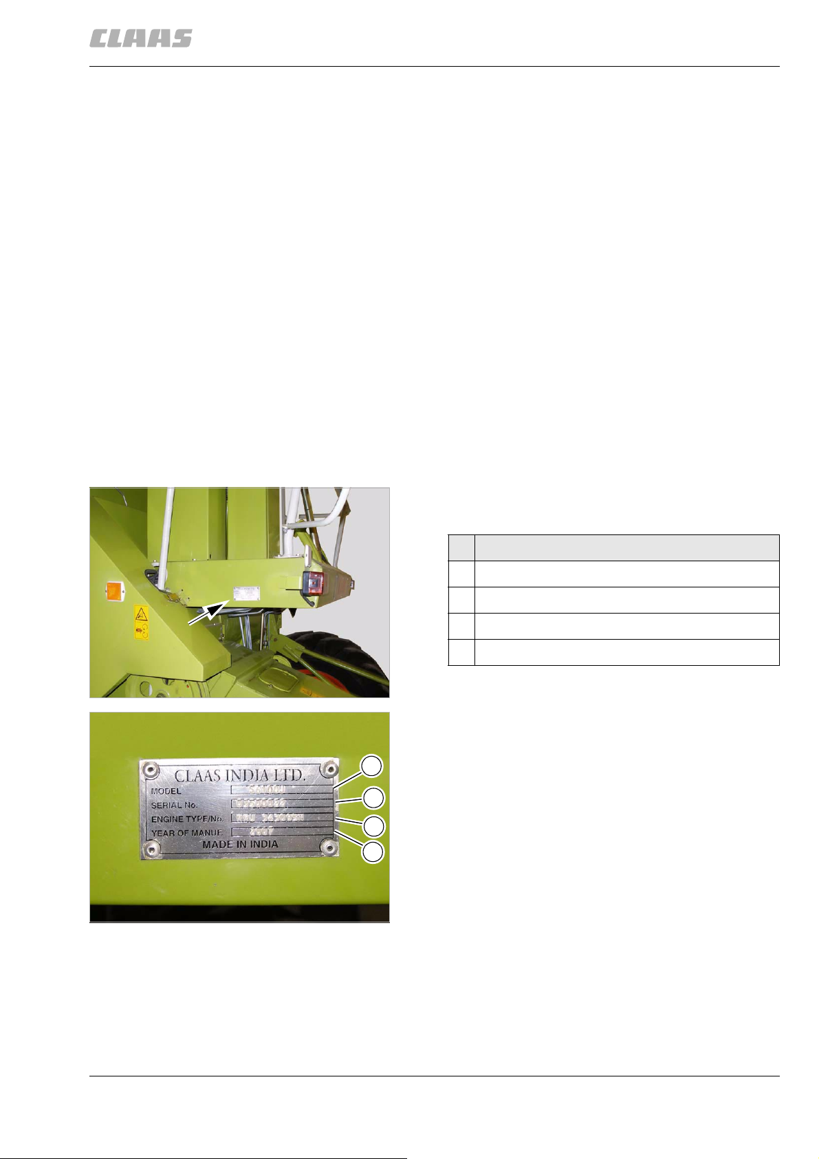
1.2.2 Machine identification plate
21339
1
2
3
4
The identification plate is affixed to the right-hand side
of the machine on the operator's platform.
Designation
1Type
2 Identification no. (machine number)
3 Type of diesel engine
4 Year of manufacture
1
2
21338
000 295 893 0 - BA CROP TIGER 30 - 12/07 17
Page 18
1 Introduction
1.2 Identification plates and identification numbers
1
21352
29483
In addition, the identification number of the machine is
stamped into the frame underneath the flap (1).
3
62312
1.2.3 Engine identification plate
The identification plate of the diesel engine is affixed
above the engine.
21341
4
18 000 295 893 0 - BA CROP TIGER 30 - 12/07
Page 19

2 Safety Rules
2 Safety Rules
2.1 General Information
29484
2.1 General Information
45097
2.1.1 General information
The CE mark and the enclosed declaration of conformity document that the self-propelled machine
fulfils the safety regulations of the EC Machinery
Directive.
Before putting the machine into operation, read and
follow the Operator's manual and the safety
instructions!
857
2.1.2 Important information
The instructions in this operator's manual must be read
and observed, in order to prevent danger to all persons, who operate, maintain, repair and inspect this
CLAAS product.
Please read, in particular, the sections "Safety rules",
"Before commissioning" and "Before putting the
machine into operation" in the machine operator's
manual.
The use of spare parts, accessories and ancillary
equipment that are not original CLAAS parts and not
tested and approved by CLAAS, can have a negative
impact on design specifications of the CLAAS machine
and its operational reliability and thereby impair active
and/or passive driving safety, as well as occupational
safety (accident prevention).
Insofar as damages are caused through the use of
non-CLAAS parts, accessories and ancillary equipment, any liability will be rejected by CLAAS.
858
2.1.3 Intended use
Both the front attachment and the machine are
designed solely for use in customary agricultural operations (intended use).
Use in any other way is considered as contrary to the
intended use. The manufacturer accepts no liability for
any damage or injury resulting from this misuse and
these risks must be born solely by the user.
Compliance and strict adherence to the conditions of
operation, service and repair as specified by the manufacturer also constitute essential elements for the
intended use.
This front attachment and the machine may be operated, serviced and repaired only by persons familiar
with all its particular characteristics and acquainted
with the relevant safety rules.
000 295 893 0 - BA CROP TIGER 30 - 12/07 19
Page 20

2 Safety Rules
2.1 General Information
29484
The accident prevention regulations, all other generally recognised regulations on safety and occupational
medicine and the road traffic regulations must be
observed at all times.
Any arbitrary modifications carried out on the front
attachment and on the machine will relieve the manufacturer of all liability for any resulting damage or
injury.
2413
2.1.4 Safety and accident prevention regulations
• In addition to the information in this operator's
manual, please refer to the general safety and
accident prevention regulations.
• Before putting the machine into operation, check it
for road and operational safety.
• Observe the respective regulations when using
public traffic routes.
• Before work commences, you must familiarise
yourself with all of the control mechanisms and
their function. Once you are driving it is too late.
• Before starting the diesel engine, you must ensure
that all safety devices are attached and in their
protective positions.
• Only start the diesel engine from the driver's seat.
The diesel engine must not be started by shortcircuiting the electrical connections on the starter,
because the machine may immediately start to
move.
• Before starting the diesel engine and before
switching on the machine:
- Ensure that there are no persons, children or
objects in the hazardous area.
- Look out for children.
- Signal by sounding the horn.
• Before pulling away in the machine:
- Ensure that there are no persons, children or
objects in the danger area.
- Ensure adequate visibility.
- Check the immediate vicinity for people and
children.
- Look out for children.
- Signal by sounding the horn.
• Do not let diesel engine run in enclosed spaces.
• The driver should not wear loosing clothing. Avoid
loose-fitting clothing.
• Caution is urged when handling fuel. – Increased
fire hazard. Never pour fuel in close proximity to
open flames or sparks that may cause ignition. Do
not smoke while filling the fuel tank.
• Before filling the fuel tank, always switch off the
diesel engine and remove the ignition key. Do not
fill the fuel tank in an enclosed space. Wipe up
spilled fuel immediately.
20 000 295 893 0 - BA CROP TIGER 30 - 12/07
Page 21

2 Safety Rules
2.1 General Information
29484
• To prevent a risk of fire, keep the machine clean.
• Caution is urged when handling brake fluid and
battery acids.
Toxic and corrosive.
• Ensure there is sufficient safety clearance in
areas with low-hanging power lines. You may
need to look out for radio antenna.
• The warning and information labels affixed to the
machine provide important information regarding
safe operation.
Compliance is for your own safety.
Replace damaged and illegible warning signs /
safety instruction stickers immediately.
If parts with warning signs / safety instruction
stickers are being replaced, ensure that the
appropriate warning signs / safety instruction
stickers are affixed to the new parts.
• Do not stay in the engine compartment while the
diesel engine is running.
• Ensure that the access ladder, the platform and
other access areas of the machine are always free
from oil and grease.
36687
2.1.5 General safety and accident prevention regulations for combine harvesters
• Never stand inside the range of rotation of the
unloading auger tube while the engine is running.
Do not allow any other persons to stand there as
well!
2.1.6 Prior to operation, general
• Observe the maximum permissible axle loads and
total weights.
• Before starting to drive and operate the forage
harvester, adjust the mirrors to give full vision of
the road and of the operating area behind.
• Before driving the forage harvester always check
brakes for correct function and regularly check the
level of the brake fluid. Only use the specified type
of brake fluid and change the brake fluid at the
recommended intervals.
Take care when handling brake fluid.
Toxic and corrosive!
- Dispose of used brake fluid in a way that is
harmless to the environment and in accordance
with existing anti-pollution regulations.
• The left and right brake pedals must be locked
together for transport and road travel so that both
front wheel brakes will be applied simultaneously.
• Projecting parts must be removed or adjusted to
within the normal width of the machine before driving on public roads and lanes.
• Before driving off, always check the front and rear
wheels for the correct tyre pressures!
2414
000 295 893 0 - BA CROP TIGER 30 - 12/07 21
Page 22

2 Safety Rules
2.1 General Information
29484
2416
2.1.7 Transporting passengers
• Only such persons may be transported on the
instructor's seat who provide instructions regarding the machine.
• The carrying of passengers is otherwise not
permitted.
2417
2.1.8 General driving operations
• When driving on the road with a raised front
attachment, the safety switch must be switched
off.
• Never leave the operator's platform while driving.
• The machine is only permitted to drive on public
streets and roads with an empty grain tank / loading hopper.
• On public streets and roads, front attachments
with finger bars, crop lifters or crop divider points
must be covered.
• Be particularly careful at railway crossings. If a
railway crossing cannot be crossed quickly
because of traffic or an obstruction and without
stopping, then you must stop in front of the St.
Andrew's cross. Otherwise, a railway crossing is
to be crossed without stopping.
• The driving behaviour of the machine is affected,
for example, by the road and by implements.
Therefore, adapt your driving style to the actual
terrain and ground conditions. Special care must
be taken when working and turning on a slope or
with a full grain tank / loading hopper. – Never shift
gears on a slope.
• When the diesel engine has stopped or when the
hydraulic steering fails, significantly more force is
required to steer.
• Immediately stop the machine if there is with any
kind of steering or brake problem. Have malfunctions corrected immediately.
62317
2.1.9 Automotive operation of combine harvester
• When travelling on public roads swing in the grain
tank unloading tube all the way.
• Existing traffic regulations must be observed.
3715
2.1.10 Driving operations on slopes
• On surfaces with an incline of over 7 %, you must
shift down the gears (diesel engine braking effect).
62324
2.1.11 Leaving the machine
• Prevent the machine from rolling when you leave
(parking brake, wheel chocks). Turn the engine
off, remove the ignition key and lock the cab, if
necessary.
22 000 295 893 0 - BA CROP TIGER 30 - 12/07
Page 23

2 Safety Rules
2.1 General Information
• Never leave the machine unattended when the
engine is still running.
• Before leaving the machine, lower the front
attachment completely.
2.1.12 Front attachment
• Only carry out work under raised front attachments if they are supported safely.
• Front attachments and feeder units, such as conveyors, rollers, chains, augers, reels and similar
cannot be fully secured using integral design features due to their function. Therefore, during
operation, keep a sufficient safety distance from
the moving parts. The sense of these instructions
applies to all other ancillary attachments.
2.1.13 Grain delivery
• The augers located inside the grain tank
cannot be shielded completely against accidental
contact due to their function.
• Before mounting or entering the grain tank, make
sure that no other person can restart the engine.
• Enter the grain tank only through the opening provided for this purpose.
2.1.14 Adjustment and maintenance work
29484
62327
36728
62347
The drives on the machine will not be automatically
secured from moving after the engine has been
switched off.
Moreover, when it comes to adjustments, it may be
necessary to turn the drives.
For these reasons the following precautions should be
observed:
• Before adjustment, cleaning and maintenance
operations and before correcting malfunctions:
- Switch off the threshing mechanism.
- Disengage the front attachment.
- Switch off the grain tank unloading mechanism.
- Stop the engine.
• Before adjustment, cleaning and maintenance
operations and before correcting malfunctions at
the hydraulic system, lower the front attachment
and/or feeder unit all the way.
• As a rule, always disconnect the cable from the
battery when working on the electrical system.
• Once the threshing unit has been switched off, the
drives will continue turning for a short period of
time. You must wait until all the drives have
stopped before carrying out any work.
• Please ensure that it is not possible for anyone to
accidentally start the machine or turn any of the
drives whilst work is being carried out.
000 295 893 0 - BA CROP TIGER 30 - 12/07 23
Page 24
2 Safety Rules
2.1 General Information
29484
• Escaping fluid (fuel or hydraulic oil) under high
pressure can penetrate the skin and cause serious injury. If any fluid is injected into the skin,
consult a doctor immediately as otherwise serious
infections may result.
• Repair work on the hydraulic system may only be
carried out by specialist workshops.
• Be careful when opening the radiator cap. The
radiator is under pressure when the engine is hot.
• Do not attempt to mount a tyre unless you have
the proper equipment and experience to perform
the job safely.
• Dispose of oil, fuel and filters in a way that is
harmless to the environment and in accordance
with existing anti-pollution regulations!
• Retighten the wheel nuts and wheel bolts
regularly!
62824
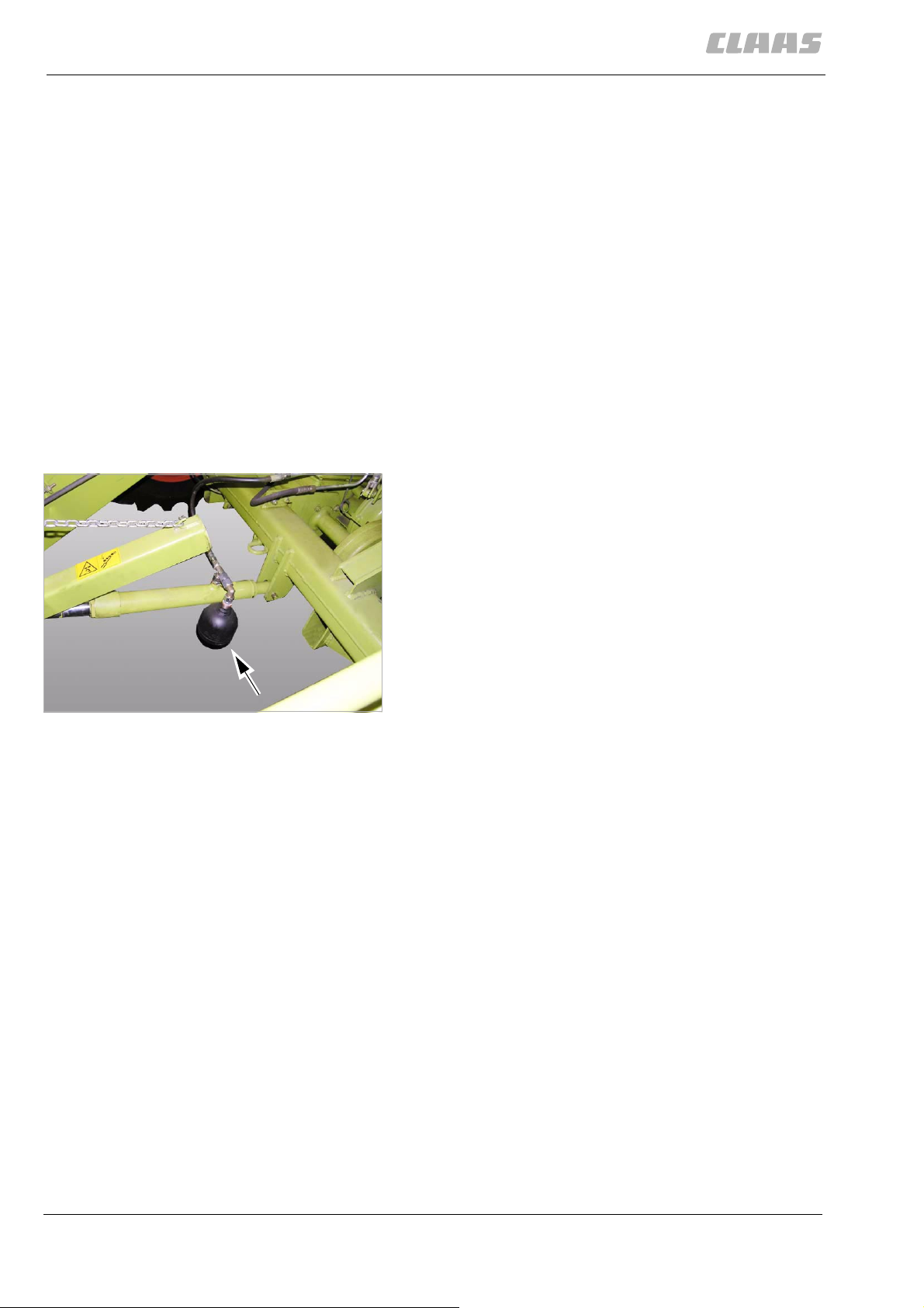
2.1.15 Accumulators
Be especially careful when working on hydraulic systems equipped with accumulators. Hydraulic systems
with accumulators are under high pressure!
21510
Only have qualified workshops carry out repair work on
the hydraulic system.
1
2425
2.1.16 Antifreeze
Antifreeze is easily inflammable!
Keep antifreeze away from children!
Vapours may cause sleepiness and a dazed feeling.
Repeated contact may cause chapped or rough skin.
The following problems may arise:
• Irritation of the eyes
• Irritation of the respiratory tract
• Headache
•Giddiness
Effects on the central nervous system in case of high
doses:
• Difficulty in breathing
• Unconsciousness
Swallowing:
• Sickness
• Vomiting
24 000 295 893 0 - BA CROP TIGER 30 - 12/07
Page 25

2 Safety Rules
2.1 General Information
• Liver damage
Antifreeze must not come in contact with the
environment.
– Collect antifreeze in a suitable container!
– Dispose of antifreeze in a way that is harmless to
the environment and in accordance with existing
anti-pollution regulations.
2.1.17 First aid measures
Inhaling:
– Make the person inhale fresh air and consult a
doctor, depending on the symptoms.
– Remove the person from the hazard area.
Eye contact:
– Thoroughly flush with water for several minutes. If
necessary, consult a doctor.
Skin contact:
29484
2427
– Thoroughly clean with plenty of water and soap
and remove polluted and soaked clothing immediately, consult a doctor if skin is irritated (redness
etc.).
Swallowing:
– Do not cause vomiting, consult a doctor
immediately.
62390
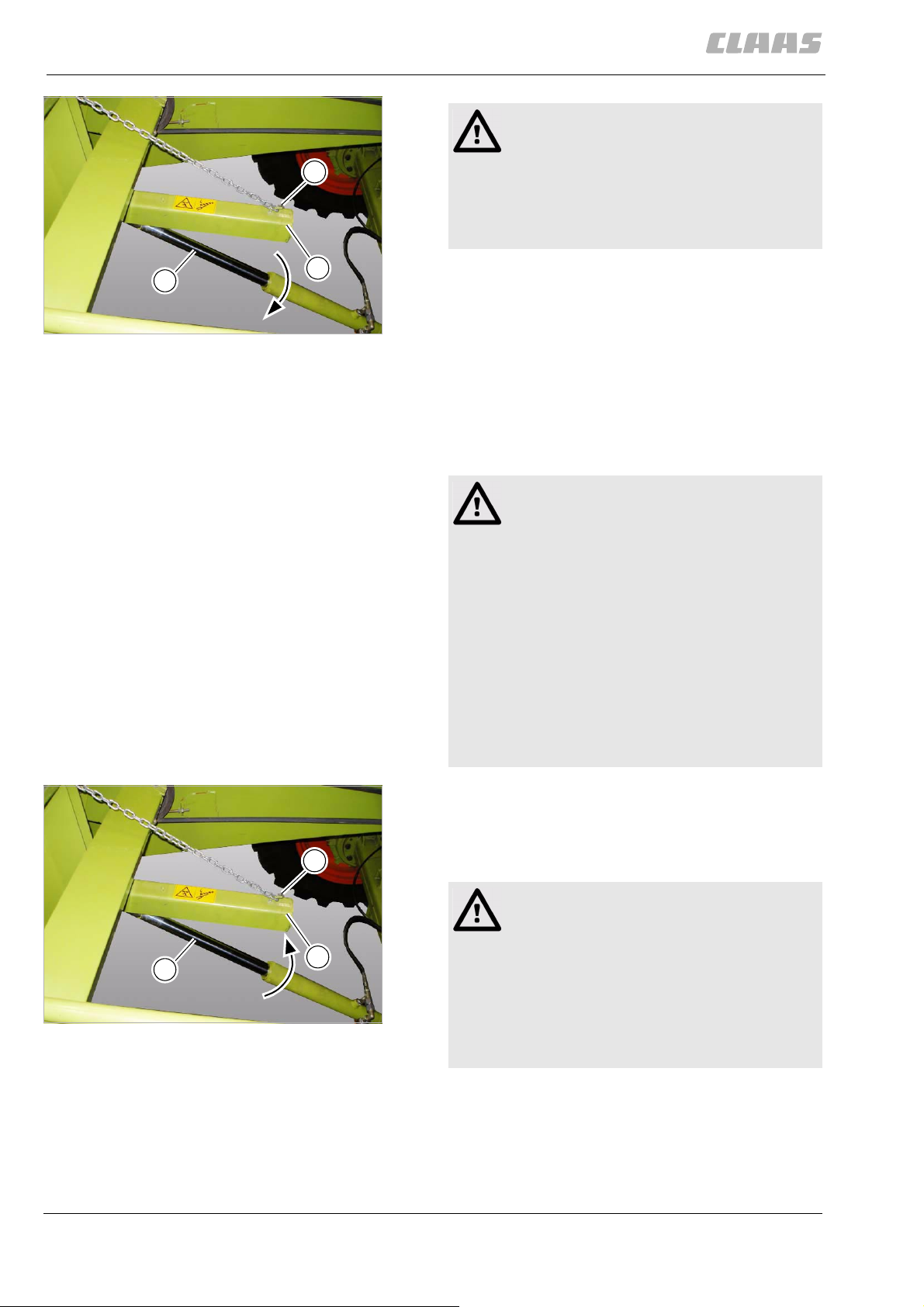
2.1.18 Applying the feeder housing safety lock
The engaged safety lock prevents an uncontrolled
drop of the feed rake conveyor and the mounted front
attachment.
Danger!
Only undertake repair, maintenance and
cleaning work and the correction of malfunctions when the machine is stopped.
Death or serious injuries!
– Diesel engine OFF.
– Apply the parking brake.
– Remove ignition key.
– Loosen and remove the cable clamps on
the battery.
– Secure the machine with wheel chocks.
– Ensure that the machine cannot be put
into operation by a third party.
000 295 893 0 - BA CROP TIGER 30 - 12/07 25
Page 26
2 Safety Rules
2.1 General Information
29484
Danger!
The front attachment and / or the feeder unit
2
may drop in an uncontrolled way.
Death or serious injury.
– Keep a safe distance from the hazard
area.
3
1
2
21367
– Fully lower the reel.
– Raise the feeder unit all the way.
– Detach the safety lock (1) from the chain at (2)
and fold down onto the piston (3) of the hydraulic
cylinder.
– Lower the feeder unit onto the secured safety
lock (1).
62397
2.1.19 Disengaging feed rake conveyor safety lock
Danger!
Only undertake repair, maintenance and
cleaning work and the correction of malfunctions when the machine is stopped.
Death or serious injuries!
– Diesel engine OFF.
– Apply the parking brake.
– Remove ignition key.
– Loosen and remove the cable clamps on
the battery.
– Secure the machine with wheel chocks.
– Ensure that the machine cannot be put
into operation by a third party.
– Fully lower the reel.
– Raise the feeder unit all the way.
– Lift the safety lock (1) and hang into the chain at
2
(2).
Danger!
The front attachment and / or the feeder unit
may drop in an uncontrolled way.
3
1
Death or serious injury.
– Support front attachment and / or feeder
3
21367
unit.
– Keep a safe distance from the hazard
area.
26 000 295 893 0 - BA CROP TIGER 30 - 12/07
Page 27
2 Safety Rules
2.1 General Information
29484
62406
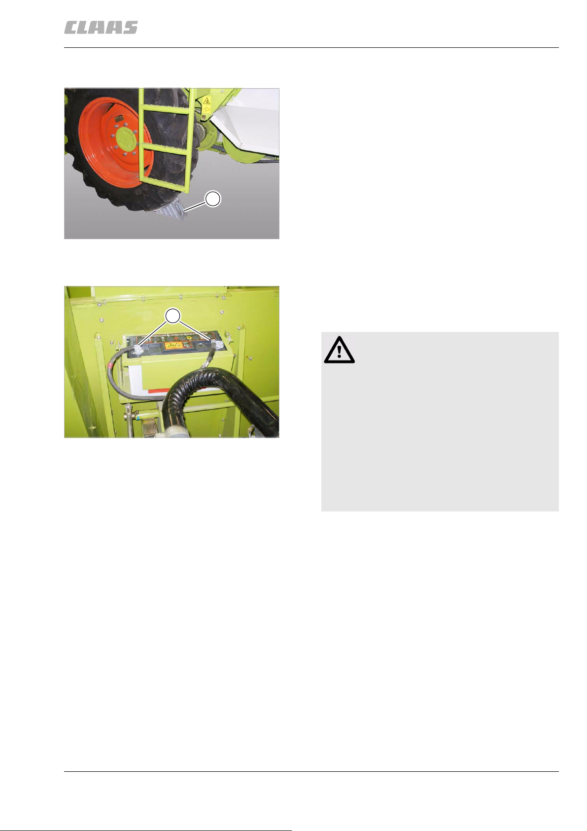
2.1.20 Wheel chocks
The wheel chocks are not included in the scope of
delivery of the machine.
– Place the wheel chock (1) on both sides of the
machine tightly in front of or behind the drive
wheel, depending on the slope.
The machine has been secured against rolling.
1
4
21394
65683
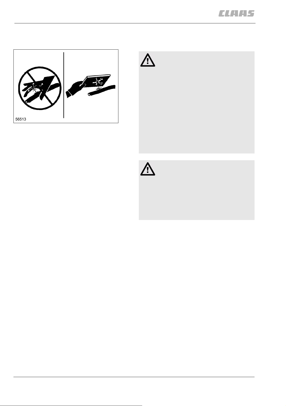
2.1.21 Disconnecting the battery
In order to interrupt the power supply to the machine,
loosen and remove the cable clamps (1) from the
1
battery.
21428
WARNING:
Work on the electrical system.
Machine damage.
– Before starting work, disconnect the cable
from the negative terminal first and then
from the positive terminal of the battery.
5
– When wrk is complete, first connect the
positive terminal and then the negative
terminal to the battery.
– Always disconnect the cables from the
alternator and battery before performing
electrical welding work on the machine
and the front attachment.
Disconnect the battery daily after using the machine
and in case of an emergency.
Do not disconnect the battery when the diesel engine
is running.
000 295 893 0 - BA CROP TIGER 30 - 12/07 27
Page 28
2 Safety Rules
2.1 General Information
740
2.1.22 Danger of injury due to escaping hydraulic liquid
Danger!
Liquids under high pressure.
Liquids penetrate the skin and cause serious
injury.
– Only have authorised and qualified work-
shops carry out work on the hydraulic
system.
– Check hose lines at regular intervals.
Search for leaks using a piece of wood or
6
cardboard.
Ensure that the oil jet will not be directed
towards your body.
– Replace any damaged hose lines.
– Replace hose lines 6 years after the date
of manufacture at the latest.
29484
36998
Danger!
Dealing incorrectly with injuries due to hydraulic fluids.
Death or serious injury.
Even a pinhole can result in severe injuries.
– If hydraulic fluid gets in the skin or eyes,
have the injury treated by a medical spe-
cialist immediately.
2.1.23 Attaching finger bar safety bar
For transporting the front attachment, the safety bar
must be placed on the finger bar.
In addition, the safety bar must be fitted during all
maintenance and repair work near the knives or the
feed mechanism.
On front attachments without a crop lifter fitted, the
safety bar must be attached directly on the knives.
– Raise the front attachment until the finger bar is in
a well-accessible working height.
– Raise the reel completely.
– Putting the machine out of operation.
63221
28 000 295 893 0 - BA CROP TIGER 30 - 12/07
Page 29
2 Safety Rules
2.1 General Information
Danger!
Only undertake repair, maintenance and
cleaning work and the correction of malfunctions when the machine is stopped.
Death or serious injuries!
– Diesel engine OFF.
– Apply the parking brake.
– Remove ignition key.
– Loosen and remove the cable clamps on
the battery.
– Secure the machine with wheel chocks.
– Ensure that the machine cannot be put
into operation by a third party.
Danger!
Front attachment, reel and feeder unit may
drop in an uncontrolled way.
29484
Death or serious injury.
– Fit the safety locks.
– Keep a safe distance from the hazard
area.
Warning!
Sharp edges and sharp-edged machine parts
Slight injuries.
– Wear safety gloves.
– Wear a safety hat.
– Use the tension springs to secure safety bar (1) to
1
the finger bar.
7
21635
000 295 893 0 - BA CROP TIGER 30 - 12/07 29
Page 30
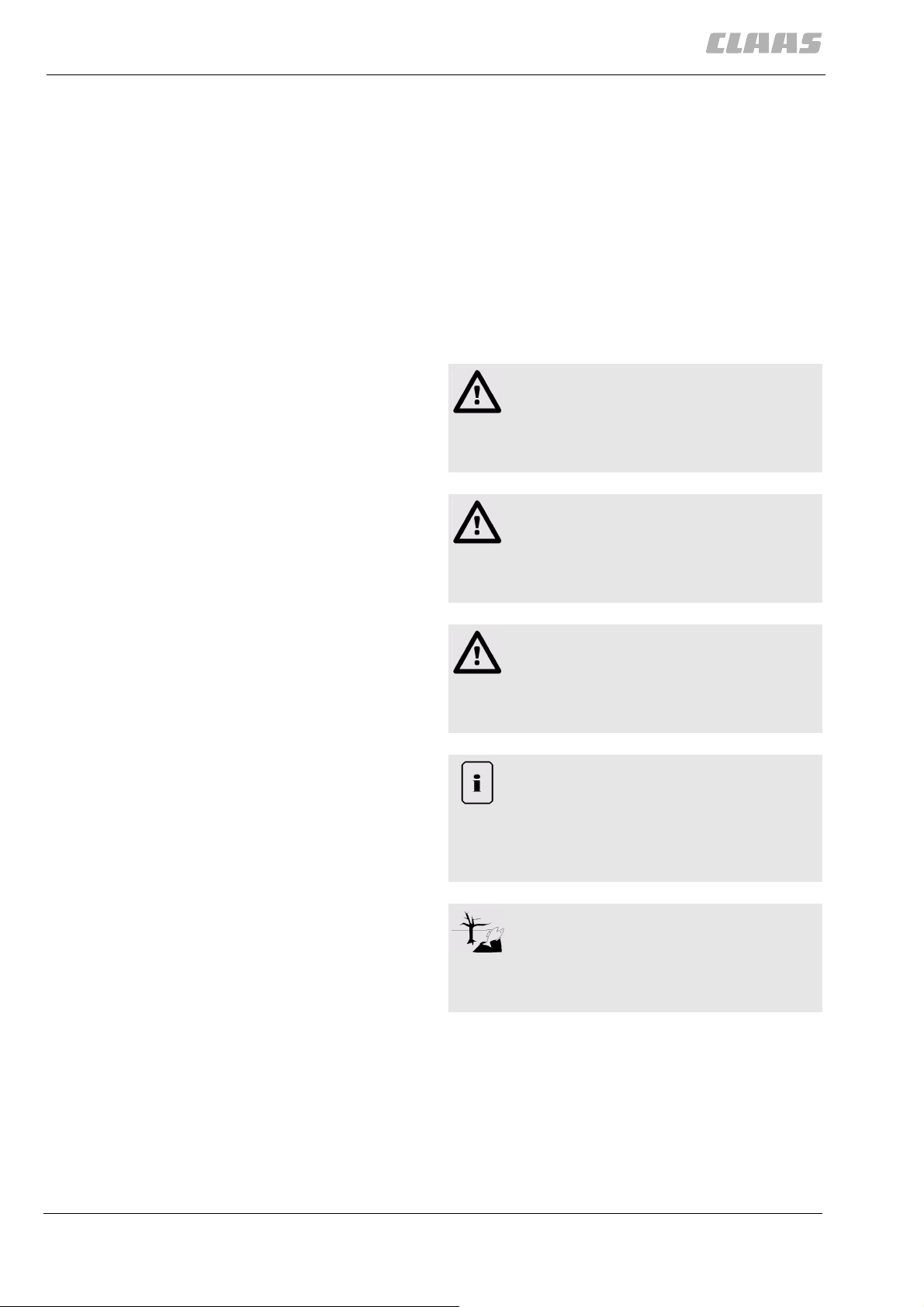
2 Safety Rules
2.2 Safety rules
29484
2.2 Safety rules
Before putting the machine into operation, read and
follow the Operator's manual and the safety
instructions!
76
2.2.1 Identification of warning and danger signs
All parts of this operator's manual having to do with
your safety or the safe operation of the front attachment or the machine are marked with the following
signs. Please pass on all safety precautions to any
other users of the machine as well.
Danger!
Nature and source of danger
Consequences: death or serious injury
– Countermeasures
Warning!
Nature and source of danger
Consequences: injuries
– Countermeasures
Caution!
Nature and source of danger
Consequences: material damage
– Countermeasures
Note!
Nature and source of information
Consequences: enhanced machine economy
or easy assembly
–Measures
Environment!
Nature and source of danger
Consequences: damage to the environment
– Countermeasures
30 000 295 893 0 - BA CROP TIGER 30 - 12/07
Page 31

2 Safety Rules
2.3 Safety decals
29484
2.3 Safety decals
859
2.3.1 General instructions for warning signs
The danger zones on the machine or on the front
attachment which cannot be eliminated by design or
protective measures, are identified by safety decals.
These safety decals help to alert persons to hazards
which can cause personal injury.
The safety decals consist of two components:
– Part 1 shows the risk of injury in a warning
triangle.
– Part 2 shows how injury and accidents can be pre-
vented by appropriate actions.
The pictures on the safety decals consist of generally
understandable pictograms. As far as possible, the
safety decals must be located in close proximity to the
hazardous area.
The original CLAAS safety decals are equipped with
the CLAAS part number and the date of manufacture.
The positioning and meanings of the safety decals are
explained below:
– When ordering, please use the 10-digit CLAAS
part number given ahead of every safety decal,
– the safety decal number given in ( ) shows the
correct position of the safety decals in the associated picture,
– followed by an explanation of the safety decal
graphics in text form.
Danger!
Hazard points on the machine.
Death or serious injury!
– Hazard warning signs / safety decals that
are damaged or unrecognisable must be
replaced immediately by new ones.
– When parts that have hazard warning
signs / safety decals are replaced, always
make sure to attach the relevant new haz-
ard warning signs / safety decals to
each new part.
000 295 893 0 - BA CROP TIGER 30 - 12/07 31
Page 32

2 Safety Rules
2.3 Safety decals
29484
65979
2.3.2 Front attachment
000 516 028 0 (11)
11
8
21505
11
31
10
Do not open or remove safety shields while engine is
running.
9
21506
000 516 040 0 (31)
11
21505
12
Stay clear of front attachment. Disengage front attachment drive, shut off engine, and remove key before
servicing or unclogging front attachment.
32 000 295 893 0 - BA CROP TIGER 30 - 12/07
Page 33

31
2 Safety Rules
2.3 Safety decals
29484
000 516 453 0 (31)
17
21463
21431
13
15
Stay clear of front attachment. Disengage front attach-
14
ment drive, shut off engine, and remove key before
servicing or unclogging front attachment.
62434
2.3.3 Engine
000 516 034 0 (17)
16
Do not open or remove safety shields while engine is
running.
000 295 893 0 - BA CROP TIGER 30 - 12/07 33
Page 34

2 Safety Rules
2.3 Safety decals
29484
62437
2.3.4 Chassis
000 516 047 0 (40)
40
17
21430
40
21432
19
Use wheel chock before machine is uncoupled or
parked.
18
34 000 295 893 0 - BA CROP TIGER 30 - 12/07
Page 35

22
2 Safety Rules
2.3 Safety decals
29484
62821
2.3.5 Drives
000 516 039 0 (22)
20
21339
22
22
23
Do not open or remove safety shields while engine is
running.
21
21508
22
21509
000 295 893 0 - BA CROP TIGER 30 - 12/07 35
Page 36

2 Safety Rules
2.3 Safety decals
24
29484
62497
2.3.6 Cab / Operator's platform
000 516 041 0 (24)
24
21435
25
Never reach or climb into grain tank while engine is
running.
000 515 209 1 (2)
2
27
21435
26
Carefully read operator’s manual before handling the
machine. Observe instructions and safety rules when
operating.
36 000 295 893 0 - BA CROP TIGER 30 - 12/07
Page 37

33
2 Safety Rules
2.3 Safety decals
29484
000 514 895 1 (33)
28
21430
29
Shut off engine and remove key before performing
maintenance or repair work.
34
000 516 044 0 (34)
30
21430
31
Do not ride on platform or ladder.
000 295 893 0 - BA CROP TIGER 30 - 12/07 37
Page 38

2 Safety Rules
2.3 Safety decals
13
29484
62528
2.3.7 Feeder unit
000 516 414 0 (13)
15
21367
21448
32
34
33
Secure lifting cylinder with locking device before getting in hazardous area.
000 514 901 1 (15)
35
Do not open or remove safety shields while engine is
running.
62530
2.3.8 Threshing mechanism
000 516 063 0 (16)
16
37
21448
36
Never reach into rotating auger.
38 000 295 893 0 - BA CROP TIGER 30 - 12/07
Page 39

15
2 Safety Rules
2.3 Safety decals
29484
000 514 901 1 (15)
38
21474
15
32
21502
21352
39
41
40
Do not open or remove safety shields while engine is
running.
62819
2.3.9 Crop receptacle / straw receptacle
000 514 897 1 (32)
42
Danger - flying objects; keep safe distance from the
machine as long as the engine is running.
000 295 893 0 - BA CROP TIGER 30 - 12/07 39
Page 40

2 Safety Rules
2.3 Safety decals
29484
62815
2.3.10 Grain delivery
000 516 063 0 (16)
16
16
16
21498
21499
43
44
45
Never reach into rotating auger.
000 516 033 0 (16)
46
21501
16
48
Never reach into rotating auger.
47
21502
40 000 295 893 0 - BA CROP TIGER 30 - 12/07
Page 41

15
2 Safety Rules
2.3 Safety decals
29484
000 514 901 1 (15)
49
21507
50
Do not open or remove safety shields while engine is
running.
000 295 893 0 - BA CROP TIGER 30 - 12/07 41
Page 42

3 Sectional view of machine
3.1 CROP TIGER 30
3 Sectional view of machine
3.1 CROP TIGER 30
3.1.1 Overview of machine front and left side
29485
63046
5
6
1
Designation
1 Front attachment
3
10
2
7
9
8
4
21578
1
2 Feeder unit
3 Operator's platform
4 Ladder to the operator's platform
5 Grain tank loader
6Grain tank
7 Grain tank unloading tube
8Drive axle
9 Rear axle
10 Side flap of main drive / fuel filler neck
42 000 295 893 0 - BA CROP TIGER 30 - 12/07
Page 43

3.1.2 Overview of machine rear and right side
2
1
3
5
3 Sectional view of machine
3.1 CROP TIGER 30
29485
63074
Designation
1 Diesel engine
2 Rotary chaff screen
3 Tailgate
4 Drives side flaps
5 Rear hood
4
21585
2
000 295 893 0 - BA CROP TIGER 30 - 12/07 43
Page 44

3 Sectional view of machine
3.1 CROP TIGER 30
3.1.3 Overview of front attachment
5
4
29485
66101
1
Designation
1Reel
2 Crop divider
3 Finger bar
4 Reel cylinder (raise/lower)
5 Intake auger
2
3
22428
3
44 000 295 893 0 - BA CROP TIGER 30 - 12/07
Page 45

4 Technical specifications
4.1 CROP TIGER 30 - TYPE 35
4 Technical specifications
4.1 CROP TIGER 30 - TYPE 35
4.1.1 General information
The machine used for determining the technical specifications was equipped with tyres 13.6-28 and 7.5-16,
4-cylinder diesel engine, a full fuel tank and a roof.
4.1.2 Front attachment
Designation
Cutting width 2.7 m
Intake auger, rice Coated auger spirals
Reel drive Mechanical V-belt variable speed drive
Reel speed 12 - 49 rpm
Reel height adjustment hydraulic
29486
63224
65984
Hydraulic fore and aft reel adjustment mechanical
4.1.3 Engine
Designation
Engine manufacturer Perkins
Engine type 1104A-44
Cubic capacity 4.4 litres
Maximum no-load speed 2310
Rated speed 2200 rpm
Minimum no-load speed 1000
Engine power at rated speed 2200 ± 10 rpm
Output (ISO TR 14396) 57 (77), kW (hp)
Coolant approx. 18.0 litres
Alternator 65 A / 12 V
Fuel tank capacity 100 litres
+20/-30
+20/-30
rpm
rpm
63157
000 295 893 0 - BA CROP TIGER 30 - 12/07 45
Page 46

4 Technical specifications
4.1 CROP TIGER 30 - TYPE 35
4.1.4 Chassis
Designation
Ground drive mechanical, hydraulically adjustable variable speed
drive
Manual gearbox 3 forward gears and 1 reverse gear
Forward ground speed 1st gear from 1.3 to 3.4 km/h
2nd gear from 2.5 to 6.8 km/h
3rd gear from 6.6 to 18.2 km/h
Reverse ground speed R gear from 2.7 to 7.4 km/h
Front wheel drive Final drives running in oil
4.1.5 Chassis track width
29486
68476
69162
A Width between the tyres
B Track width
C Width over tyres
Axle Tyres A B C
mm mm mm
Drive axle 13.6-28 AS 1822 2182 2542
Rear axle 7.50-16 Truck 1140 1354 1700
4.1.6 Brake
Designation
Brake Fluid pressure brakes, designed with an independent
brake system
Parking brake mechanical, independent
4.1.7 Tyre pressures
Designation bar / psi
69269
68787
Front tyres 13.6-28 1.9 / 28
Rear tyres 7.50-16 2.8 / 40
69270
4.1.8 Steering
Designation
Steering, type hydrostatic
46 000 295 893 0 - BA CROP TIGER 30 - 12/07
Page 47

4 Technical specifications
4.1 CROP TIGER 30 - TYPE 35
4.1.9 Drives
Designation
Front attachment: intermediate drive shaft speed 1140± 10 rpm
4.1.10 Electric system / Electronics
Designation
Battery 12 volts, 80 Ah
4.1.11 Feeder unit
Designation
Feed rake conveyor Feeder chain
Cutting height From -28 mm to maximum +690 mm
29486
63232
69164
69170
Clearance height (up to bottom edge of cutterbar
710 mm
skids)
Cutterbar clutch V-belt clutch
4.1.12 Threshing mechanism
Designation
Stone trap As standard
Axial and tangential separating system Lateral mounted rotor, one-piece threshing concave,
cylindrical separating cage
Threshing concaves: 1 section, width 575 mm,
Adjustable on the right-hand side of the rotor housing
– Grain N10 (10 x 34)
– Soya / maize N18 (18 x 34)
– Rice Spike tooth concave
Disawning bars 2 disawning bars
Separating cage Cylinder-shaped, lower half with perforations 20 x 40
67617
Threshing drum clutch V-belt clutch
000 295 893 0 - BA CROP TIGER 30 - 12/07 47
Page 48

4 Technical specifications
4.1 CROP TIGER 30 - TYPE 35
4.1.13 Separation
Designation
Rotor Threshing and separating drum:
Diameter 450 mm
Width of the threshing area 575 mm
Width of the separating area 1225 mm
– Grain equipment 8 rasp bars, 4 saw-tooth separating bars
– Rice equipment 8 threshing tooth bars, 4 saw tooth separating bars
Speed adjustment 5 speeds by changing V-belt pulleys: 500, 630, 803,
1013, 1282 rpm
4.1.14 Cleaning unit
Designation
29486
68477
21325
Forced air cleaning Paddle-type cleaning fan
Wind quantity 2 speeds by changing the V-belt pulleys: 1343 and
1505 rpm
Sieve pan one-piece
Upper sieve Long-lipped frogmouth sieve
Lower sieve Short-lipped frogmouth sieve
Total sieve area 1.56 m²
4.1.15 Crop receptacle / straw receptacle
Designation
Straw receptacle on the left next to the machine
4.1.16 Grain delivery
Designation
Returns Return flow to the back collecting auger
Grain tank capacity
1500 litres (approx. 1.1 t wheat)
21269
21273
basis for calculation in t = litre weight of 780 g/l
Unloading tube mechanically swivelling
48 000 295 893 0 - BA CROP TIGER 30 - 12/07
Page 49

4.1.17 Attachment parts / machine body dimensions
4 Technical specifications
4.1 CROP TIGER 30 - TYPE 35
29486
63240
B Width of right side of front attachment to the unloading tube
rotating gear
Transport
position
3100 mm * 3100 mm
Working
position
* When crop dividers are installed, the displayed measurement for the outer deflector must be added.
H1 Height of bottom edge of the grain tank unloading tube – approx. 2100 mm
H2 Height of top edge of grain tank 2250 mm 2250 mm
H3 Height of top edge of grain elevator 2980 mm 2980 mm
H4 Height of top edge of roof 3550 mm 3350 mm
L1 Length of basic machine without front attachment 3720 mm –
L2 Length of basic machine with front attachment without crop
5750 mm –
divider
L3 Length of basic machine with front attachment with crop
6850 mm 6810 mm
dividers
000 295 893 0 - BA CROP TIGER 30 - 12/07 49
Page 50

4 Technical specifications
4.1 CROP TIGER 30 - TYPE 35
4.1.18 Attachment parts / machine body weights
Designation
Empty weight * 4485 kg
Front attachment 850 kg
2 short crop dividers +37 kg
2 rice crop dividers +10 kg
Rear straw receptacle (lateral straw conveyor belt) +70 kg
Straw chopper +80 kg
* Unladen weight with a full fuel tank and no front attachment.
29486
63243
50 000 295 893 0 - BA CROP TIGER 30 - 12/07
Page 51

5 Structure and function
5.1 CROP TIGER 30
5.1.1 Structure of the machine
5 Structure and function
5.1 CROP TIGER 30
29487
63136
Arrow Designation
Harvested crop
Grain, chaff and broken straw
Grain
Returns
Straw
Chaff
21608
63134
5.1.2 Working mode of the machine
Front attachment
Crop dividers separate the crop to be left standing
from the crop to be cut.
Crop lifters ensure zero-loss of down grain pick-up and
cut losses due to hanging crop are prevented.
1
000 295 893 0 - BA CROP TIGER 30 - 12/07 51
Page 52

5 Structure and function
5.1 CROP TIGER 30
29487
The reel guides the harvested crop into the intake
auger. The harvested crop, which is conveyed through
the intake auger spirals to the centre of the cutterbar,
is guided via the conveyor chains of the feeder unit to
the threshing mechanisms. Foreign objects are caught
by the stone trap. Damage to the threshing mechanisms are largely avoided by this.
Threshing and separating mechanism
The threshing and separating rotor and the threshing
and separating cage are used for threshing and separation. The right-hand section of the cage (approx. 1/3)
is the threshing area, consisting of an adjustable open
threshing concave in which the main threshing process
takes place. Rasp bars on the threshing section, tined
reaping bars on the separating section of the rotor and
twisted bars on the inside of the separating cage move
the material in a spiral shape around the rotor to the
left. The crop swirls around several times through the
cage, in order to achieve a gentle and thorough threshing and separation.
The earth on the grain along with the chaff and broken
straw is separated in the threshing concave and falls
into the trough of the front and rear collecting auger
under the separating cage.
The separating section of the rotor separates out the
grain which is still in the straw. The grain separated
here is also fed into the trough of the front and rear collecting auger. The straw is laid out on the field either
through the straw discharge opening on the left of the
machine or through a lateral straw conveyor belt
behind the machine.
Cleaning unit
The grain chaff broken straw mixture, which is conveyed from the auger spirals of the front and back
collecting auger to the middle, is thrown by the conveyer paddles of the front and back collecting auger
onto the preparation floor.
Through the swinging movement the grain chaff broken straw mixture is broken up on the preparation floor
and supplied to the sieves simultaneously.
The air blast produced by the cleaning fan carries all of
the light parts (chaff) out the rear of the machine. The
grain fall through the upper and lower sieve into the
trough of the grain auger and are conveyed by the
grain elevator into the grain tank.
All parts that are heavier than the grain and larger than
the chaff are fed via the upper and lower sieve into the
trough of the returns auger. Here they are fed via the
returns elevator back to the collecting auger for
renewed cleaning.
After swinging out the grain tank unloading tube, the
grain tank can be quickly emptied directly into a waiting trailer or one that is being towed alongside.
52 000 295 893 0 - BA CROP TIGER 30 - 12/07
Page 53

6 Prior to each operation
6 Prior to each operation
6.1 General Information
29488
6.1 General Information
37391
6.1.1 General warnings
In the following sections of this chapter, the general
warnings below are referred to by means of
instructions.
Danger!
Carry out repair, maintenance and cleaning
work and remove malfunctions only with the
machine shut down.
Death or serious injury.
– Diesel engine OFF.
– Engage the parking brake.
– Remove the ignition key.
– Remove the key of the battery isolating
switch.
– Secure machine by means of wheel
chocks.
– Ensure that the machine cannot be put
into operation by third-party persons.
6.1.2 Check list for daily operation
The following must be carried out every time before
putting the machine into operation.
– Complete all necessary steps according to the
maintenance schedule.
Chassis
– Check the air pressure of the tyres.
63142
000 295 893 0 - BA CROP TIGER 30 - 12/07 53
Page 54

7 Prior to initial operation
7.1 General Information
7 Prior to initial operation
29489
7.1 General Information
63349
7.1.1 General warnings
In the following sections of this chapter, the general
warnings below are referred to by means of
instructions.
Danger!
Only undertake repair, maintenance and
cleaning work and the correction of malfunctions when the machine is stopped.
Death or serious injuries!
– Diesel engine OFF.
– Apply the parking brake.
– Remove ignition key.
– Loosen and remove the cable clamps on
the battery.
– Secure the machine with wheel chocks.
– Ensure that the machine cannot be put
into operation by a third party.
Danger!
Front attachment, reel and feeder unit may
drop in an uncontrolled way.
Death or serious injury.
– Fit the safety locks.
– Keep a safe distance from the hazard
area.
54 000 295 893 0 - BA CROP TIGER 30 - 12/07
Page 55

7 Prior to initial operation
7.1 General Information
7.1.2 Initial operation check list
The following must be done before putting the
machine into operation.
– Complete all necessary items on the checklist for
daily putting the machine into operation.
– Observe instructions for loading and tying down
the machine.
– Clean the machine to protect it against salt dam-
age after sea travel or road travel involving wintery
road conditions.
Front attachment
– Align the front attachment.
Engine
– Check the air filter for correct seating.
– Check the engine oil level.
– Check the cooling water level.
29489
63371
Chassis
– Check the tyre pressure and correct if necessary.
– Check condition and permissibility of tyres.
– If necessary convert the rear axles / rear wheel
drive axles from transport position to working
position.
– If necessary adjust the wheel track for the given
tyres.
– Check tightening values of wheel fixing elements
and correct if necessary.
– Check oil level in all gearboxes and refill if
necessary.
Brake
– Check the brake fluid level and refill if necessary.
Drives
– Check all belt tensions and adjust if necessary.
– Check safety devices and put in their protective
position if necessary.
– Check the oil level in all gearboxes and refill if
necessary.
Hydraulic system
– Check hydraulic oil level and tightness of hydrau-
lic system.
Electrical / electronic equipment
– Top up and charge the battery if necessary.
000 295 893 0 - BA CROP TIGER 30 - 12/07 55
Page 56

7 Prior to initial operation
7.2 Front attachment
1
3
29489
7.2 Front attachment
63407
7.2.1 Aligning the front attachment
– Note the general warnings at the beginning of the
chapter "Prior to initial operation".
1
1
21448
– Making sure that the air pressure of all tyres corre-
sponds to the details in the section Technical
specifications.
– Drive the machine on level ground.
– Lower the front attachment until a skid touches the
ground.
– Check whether the front attachment is aligned
parallel to the ground.
– If necessary, align the front attachment.
- Loosen the nut (2) on each side of the feeder
unit.
- Loosen the bolts (3) on both sides of the feeder
unit.
- Align the front attachment on both sides of the
feeder unit using the bolt (1).
- Tighten the bolts (3) and the nuts (2) on both
sides of the feeder unit.
2
1
21693
2
56 000 295 893 0 - BA CROP TIGER 30 - 12/07
Page 57

7 Prior to initial operation
7.2 Front attachment
29489
66116
7.2.2 Fitting the crop dividers
– Note the general warnings at the beginning of the
chapter "Prior to initial operation".
Designation Number
1 Right crop divider 1
2 Left crop divider 1
3 Flat-headed screw M8 x 16 6
Hex. nut M8 6
Contact washer A8 6
4 Hexagon head bolt M12 x 25 6
Hex. nut M12 6
Contact washer A 12 6
– Bolt the crop divider (1) onto the right-hand side of
the front attachment.
4
1
4
3
22456
3
3
4
22457
– Bolt the crop divider (2) onto the left-hand side of
the front attachment.
000 295 893 0 - BA CROP TIGER 30 - 12/07 57
Page 58

8 Overview of controls
8.1 Cab / Operator's platform
8 Overview of controls
8.1 Cab / Operator's platform
8.1.1 Operator’s platform overview
3
29490
63177
16
14
13
Designation
12
4
5
2
9
10
11
6
8
17
1
7
15
21618
1
1 Operator’s seat
2 Steering wheel
3 Lever for the indicator / horn
4 Clutch pedal
5 Brake pedal
6 Control panel
7 Central electrics
8 Ignition switch
9 Lever to raise/lower the reel
10 Lever for the ground speed
11 Lever to raise/lower the front attachment
12 Lever to switch the threshing mechanism ON/OFF
13 Lever to switch the front attachment ON/OFF
14 Lever to switch grain tank unloading ON/OFF
58 000 295 893 0 - BA CROP TIGER 30 - 12/07
Page 59

Designation
15 Lever for the diesel engine speed
16 Lever for the gear shift mechanism
17 Lever for the parking brake/container for brake fluid
8.1.2 Switch console
8 Overview of controls
8.1 Cab / Operator's platform
29490
63188
9
6
7
8
5
1
4
2
3
10
21620
2
Designation
1 Hour meter for the diesel engine
2 Rotary switch for the driving lights
3 Rotary switch for the work lights
4 Indicator for air filter control
5 Indicator for the battery
6 Indicator for the cooling water temperature of the diesel engine
7 Indicator for oil pressure in the diesel engine
8 Indicator for the indicator lights
9 Information label for the gear shift mechanism
10 Hazard warning flasher switch
000 295 893 0 - BA CROP TIGER 30 - 12/07 59
Page 60

8 Overview of controls
8.1 Cab / Operator's platform
1
21627
8.1.3 Ignition switch
Caution
When operating or starting up the machine
when there is a problem with the diesel
engine.
Damage to the diesel engine.
3
Position
0 Ignition OFF
1 Ignition ON
29490
63199
– If a problem occurs with the diesel
engine, switch it off immediately or do not
switch it on.
– Correct the problem immediately or notify
an authorised specialist workshop.
Function
2 Pre-heat diesel engine
3 Start diesel engine
63193
8.1.4 Foot brake
The foot brake can be used both as a conventional
brake and as an independent brake.
Danger!
When using the independent brake on public
streets and roads.
Death or serious injuries!
– Before driving on public streets and
roads, couple the pedals of the foot brake
together.
– Only use the independent brake in the
field.
The independent brake serves for handling tight bends
or as a steering aid on muddy ground.
60 000 295 893 0 - BA CROP TIGER 30 - 12/07
Page 61

8 Overview of controls
8.1 Cab / Operator's platform
29490
The brake settings are as follows:
• Conventional brake with coupled brake pedal (1).
1
4
21622
• Independent brake with uncoupled brake
pedal (1).
1
5
21623
63195
8.1.5 Access ladder
The operator's platform can be reached via the ladder
on the left machine side.
Danger!
Unexpected machine movements.
Death or serious injury.
– Only enter the ladder and the machine
while it is standing still.
6
21430
000 295 893 0 - BA CROP TIGER 30 - 12/07 61
Page 62

9 Driving and transportation
9.1 General Information
9 Driving and transportation
29491
9.1 General Information
65684
9.1.1 General warnings
In the following sections of this chapter, the general
warnings below are referred to by means of
instructions.
Danger!
Only undertake repair, maintenance and
cleaning work and the correction of malfunctions when the machine is stopped.
Death or serious injuries!
– Diesel engine OFF.
– Apply the parking brake.
– Remove ignition key.
– Loosen and remove the cable clamps on
the battery.
– Secure the machine with wheel chocks.
– Ensure that the machine cannot be put
into operation by a third party.
9.1.2 Preparing road travel
Danger!
Insufficient knowledge about machine
functions.
Death or serious injury.
– Before putting the machine into operation,
make yourself familiar with the controls.
Danger!
People are still in the driving range of the
machine.
Death or serious injuries!
– Before and while driving the machine,
make sure that no persons or objects are
in the driving area.
– Do not carry any persons outside of the
cab.
63227
Danger!
Machine starts to move unexpectedly.
Death or serious injury.
– Never shift gears while driving!
– Never shift gears while driving on slopes.
– Do not let the machine roll.
62 000 295 893 0 - BA CROP TIGER 30 - 12/07
Page 63

9 Driving and transportation
9.1 General Information
29491
– Remove heavy soiling from the machine.
– Attach the safety bar on the finger bar.
– Sit in the seat.
– Adjust the driver's seat.
– Sound the horn.
– Start the diesel engine.
Danger!
Use of independent brake on public roads and
lanes.
Death or serious injury.
– Couple the foot brake pedals.
– Couple the foot brake pedals (1).
1
1
21623
– Release the parking brake.
21637
Danger!
Unexpected machine movements.
Death or serious injuries!
– Do not drive in 3rd gear on gradients of
more than 7%.
Danger!
2
Unexpected machine movements.
Death or serious injuries!
Machine damage.
– Adapt the ground speed to the field condi-
tions in areas with a slope.
– Never exceed the permitted ground
speed of 20 (25) km/h on surfaces with a
slope.
– Shift machine to desired gear.
– Swing in unloading auger tube.
– Move the front attachment to transport position
and prepare it for road travel.
000 295 893 0 - BA CROP TIGER 30 - 12/07 63
Page 64

9 Driving and transportation
9.1 General Information
29491
– Adjust the diesel engine speed using the lever (1).
1
3
21636
– If necessary, switch on the headlights rotary con-
trol switch (1).
– Switch off the work lights rotary control switch (2).
1
2
4
21627
63236
9.1.3 Preparing fieldwork
Danger!
Insufficient knowledge about machine
functions.
Death or serious injury.
– Before putting the machine into operation,
make yourself familiar with the controls.
Danger!
Persons are present in the drive range of the
machine.
Death or serious injury.
– Before starting the machine and while
driving, ensure that there are no persons
or objects in the drive range.
– Do not carry any passengers outside of
the cab.
64 000 295 893 0 - BA CROP TIGER 30 - 12/07
Page 65

9 Driving and transportation
9.1 General Information
Danger!
Machine starts to move unexpectedly.
Death or serious injury.
– Never shift gears while driving!
– Never shift gears while driving on slopes.
– Do not let the machine roll.
– Remove the safety bar on the finger bar.
– Sit in the seat.
– Adjust the driver's seat.
– Sound the horn.
– Start the diesel engine.
Danger!
Use of independent brake on public roads and
lanes.
Death or serious injury.
29491
– Couple the foot brake pedals.
– If necessary, uncouple the foot brake pedals (1).
1
5
21623
– Release the parking brake.
– Shift machine to desired gear.
Danger!
Unexpected machine movements.
Death or serious injuries!
– Do not drive in 3rd gear on gradients of
more than 7%.
6
21637
– Adjust the diesel engine speed using the lever (1).
1
7
21636
000 295 893 0 - BA CROP TIGER 30 - 12/07 65
Page 66

9 Driving and transportation
9.1 General Information
29491
– If necessary, switch on the drive lights rotary con-
trol switch (2).
– If necessary, switch on the work lights rotary con-
trol switch (3).
2
3
8
21627
66 000 295 893 0 - BA CROP TIGER 30 - 12/07
Page 67

9 Driving and transportation
9.2 Engine
29491
9.2 Engine
63256
9.2.1 Adjusting the diesel engine speed
The speed of the diesel engine is set using the
1
B
A
C
21636
lever (1).
The different speeds are needed for the different kinds
of work the machine handles.
(A) MIN = slow idling speed:
• Starting the diesel engine
• Manoeuvring
(B) = middle idle speed:
• Grain tank discharge process
9
• Manoeuvring
(C) MAX = maximum no load speed:
• Road travel
• Fieldwork
9.2.2 Start diesel engine
63259
– Sit in the seat.
– Adjust the driver's seat.
– Move the lever (1) into the upper position.
3
The functions for the discharge process, reel and
threshing mechanism are switched off.
1
– Adjust the diesel engine speed at (2) to the slow
idling speed.
2
10
21435
000 295 893 0 - BA CROP TIGER 30 - 12/07 67
Page 68

9 Driving and transportation
9.2 Engine
29491
3
1
Danger!
When starting the machine, persons are on
the machine or in its hazard area.
Death or serious injury.
– Before starting the machine ensure that
there are no persons or objects in the
hazardous area.
Warning!
11
21435
Operation or putting into operation of machine
with a diesel engine fault.
Damage to diesel engine.
– In case of faults on the diesel engine, do
not start the diesel engine or stop it
immediately.
– Remove the fault without delay or inform
an authorised specialist workshop.
– Put the gear shift mechanism into neutral position
using the lever (3).
– Press and hold the clutch pedal (1) up to the stop.
12
21627
– Sound the horn.
– Turn the ignition key to position 1.
– Turn the ignition key to the limit stop until the die-
sel engine starts.
Do not hold the ignition key at the limit stop
for more than 10 seconds!
– Release the ignition key.
The ignition key engages and the diesel engine is
started.
At low outside temperatures, let diesel engine run at
min. no-load speed for some minutes after starting.
– Release the clutch pedal (1).
63269
9.2.3 Stopping the diesel engine
– Move the lever (1) into the upper position.
The functions for the discharge process, reel and
threshing mechanism are switched off.
1
2
13
21435
– Adjust the diesel engine speed at (2) to the slow
idling speed.
68 000 295 893 0 - BA CROP TIGER 30 - 12/07
Page 69

9 Driving and transportation
9.2 Engine
29491
– Turn the ignition key to position 0.
The diesel engine stops.
0
14
21627
63271
9.2.4 Filling up the machine
Fill the fuel tank of the machine immediately after finishing work in order to avoid the condensation of water
in the tank.
– Observe the general warning signs at the begin-
ning of the section Driving and transport.
Warning!
Swallowing of fuels.
Poisoning hazard.
– When swallowing fuel, consult a doctor
immediately.
– Keep fuels outside of the reach of
children.
– Stop the diesel engine.
– Unscrew cover (1).
2
1
– Clean screen in filler neck.
Replace damaged sieves!
Caution
Prohibited or contaminated fuels.
Damage to the diesel engine.
– Only fill with fuels which have been
authorised by the engine manufacturer.
Refer to the operator's manual from the
15
21650
engine manufacturer
– Do not fill with contaminated fuel.
000 295 893 0 - BA CROP TIGER 30 - 12/07 69
Page 70

9 Driving and transportation
9.2 Engine
29491
Environment!
Lubricants and fuels end up in the
environment.
Environmental pollution.
– Lubricants and fuels must be collected
and stored in suitable containers and disposed of in a way that is harmless to the
environment and in accordance with
existing anti-pollution regulations.
– Fill fuel into the filler neck at (1).
– Pull out dipstick (2).
If the fuel level is at the topmost marking of the
dipstick (2), then sufficient fuel has been added.
– Insert the dipstick (2).
– Bolt on the cover (1).
70 000 295 893 0 - BA CROP TIGER 30 - 12/07
Page 71

9 Driving and transportation
9.3 Chassis
29491
9.3 Chassis
63302
9.3.1 Adjusting the ground speed
The lever (1) is used to change the ground speed of
the selected gear of the machine.
The ground speed can be set both for forward motion
A
B
1
and for reversing.
Reducing the ground speed
The farther the lever (1) is pressed in direction (A), the
slower the ground speed.
The machine cannot be braked to a standstill.
Increasing the ground speed
16
21627
The farther the lever (1) is pressed in direction (B), the
greater the ground speed.
The machine can be accelerated up to the maximum
ground speed.
63307
9.3.2 Shifting gears
Danger!
Machine starts to move unexpectedly.
Death or serious injury.
– Never shift gears while driving!
– Never shift gears while driving on slopes.
– Do not let the machine roll.
– Stop the machine.
1
– Press and hold the clutch pedal (1) up to the stop.
17
21435
000 295 893 0 - BA CROP TIGER 30 - 12/07 71
Page 72

9 Driving and transportation
9.3 Chassis
1
29491
– Set the machine to the desired shifting position
using the shift lever (1).
Gear Designation
N Neutral
1 1st gear Fieldwork gear
1
3
R
2
N
18
21660
2 2nd gear Fieldwork gear /
road gear
3 3rd gear Road gear
R Reverse gear Fieldwork gear /
road gear
Note!
Shift lever becomes stuck during shifting.
Gear is difficult to engage.
– Set shift lever in neutral.
– Briefly release the clutch pedal and then
press down again.
– Set shift lever to desired shift position.
4277
9.3.3 Driving behaviour
Danger!
Unexpected machine movements.
Death or serious injury.
– Adapt your driving style to the local terrain
and ground conditions.
– Adapt your driving style to the load
carried.
– Be especially careful when working on
slopes!
9.3.4 Towing the machine
Danger!
Towing the machine.
Death or serious injury.
Serious machine damage.
– Tow machine only when absolutely
necessary.
– Do not tow machine over an extended
distance.
– Consider that steering is heavier when
the engine is shut down.
– Use suitable towing tools.
– Tow machine only with no gear engaged.
63314
72 000 295 893 0 - BA CROP TIGER 30 - 12/07
Page 73

9 Driving and transportation
9.3 Chassis
29491
Caution
Towing backwards.
Machine damage.
– Do not tow machine backwards.
– Do not attach any tow rope / tow chain to
the drawbar hitch / axle body.
A tow rope or chain can be attached to the traction eye
(1) of the drive axle for towing the combine forward.
1
The machine should be towed only if this is absolutely
necessary.
19
21510
000 295 893 0 - BA CROP TIGER 30 - 12/07 73
Page 74

9 Driving and transportation
9.4 Brake
29491
9.4 Brake
63319
9.4.1 Applying the parking brake
The parking brake works independently of the
footbrake.
WARNING:
Applied brakes become hot during driving.
Machine damage
– Always release the parking brake all the
way before driving.
– Pull the lever (1) upward as far as possible.
– Make sure that the parking brake is firmly applied.
The parking brake is applied.
1
20
21637
63324
9.4.2 Releasing the parking brake
WARNING:
Applied brakes become hot during driving.
Machine damage
– Always release the parking brake all the
way before driving.
– Lower the lever (1) all the way down with
button (2) depressed.
The parking brake is switched off.
1
2
21
21637
74 000 295 893 0 - BA CROP TIGER 30 - 12/07
Page 75

9 Driving and transportation
9.4 Brake
29491
63340
9.4.3 Braking the machine using the foot brake
Danger!
Use of independent brake on public roads and
lanes.
Death or serious injury.
– Couple the foot brake pedals.
– Make sure that the pedals (1) are coupled to each
1
other.
The independent brake is not working.
22
21622
– Stop the machine with the help of the pedals (1).
After releasing the pedals (1) the machine accelerates
back up to the original ground speed.
63342
9.4.4 Parking the machine
– Drive the machine on solid ground.
– Switch on the parking brake using the lever (1).
– Stop the diesel engine.
– Remove the ignition key.
1
23
21637
– Apply the wheel chocks when parking on a slope.
000 295 893 0 - BA CROP TIGER 30 - 12/07 75
Page 76

9 Driving and transportation
9.5 Steering
29491
9.5 Steering
4284
9.5.1 Steering
The hydrostatic steering enables easy steering of the
machine with the rear wheels.
Danger!
The machine swings out at the rear.
Death or serious injury.
– Be careful when driving on public roads.
– Be careful when taking tight bends.
The steering continues to function even with the
engine stopped. But a much greater steering effort is
required.
76 000 295 893 0 - BA CROP TIGER 30 - 12/07
Page 77

9 Driving and transportation
9.6 Cab / Operator's platform
9.6 Cab / Operator's platform
9.6.1 Adjusting the driver's seat
Danger!
Unexpected machine movements.
Death or serious injury.
– Never adjust the driver's seat while
driving!
Warning!
Driver's seat misadjusted.
Health damage.
– Before putting the machine into operation,
adapt the driver's seat ergonomically and
individually to the driver.
29491
63344
Danger!
Operating error.
Death or serious injury.
– Strictly comply with instructions and
results.
– Move the driver's seat forwards or backwards.
- Pull up the lever (1).
Slide the driver's seat forwards or backwards.
- Release the lever (1).
An audible signal will sound and the lever (1) will
engage.
The driver's seat can no longer be moved.
1
24
21680
– Adjusting the backrest height.
- Loosen the bolts (1) on both sides of the seat.
- Adjust the backrest as desired.
- Tighten the bolts (1) on both sides of the seat.
The backrest can no longer be adjusted.
1
25
21681
000 295 893 0 - BA CROP TIGER 30 - 12/07 77
Page 78

10 Fieldwork settings
10.1 General Information
10 Fieldwork settings
29492
10.1 General Information
63349
10.1.1 General warnings
In the following sections of this chapter, the general
warnings below are referred to by means of
instructions.
Danger!
Only undertake repair, maintenance and
cleaning work and the correction of malfunctions when the machine is stopped.
Death or serious injuries!
– Diesel engine OFF.
– Apply the parking brake.
– Remove ignition key.
– Loosen and remove the cable clamps on
the battery.
– Secure the machine with wheel chocks.
– Ensure that the machine cannot be put
into operation by a third party.
Danger!
Front attachment, reel and feeder unit may
drop in an uncontrolled way.
Death or serious injury.
– Fit the safety locks.
– Keep a safe distance from the hazard
area.
69204
10.1.2 Adjust the machine to the crop
The machine needs to be adjusted to the crop to be
harvested. The adjustment values are summarised in
the threshing chart.
The adjustment values are averaged information from
our global harvesting experience. It cannot not be
ruled out that a particular crop grown in another region,
would require a different machine setting.
The necessary adjustment work is outlined in the section "Settings for field work" or "Field work".
78 000 295 893 0 - BA CROP TIGER 30 - 12/07
Page 79

10 Fieldwork settings
10.2 Front attachment
29492
10.2 Front attachment
64085
10.2.1 Installing the crop lifters (optional equipment)
Crop lifters may be installed for harvesting down grain.
– Observe the general warnings at the beginning of
the "Fieldwork settings" chapter.
Note!
Incorrect number of crop lifters.
Uneconomic use.
– Increase number of crop lifters if required.
Down grain and green plants between
crops:
Bolt crop lifters down to every forth to
sixth double finger.
Short, standing grain and ears hanging
down:
Install crop lifters with a smaller spacing.
– Slacken off nut (3).
– Install crop lifter (1) on every forth double finger
with opening (2) and (3).
Start installing on the right and left side of the fin-
ger bar as shown in the figure.
1
2
3
– Bolt down crop lifter (1) with nut at (3).
1
119 29
64086
10.2.2 Removing the crop lifters (optional equipment)
Crop lifters may be installed for harvesting down grain.
– Observe the general warnings at the beginning of
the "Fieldwork settings" chapter.
– Slacken off nut (1).
Slacken off nut (1) only until the crop lifter can
just be pulled out.
– Pull off crop lifter (2).
2
– Tighten nut (1).
1
2
119 29
000 295 893 0 - BA CROP TIGER 30 - 12/07 79
Page 80

10 Fieldwork settings
10.2 Front attachment
29492
63364
10.2.3 Adjusting the skids
The skids (1) are height-adjustable.
Proper positioning of skids depends on the size of the
tyres.
– Observe the general warnings at the beginning of
the "Fieldwork settings" chapter.
Note!
Uneconomic use of machine and front
attachment.
3
High fuel consumption.
High wear of front attachment.
4
1
2
– Ensure that the skid does not come into
contact with the ground even with low cutting heights.
If necessary, adjust the cuttering height
3
21685
setting.
– Unscrew the bolts (2) on both sides of the skid.
– Loosen the bolts (3) on both sides of the skid.
– Raise the skid (1) to the desired position.
– Bolt on the skid (1) in the desired hole (4) using
the bolts (2).
– Tighten bolts (3).
– Repeat this process on the other side of the front
attachment.
80 000 295 893 0 - BA CROP TIGER 30 - 12/07
Page 81

10 Fieldwork settings
10.2 Front attachment
29492
68610
10.2.4 Dismounting the front attachment
To convert the threshing concave the front attachment
must be removed and reattached.
– Observe the general warnings at the beginning of
the "Fieldwork settings" chapter.
– Lower the front attachment down to the ground.
Hold the lever (1) several seconds longer in the
lowered position, so that the residual pressure in
the hydraulic lines can be released.
Environment!
Lubricants and fuels end up in the
environment.
Environmental pollution.
1
4
21620
– Lubricants and fuels must be collected
and stored in suitable containers and disposed of in a way that is harmless to the
environment and in accordance with
existing anti-pollution regulations.
– Unscrew the hydraulic line (2).
2
5
23499
000 295 893 0 - BA CROP TIGER 30 - 12/07 81
Page 82

10 Fieldwork settings
10.2 Front attachment
2
29492
– Disconnect the chain (1).
– Remove the locking pins (2), cylinder (3) and
1
safety lock (4).
3
4
6
23505
4
3
7
23506
– Unscrew the bracket (1).
– Remove the front attachment drive (2).
2
1
8
23510
– Unscrew the bracket (1).
1
9
23511
82 000 295 893 0 - BA CROP TIGER 30 - 12/07
Page 83

10 Fieldwork settings
10.2 Front attachment
29492
1
1
Danger!
Jacking up the machine.
1
Death or serious injury.
– Use jack / jack stand with sufficient
capacity.
A
– Use reliable jack / jack stand.
– Use jack / jack stand on solid and level
ground.
– Apply the jack / jack stand at the position
of the machine intended for this purpose.
23512
10
– Securely support the front attachment in
position (A).
– Unscrew and remove the bolts (1).
Drive the machine slowly in reverse.
A
23513
11
000 295 893 0 - BA CROP TIGER 30 - 12/07 83
Page 84

10 Fieldwork settings
10.2 Front attachment
29492
68623
10.2.5 Mounting the front attachment
– Observe the general warnings at the beginning of
the "Fieldwork settings" chapter.
– Drive the machine slowly up to the front attach-
ment. Bolt on the front attachment using the
bolts (1).
12
23513
1
1
1
A
13
23512
– Lift the stone trap or stone trap feed plate and bolt
on the bracket (1).
1
14
23511
84 000 295 893 0 - BA CROP TIGER 30 - 12/07
Page 85

10 Fieldwork settings
10.2 Front attachment
29492
– Lift the stone trap or stone trap feed plate and bolt
on the bracket (1).
– Fit and adjust the front attachment drive (2).
2
1
15
23510
– Raise the cylinder (3) and safety lock (4) and fit
the locking pin (2).
1
– Attach the chain (1).
2
3
4
16
23505
Environment!
Lubricants and fuels end up in the
environment.
Environmental pollution.
– Lubricants and fuels must be collected
and stored in suitable containers and dis-
2
posed of in a way that is harmless to the
environment and in accordance with
existing anti-pollution regulations.
17
23499
– Screw on the hydraulic line (2).
000 295 893 0 - BA CROP TIGER 30 - 12/07 85
Page 86

10 Fieldwork settings
10.3 Threshing mechanism
1
29492
10.3 Threshing mechanism
66604
10.3.1 Removing the threshing drum
– The threshing drum must be converted for grain or
rice depending on the crop. Refer to Threshing
chart.
– Observe the general warnings at the beginning of
the "Fieldwork settings" chapter.
– Remove the front attachment. (when converting
the threshing concave)
– Unscrew the cover (1).
18
22648
– Unscrew the four bolts (1) from the bearing.
1
19
22652
2
1
Warning!
Pinch points during assembly work.
Bruises of limbs.
3
– Keep limbs out of the hazard area.
– Use suitable tools.
– Loosen the nut (1).
– Insert the U-piece (U, CLAAS-produced) and
4
20
22656
secure with a spring clip.
– Screw in the cylinder barrel (3) until the belt (4) is
sufficiently loosened.
– Unlock and remove the pin (2).
– Remove the belt (4).
86 000 295 893 0 - BA CROP TIGER 30 - 12/07
Page 87

10 Fieldwork settings
10.3 Threshing mechanism
29492
U-piece, CLAAS-produced:
A = 46 mm
B = 30 mm
C = 38 mm
D = 35 mm
E = 7 mm
F = Ø 4 mm
21
6573
– Unscrew the belt guide at position (1).
Pull the belt guide and belt back and let it hang on
1
the belt (2).
1
1
2
1
22
22659
2
1
– Unscrew the brackets (1) and (2) of the jockey
pulley completely.
23
22661
– Unscrew the bracket (1) of the shifter rod and
1
angle the shifter rod forwards. Tie the shifter rod to
the rail (2).
2
1
24
23711
000 295 893 0 - BA CROP TIGER 30 - 12/07 87
Page 88

10 Fieldwork settings
10.3 Threshing mechanism
1
1
1
1
29492
– Slide a wooden block (100 mm x 100 mm x
250 mm) underneath the threshing drum from the
left.
1
25
22704
Danger!
Suspended loads may fall.
Death or serious injuries!
– Use suitable lifting equipment.
– Observe the lifting capacity.
– Never stand underneath a suspended
load.
1
22867
26
Threshing drum
version
Weight
Threshing drum, grain approx. 130 kg
Threshing drum, rice approx. 110 kg
– Attach the threshing drum to suitable lifting
equipment.
– Unscrew and remove the side wall at position (1).
– Pull the threshing drum approx. 700 mm out of the
machine.
88 000 295 893 0 - BA CROP TIGER 30 - 12/07
Page 89

Grain
10 Fieldwork settings
10.3 Threshing mechanism
29492
– Suspend the threshing drum and lift it completely
out of the machine.
27
22863
Rice
28
22859
– The threshing concave (1) can now be removed
and installed again.
1
29
23712
000 295 893 0 - BA CROP TIGER 30 - 12/07 89
Page 90

10 Fieldwork settings
10.3 Threshing mechanism
29492
66735
10.3.2 Installing the threshing drum
– Observe the general warnings at the beginning of
the "Fieldwork settings" chapter.
– Install the threshing concave, stone trap or stone
trap feed plate, depending on the crop. Refer to
the Threshing chart.
– Fasten a wooden block (100 mm x 100 mm x
250 mm) onto a rope (1.5 m) and place it in the
separation outer cover.
The wooden block can subsequently be pulled out
on the left-hand side of the machine by the end of
the rope.
30
23713
Grain
22863
31
Danger!
Suspended loads may fall.
Death or serious injuries!
– Use suitable lifting equipment.
– Observe the lifting capacity.
– Never stand underneath a suspended
load.
Threshing drum
Weight
version
Threshing drum, grain approx. 130 kg
Threshing drum, rice approx. 110 kg
– Attach the threshing drum to suitable lifting equip-
ment and lift it into the machine. Rest the
threshing drum on the wooden block.
32
Rice
22859
90 000 295 893 0 - BA CROP TIGER 30 - 12/07
Page 91

10 Fieldwork settings
10.3 Threshing mechanism
29492
– Suspend the threshing drum and lift it all the way
into the machine.
Note: the wooden block must move to the left
when the threshing drum is pushed in.
33
22867
– Lift the threshing drum and insert the bearing (3)
into the side wall.
3
1
34
22704
– Bolt down the bearing (3).
– Remove the wooden block from the machine.
3
35
22652
– Bolt on the cover (1).
1
36
22648
000 295 893 0 - BA CROP TIGER 30 - 12/07 91
Page 92

10 Fieldwork settings
10.3 Threshing mechanism
1
1
29492
– Bolt the side wall on.
No. Designation
1 Hexagon head bolt M 8 x 20
2 Hexagon head bolt M 8 x 16
2
3 Hex. nut M 8
1
1
37
22867
– Bolt on the bracket (1) of the shifter rod.
1
2
1
38
23711
2
1
– Fully bolt on brackets (1) and (2) of the jockey
pulley.
39
22661
92 000 295 893 0 - BA CROP TIGER 30 - 12/07
Page 93

10 Fieldwork settings
10.3 Threshing mechanism
29492
Align the threshing drum.
The grain threshing drum should be aligned in the centre of the drum housing.
The rice threshing drum must be aligned with the rice
X
X
spike tooth concave.
– Determine and check the dimension (X). Check all
of the bars on the threshing drum.
X=8±0.5mm.
- If necessary, adjust the dimension (X).
Option 1:
40
23459
Adjust the spike tooth bars of the threshing
drum and the threshing concave to one
another.
Option 2:
2
Unscrew the cover plate (2) on the left threshing drum bearing (1) and set to the
dimension (X) with the discs.
– If the threshing drum is aligned using option 2, the
1
belt alignment must be checked and the belt pulleys must be aligned if necessary.
41
22652
– Screw on the belt guide in position (1).
1
1
1
2
1
42
22659
000 295 893 0 - BA CROP TIGER 30 - 12/07 93
Page 94

10 Fieldwork settings
10.3 Threshing mechanism
2
29492
1
– Fit the threshing drum drive belt (4).
– Insert and secure pin (2).
Danger!
3
Pre-tensioned springs are under high
pressure.
Severe injuries are caused by completely
removing the cylinder barrel.
– Never remove the entire cylinder barrel.
4
43
22656
– Unscrew the cylinder barrel (3) a little and
retighten the spring using the nut (1) at the same
time. Refer to Adjusting the threshing drum
drive (4).
Remove the U-piece.
– Attach the front attachment (when converting the
threshing concave).
67268
10.3.3 Converting the threshing drum to rice harvesting
– Observe the general warnings at the beginning of
the "Fieldwork settings" chapter.
– Remove the threshing drum.
Caution
Unbalanced threshing drum.
Damage to the threshing drum bearing.
– Mark the used drum plates with rasp bars
before removing.
– Only used drum plates with rasp bars in
sets and if the installation position has
been marked before removal.
– Install drum plates with rasp bars oppo-
site to each other.
– Replace the new drum plates with rasp
bars as a complete set.
– Attach the left-ribbed and right-ribbed
rasp bars alternately.
– Mark and remove the existing drum plates with
1
rasp bars (1) from the threshing drum.
44
23011
94 000 295 893 0 - BA CROP TIGER 30 - 12/07
Page 95

10 Fieldwork settings
10.3 Threshing mechanism
29492
1
– Arrange the spike tooth bars in the sequence
shown.
2
3
1
2
1
2
Installation position
for the spike tooth bar
115mm
243mm
371mm
Dimension (X)
3
X
45
23289
1
2
3
2
– Attach the spike tooth bars onto the threshing
drum in the sequence shown.
Installation position
Dimension (X)
for the spike tooth bar
115mm
3
1
X
1
2
46
23049
243mm
371mm
– Observe the installation position of the spike tooth
bars on the threshing drum.
– Pre-assemble the spike tooth bars (2) flush with
the outer edges (A) of the threshing drum.
A
2
47
23290
– Bolt the spike tooth bars (2) onto the threshing
2
drum.
Tightening torque = 48.5 Nm
– Install the threshing drum.
A
48
23012
000 295 893 0 - BA CROP TIGER 30 - 12/07 95
Page 96

10 Fieldwork settings
10.3 Threshing mechanism
1
29492
67324
10.3.4 Converting the threshing drum to grain harvesting
– Observe the general warnings at the beginning of
the "Fieldwork settings" chapter.
– Remove the threshing drum.
– Remove the existing spike tooth bars (1).
49
23013
Caution
B
Unbalanced threshing drum.
Damage to the threshing drum bearing.
– Mark the used drum plates with rasp bars
before removing.
A
– Only used drum plates with rasp bars in
sets and if the installation position has
been marked before removal.
– Install drum plates with rasp bars oppo-
site to each other.
– Replace the new drum plates with rasp
bars as a complete set.
– Attach the left-ribbed and right-ribbed
rasp bars alternately.
– Attach the drum plates with rasp bars (1) to the
threshing drum.
Note the direction of rotation.
Attach the drum plate at position (A) under the
existing drum plate.
Install the drum plate at position (B) above the fol-
lowing drum plate.
50
23301
96 000 295 893 0 - BA CROP TIGER 30 - 12/07
Page 97

10 Fieldwork settings
10.3 Threshing mechanism
29492
– Tighten the drum plates with rasp bars (1) onto
1
the threshing drum.
Tightening torque = 48.5 Nm
– Install the threshing drum.
51
23014
67132
10.3.5 Installing / removing the stone trap and stone trap feed plate
The stone trap feed plate (1) must be installed when
used, for example in maize and therefore covers the
stone trap. (Install only if crop is picked up without
stones and other foreign objects). This provides an
ideal crop flow for maize.
With the stone trap feed plate removed, the stone
trap (2) catches stones and other foreign objects up to
2
1
a particular size, this protecting the threshing mechanisms against damage.
The stone trap / stone trap feed plate may need to be
installed, depending on the crop. Refer to the Thresh-
52
22953
ing chart.
– Observe the general warnings at the beginning of
the "Fieldwork settings" chapter.
4
3
Assembly with the threshing drum removed:
– Remove the threshing drum.
– Set the threshing concave downwards.
– Remove the split pin (3) from the rod.
– Unscrew bolt (4).
53
22951
000 295 893 0 - BA CROP TIGER 30 - 12/07 97
Page 98

10 Fieldwork settings
10.3 Threshing mechanism
4
29492
– Pull out the rod using the bolt (4) and remove the
stone trap feed plate or stone trap.
4
54
22845
3
– Install the stone trap feed plate or stone trap and
insert the rod. Secure the rod with the split pin (3).
55
23714
– Tighten the bolt (4).
4
56
22787
Assembly with the threshing drum installed and
the front attachment mounted:
– Raise the front attachment and engage the safety
lock of the feed rake conveyor.
– Set the threshing concave downwards.
98 000 295 893 0 - BA CROP TIGER 30 - 12/07
Page 99

10 Fieldwork settings
10.3 Threshing mechanism
29492
– Unscrew the bracket (1) and fold the stone trap
feed plate or stone trap downwards.
1
1
57
23585
– Remove the split pin (3) from the rod.
3
3
58
23586
– Unscrew bolt (4).
– Pull out the rod using the bolt (4) and remove the
stone trap feed plate or stone trap.
4
59
23587
– Install the stone trap feed plate or stone trap and
insert the rod. Secure the rod with the split pin (3).
– Tighten the bolt (4).
4
3
3
60
23586
000 295 893 0 - BA CROP TIGER 30 - 12/07 99
Page 100

10 Fieldwork settings
10.3 Threshing mechanism
1
29492
– Lift the stone trap or stone trap feed plate and bolt
the bracket (1) in place.
1
61
23585
66807
10.3.6 Removing the threshing concave
– Observe the general warnings at the beginning of
the "Fieldwork settings" chapter.
– Remove the threshing drum.
– Remove the stone trap / stone trap feed plate.
– Unscrew bolts (1).
1
1
62
22821
– Move the lever (1) downwards and slide to the
middle.
1
63
22822
100 000 295 893 0 - BA CROP TIGER 30 - 12/07
 Loading...