

Page 1
2002
CAR 050010
«The technical information contained in this document is intended for the exclusive use of the trained personnel of the
motor vehicle repair trade. In some instances, this information could concern the security and safety of the vehicle. The
information is to be used by the professional vehicle repairers for whom it is intended and they alone would assume full
responsibility to the exclusion of that of the manufacturer».
«The technical information appearing in this brochure is subject to updating as the characteristics of each model in the
range evolve. Motor vehicle repairers are invited to contact the CITROËN network periodically for further information and
to obtain any possible updates».
Page 2

PRESENTATION
THIS HANDBOOK summarises the specifications, adjustments, checks and special features of the CITROEN C3.
The handbook is divided into the following sections representing the main functions :
GENERAL - ENGINE - INJECTION - IGNITION - CLUTCH - GEARBOX - DRIVESHAFTS - AXLES - SUSPENSION - STEERING - BRAKES -
HYDRAULICS - ELECTRICAL - AIR CONDITIONING.
Page 3
GENERAL
1
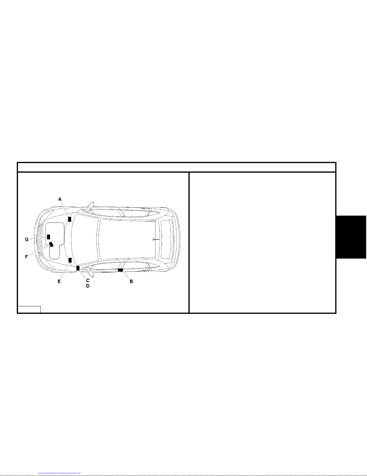
IDENTIFICATION OF VEHICLES
E1AP09HD
A: Chassis stamp
(cold stamp on bodywork).
B : Manufacturer’s data plate.
(on the LH centre pillar)
C : A-S / RP No. and RP paint code
(label on front pillar close to driver’s door).
D : Inflation pressures and tyre references.
(label on front pillar close to driver’s door)
E : Serial no. on bodywork.
F : Gearbox reference – Factory serial no.
G : Engine legislation type – Factory serial no.
GENERAL
Page 4
2
GENERAL
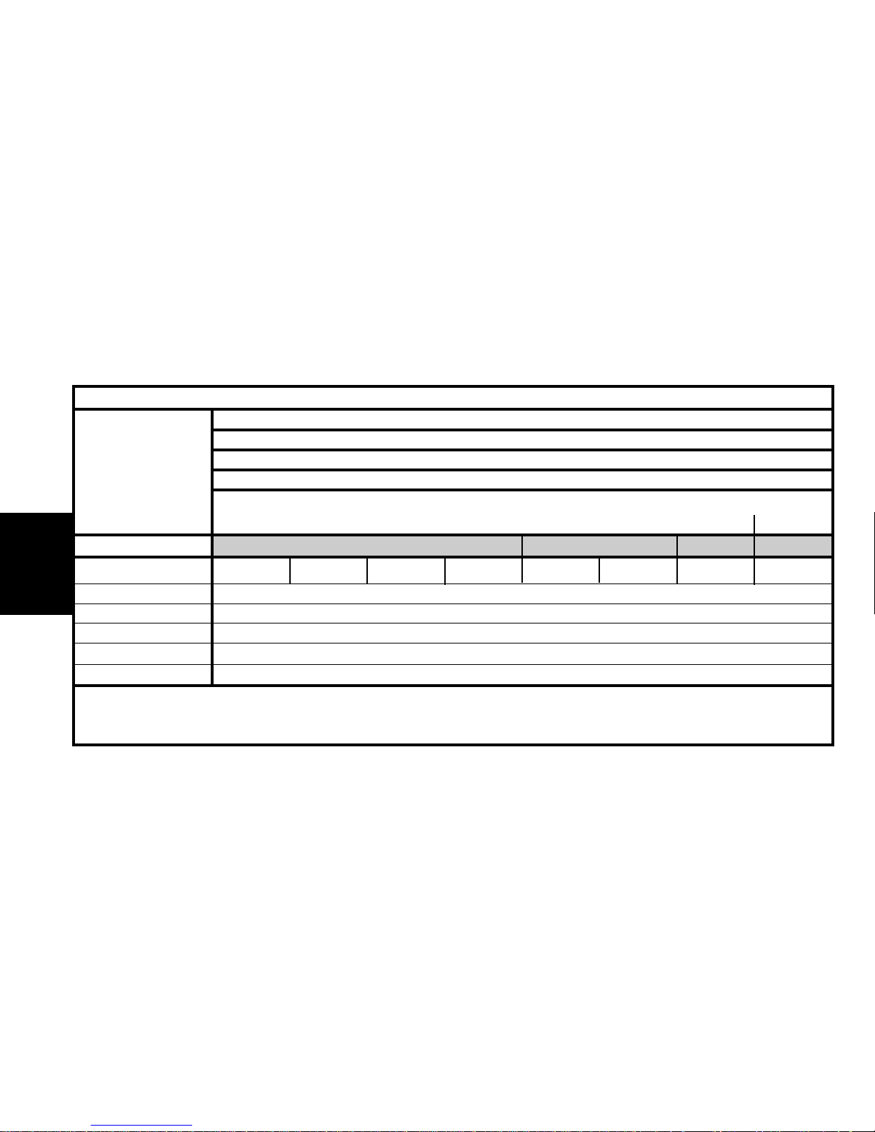
Emission standard L4 IFL5 L4/INF K’
Type code
FC HFXB/T FR HFXB FN HFXB FC HFXB
FN HFXC FC HFXC FC HFXB
FC HFX5
/IF /IF /D
Engine type HFX
Cubic capacity (cc) 1124
Fiscal rating (hp) 4
Gearbox type MA/5N
Gearbox ident. plate 20 CF 14
IDENTIFICATION OF VEHICLES
PETROL
TU
1
JP
1.1i
X-SX X
Page 5
3
GENERAL
IDENTIFICATION OF VEHICLES
(*) = Export.
PETROL
TU
3
JP
1.4i
SX – Exclusive
Auto.
Auto.
Auto.
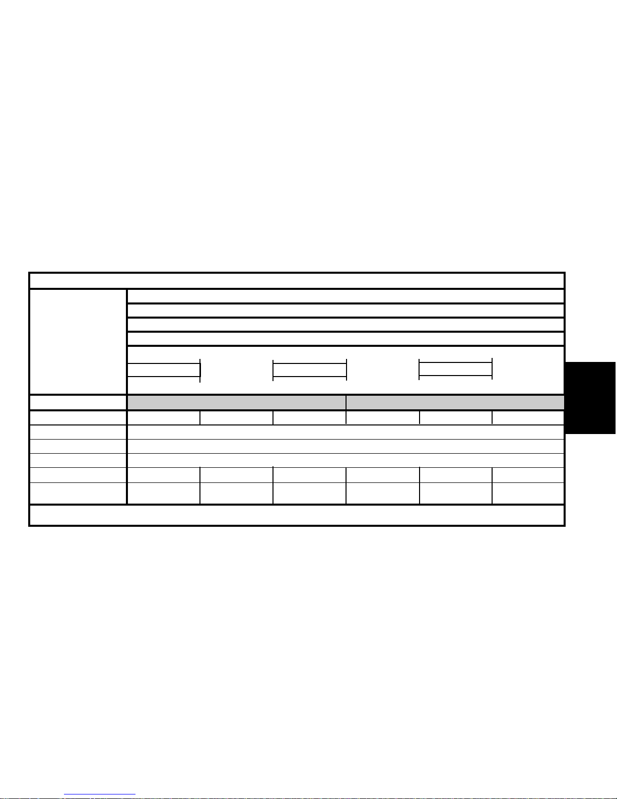
Emission standard L4 IFL5
Type code FC KFVE FN KFVB FN KFVE FC KFVC/IF FC KFVF/IF FN KFVC/IF
Engine type KFV
Cubic capacity (cc) 1360
Fiscal rating (hp) 5
Gearbox type AL4 MA/5N AL4 MA/5N AL4 MA/5N
Gearbox ident. plate 20 TP 75
20 CF 15
20 TP 75
20 CF 15
20 TP 75
20 CF 15
20 CF 16 (*) 20 CF 16 (*) 20 CF 16 (*)
Page 6
4
GENERAL
IDENTIFICATION OF VEHICLES
(*) = Export.
PETROL
TU
35
JP4
1.6i 16V
JP
1.4i
SX – Exclusive
Auto.
Emission standard IFL5 L4 L4/INF L4
Type code FN KFVF/IF FC KFVB FC KFVB/D FC KFVE/D FN NFUB FC NFUB
Engine type KFV NFU
Cubic capacity (cc) 1360 1587
Fiscal rating (hp) 56
Gearbox type AL4 MA/5N MA/5S
Gearbox ident. plate 20 TP 75 20 CF 15 20 CF 16 (*) 20 CN 40
Page 7
5
GENERAL
(*) = Export.
IDENTIFICATION OF VEHICLES
DIESEL
DV
4
TD
1.4 HDi
X - SX
Emission standard L4
Type code FC 8HBXB/T FN 8HXB FC 8HXB FC 8HXB/MOD FC 8HXK FR 8HXB
Engine type 8HX
Cubic capacity (cc) 1398
Fiscal rating (hp) 4
Gearbox type MA/5O
Gearbox ident. plate 20 CN 33 20 CN 36 (*)
Page 8
6
GENERAL
Emission standard L4
Type code FN 8HWK FC 8HWB FN 8HVB FC 8HVB
Engine type 8HW 8HV
Cubic capacity (cc) 1398
Fiscal rating (hp) 45
Gearbox type MA/50 BE4/5
Gearbox ident. plate 20 CN 33 20 CN 36 (*) 20 DM 25 20 DM 26
IDENTIFICATION OF VEHICLES
DIESEL
DV
4
TD
1.4 HDi 1.4 HDi 16V
S - SX SX - Exclusive
TED4
(*) = Export.
Page 9
7
GENERAL
IDENTIFICATION OF VEHICLES
DIESEL
DV
4
TED4
1.4 HDi 16V
SX - Exclusive SX SX - Exclusive
Emission standard L4
Type code FN 8HYB FC 8HYC FC 8HYB/MOD FC 8HYB/T FC 8HYK FR 8HYB
Engine type 8HY
Cubic capacity (cc) 1398
Fiscal rating (hp) 5
Gearbox type BE4/5
Gearbox ident. plate 20 DM 25 20 DM 26
Page 10
8
GENERAL
IDENTIFICATION OF VEHICLES
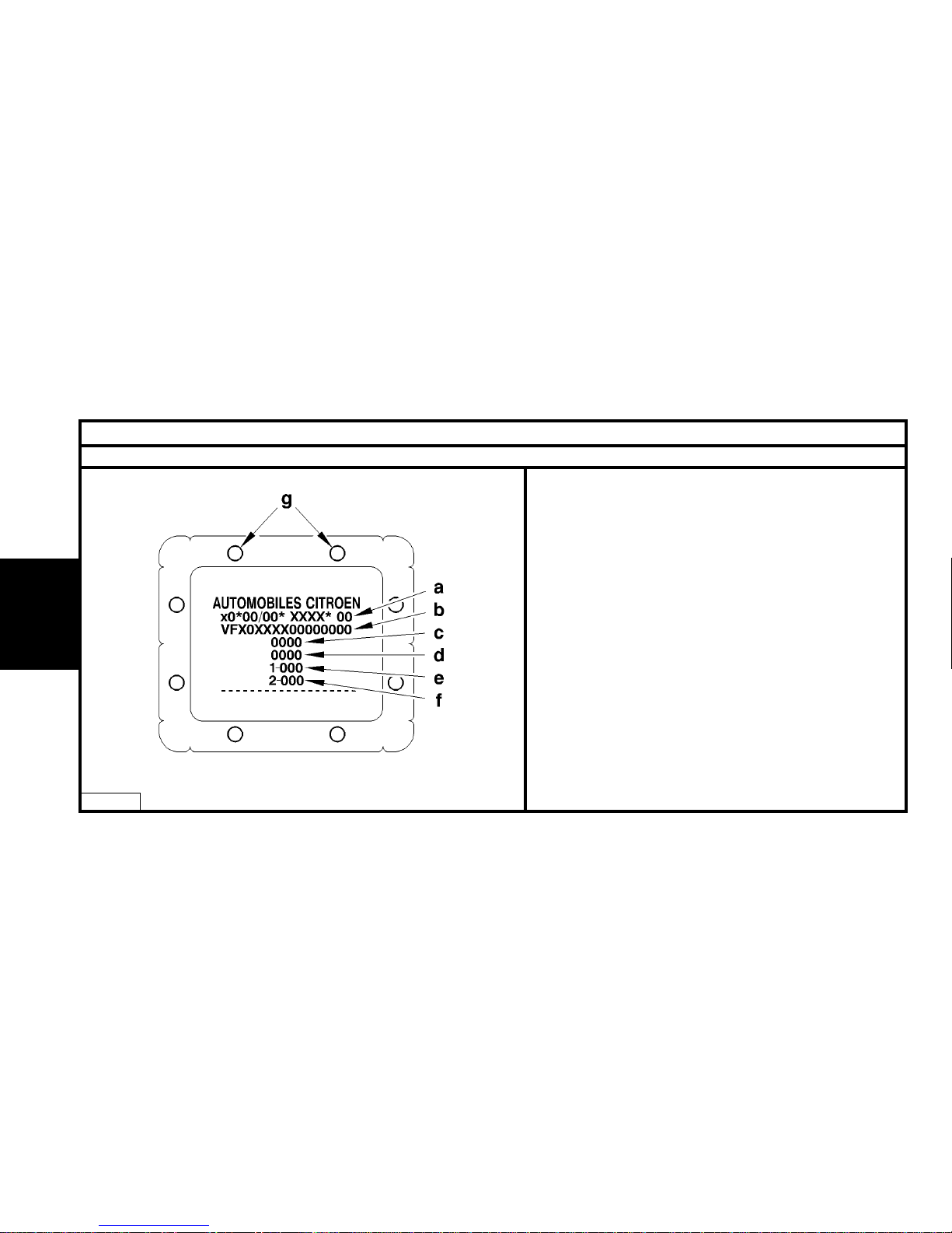
Manufacturer’s plate.
E1AP09JC
The manufacturer’s plate carries the following information :
(a) Type approval number (*).
(b) Type serial number.
(c) Gross vehicle weight (*).
(d) Gross vehicle weight (*).
(e) Maximum weight on front axle (*).
(f) Maximum weight on rear axle (*).
(g) Manufacturer identification.
(*) = According to marketing country.
Page 11
9
GENERAL
IDENTIFICATION OF VEHICLES
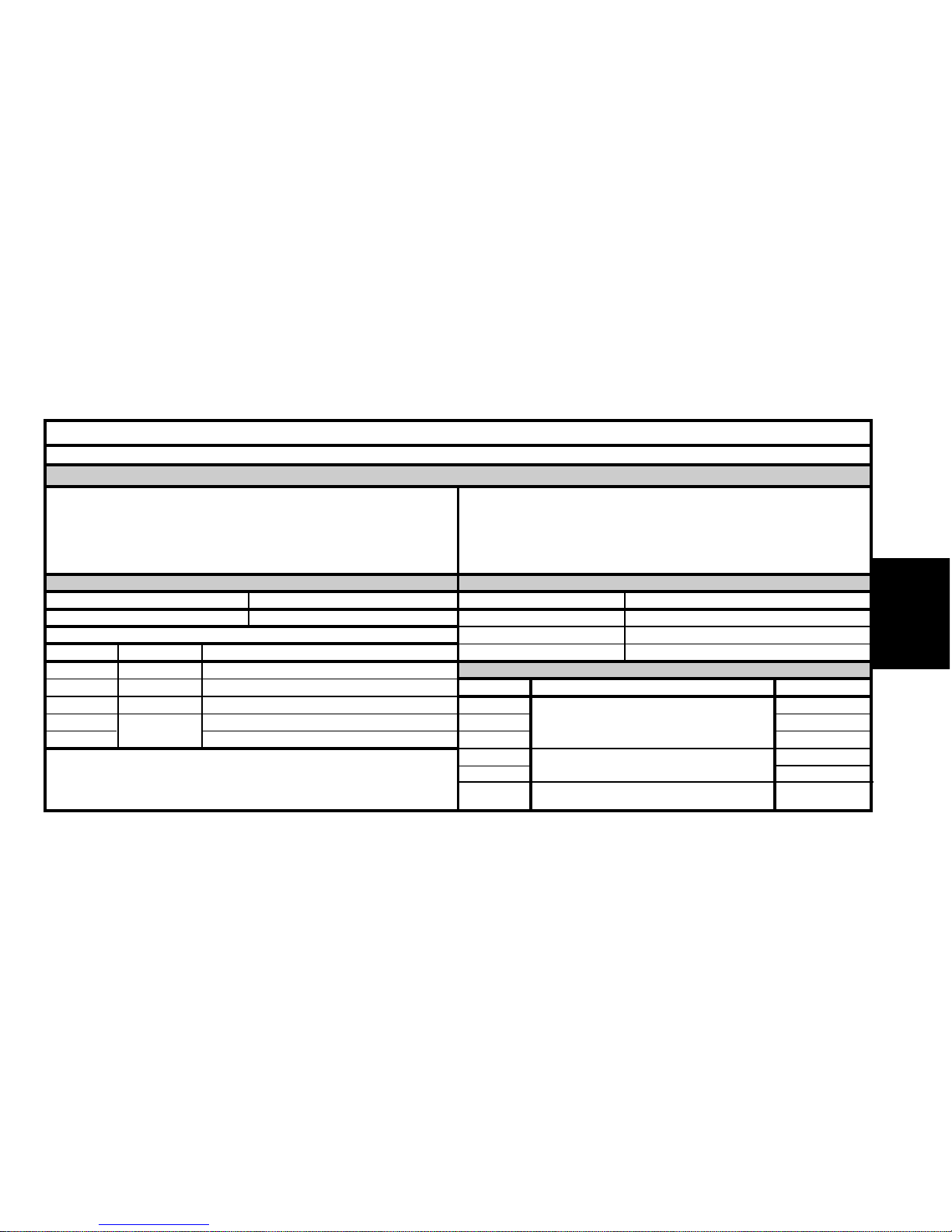
Factory code.
Structure
The factory code is composed of 6 figures or letters.
F = Vehicle family.
C = Body shape.
8.H.Y = Engine.
B = Version.
Body shape
Ref. Body shape
5 door saloon
5 door saloon (4 seats)
5 door saloon (Van not suitable for conversion)
C
N
R
Version (Gearbox and emission standard)
Ref. Gearbox
Manual 5 gears
Automatic 4 gears
Gear ratios and/or gearbox different
from base version.
Emissions
L4
Ifl5
K’
L4
IFL4
L4
C
B
5
E
F
K
Example : F.C.8.H.Y.B :
Family
Ref.
F
Engine
Ref.
HFX
KFV
NFU
8HX-8HW
8HY-8HV
Capacity
1124
1360
1587
1398
Engine type
TU1JP/L4/IFL5/L4 INF/K’
TU3JP/L4/IFL5/L4 INF
TU5JP4/L4
DV4TD/L4
DV4TED4/L4
Family
CITROËN C3
Page 12
10
GENERAL
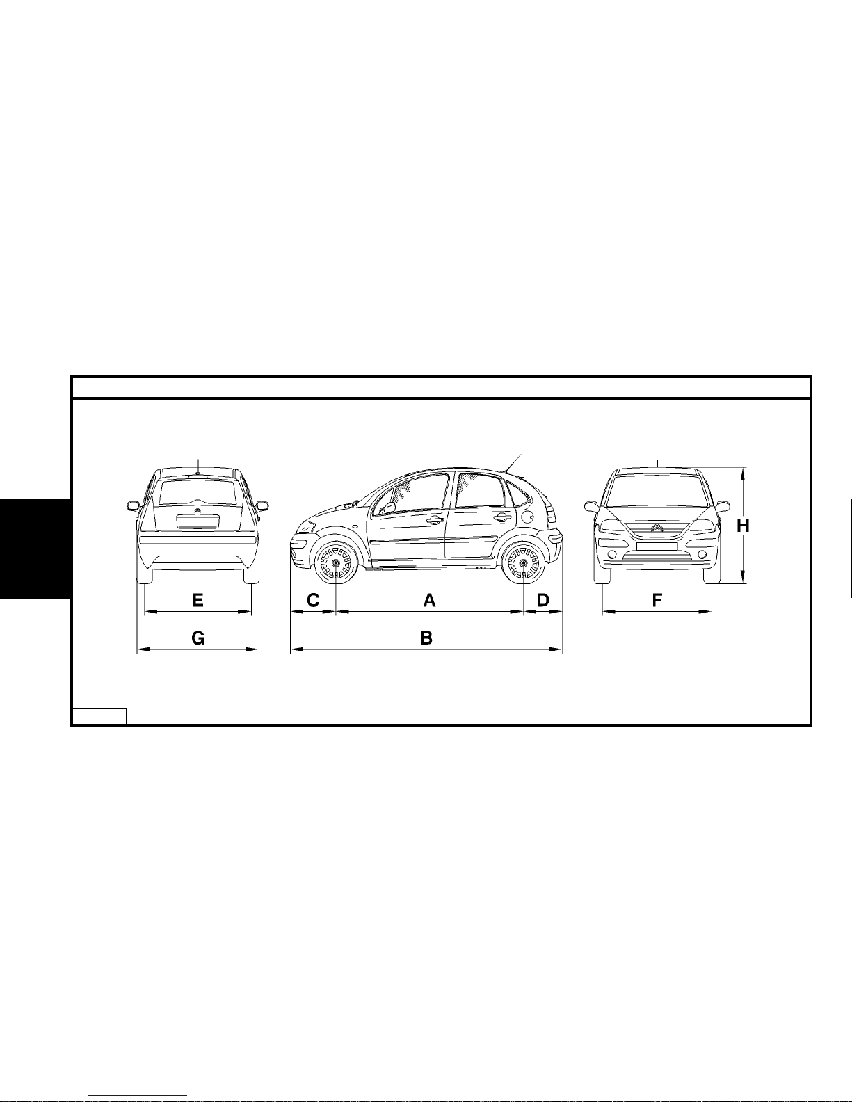
GENERAL SPECIFICATION : DIMENSIONS
E1AP09KD
Page 13
Exterior dimensions (mm)
11
GENERAL
GENERAL SPECIFICATION : DIMENSIONS
Interior dimensions and volumes (mm)
Vehicles All types
Wheelbase A 2460
Length overall B 3850
Front overhang C 750
Rear overhang D 640
Rear track on the ground E 1435
Front track on the ground F 1438
Width overall G 1667
Height overall (*) H 1521
ODM = Vehicle in running order (vehicle empty, levels topped up).
(*) = Boot floor with adjustable configuration.
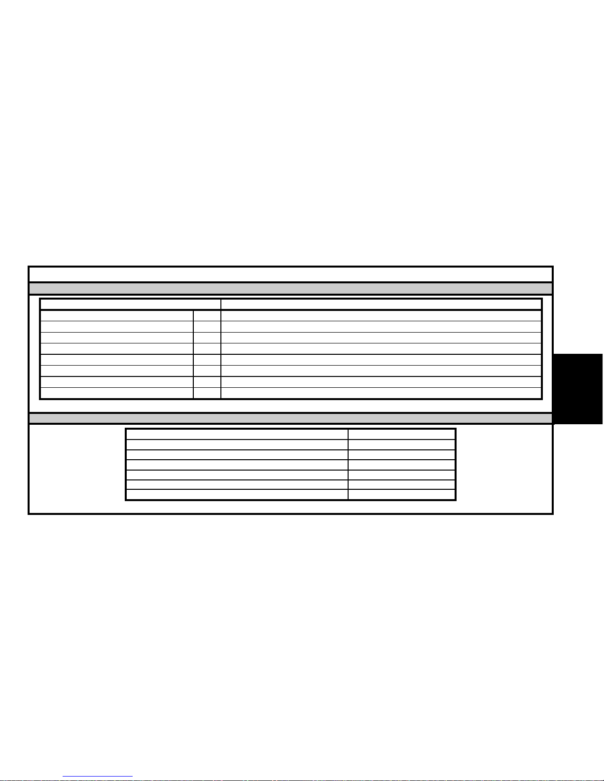
Elbow width, front 1406
Elbow width, rear 1402
Height of boot below parcel shelf 585
Minimum floor width 1040
Length of bootspace at floor level 660
Volume of boot below parcel shelf (dm
3
) 305
Volume in dm3of boot below Moduboard (*) 282
Page 14
12
GENERAL
Manual Auto. Manual
Versions 1.1i 1 4i 1.6i 1.4i 1.4 HDi 1.4 HDi 16V
Engine type HFX KFV NFU KFV 8HX 8HW 8HY 8HV
Gearbox type MA/5N AL4 MA/50 BE4/5
Payload 485 465 467 468 479 467
Weight empty in Without options 1053 1080 1133 1114 1097 1147
running order With all options 1138 1147 1200 1182 1177 1214
Gross vehicle weight 1463 1470 1525 1507 1501 1539
Gross train weight 2113 2370 2425 2407 2401 2439
Maximum trailer weight without brakes 526 540 566 557 548 573
Maximum trailer weight with brakes
Incline 12% 926 1174 1176 1175 1176
Maximum nose weight 38 47 48 47 48
Maximum roof rack load 60 kg
GENERAL SPECIFICATION : WEIGHTS
Petrol Diesel
Page 15
13
GENERAL
OPERATIONS TO BE CARRIED OUT AFTER A REPAIR
IMPERATIVE : All these operations are to be performed following a reconnection of the battery.
Antiscanning function.
It is necessary to wait 1 minute after the battery has been disconnected in order to be able to start the vehicle.
Tailgate.
The opening of the tailgate is deactivated on reconnection of the battery.
Perform locking/unlocking to activate the opening of the tailgate.
Overspeed check.
The vehicle’s overspeed values have to be re-initialised.
The button on the wiper stalk operates the following functions:
- Activation of the vehicle’s overspeed function.
- Programming of the overspeed alert.
Electric windows
It is necessary to re-initialise the sequential and anti-pinch function
NOTE : If the window is open at the time the battery is reconnected, action the window switch several times to close it, then re-initialise.
Open the window fully.
Action and release the window switch until the window is completely closed.
This operation has to be carried out on each electric window.
Page 16
14
GENERAL
OPERATIONS TO BE CARRIED OUT AFTER A REPAIR
Sun roof.
The anti-pinch function has to be re-initialised.
Place the sun roof switch in the maximum tilt position.
Keep the sun roof switch pressed until the sun roof ceases its movement.
Release the sun roof switch within 5 seconds.
Keep the sun roof switch pressed until the end of the sun roof opening sequence.
Multifunction screen.
It is necessary to adjust the date, time and outside temperature.
Adjust the display language of the multifunction screen if necessary.
NOTE : The default display language of the multifunction screen is French.
Navigation.
Vehicle location is only effective after some ten minutes.
Reprogramme the customer parameters.
Radio.
Reprogramme the radio stations.
Page 17
15
GENERAL
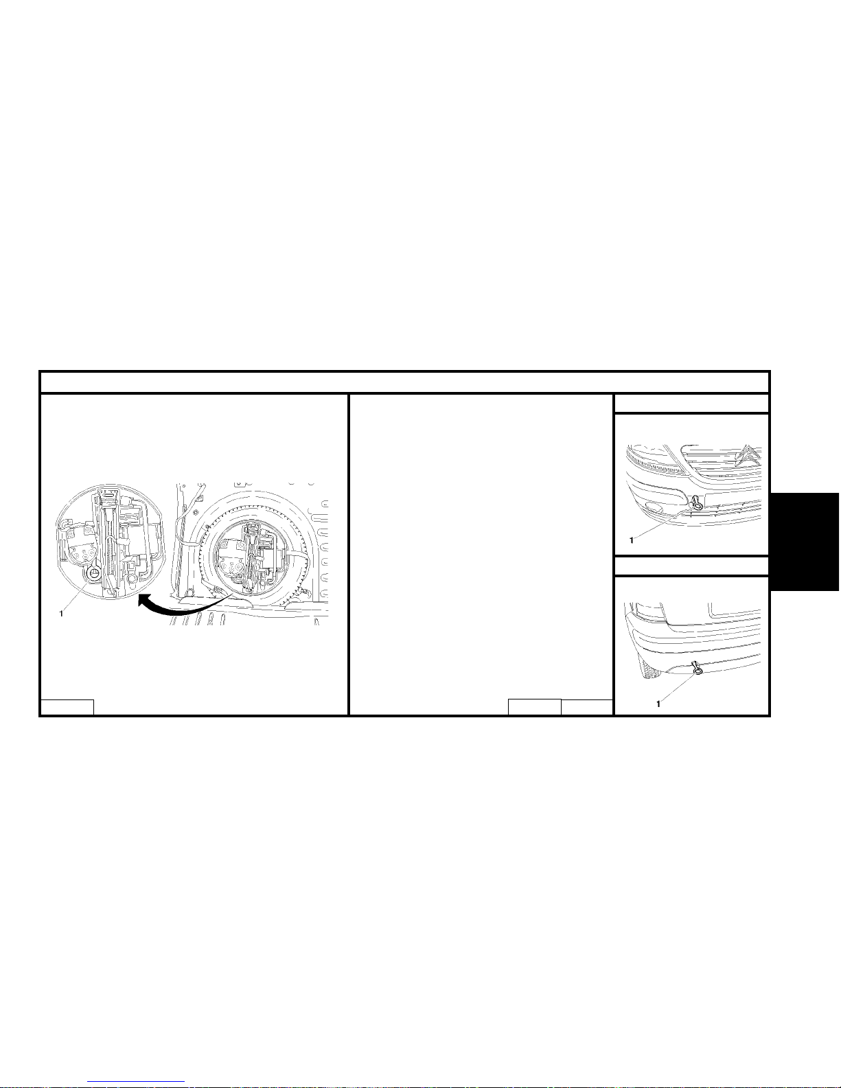
GENERAL SPECIFICATION : TOWING THE VEHICLE
Front towing
Rear towing
WARNING : When the engine is not running,
steering and braking are no longer powerassisted.
Towing eye
(1) Towing eye
The towing eye is stowed in the jack protection box inside the spare wheel.
E2AP01KD
E2AP01LC
E2AP01MC
Page 18
16
GENERAL
GENERAL SPECIFICATION : TOWING THE VEHICLE
Vehicle towing : Precautions to be taken
Manual gearbox AL4 automatic gearbox
ESSENTIAL : Never tow the vehicles with wheels hanging
(towing by the wheels).
ESSENTIAL : Never tow the vehicles with wheels hanging
(towing by the wheels).
AL4 autoactive gearbox.
Towing.
In the event of impossibility to raise the front of the vehicle :
- It is ESSENTIAL to place the selection lever in position «N».
- Do not add oil.
- Do not exceed a speed of 30 mph over a distance of 30 miles.
Moving the vehicle.
- Never be towed with the ignition switched off.
- Never attempt to push-start the vehicle.
NOTE : The automatic gearbox is only lubricated when the engine
is running.
Page 19
17
GENERAL
Lifting and supporting the vehicle Side liftingFront lifting
Front of the vehicle.
The authorised lifting points at the front of the vehicle are on the rear fixing bolts
of the subframe at «a».
For front lifting, take weight at the two lifting points at «a», using a crossbeam
equipped with blocks.
For front lifting from the side, take weight at the lifting point at «a».
ESSENTIAL :
- Never attempt to lift by the front panel mounting.
Side lifting
ESSENTIAL :
- Always ensure the jack is correctly
positioned at the lifting points.
- Do not place the axle stands under
the jack contact lugs.
Position of the axle stand.
B3CP07KC E2AP016C E2AP00GCE2AP018CE2AP017C
GENERAL SPECIFICATION: LIFTING AND SUPPORTING THE VEHICLE
Page 20
18
GENERAL
GENERAL SPECIFICATION: LIFTING AND SUPPORTING THE VEHICLE
Lifting and supporting the vehicle (continued)
Lifting with the handle jack at the front
Lifting with the handle jack at the rear
Lifting on a two-column lift using the jack supports
Lift accessory with blocks on the jack supports
E2AP01PC
E2AP01RD
E2AP01NC E2AP01QD
NOTE : The handle jack is specific to the vehicle, do not
use it for any other purposes.
Page 21
19
GENERAL
CAPACITIES (in litres)
Draining method.
Oil capacities are defined as below.
1/ Vehicle on horizontal ground (in the high position, if hydropneumatic suspension).
2/ Engine warm (oil temperature 80°C).
3/ Drain oil sump + remove filter cartidge (time for draining to last drops = 15 minutes).
4/ Refit drain plug + filter cartridge.
5/ Refill the engine.
6/ Start the engine (to allow the cartridge to fill).
7/ Stop the engine (to allow oil to stabilise for 5 minutes).
ESSENTIAL : Systematically check the oil level using the oil dipstick.
Page 22
20
GENERAL
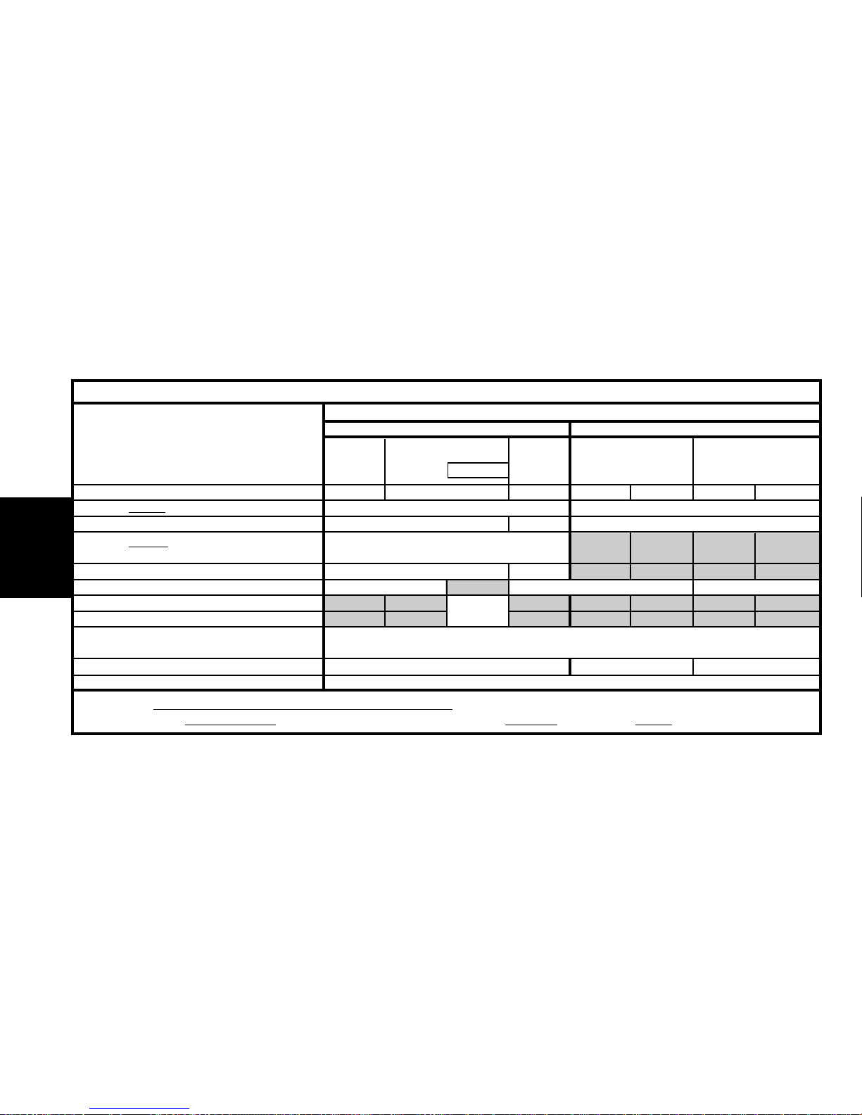
1.1i 1.4i 1.6i 16V 1.4 HDi 1.4 HDi 16V
Engine type HFX KFV NFU 8HX 8HW 8HV 8HY
Drain by gravity
: engine with filter change 2.9 3.8
Between Min. and Max. 1.5 1 2
Drain by suction
: engine
with filter change
3.1
Between Min. and Max. 1.5 1
5-speed gearbox 2 2 1.9
Automatic gearbox
(1)
After oil change
Braking circuit
0.7 Litre version with front calipers Ø 48 / rear drums
0.8 Litre version with front calipers Ø 54 / rear discs
Cooling system 7 5.7 5.6
Fuel tank capacity 45
ESSENTIAL : Systematically check the oil level using the oil dipstick.
(1) = The gearbox is lubricated for life. (For your information, the TOTALcapacity is 5.85 litres, after draining: 3 litres)
CAPACITIES (in litres)
Petrol
C3
Diesel
Auto.
Page 23
21
GENERAL
LUBRICANTS – TOTAL recommended oils
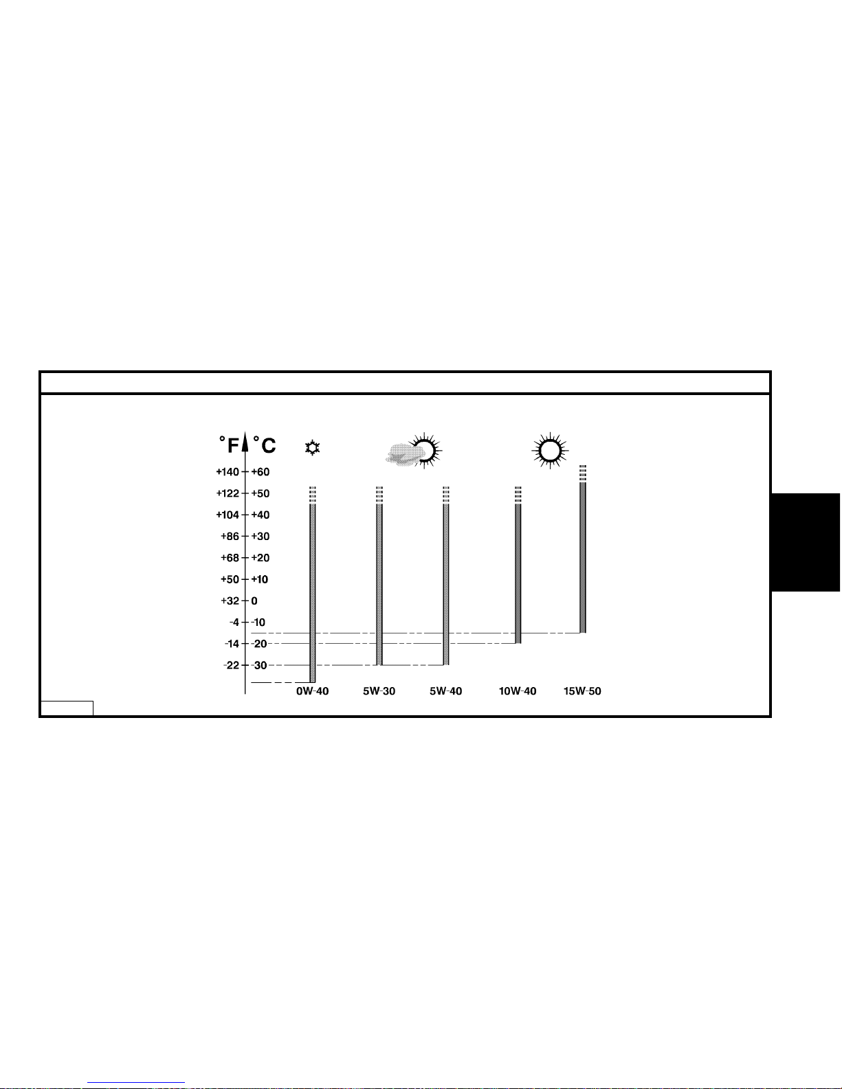
S.A.E. Norm - Table for selection of engine oil grade
E4AP006D
Page 24
LUBRICANTS – TOTAL recommended oils
22
GENERAL
Factory evolutions in 2001 model year
CITROËN engines are lubricated at the factory with TOTAL oil of
grade S.A.E.5W-30.
TOTAL oil of grade S.A.E.5W-30 allows improved fuel economies
(approx 2.5%).
Features of CITROËN C5 :
2.0 and 2.2 HDi engines have a particle filter.
The maintenance interval for normal operation
is 30.000 km (20.000 miles) for petrol engines.
WARNING : HDi engines are high technology engines which
imperatively require use of quality SYNTHETIC OILS : TOTAL
ACTIVAor TOTAL QUARTZ 5W40.
To maintain engine performances, all countries in Europe
should observe this requirement.
NOTE : Only PORTUGAL and GREECE may use 10W40 semi-
synthetic oil.
ESSENTIAL : For all vehicles with a 30.000 km (20.000 miles)
maintenance interval, use exclusively TOTALACTIVA/QUARTZ
7000 or 9000 or any other oils offering identical specifications
to these.
These oils offer specifications that are superior to those
defined by norms ACEA A3/98 or API SJ.
Failing this, it is essential to adhere to the maintenance programmes covering severe operating conditions.
5W30 cannot be used in the following engines:
XU10J4RS : XSARA VTS 2.0i 16V (3 doors).
SOFIM : RELAY 2.8 D and 2.8 TD.
1580 SPI : DISPATCH 1.6i.
2.0 and 2.2 HDi engines equipped with particle filter.
WARNING : CITROËN engines prior to model year 2000 do
not have to be lubricated with oils adhering to the norms
ACEA A1-98/B1-98 and API SJ/CF EC.
Page 25
23
GENERAL
LUBRICANTS – TOTAL recommended oils
Selection of engine oil grades recommended for climatic conditions in countries of distribution
ACEA Norms
The first letter corresponds to the type of engine concerned :
A : petrol and dual fuel petrol / LPG engines.
B : diesel engines.
The figure following the first letter corresponds to the type of oil.
1 : highly fluid oils, for reducing friction and lowering fuel
consumption.
3 : high performance oils.
The number after that (96 or 98) corresponds to the year of creation of the norm.
NOTE : From 01/03/2000, all engine oils must comply with ACEA-
98 norms.
Example :
ACEA A1-98 / B1-98 : Blended oils for all engines, permitting fuel
economy (complying with ACEA 98 norms).
API Norms
The first letter corresponds to the type of fuel used by the engine :
S : petrol and dual fuel petrol / LPG engines.
C : diesel engines.
The second letter corresponds to the degree of evolution, in ascending
order.
Example : The norm SJ is more severe than the norm SH and
corresponds to a higher level of performance.
The adding of the lettersEC indicates that the engine oil concerned is
an oil which permits fuel economy.
EC : Energy Conserving, reduction in fuel consumption.
Examples :
API SJ / CF : Blended oils for all engines.
engines API CF / EC: Oils specifically for diesel engines, permitting
fuel economy.
API SJ / CF / EC : Blended oils for all engines, permetting fuel
economy.
Page 26
24
GENERAL
LUBRICANTS – TOTAL recommended oils
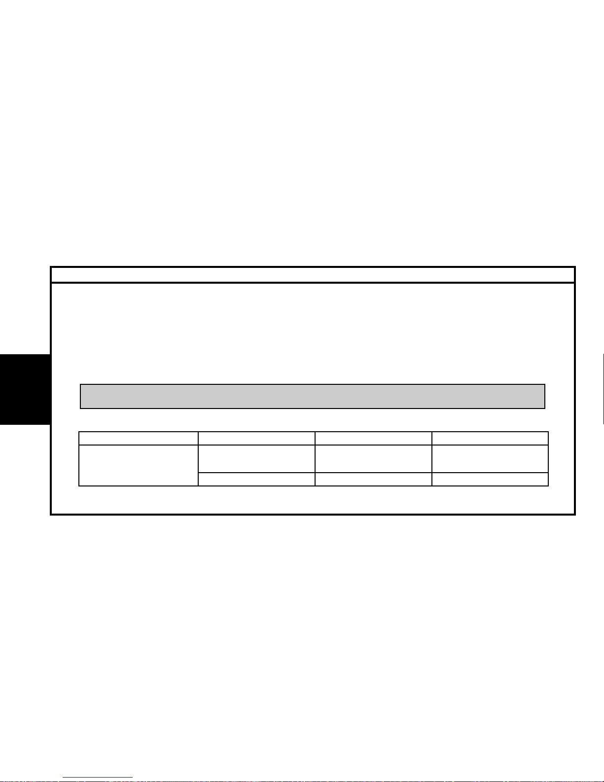
Engine oil norms.
Norms in force.
These engine oils have been classified by the following recognised organisations:
S.A.E. : Society of Automotive Engineers.
API : American Petroleum Institute.
ACEA : Association des Constructeurs Européens d’Automobiles.
Recommendations.
Denominations of TOTAL oils, according to country of marketing:
TOTAL ACTIVA (France only).
TOTAL QUARTZ (Outside France).
Summary
Engine oil norms to be respected in 2001 model year
(*) = It is essential not to use engine oils respecting these norms for the following engine-types .
XU10J4RS, 1580 SPI, SOFIM 2.8 D and SOFIM 2.8 TD.
ESSENTIAL : To preserve engine performances, all engines fitted in CITROEN vehicles must be lubricated with high
quality oils (synthetic or semi-synthetic)
Model year Types of engine ACEA norms API norms
Petrol and dual fuel petrol / A3-98 or A1-98 (*) SJ or SJ / EC (*)
AM 2001
LPG engines
Diesel engines B3-98 or B1-98 (*) CF or CF / EC (*)
Page 27
25
GENERAL
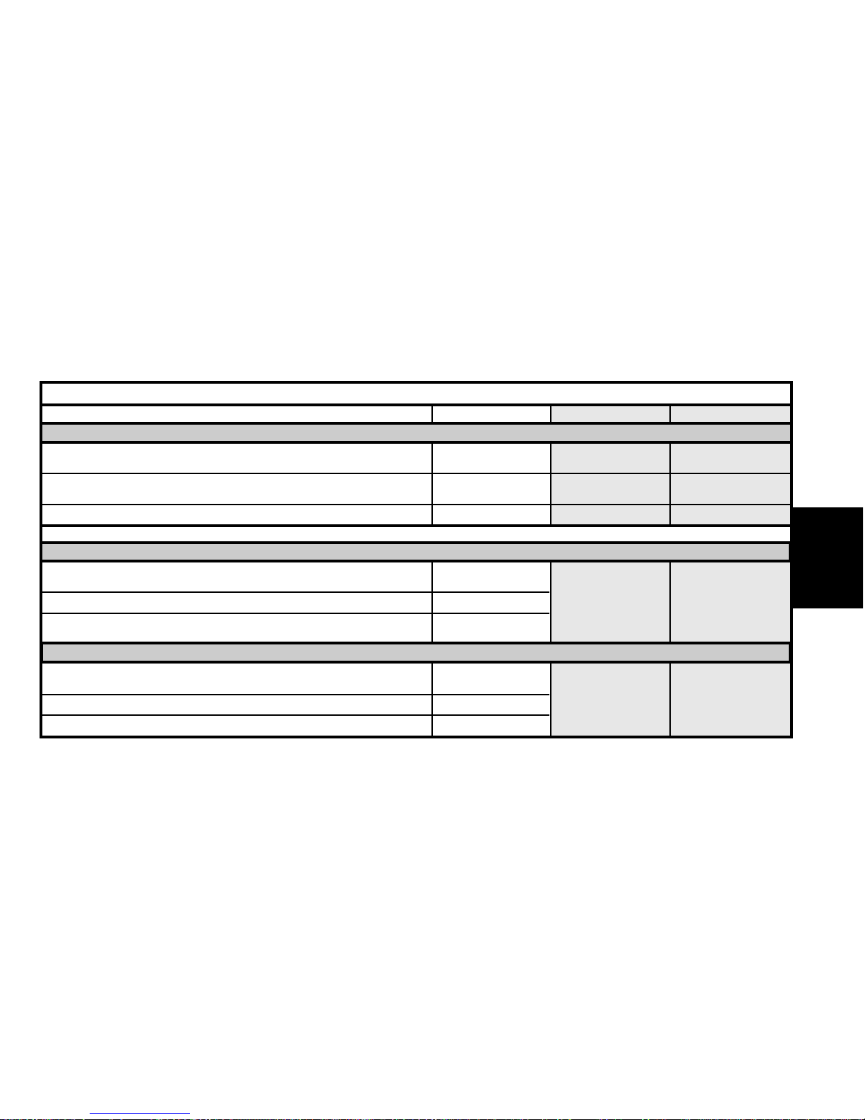
S.A.E. grades SPI norms ACEA norms
Blended oils for all engines (petrol, dual-fuel petrol / LPG and diesel)
TOTAL ACTIVA9000
TOTAL QUARTZ 9000
5W-40 SJ / CF A3-98 / B3-98
TOTAL ACTIVA9000. (*)
TOTAL QUARTZ 9000. (*)
5W-30 SJ / CF EC A1-98 / B1-98
TOTAL ACTIVRAC 10W-40 SJ / CF A3-98 / B3-98
(*) = Blended oils for all engines, permitting fuel economy.
Oils specifically for petrol and dual-fuel petrol / LPG engines
TOTAL ACTIVA7000
TOTAL QUARTZ 7000
10W-40
TOTAL QUARTZ 9000 0W-40 SJ A3-98
TOTAL ACTIVA7000
TOTAL QUARTZ 7000
15W-50
Oils specifically for diesel engines
TOTAL ACTIVADIESEL 7000
TOTAL QUARTZ DIESEL 7000
10W-40
TOTAL ACTIVADIESEL 7000
15W-50
CF B3-98
TOTAL ACTIVADIESEL 9000 5W-40
LUBRICANTS – TOTAL RECOMMENDED OILS
Page 28
26
GENERAL
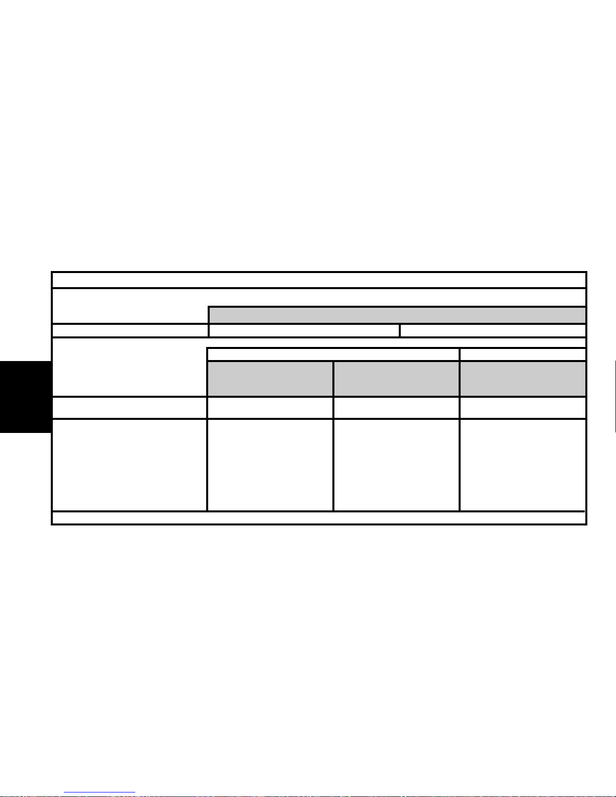
FRANCE
Metropolitan FRANCE
Metropolitan FRANCE
New Caledonia
Guadeloupe
Saint-Martin
La Réunion
Martinique 9000 5W-40 7000 15W-50 7000 15W-50
Guyana
Tahiti
Mauritius
Mayotte
LUBRICANTS – TOTAL RECOMMENDED OILS
Blended oils for all engines, supplied in bulk
TOTAL ACTIVRAC S.A.E : 10W-40 Norms
TOTAL ACTIVA
9000 5W-40
9000 5W-30 (*)
7000 10 W-40
7000 10W-40
9000 5W-40
TOTAL ACTIVA DIESEL
Blended oils for all engines
Oils specifically for petrol and
dual-fuel petrol / LPG engines
Oils specifically for diesel
engines
(*) = Blended oils for all engines, permitting fuel economy.
Page 29
27
GENERAL
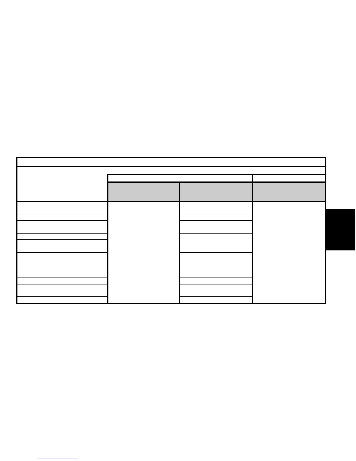
EUROPE
Germany
Austria
Belgium
Bulgaria
Cyprus
Croatia
Denmark
Spain
Estonia
Finland
Great Britain
LUBRICANTS – TOTAL RECOMMENDED OILS
TOTAL QUARTZ
TOTAL QUARTZ DIESEL
Blended oils for all engines
Oils specifically for petrol and
dual-fuel petrol / LPG engines
Oils specifically for diesel
engines
9000 5W-40
9000 5W-30 (*)
(*) = Blended oils for all engines,
permitting fuel economy
7000 10W-40
9000 0W-40
7000 10W-40
7000 10W-40
9000 0W-40
7000 10W-40
7000 15W50
7000 10W-40
7000 10W-40
9000 0W-40
7000 10W-40
7000 15W-50
7000.10W-40
7000 10W-40
9000 0W-40
7000 10W-40
7000 10W-40
Page 30
28
GENERAL
Oils specifically for diesel
engines
EUROPE (continued)
Greece
Holland
Hungary
Italy
Ireland
Iceland
Latvia
Lithuania
Macedonia
Malta
Moldova
Norway
Poland
Portugal
Slovak Republic
LUBRICANTS – TOTAL RECOMMENDED OILS
TOTAL QUARTZ TOTAL QUARTZ DIESEL
Blended oils for all engines
Oils specifically for petrol and
dual-fuel petrol / LPG engines
(*) = Blended oils for all engines,
permitting fuel economy
9000 5W-40
9000 5W-30 (*)
7000 10W-40
7000 10W-40
7000 15W-50
7000 10W-40
9000 0W-40
7000 10W-40
7000 10W-40
9000 0W-40
7000 10W-40
7000 10W-40
7000 15W-50
7000 10W-40
7000 10W-40
9000 0W-40
7000 10W-40
Page 31
29
GENERAL
EUROPE (continued)
Czech Republic
7000 10W-40
9000 0W-40
Romania
7000 10W-40
7000 15W-50
Russia
7000 10W-40
9000 0W-40
Slovenia 7000 10W-40
Sweden
7000 10W-40
9000 0W-40
Switzerland 7000 10W-40
7000 10W-40
Turkey 7000 15W-50
9000 0W-40
Ukraine
7000 10W-40
9000 0W-40
Yugoslavia 7000.10W-40
LUBRICANTS – TOTAL RECOMMENDED OILS
Oils specifically for diesel
engines
TOTAL QUARTZ
TOTAL QUARTZ DIESEL
Blended oils for all engines
Oils specifically for petrol and
dual-fuel petrol / LPG engines
(*) = Blended oils for all engines, per-
mitting fuel economy
9000 5W-40
9000 5W-30 (*)
7000 10W-40
Page 32
30
GENERAL
Oils specifically for diesel
engines
Australia
New-Zealand
Ivory Coast
Egypt
Gabon
Madagascar
Morocco
Senegal
Tunisia
Argentina
Brazil, Chile
Cuba
Mexico
Paraguay
Uruguay
LUBRICANTS – TOTAL RECOMMENDED OILS
TOTAL QUARTZ
TOTAL QUARTZ DIESEL
Blended oils for all
engines
Oils specifically for petrol and
dual-fuel petrol / LPG engines
OCEANIA
AFRICA
CENTRAL
AND SOUTH
AMERICA
9000 5W-40
7000 10W-40
7000 15W-50
7000 10W-40
Page 33
31
GENERAL
Oils specifically for diesel
engines
China
South Korea
Hong-Kong
India
Indonesia
Japan
Malaysia
Pakistan
Philippines
Singapore
Taiwan
Thailand
Vietnam
LUBRICANTS – TOTAL RECOMMENDED OILS
TOTAL QUARTZ
TOTAL QUARTZ DIESEL
Blended oils for all
engines
Oils specifically for petrol and
dual-fuel petrol / LPG engines
SOUTH EAST
ASIA
9000 5W-40
9000 5W-40
9000 5W-30
9000 5W-40
7000 10W-40
7000 15W-50
7000 10W-40
7000 15W-50
7000 10W-40
7000 15W-50
7000 15W-50
7000 10W-40
7000 15W-50
7000 15W-50
7000 10W-40
(*) = Blended oils for all engines, permitting
fuel economy
Page 34
32
GENERAL
Oils specifically for diesel
engines
LUBRICANTS – TOTAL RECOMMENDED OILS
TOTAL QUARTZ
TOTAL QUARTZ DIESEL
Blended oils for all engines
Oils specifically for petrol and
dual-fuel petrol / LPG engines
MIDDLE
EAST
9000 5W-40 7000 15W-50 7000 10W-50
Saudi Arabia
Bahrain
Dubai
United Arab Emirates
Iran
Israel
Jordan
Kuwait
Lebanon
Oman
Qatar
Yemen
Page 35
33
GENERAL
Manual gearbox
TOTAL TRANSMISSION BV
Norms S.A.E 75W-80
Special oil distributed by CITROËN
(Part No. 9730 A2)
MB3 automatic gearbox
All countries
TOTAL FLUIDE ATX or
TOTAL FLUIDE AT 42.
Special oils distributed by CITROËN
(Part No. 9730 A3).
4 HP 20 and AL4 automatic gearboxes
Special oil distributed by CITROËN
(Part No. 9736 22).
Transfer box and rear axle TOTAL TRANSMISSION X 4
All countries TOTAL FLUIDE ATX
Power- assisted steering TOTAL FLUIDE DA
Very cold countries Special oil distributed by CITROËN
(Part No. 9730 A1)
LUBRICANTS – TOTAL RECOMMENDED OILS
Gearbox oils
Power steering oils
Page 36
34
GENERAL
Synthetic brake fluid
LUBRICANTS – TOTAL RECOMMENDED OILS
Packs
CITROEN reference
GLYSANTIN G 33 REVCOGEL 2000
CITROEN Fluid 2 litres 9979 70 9979 72
All countries
Protection : - 35°C 5 litres 9979 71 9979 73
20 litres 9979 76 9979 74
210 litres 9979 77 9979 75
Synthetic brake fluid
Packs CITROEN reference
All countries
CITROEN Fluid
0.5 litre 9979 05
1 litre 9979 06
5 litres 9979 07
CITROEN hydraulic circuit fluid
Norm Pack CITROEN reference
TOTAL LHM PLUS
ISO 7308-7309 ZCP 830 095
Green in colour 1 litre 9979.20 (Scandinavia)
All countries
TOTAL FLUIDE LDS Orange in colour 9979.69
WARNING: TOTAL LDS fluid cannot be blended with TOTAL LHM PLUS
WARNING: CITROËN C5 : Use only TOTAL FLUIDE LDS suspension fluid.
Hydraulic circuit rinsing fluid- green in colour
All countries TOTAL HYDRAURINCAGE
Page 37
35
GENERAL
Packs CITROEN reference
Concentrated : 250 ml 9980 33 ZC 9875 953 U 9980 56
All countries
Liquid ready to use: 1 litre 9980 06 ZC 9875 784 U
Liquid ready to use: 5 litres 9980 05 ZC 9885 077 U ZC 9875 279 U
Grease
Norms NLGI (1)
TOTAL MULTIS EP2 2
All countries TOTAL MULTIS COMPLEX EP2 2
TOTAL MULTIS N4128 1
TOTAL SMALL MECHANISMS
(1) NLGI = National Lubrificating Grease Institute.
Wash/wipe fluid
LUBRICANTS – TOTAL RECOMMENDED OILS
Page 38
36
ENGINE OIL CONSUMPTION
I-Oil consumption depends on :
- the engine type.
- how run-in or worn it is.
- the type of oil used.
- the driving conditions.
II - An engine can be considered RUN-IN after:
- 3.000 miles (5.000 km) for a PETROL engine.
- 6.000 miles (10.000 km) for a DIESEL engine.
III - MAXIMUM PERMISSIBLE oil consumption for a RUN-IN engine.
- 0.5 litres per 600 miles (1.000 km) for a PETROL engine.
- 1 litre per 600 miles (1.000 km) for a DIESEL engine.
DO NOT WORK BELOW THESE VALUES.
IV - OIL LEVEL : The level should NEVER be above the MAX. mark on the dipstick after changing or topping up the oil.
- This excess oil will be used up rapidly.
- It will reduce the engine output and adversely affect the operation of the air circuits and gas recycling.
GENERAL
Page 39
37
ENGINE SPECIFICATIONS
DieselPetrol
1.1i 1.4i 1.6i 16V 1.4 HDi 1.4 HDi 16V
Engine type
Cubic capacity (cc)
Bore / Stroke
Compression ratio
Power ISO or EEC KW - rpm)
Power DIN (HP - rpm)
Torque ISO or EEC (m.daN - rpm)
Torque DIN (mkg-rpm)
Max. speed (rpm)
HFX KFV NFU 8HX 8HW 8HY 8HV
1124 1360 1587 1398
72/69 75/77 78/82 73/82
10.5/1 11/1 17.9/1 18.25/1
44-5500 54-5400 80-5800 50-4000 66-4000
61-5500 75-5400 110-5800 70-4000 92-4000
9.4-3400 12-3400 14.7-4000 15-2000 20-2000
9.8-3400 12.5-3400 15.3-4000 15.6-2000 20.8-2000
ENGINE
Page 40
38
ENGINE SPECIFICATIONS
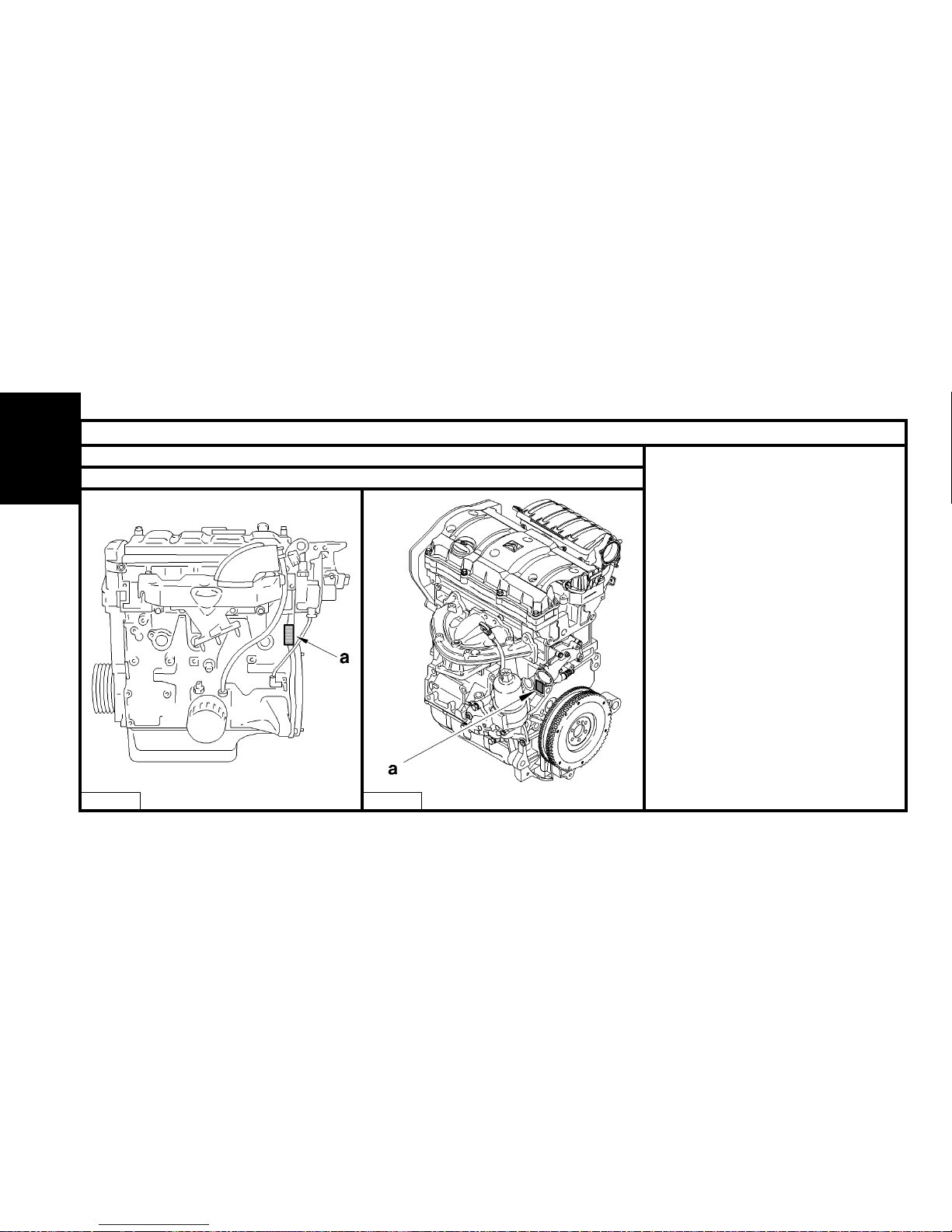
Engines : HFX - KFV - NFU
Engine identification
B1BP10JC B1BP2GKC
A=Engines: HFX - KFV
B = Engine: NFU.
Compulsory engine identification in
zone «a» :
- Component reference.
- Engine legislation type.
- Factory serial no.
ENGINE
Page 41
39
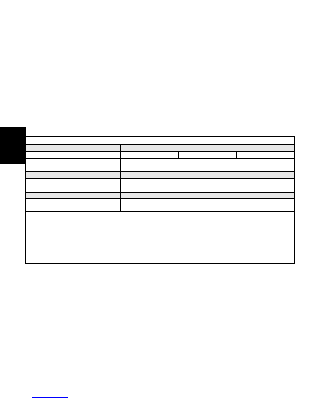
SPECIAL FEATURES : TIGHTENING TORQUES (m.daN)
Crankshaft
Engine types HFX KFV NFU
Accessories drive pulley 0.8 ± 0.2
Pinion fixing on crankshaft 10 ± 1 2.5 ± 0.2
Cylinder block
Sump 0.8 ± 0.2
Timing belt tensioner roller 2 ± 0.2 2.2 ± 0.2
Accessories belt tensioner roller 2 ± 0.2 2.5 ± 0.2
Alternator support fixing 1.7 ± 0.3
Alternator fixing on support 3.7 ± 0.3
Cylinder head
Coolant outlet housing 0.8 ± 0.2
Camshaft bearing cap
Tightening 2 ± 0.2 2 ± 0.2
Angular tightening 44°±4° 50°±5°
Inlet manifold 0.8 ± 0.2
Exhaust manifold 1.7 ± 0.3 2 ± 0.2
Valve rockers adjusting screw 1.75 ± 0.25
Sparking plugs 2.75 ± 0.25
Camshaft pulley screw 8 ± 0.8
ENGINE
Page 42
40
SPECIAL FEATURES : TIGHTENING TORQUES (m.daN)
Flywheel - Clutch
Engines HFX KFV NFU
Flywheel 6.7 ± 0.6 + LOCTITE FRENETANCH
Clutch mechanism 2 ± 0.2
Lubrication circuit
Oil pressure switch 2 ± 0.2
Oil pump 0.9 ± 0.1
Cooling circuit
Coolant pump 1.4 ± 0.1
Coolant outlet housing 0.8 ± 0.1
ENGINE
Page 43
41
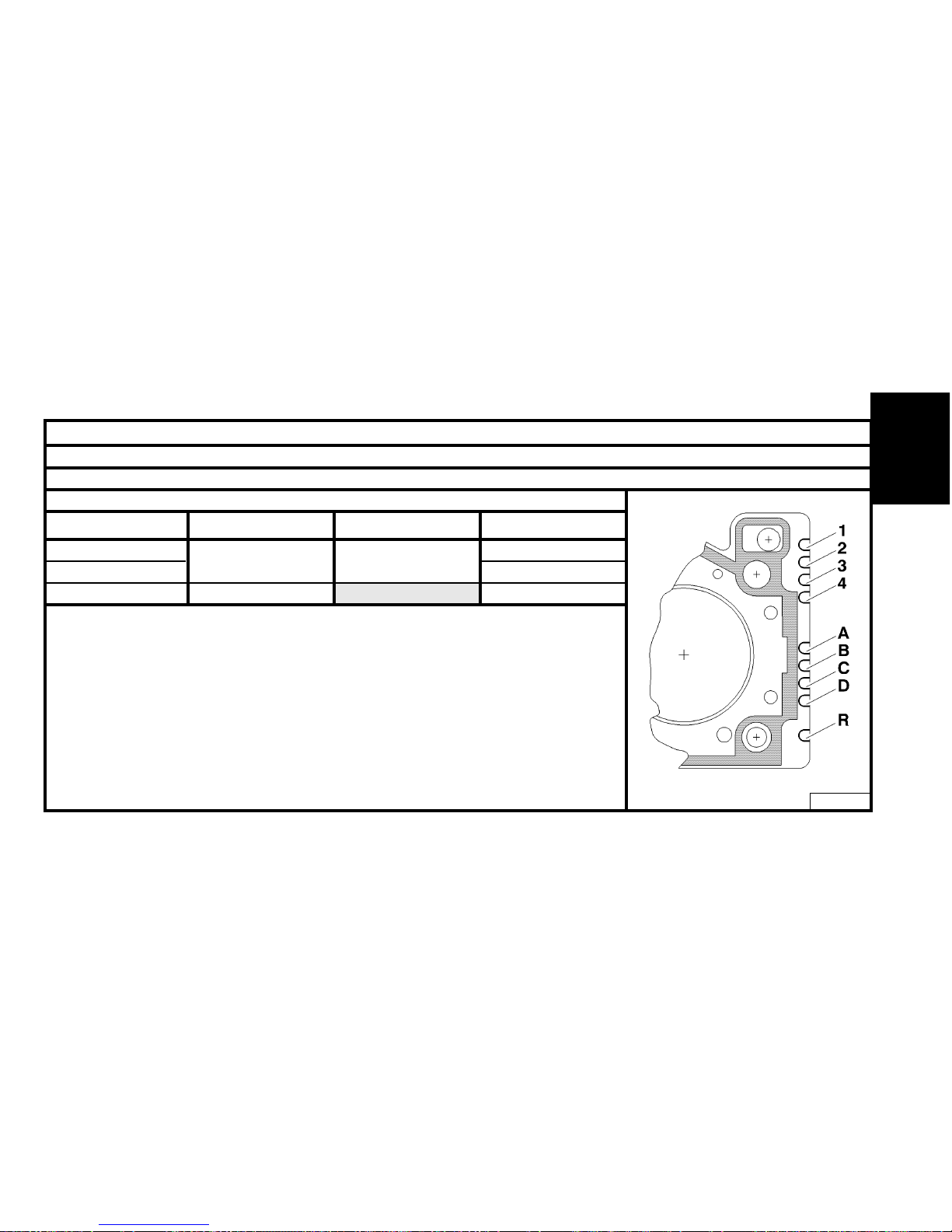
CYLINDER HEAD
Engines : HFX - KFV - NFU
Identification of cylinder head gasket
Engine types
HFX
KFV
NFU
Thicknesses (Standard)
1.2 ± 0.1
0.66 ± 0.04
Thicknesses (repair)
1.4 ± 0.1
Thickness references
2
1
4
ENGINE
References
1,2,3,4 = Type of engine.
A,B,D = Suppliers.
C = Gasket material.
R = Repair.
B1BP10KC
Page 44
42
ENGINE
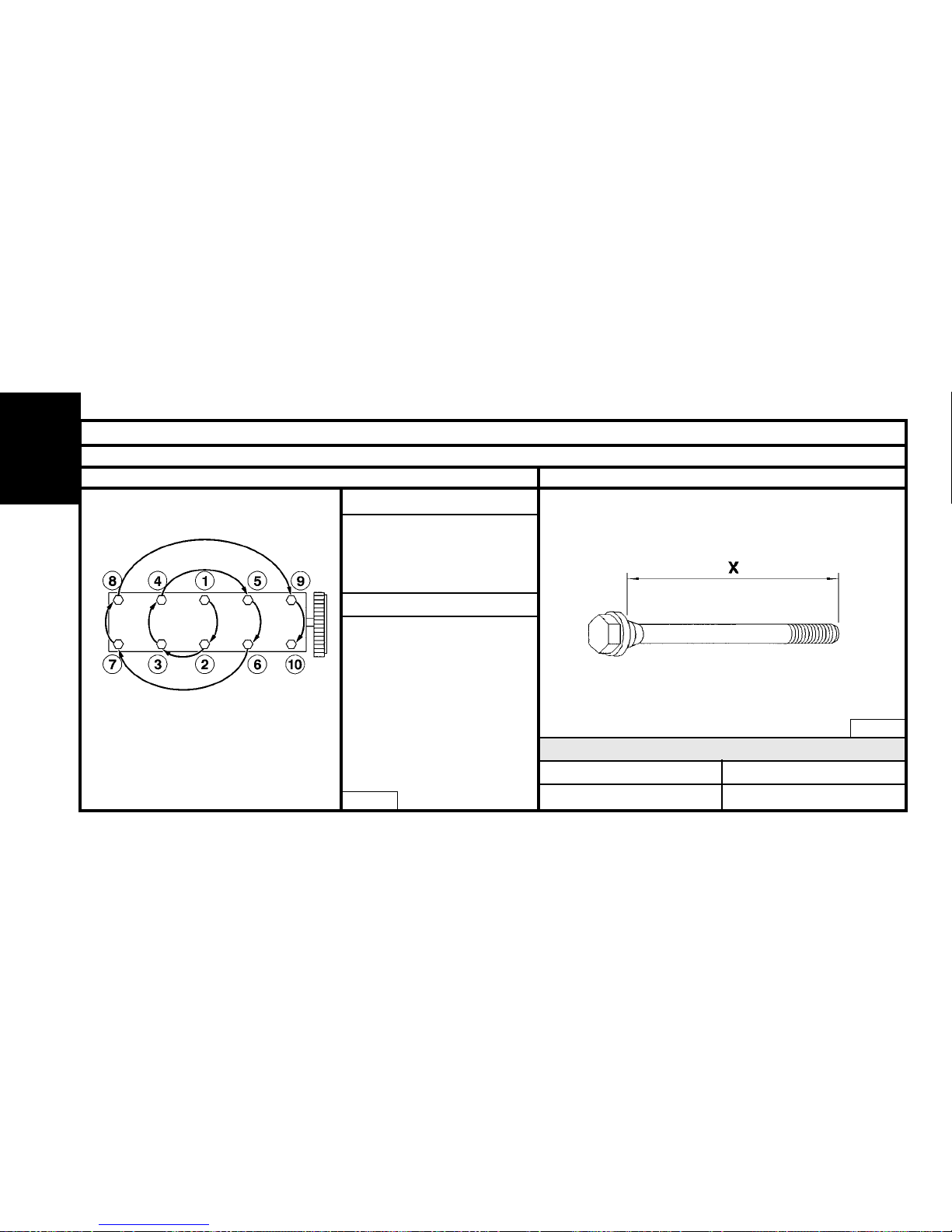
CYLINDER HEAD
Engines : HFX - KFV - NFU
Cylinder head tightening (m.daN) Cylinder head bolts
X = MAXIMUM reusable length
Tightening 2 ± 0.2
Angular tightening 240°±5°
(In the order 1 to 10)
Tightening 2 ± 0.2
Angular tightening 260° ± 5°
(In the order 1 to 10)
NOTE : Oil the threads and
under the heads of the bolts.
(Use engine oil or Molykote G
Rapid Plus).
B1BP1DVC
NFU
HFX - KFV
HFX - KFV
175.5 ± 0.5 122 ± 0.3
NFU
B1DP05BC
NOTE : Retightening of the cylinder head
after a completed repair is prohibited.
Page 45
43
ENGINE
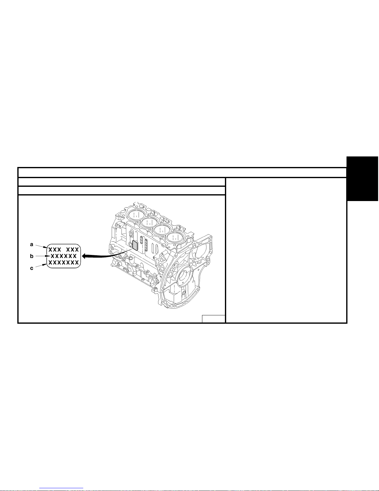
ENGINE SPECIFICATIONS
Engines : 8HX - 8HW
Engine identification
"a" Engine legislation type.
"b" Component reference.
"c" Factory serial no.
B1CP0BKD
Page 46
44
ENGINE
CYLINDER HEAD
Engines : 8HX - 8HW
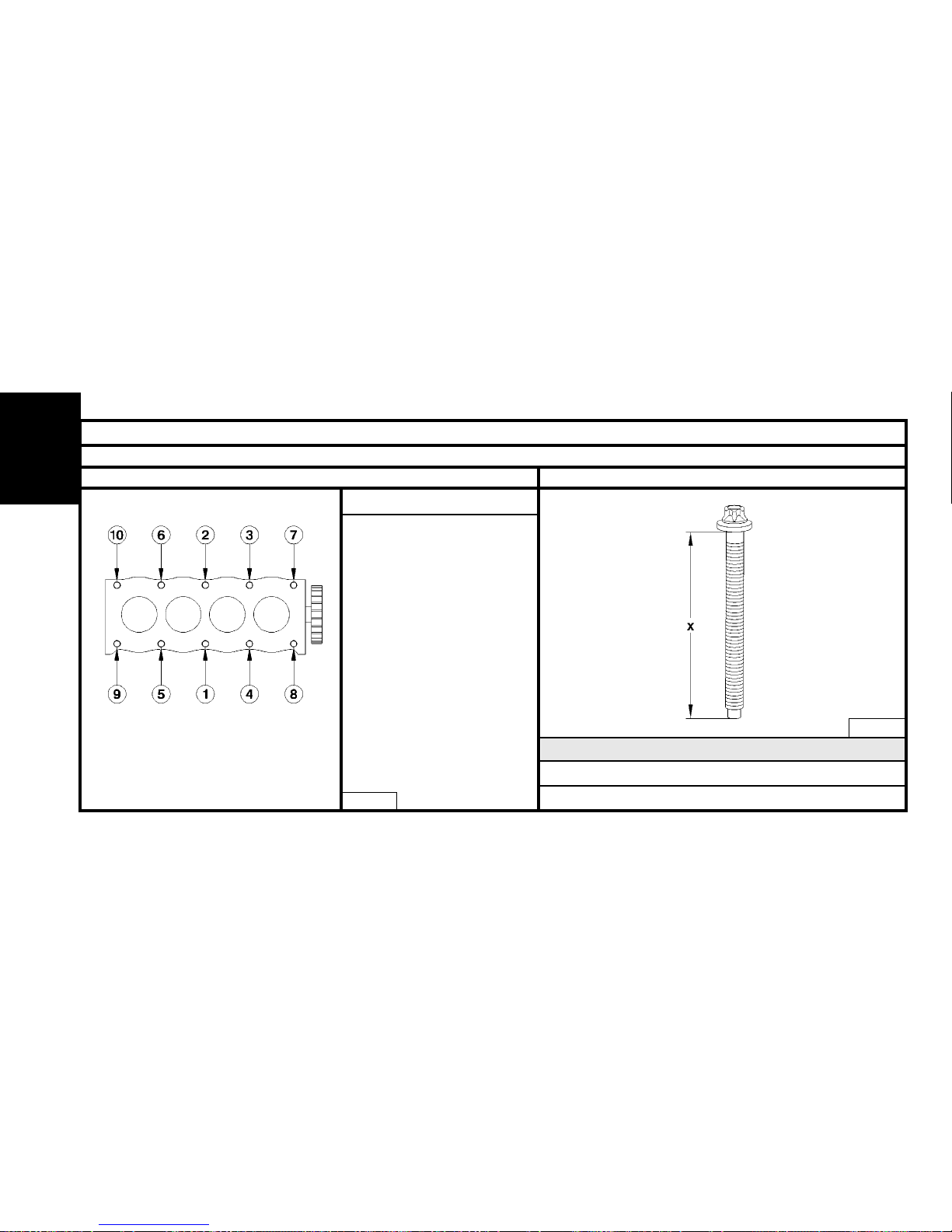
Cylinder head tightening (m.daN) Cylinder head bolts
X = MAXIMUM reusable length
Pre-tightening 2 ± 0.2 m.daN
Tightening 4 ± 0.4 m.daN
Angular tightening 230° ± 5°
(In the order 1 to 10)
NOTE :
- The bolts should have been thoroughly cleaned and dried with a
dry metal brush.
- Oil the threads and under the
heads of the bolts. (Use engine
oil or Molykote G Rapid Plus).
- Pass a tap into the holes in the
cylinder block.
8HX - 8HW
8HX - 8HW
X = 149 mm
B1DP1CLC
B1DP1DBC
NOTE : Retightening of the cylinder head
after a completed repair is prohibited.
The cylinder head gasket is dry-fitted.
Page 47
45
ENGINE SPECIFICATIONS
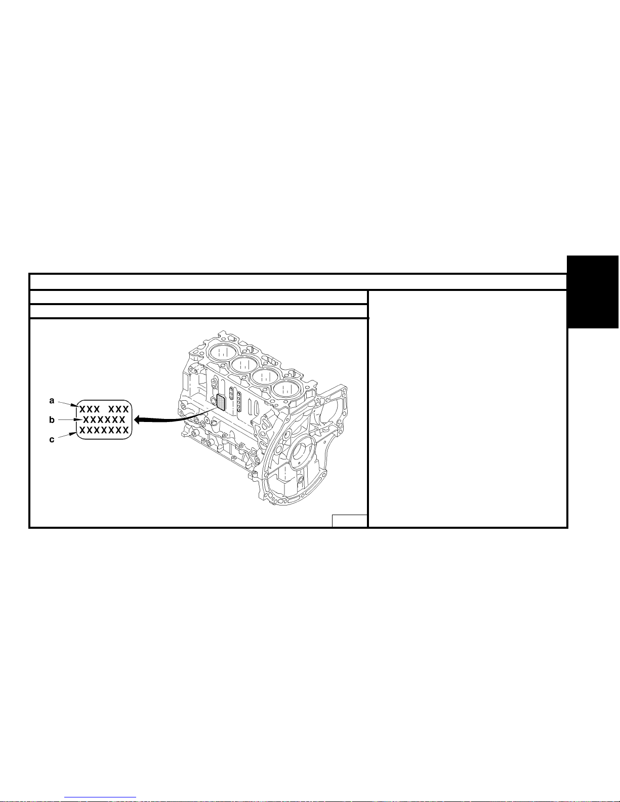
Engines : 8HY - 8HV
Engine identification
"a" Engine legislation type.
"b" Component reference.
"c" Factory serial no.
B1CP0BKD
ENGINE
Page 48
46
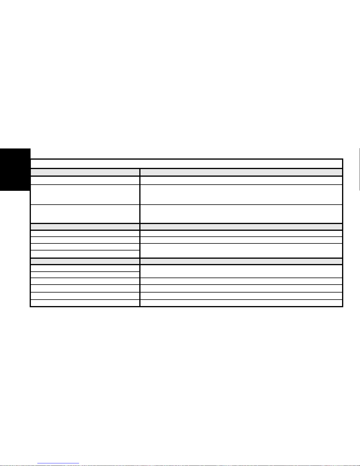
SPECIAL FEATURES : TIGHTENING TORQUES (m.daN)
Crankshaft
Engines 8HY-8HV
Bearing cap fixing screw
Tightening 3 ± 0.3
Angular tightening 140°±1°.4'
Crankshaft pullet hub
Tightening 3 ± 0.3
Angular tightening 180° ± 5°
Cylinder block
Oil sump 1 ± 0.1
Timing belt tensioner roller 4 ± 0.4
Timing belt guide roller
2.5 ± 0.2
Timing belt guide roller support
Cylinder head
Camshaft bearing cap cover
1 ± 0.1
Inlet manifold
Exhaust manifold 2.5 ± 0.2
Cylinder head cover Bolts (M6) to 1 ± 0.2
Camshaft pinion 4.3 ± 0.4
Fuel high pressure pump pinion 5 ± 0.5
ENGINE
Page 49
47
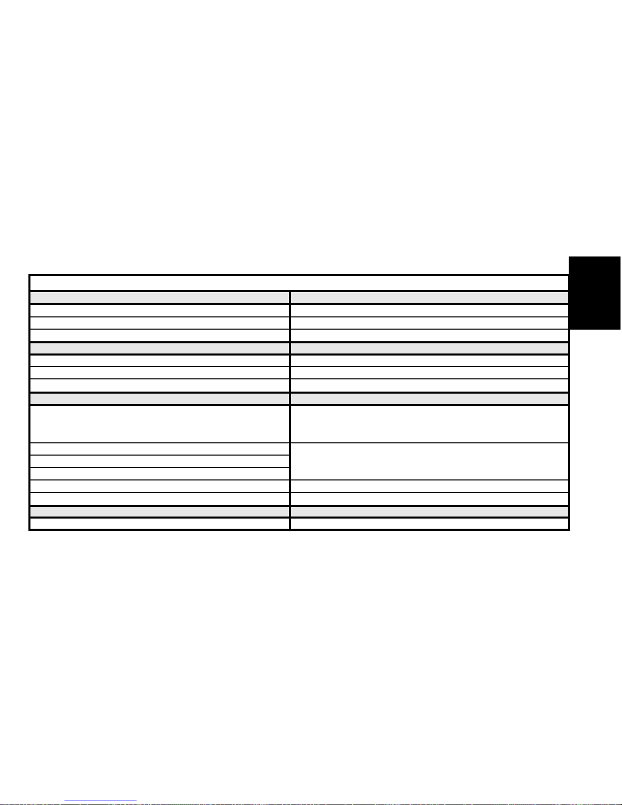
SPECIAL FEATURES : TIGHTENING TORQUES (m.daN)
Flywheel - Clutch
Engines 8HY-8HV
Flywheel 1.7 ± 0.2
Clutch mechanism 2 ± 0.2
Lubrication circuit
Oil pump assembly 0.9 ± 0.1
Oil/coolant heat exchanger 1 ± 0.1
Turbocharger lubrication pipe 2.2 ± 0.2
Injection circuit
Injector fixing flange nut
Tightening 0.4 ± 0.1
Angular tightening 65°±5°
Unions on fuel high pressure common injection rail
2.3 ± 0.2
Fuel high pressure pump
Union on diesel injector
Fuel high pressure pump pinion 5 ± 0.5
Union on fuel high pressure pump 2.3 ± 0.2
Cooling circuit
Coolant pump 1 ± 0.2±
ENGINE
Page 50
48
ENGINE
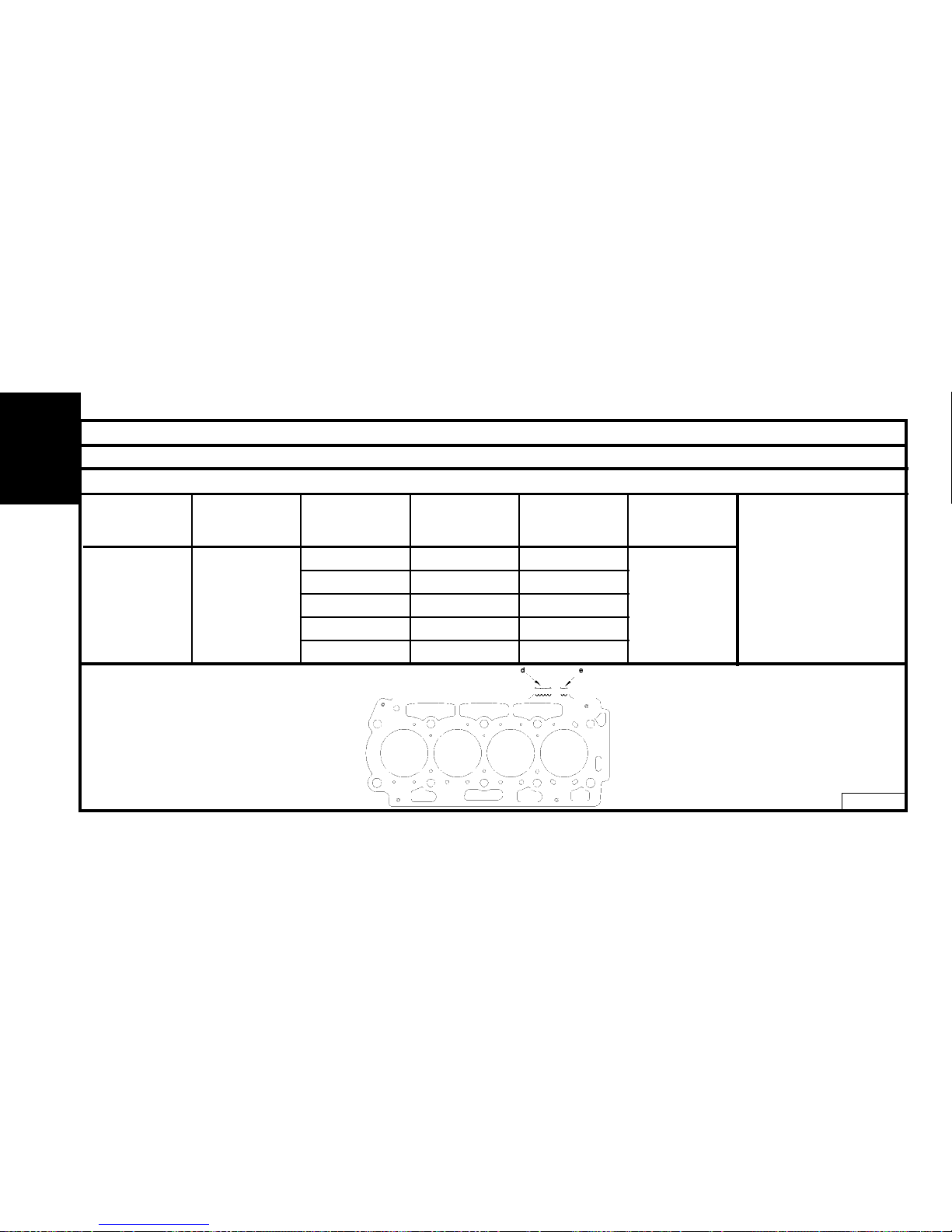
CYLINDER HEAD
Identification of cylinder head gasket
Engine types Supplier
Piston
standproud
(mm)
Thicknesses
(mm)
No. of notches
at d
No. of notches
at e
0.675 to 0.725 1.25 1
0.726 to 0.775 1.30 2
8HY-8HV ELRING 0.776 to 0.825 1.35 3 2
0.826 to 0.875 1.40 4
0.876 to 0.983 1.45 5
B1DP1CKD
Engines : 8HY - 8HV
Type of gasket : Metallic
multilayer
"d" Thickness reference.
"e" Engine reference
Page 51
49
ENGINE
CYLINDER HEAD
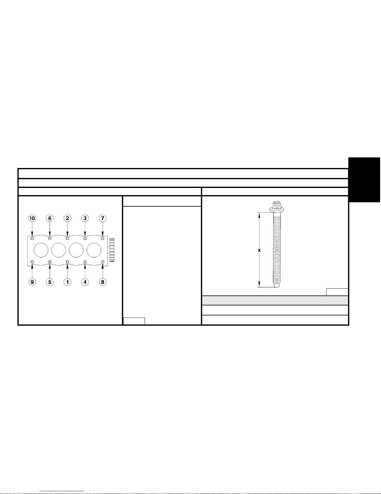
Engines : 8HY - 8HV
Cylinder head tightening (m.daN) Cylinder head bolts
X = MAXIMUM reusable length
Pre-tightening : 2 ± 0.2
Tightening : 4 ± 0.5
Angular tightening : 230 ° ± 5°
(In the order 1 to 10)
NOTE :
- The bolts should have been
thoroughly cleaned and dried
with a dry metal brush.
- Oil the threads and under the
heads of the bolts. (Use engine
oil or Molykote G Rapid Plus).
- Pass a tap into the holes in the
cylinder block.
8HY - 8HV
8HY - 8HV
X = 149 mm
B1DP1CLC
B1DP1DBC
NOTE : Retightening of the cylinder head
after a completed repair is prohibited.
The cylinder head gasket is dry-fitted.
ENGINE
Page 52
50
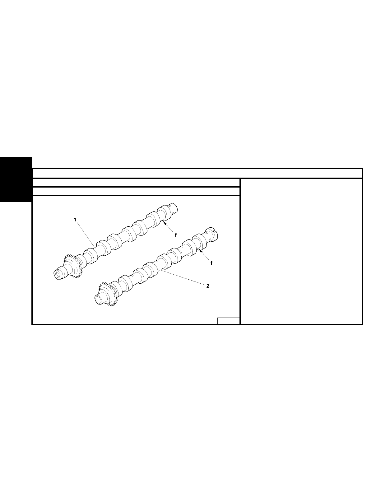
CAMSHAFT
Engines : 8HY - 8HV
Camshaft identification
(1) - Inlet camshaft.
(2) - Exhaust camshaft.
"f" : Marking zone.
B1EP18AD
ENGINE
Page 53
51
ENGINE
Tools
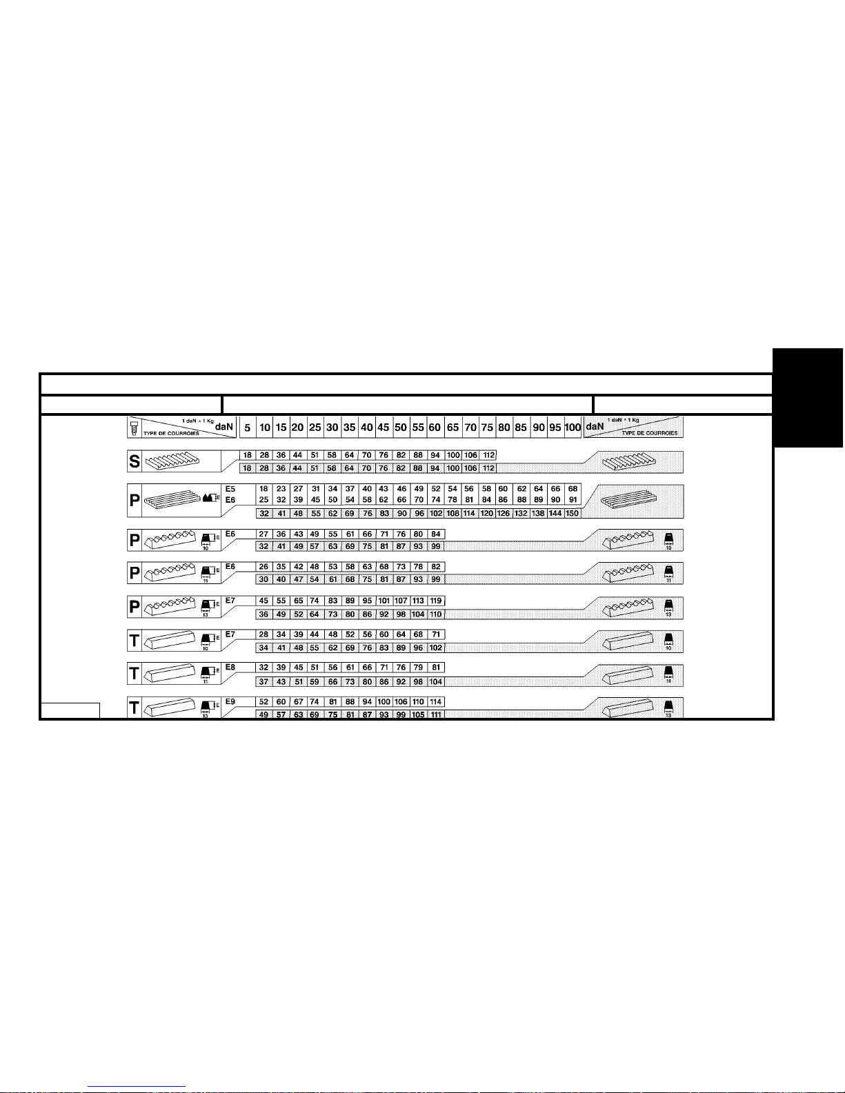
BELT TENSION/SEEM UNITS CORRESPONDENCE TABLE
! 4099-T (C.TRONIC.105)
4122-T (C.TRONIC.105.5)
!
!
!
B1EP135D
Page 54
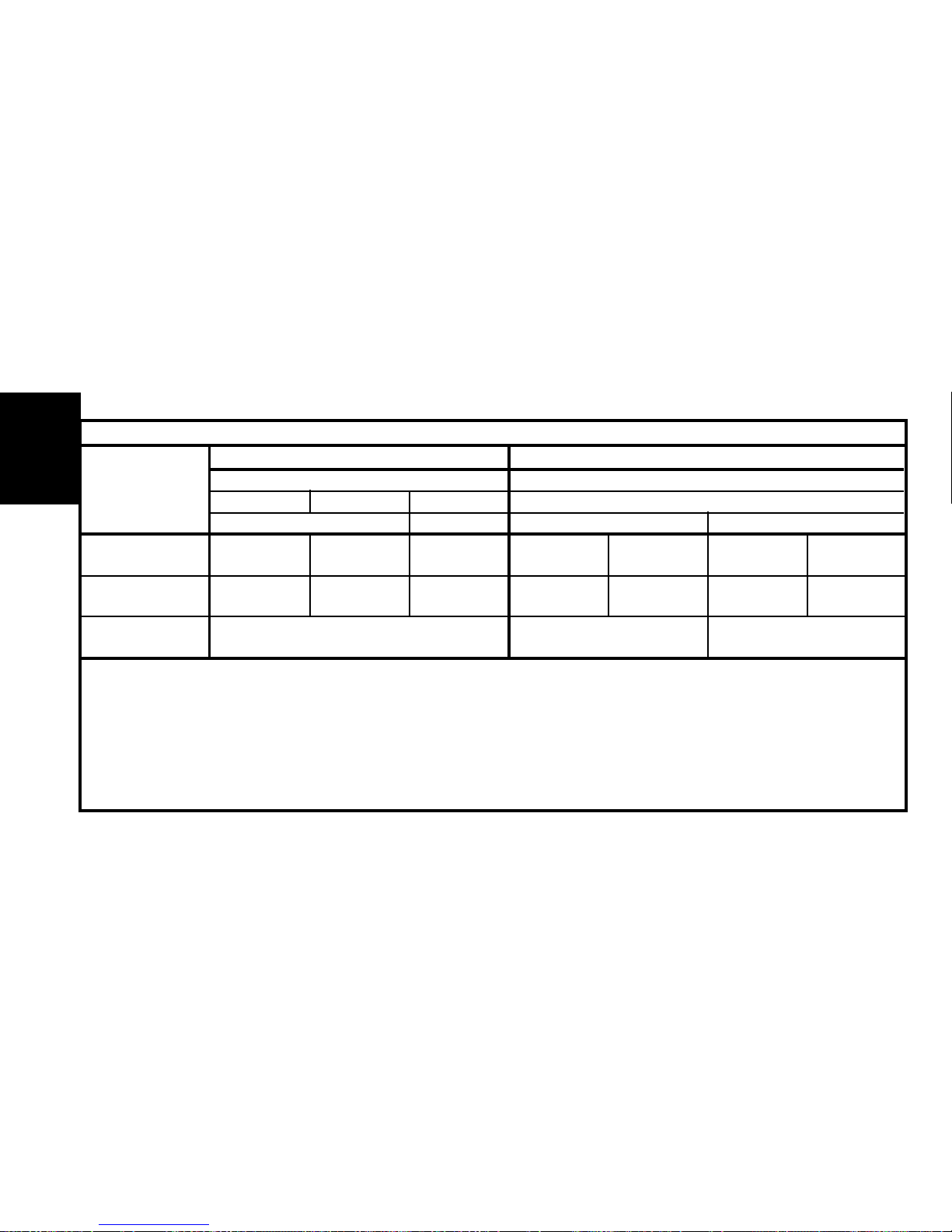
52
Petrol Diesel
TU DV
13 5 4
JP JP4 TD TED4
Engine type HFX KFV NFU 8HX 8HW 8HV 8HYX
C3 X X X X X X X
See pages : 53 to 54 55 to 56 57
AUXILIARY EQUIPMENT DRIVE BELT
ENGINE
Page 55
53
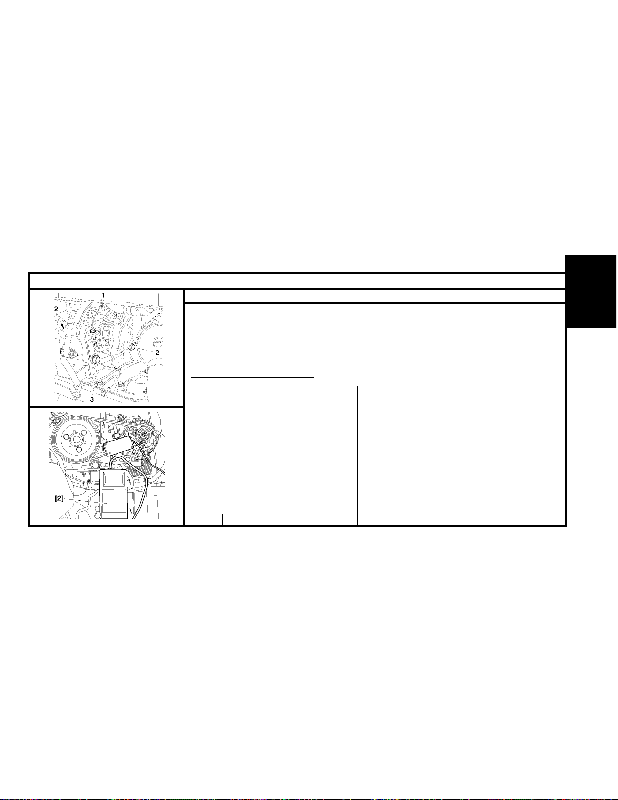
AUXILIARY EQUIPMENT DRIVE BELT
Engines : HFX - KFV - NFU
B1BP2LSC B1BP2LTC
Tools.
[1] Pliers for removing plastic pegs : 7504-T.
[2] Belt tension measuring instrument : 4122-T.
V
ehicle without air conditioning.
Refit.
Refit the belt.
Respect the following sequence:
- Crankshaft pinion.
- Alternator pulley.
Place tool [2] on the belt.
Tighten screw (1) to achieve a tension of:
55 ± 3 unités SEEM.
Tighten:
- Screw (3).
- Screw (2).
Remove tool [2] and complete the refitting.
Remove.
Slacken:
- Screw (2).
- Screw (3).
- Tensioning screw (1).
Push the alternator back towards the engine.
Remove the belt.
ENGINE
Page 56
54
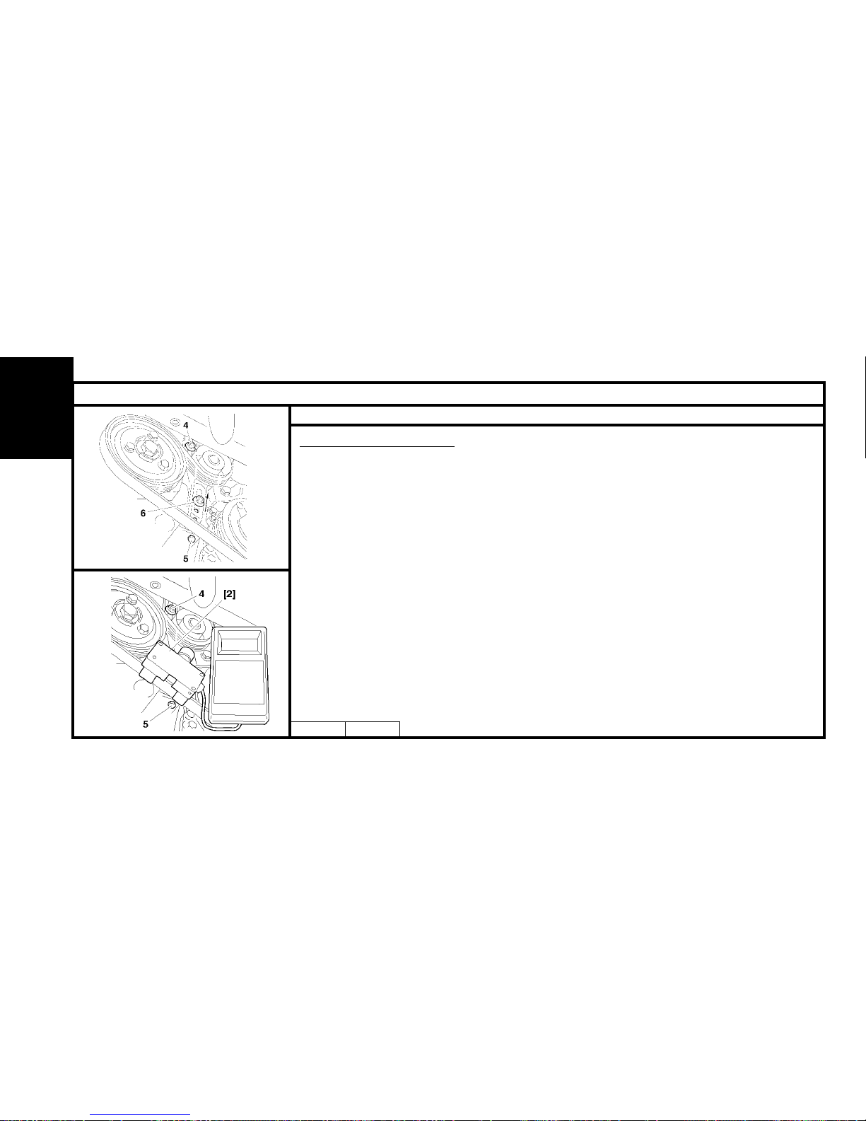
AUXILIARY EQUIPMENT DRIVE BELT
Engines : HFX - KFV - NFU
B1BP10XC
Vehicle with air conditioning.
Remove
Slacken:
- Screws (6), (4) and (5).
- Fully detension the belt by acting on the tensioner roller.
- Remove the accessories drive belt.
Refit.
Respect the following sequence:
- Crankshaft pinion.
- Aircon compressor pulley.
- Guide roller.
- Alternator pulley.
- Tensioner roller.
Place tool [2] on the belt.
- Tighten screw (5) to achieve a belt tension of:
120 ± 3 SEEM units.
- Tighten screws (4) and (6).
- Remove tool [2].
- Complete the refitting.
ENGINE
B1BP10VC
Page 57
55
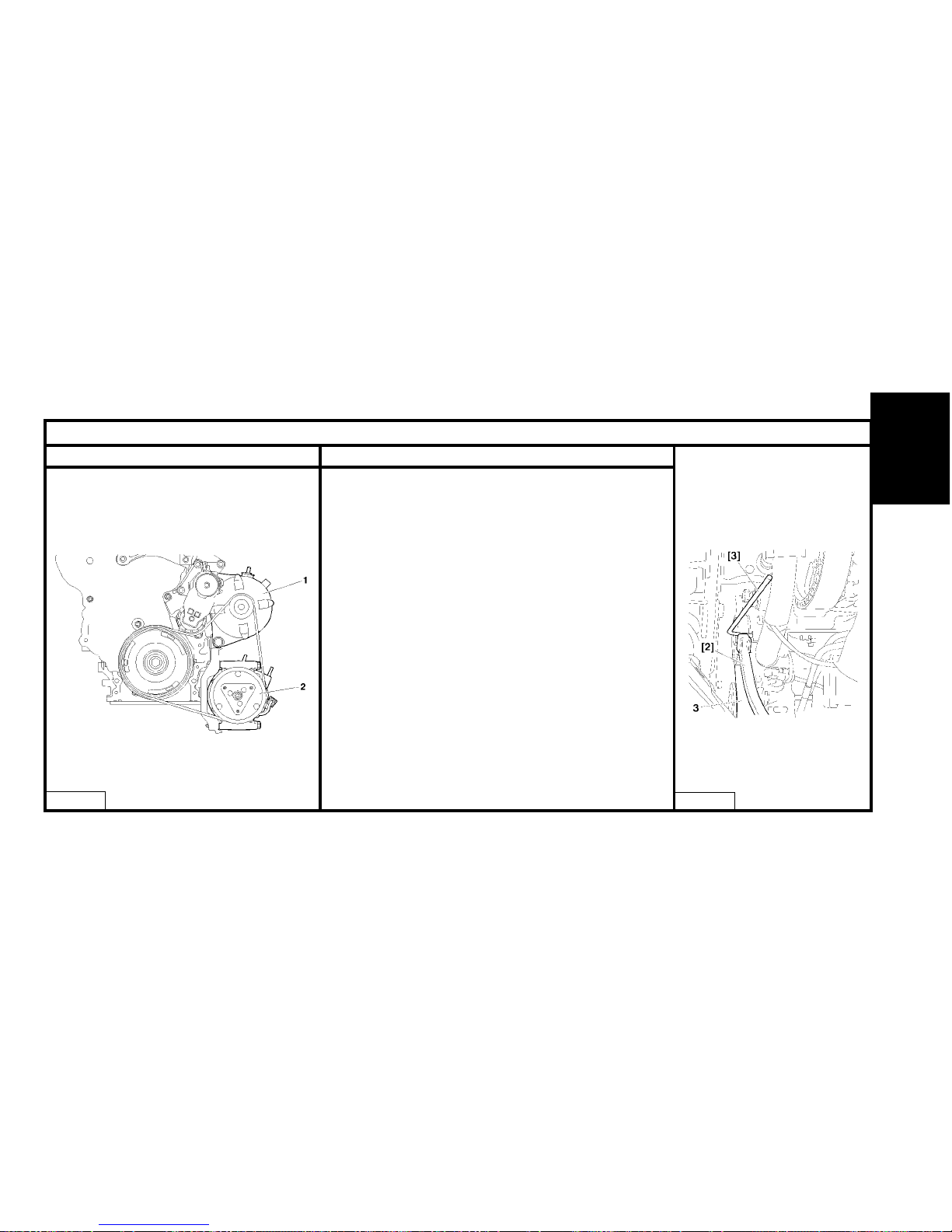
AUXILIARY EQUIPMENT DRIVE BELT
Engines : 8HX - 8HWWith compressor and alternator
B1BP2MKC
B1BP2MJD
Tools
[1] Pliers for removing plastic pegs : 7504-T.
[2] Tensioner roller compression lever : (-).0194.E.
[3] Tensioner roller setting peg Ø4 mm : (-).0194.F.
Removing.
Disconnect the battery negative cable.
Raise and support the vehicle, wheels hanging.
Remove the front RH wheel.
Move aside the splash-shield, using tool [1].
IMPERATIVE : In the case of belt re-use, mark the direction of rotation of the belt. If the index on the tensioner
roller is outside the marks, change the auxiliary equipment
drive belt.
Remove :
The alternator (1).
The aircon compressor (2).
Detension the auxiliary belt tensioner roller, using tool [2].
Position the peg [3]. Remove the auxiliary drive belt.
ENGINE
Page 58
56
AUXILIARY EQUIPMENT DRIVE BELT
Engines : 8HX - 8HW
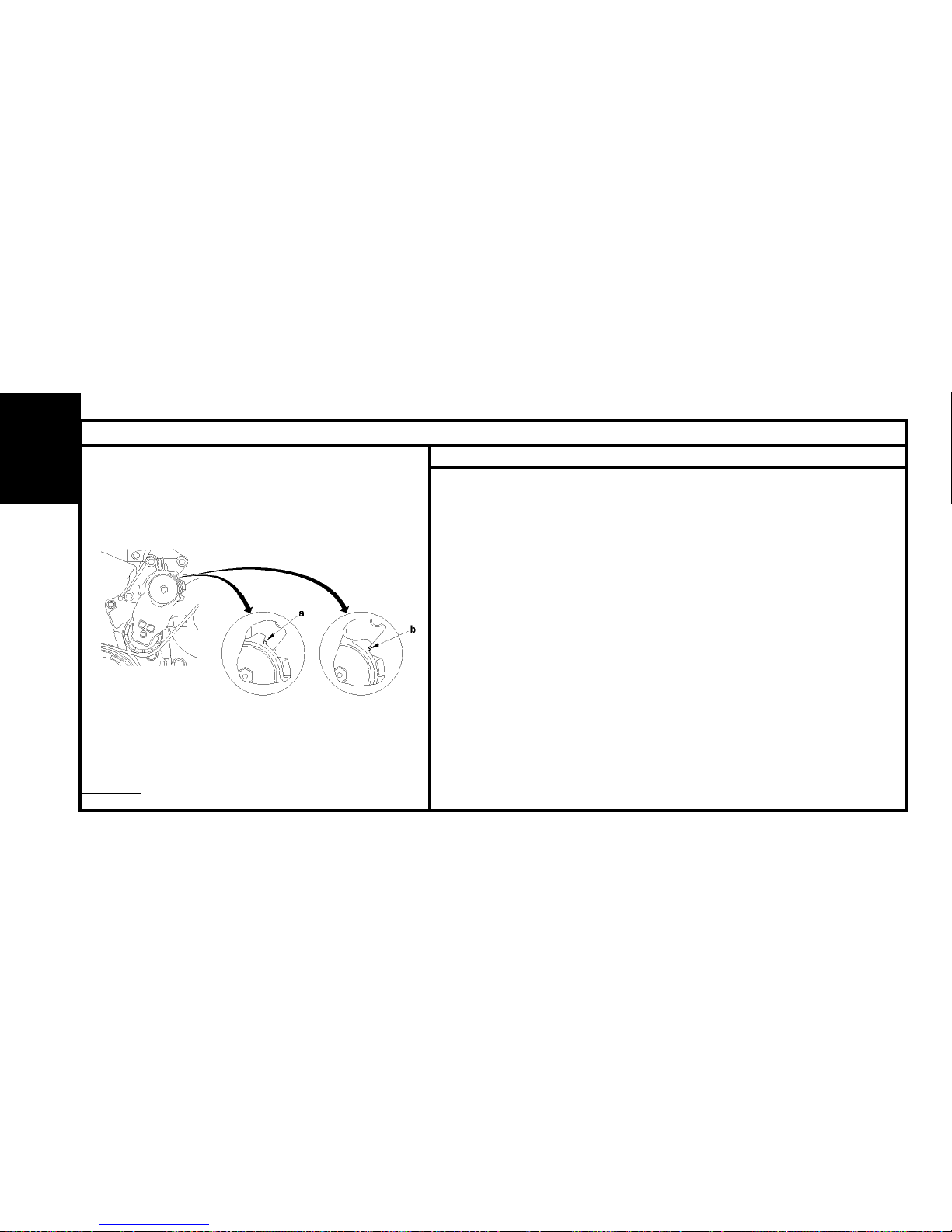
Markings on the dynamic tensioner roller.
"a" Position of «maximum wear» of the auxiliary drive belt.
"b" Normal position.
Refitting
NOTE : Check that the tensioner roller moves freely (no tight spot). If this is not the
case, replace the tensioner roller.
Respect the direction of fitting of the drive belt.
Complete the setting of the belt, of both sides, by means of the tensioner roller.
Make sure that the drive belt is correctly positioned in the «V» grooves of the various
pulleys.
Move the tool [2] on the tensioner roller to remove the peg [3].
ENGINE
B1EP18UD
Page 59
57
AUXILIARY EQUIPMENT DRIVE BELT
Engines : 8HY - 8HV
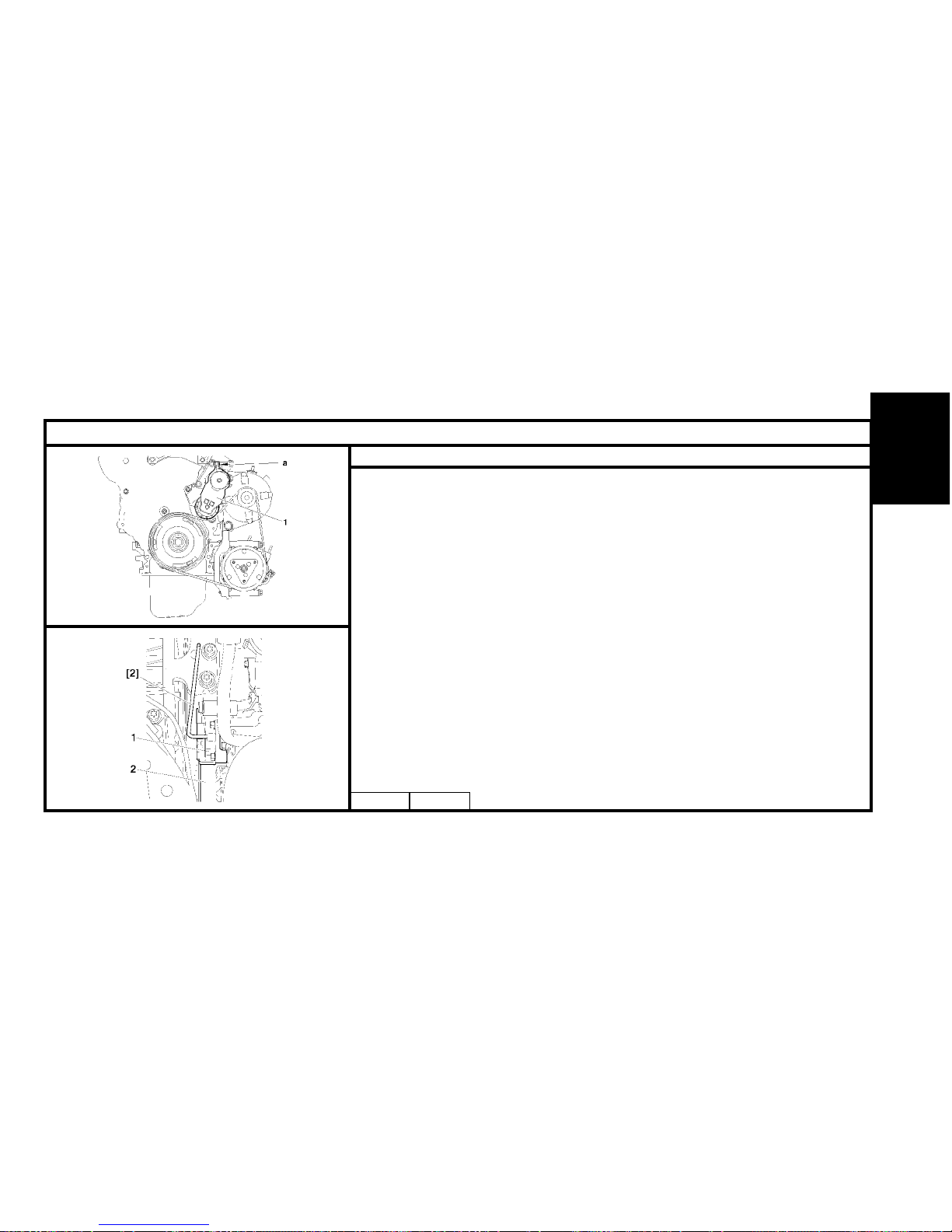
B1BP2MYD B1BP2MZC
Tools.
[1a] Dynamic tensioner roller lever : (-).0194-E1.
[1b] Lever extension : (-).0194-E2.
[2] Accessories belt roller locking peg Ø 4 mm : (-).0194-F
Removing
Pivot the tensioner roller support (1) (clockwise), using tools [1a] and [1b] at «a».
Remove the belt.
Immobilise the support (1) of the tensioner roller, using tool [2].
Remove the auxiliary drive belt (2).
IMPERATIVE : Ensure that the tensioner rollers turn freely (no play, no tight spot).
Refitting
Reposer la courroie.
Move the tool [1] on the tensioner roller to remove the peg [2].
ESSENTIAL: Make sure that the belt is correctly positioned in the various pulley
grooves.
ENGINE
Page 60
58
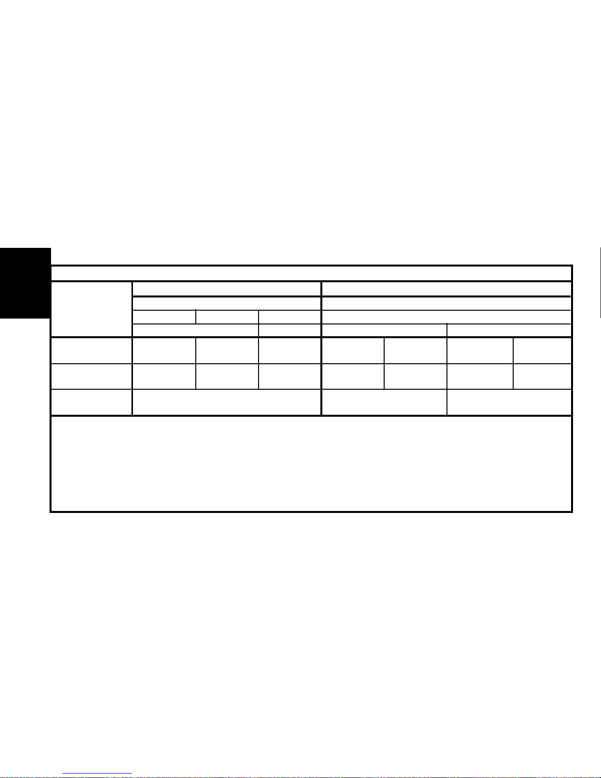
Petrol Diesel
TU DV
13 5 4
JP JP4 TD TED4
Engine type HFX KFV NFU 8HX 8HW 8HV 8HY
C3 X X X X X X X
See pages : 59 to 68 69 to76 77 to 85
CHECKING AND SETTING THE VALVE TIMING
ENGINE
Page 61
59
CHECKING AND SETTING THE VALVE TIMING
Engines : HFX - KFV - NFU
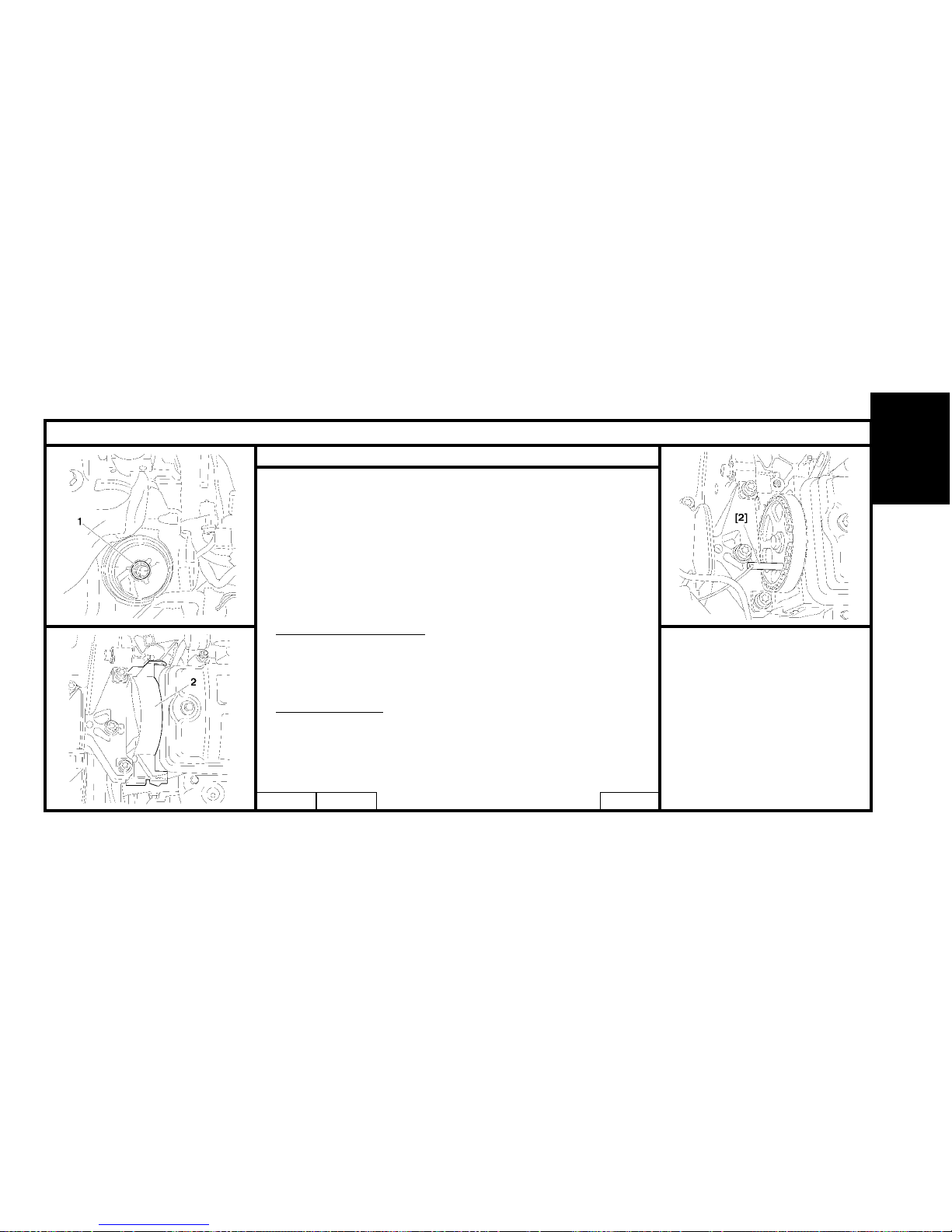
B1BP2M7C B1BP2M9C
B1BP2M8C
Tools.
[1] Engine flywheel peg : 4507-T.A
[2] Camshaft pulley peg : 4507-T.B
[3a] Camshaft peg : 4533-TA.C1
[3b] Camshaft peg : 4533-TA.C2
[4] Dynamic tensioner roller pin : 4200-T.H
[5] Belt retaining pin : 4533-T.AD
[6] Pliers for removing plastic pins : 7504-T.
Checking the valve timing.
Engines HFX - KFV - NFU
Raise and support the front RH side of the vehicle.
Disconnect the battery positive terminal.
Engage 5th gear.
Remove the oil filter (1).
HFX – KFV engine
Remove :
The timing top casing (2).
Turn the wheel to rotate the engine (normal direction of rotation).
Peg the camshaft pulley, using tool [2].
ENGINE
Page 62
60
CHECKING AND SETTING THE VALVE TIMING
Engine : NFU
B1BP2MAC
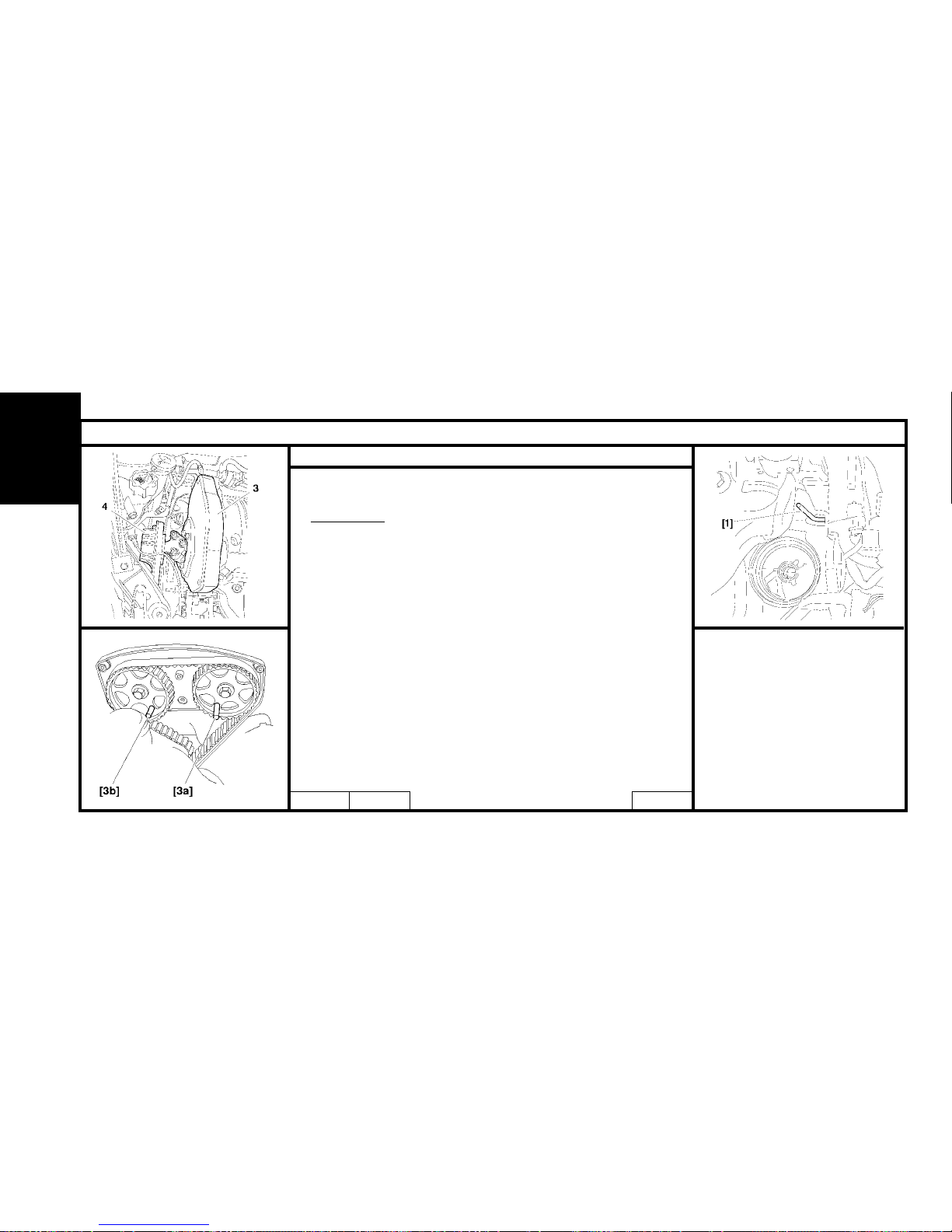
Checking the timing (continued)
Engine: NFU
Place a jack under the engine, peg the engine.
Remove:
- The engine support (4) complete.
- The timing casing (3).
- The sparking plugs (eases engine rotation).
Turn the wheel to rotate the engine (normal direction of rotation).
Position the pegs [3a] and [3b].
Peg the flywheel, using tool [1].
If the setting is not correct, recommence the operation.
Remove the tools [1], [2], [3a] and [3b].
Complete the refitting.
B1BP2MBC
ENGINE
B1EP18MC
Page 63
61
CHECKING AND SETTING THE VALVE TIMING
Engines : HFX - KFV
B1BP2MBCB1BP2M9C B1BP2MDC
Setting the timing
Preliminary operation.
Lift and support the vehicle, wheels hanging.
Disconnect the battery.
Remove:
- The front RH wheel.
- The splash-shield, using tool [6]
- The accessories belt (See corresponding operation).
- The crankshaft pulley.
- The oil filter.
Place a jack under the engine, peg the engine.
Removing.
HFX – KFV engine
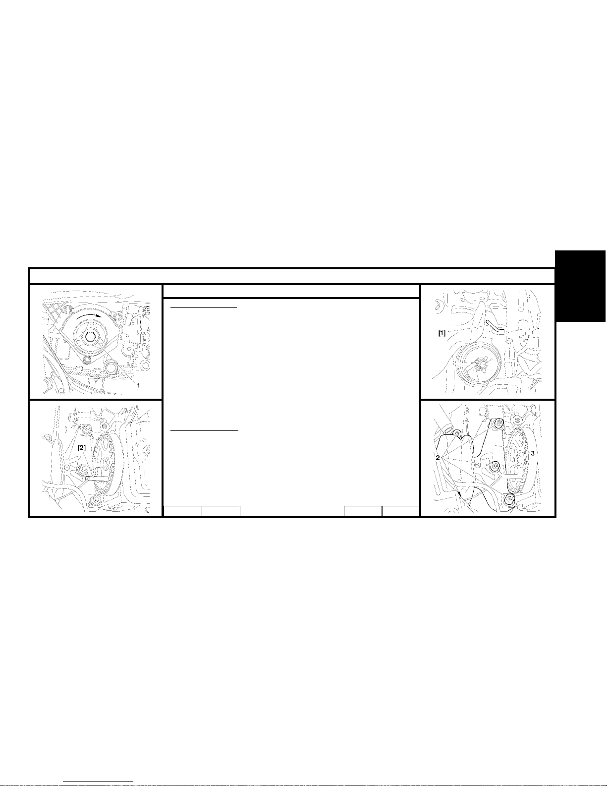
Turn the engine by means of screw (1). (normal direction of rotation).
Remove the timing casings.
Peg the camshaft pinion, using tool [2].
Peg the flywheel, using tool [1].
Remove:
- The fixing screws (2).
- The upper engine support (3).
ENGINE
B1BP2MCC
Page 64
62
CHECKING AND SETTING THE VALVE TIMING
Engines : HFX - KFV
B1BP2MEC B1EP18NC
Setting the timing (continued)
HFX – KFV engines
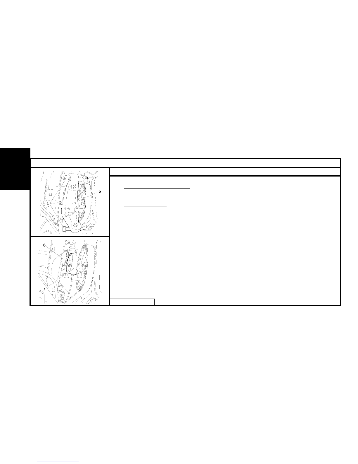
Slacken the screws (4) without removing them.
Remove the bottom engine support assembly (5), and the fixing screws (4).
Slacken the nut (6).
Completely detension the belt by acting on the tensioner roller (7).
Remove the timing belt.
IMPERATIVE : Check that the tensioner roller turns freely (no tight spot).
ENGINE
Page 65
63
CHECKING AND SETTING THE VALVE TIMING
Engine : NFU
B1BP2MBC
NFU engine.
Setting the timing (continued)
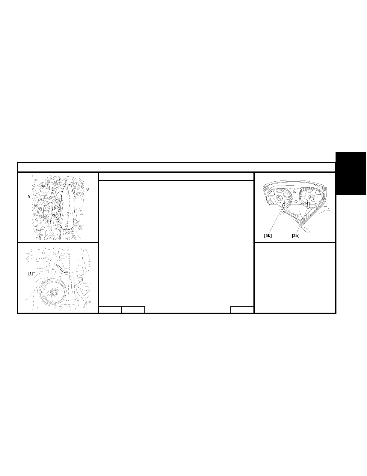
Remove:
The bottom plastic casing.
The engine support (9).
The middle support.
The timing cover (8).
Peg the flywheel, using tool [1].
Position the tools [3a] and [3b].
ENGINE
B1BP2MFC B1EP18MC
Page 66
64
CHECKING AND SETTING THE VALVE TIMING
Engine : NFU
B1EP18PC
Setting the timing (continued)
NFU Engine
Slacken the tensioer roller.
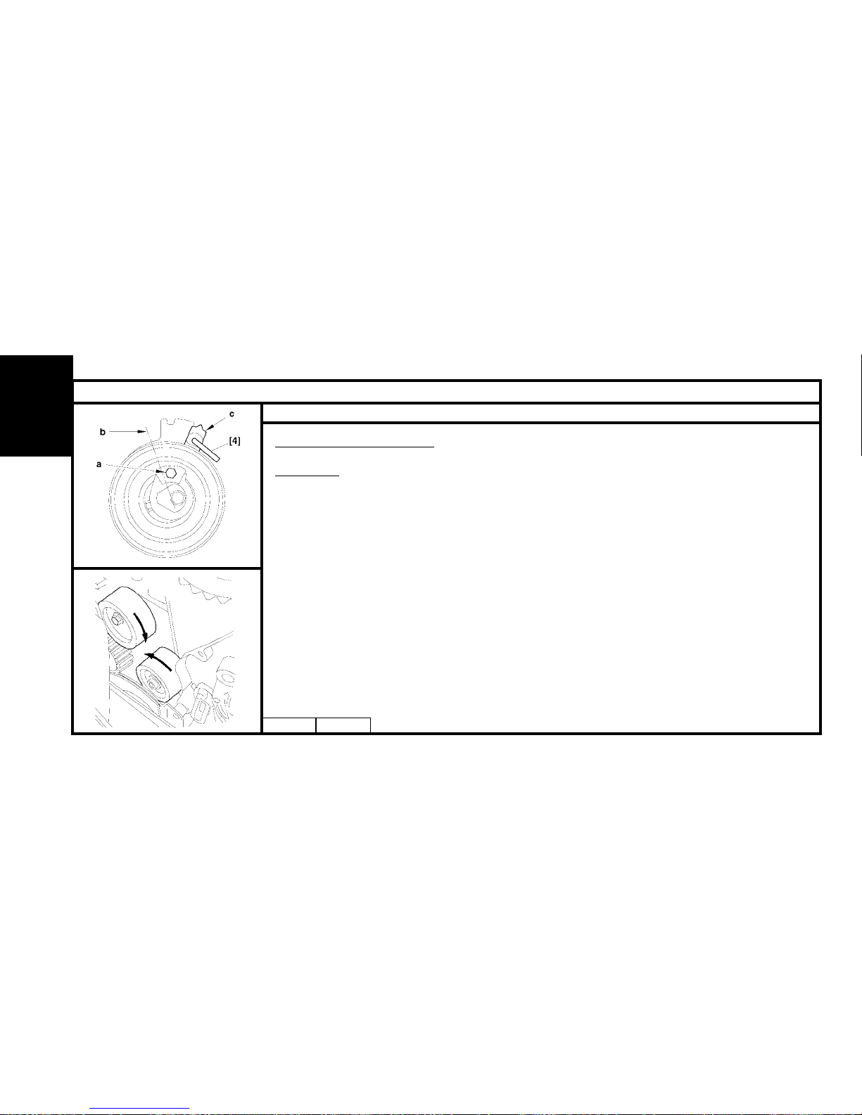
Turn the tensioner roller so as to be able to position the tool [4], with the aid of an Allen key placed at «a».
Turn the tensioner roller towards the right to bring it to the index «c» in position «b».
Peg the tensioner roller in this position in order to slacken the timing belt to the maximum.
IMPERATIVE : Never make the dynamic tensioner roller turn by a complete rotation.
Remove the timing belt (8).
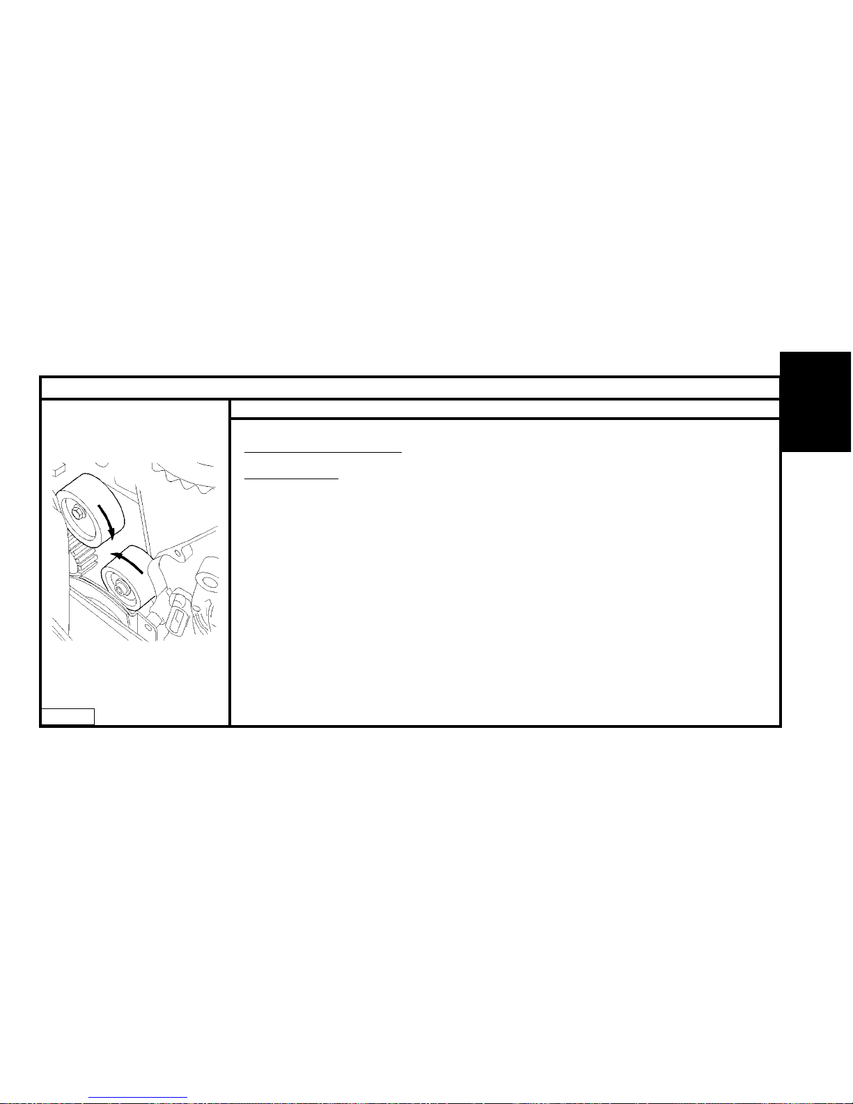
Check that the rollers (9) and (10) turn freely (no tight spot).
ENGINE
B1EP18QC
Page 67
65
CHECKING AND SETTING THE VALVE TIMING
Engines : HFX - KFV
B1EP18QC
Setting the timing (continued)
HFX-KFV Engines
Refit.
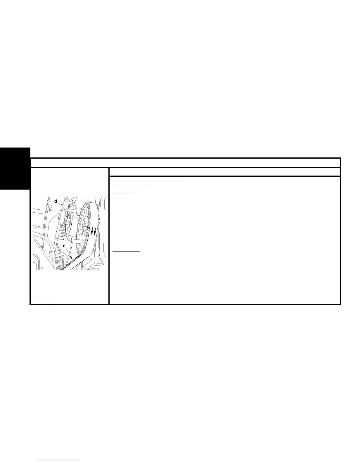
WARNING: Respect the direction of fitting of the belt: (the arrows «d» indicate the direction of rotation of
the crankshaft).
Refit the timing belt.
Position the timing belt, belt «e» well tensioned, in the following order:
Crankshaft pinion, hold the belt using tool [5].
Camshaft pulley.
Coolant pump pulley.
Tensioner roller.
Remove the pegs [1] and [2].
ENGINE
Page 68
66
CHECKING AND SETTING THE VALVE TIMING
Engines : KFX - KFV - NFU
Setting the timing (continued)
HFX-KFV engines
Refitting.
NOTE : Check that the pegs [1] and [2] are in place.
WARNING: Respect the direction of fitting of the timing belt, the arrows «d» indicate the direction of rotation
of the crankshaft.
Refit the timing belt.
Position the timing belt, belt «e» well tensioned, in the following order:
Crankshaft pinion, hold the belt using tool [5].
- Camshaft pulley.
- Coolant pump pulley.
- Tensioner roller.
Remove the tools [1], [2].
NFU engine.
Fit the timing belt in position in the following order:
- Inlet camshaft pulley.
- Exhaust camshaft pulley.
- Guide roller.
- Crankshaft pulley.
Position tool [5].
- Coolant pump pulley.
- Dynamic tensioner roller.
Remove the tools [1], [3] and [5].
ENGINE
B1EP18RC
Page 69
67
CHECKING AND SETTING THE VALVE TIMING
Engine : NFU
B1EP18SD
Timing belt overtensioned:
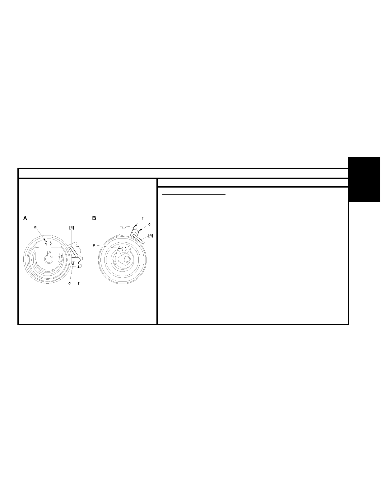
A: Engines HFX – KFV.
B : Engine NFU
Turn the tensioner roller (7) with the aid of a hexagonal spanner at «a».
Bring the index «c» to position «f», to tension the belt to the maximum of the
interval indicated.
Hold the tensioner roller (7), using tool [4].
Tighten the fixing nut of the tensioner roller, tightening to 1 ± 0,1 m.daN.
Turn the crankshaft by 4 rotations (normal direction of rotation).
IMPERATIVE : Never make the crankshaft rotate backwards.
Make sure that the timing is correctly set by refitting the tools [1], [2] and [3].
Remove the tools [1], [2] and [3].
ENGINE
Page 70
68
CHECKING AND SETTING THE VALVE TIMING
Engines : HFX - KFV - NFU
B1EP18TD
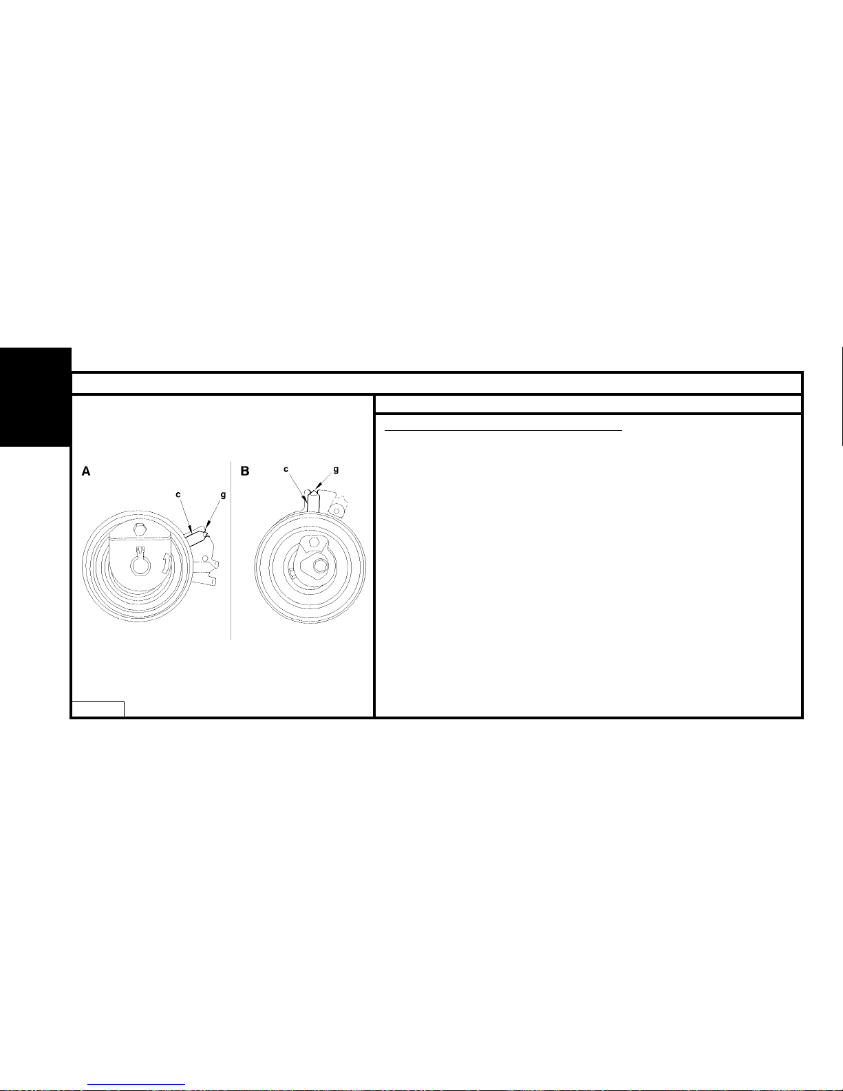
Adjusting the fitting tension of the timing belt
A: Engines HFX – KFV.
B : Engine NFU.
Slacken the nut while maintaining the position of the tensioner roller, with the aid of
a hexagonal spanner at «a».
Next bring the index «c» to its adjusting position «a».
The index «c» should not go beyond the notch «g».
WARNING: The index «c» must not go beyond the notch «g». If it should do this, restart
the timing belt tensioning operation.
Hold the tensioner roller (7) in this position, with the aid of a hexagonal spanner.
Tighten the tensioner roller fixing nut to :
2 ± 0.2 m.daN. (HFX - KFV engines)
2.2 ± 0.2 m.daN. (NFU engines)
IMPERATIVE : The tensioner roller must not rotate during the tightening of its
fixing. If it does, restart the timing belt tensioning operation.
Complete the refitting.
ENGINE
Page 71
69
CHECKING AND SETTING THE VALVE TIMING
Engines : 8HX - 8HW
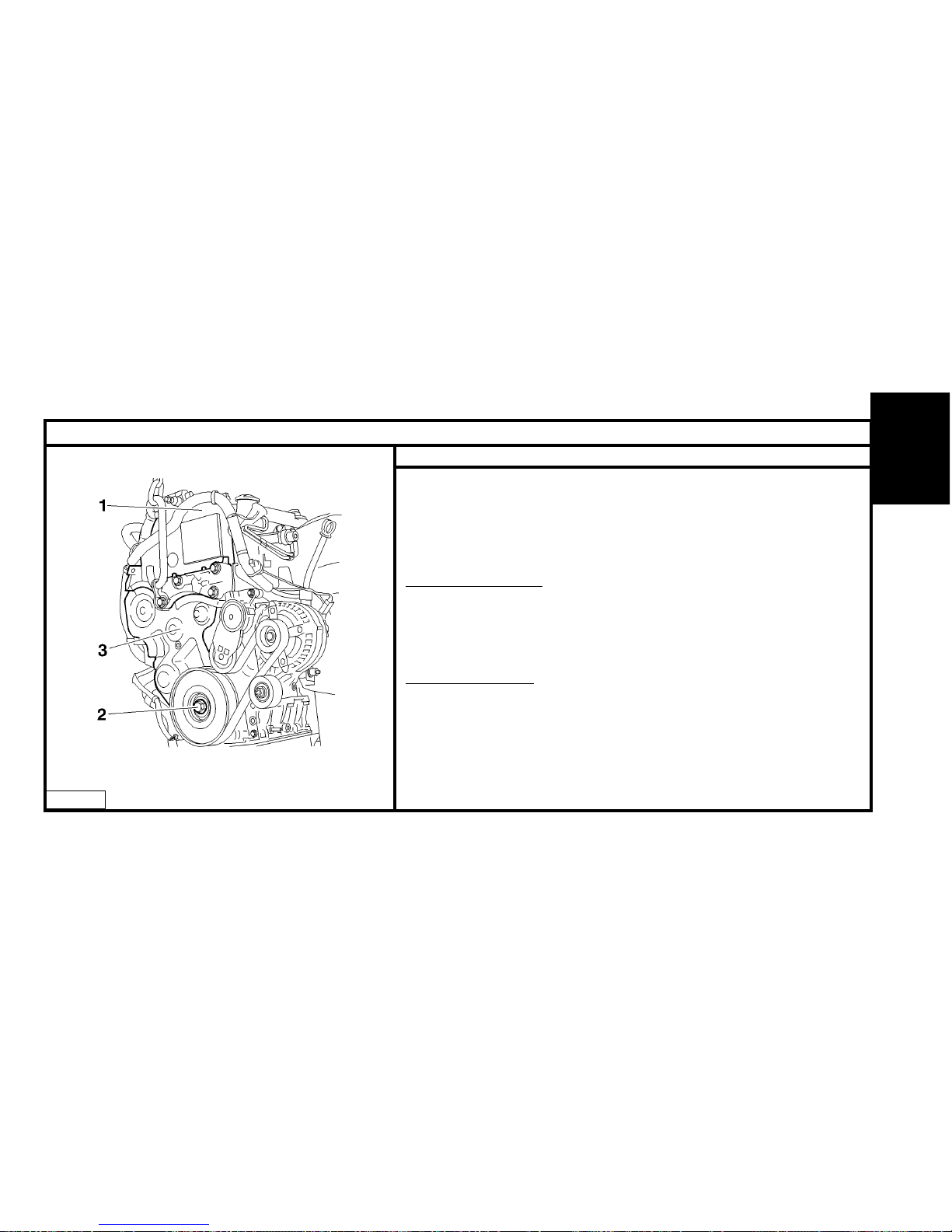
B1BP2LXC
Tools.
[1] Pliers for removing plastic pegs : 7504-T.
[2] Lever for detensioning the dynamic tensioner roller : (-).0194.E
[3] Engine flywheel setting peg :.(-).0194.C
[4] Camshaft setting peg : (-).0194.B.
[5] Crankshaft and high pressure pump setting peg : (-).0194.A.
Preliminary operations.
Remove:
- The front RH wheel.
- The front RH splash-shield, using tool [1].
- The clips of the electrical harness on the upper timing cover.
- The accessories belt, using tool [2] (see corresponding operation).
Check ing the setting.
Disconnect the battery negative cable.
Remove the upper timing cover (1).
Rotate the engine using the screw (2) of the crankshaft pulley.
NOTE : The locking hole is located under the crankshaft bearing cap cover.
Undo the screw (2).
Detension the auxiliary drive belt dynamic tensioner roller, using tool [2].
ENGINE
Page 72
70
CHECKING AND SETTING THE VALVE TIMING
Engines : 8HX - 8HW
B1EP18EC
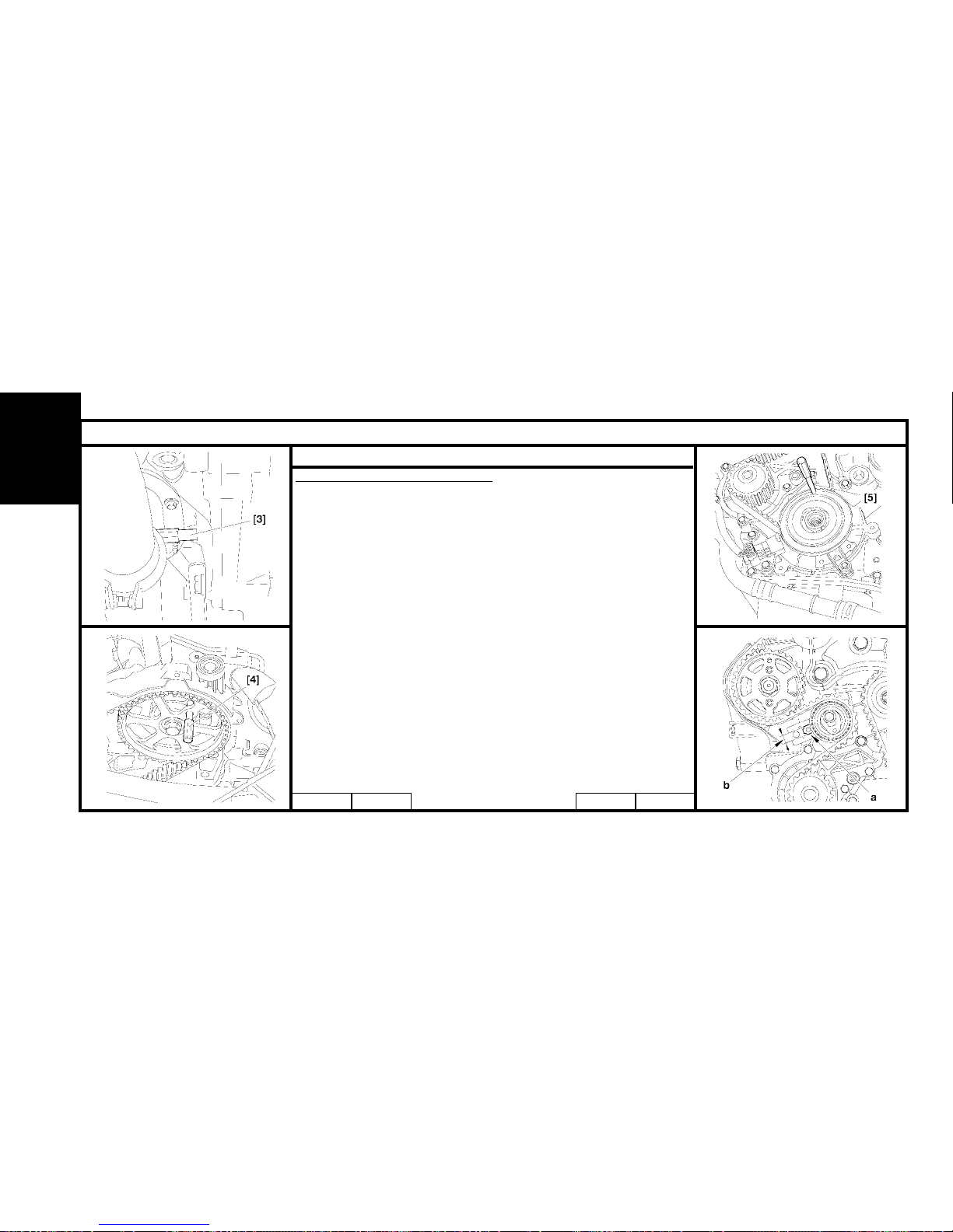
Check ing the setting (continued)
Remove:
- the accessories drive belt.
- the accessories drive pulley.
- the lower timing cover (3).
IMPERATIVE : The magnetic track should show no signs of
damage and should not be approached by any other source of
magnetism.
Reposition the screw (2).
Remove tool [3].
Rotate the engine by means of the crankshaft pinion screw (2)
(clockwise), to bring it to the pegging position.
Position the tool [4].
Peg the crankshaft pinion (1), using tool [5].
Peg the high pressure pump pinion, using tool [5].
NOTE : Index «a» of the roller tensioner must be centred within
the area «b».
Check the correct positioning of i ndex «a».
Remove tools [4] and [5].
Rotate the engine ten times.
Fit the tools [4] and [5].
If pegging is not possible, carry out the operation to remove/refit the
timing belt. (See corresponding operation).
B1JP03SC
B1EP18DC
B1EP18FC
ENGINE
Page 73
71
CHECKING AND SETTING THE VALVE TIMING
Engines : 8HX - 8HW
B1EP18GC
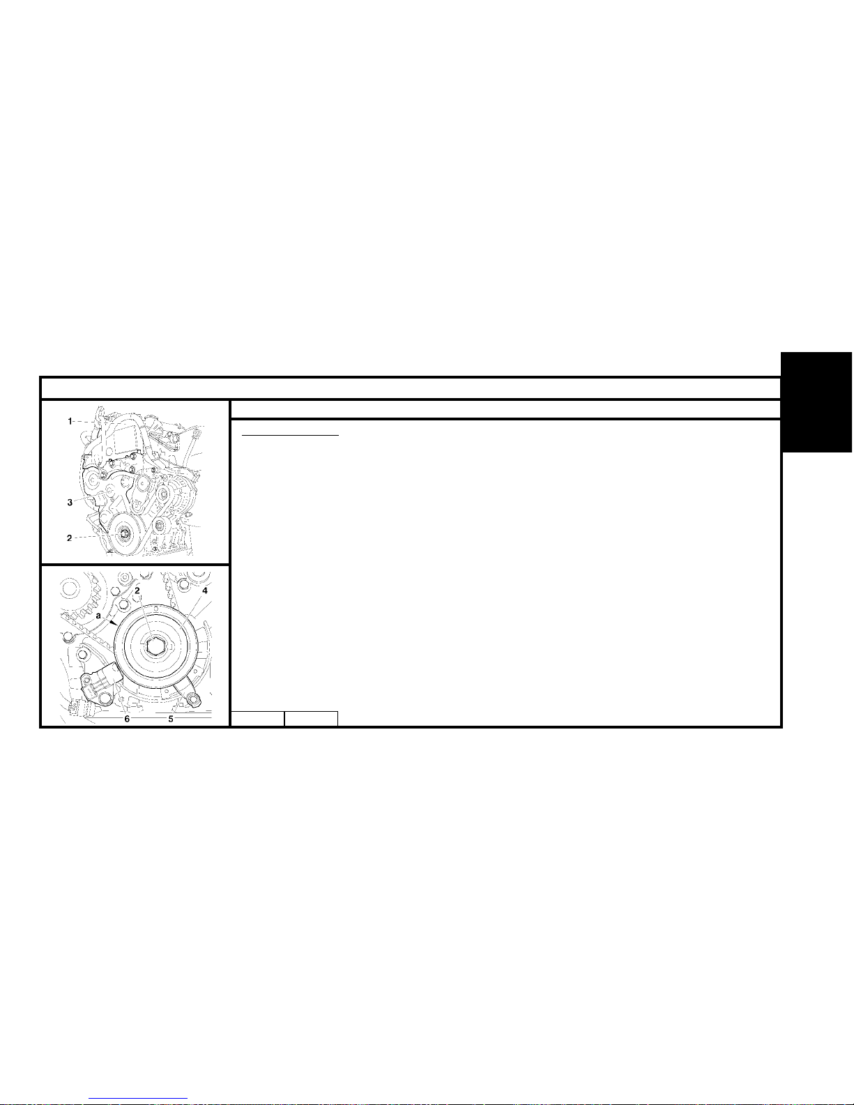
Setting the timing.
Remove the upper timing cover (1).
Rotate the engine by means of the crankshaft screw (2).
NOTE : The pegging hole is located under the crankshaft bearing cap cover.
Peg the engine flywheel, using tool [3].
Remove the lower timing cover (3).
Uncouple the exhaust line from the manifold.
IMPERATIVE : Uncouple the exhaust line in order to avoid damaging the front flexible pipe. Twisting,
pulling and bending the front flexible pipe reduces its life.
Remove:
- The engine speed sensor (6).
- The belt retaining stop (5).
- The screw (2).
- The crankshaft pinion (4) (with its magnetic track «a»).
IMPERATIVE : The magnetic track should show no signs of damage and should not be approached
by any other source of magnetism. Should this not be adhered to, it is essential to replace the
crankshaft pinion.
Refit the screw (2).
ENGINE
B1BP2LXC
Page 74
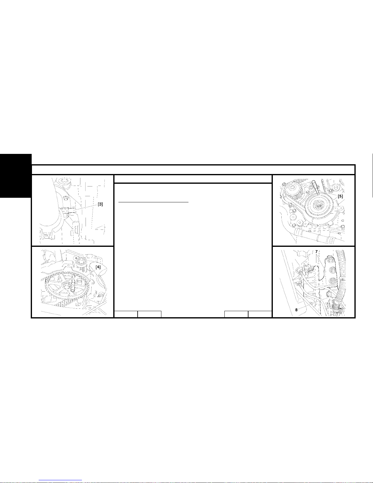
72
CHECKING AND SETTING THE VALVE TIMING
Engines : 8HX - 8HW
Setting the timing (continued).
Remove the tool [3].
Rotate the engine by means of the crankshaft pinion screw (2)
(clockwise), to bring it to the pegging position.
Peg the camshaft pulley, using tool [4].
Peg :
- The crankshaft pinion (6), using tool [5].
- The high pressure pump pinion, using tool [5].
Support the engine with the aid of a roller jack equipped with a chock.
Remove:
- The RH engine support (7).
- The intermediate engine support (right hand side) (8).
B1JP03SC B1EP18DC B1EP195C B1BP2LYC
ENGINE
Page 75
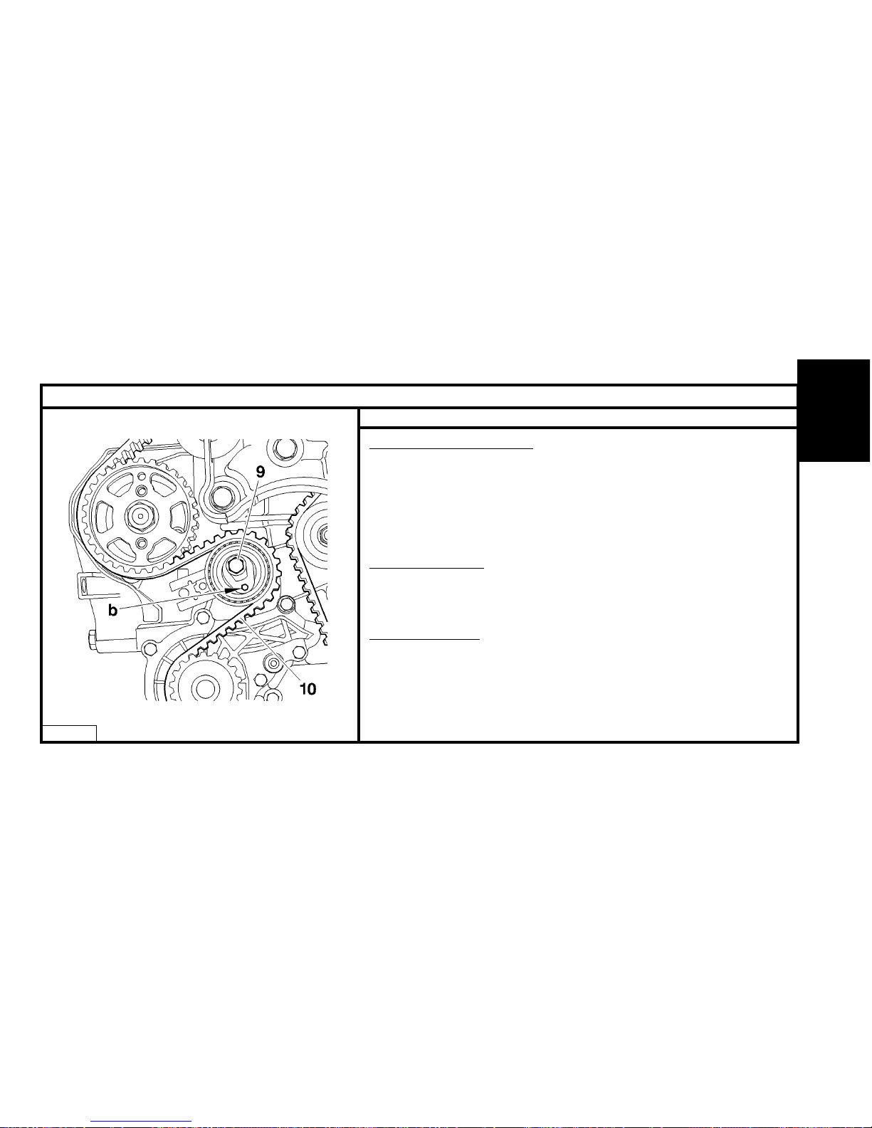
73
CHECKING AND SETTING THE VALVE TIMING
Engines : 8HX - 8HW
B1EP18HC
Setting the timing (continued).
Hold the tensioner roller, using a hexagonal spanner at «b».
Slacken the screw (9).
Remove the timing belt (10).
Refitting.
IMPERATIVE : Check that both the tensioner roller and the fixed roller turn freely
(no tight spots). If this is not the case, replace the rollers.
Fitting of the pulleys.
- Camshaft pulley Tighten to 4.3 ± 0.4 m.daN.
- Fuel high pressure pump pulley Tighten to 5 ± 0.5 m.daN.
The crankshaft pinion is located without a screw at the end of the crankshaft.
Fitting of the rollers.
IMPERATIVE : Check that the tensioner roller turns freely (no tight spot).
Otherwise, replace the rollers.
- Guide roller Tighten to 4.5 ± 0.4 m.daN
- Tensioner roller Pre-tighten to 0.1 m.daN
Check the condition of the seals at the camshaft and at the crankshaft pinion..
ENGINE
Page 76
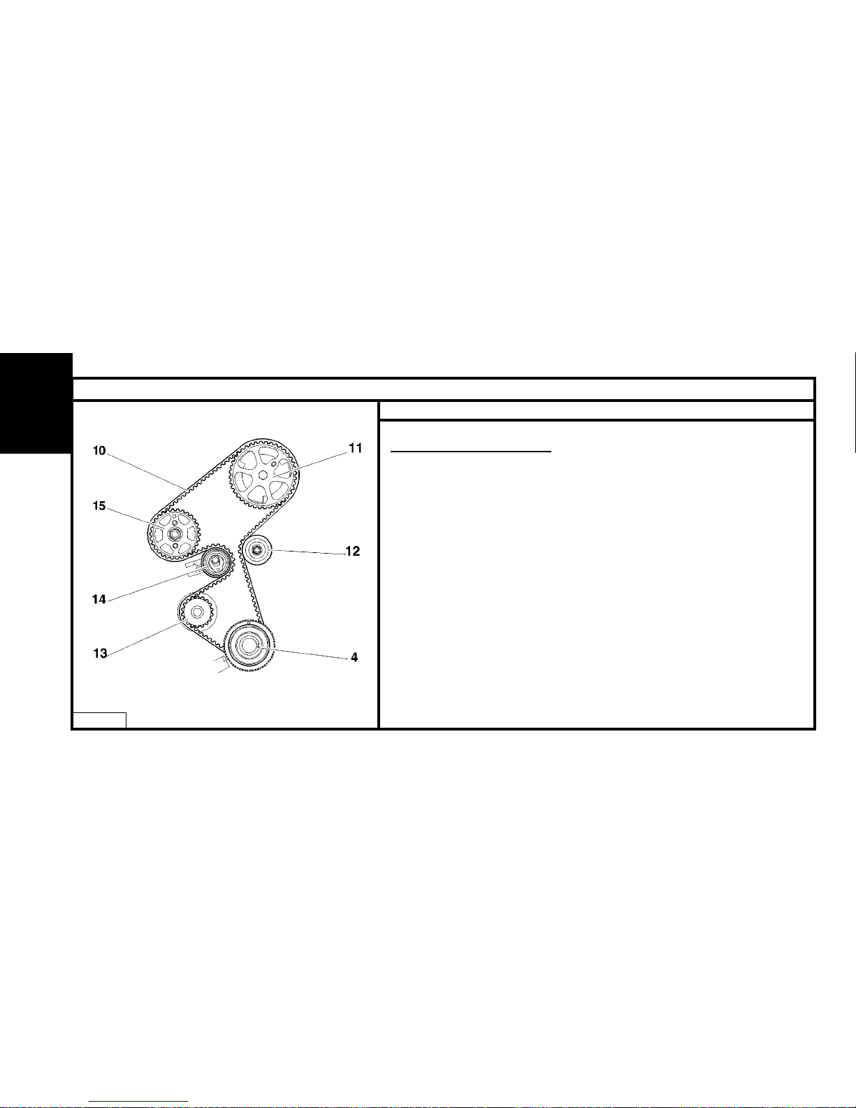
74
CHECKING AND SETTING THE VALVE TIMING
Engines : 8HX - 8HW
B1EP18JD
Setting the timing (continued).
NOTE : Screw (9) slackened.
Position the timing belt (10) observing the following sequence:
Crankshaft pinion (4).
Guide roller (12).
Camshaft pulley (11), (check that the belt is held correctly against the roller).
Coolant pump pinion (13).
Fuel high pressure pump pulley (15).
Tensioner roller (14).
ENGINE
Page 77
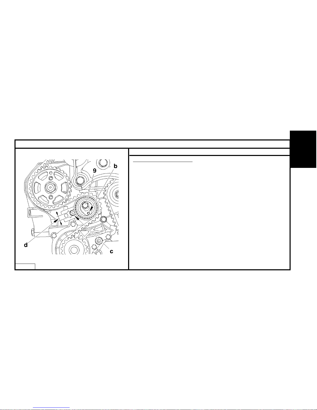
75
ENGINE
CHECKING AND SETTING THE VALVE TIMING
Engines : 8HX - 8HW
B1EP18KC
Setting the timing (continued).
Turn the tensioner roller to the right to bring the index «c» to position «d», using a
hexagonal spanner.
Tighten the screw (9) of the tensioner roller, tighten to 3 ± 0.3 m.daN.
Remove the tools [4] and [5].
Rotate the engine ten times (check that the timing pinion is correctly up against the
crankshaft)..
Check:
The pegging of the camshaft.
The crankshaft pinion.
The fuel high pressure pump pinion (15).
The correct positioning of the index of the dynamic tensioner.
If these are not correct, repeat the operation to position the timing belt.
Refit:
The engine speed sensor (6).
The belt retaining stop (5), tighten to 0,7 m.daN.
Page 78
76
CHECKING AND SETTING THE VALVE TIMING
Engines : 8HX - 8HW
B1EP18LC B1BP2LZC
Setting the timing (continued).
Refit:
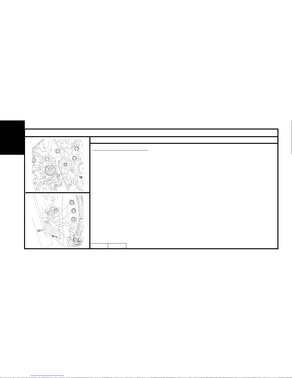
The intermediate RH engine support, tighten the screws (16) to 5,5 ± 0,5 m.daN.
The RH engine support, tighten the screws (17) to 4,5 ± 0,4 m.daN.
The bottom timing cover (3).
Immobilise the engine flywheel, using tool [3].
Remove the screw (2).
Refit the accessories drive pulley and tighten to:
Pre-tighten to : 3 ± 0,3 m.daN.
Angular tighten to : 180° ± 1°,8’
Remove tool [3].
Refit:
The top cover (1).
The accessories belt (see corresponding operation).
The exhaust line (see corresponding operation).
The front RH splash-shield.
The front RH wheel.
ENGINE
Page 79
77
CHECKING AND SETTING THE VALVE TIMING
Engines : 8HY - 8HV
B1BP2N0C
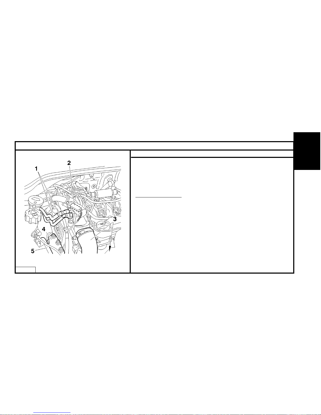
Tools.
[1] Engine flywheel peg Ø 12 mm : (-).0194-C.
[2] Camshaft pulley peg Ø 8 mm : (-).0194-B.
[3] Crankshaft pulley peg Ø 5 mm : (-).0194-A.
Preliminary operations.
Remove:
- The front RH wheel.
- The front RH splash-shield.
- The accessories belt (see corresponding operation).
Uncouple:
- The supply unions (1).
- The air/air heat exchanger inlet/outlet pipes (3).
- The exhaust line (at the flexible pipe).
Disconnect the connector (2).
Support the engine by means of a roller jack equipped with a chock.
Remove the engine supports (4) and (5).
ENGINE
Page 80
78
CHECKING AND SETTING THE VALVE TIMING
Engines : 8HY - 8HV
B1BP2N1C B1BP2N2C
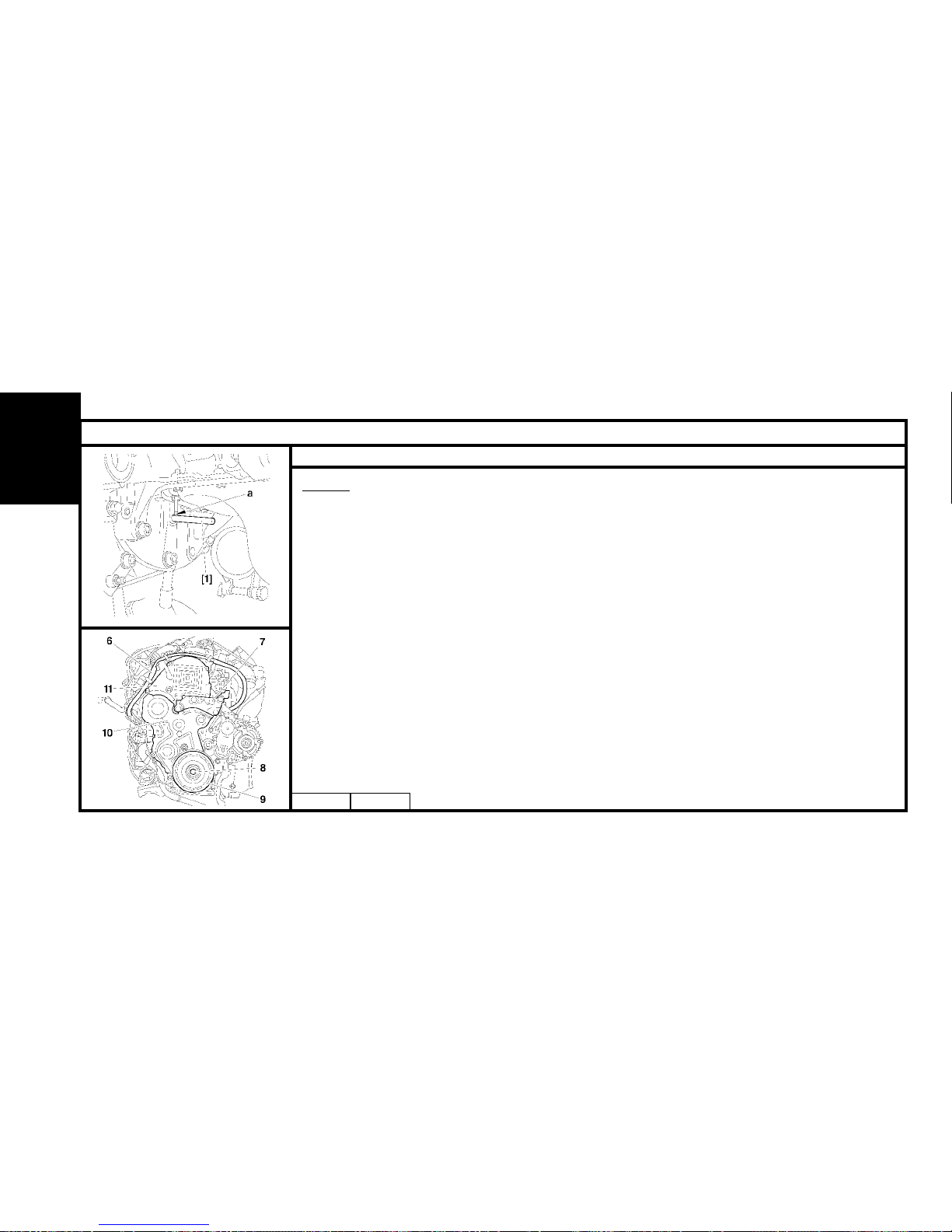
Checks.
Rotate the engine to engage it (normal direction of rotation).
Immobilise the engine flywheel at «a», using tool [1].
Move aside the harness (6).
Remove:
- The engine support (7).
- The screw (8).
- The pulley (9).
- The lower timing cover (10).
- The upper timing cover (11).
- The tool [1].
ENGINE
Page 81
79
CHECKING AND SETTING THE VALVE TIMING
Engines : 8HY - 8HV
B1EP18YD
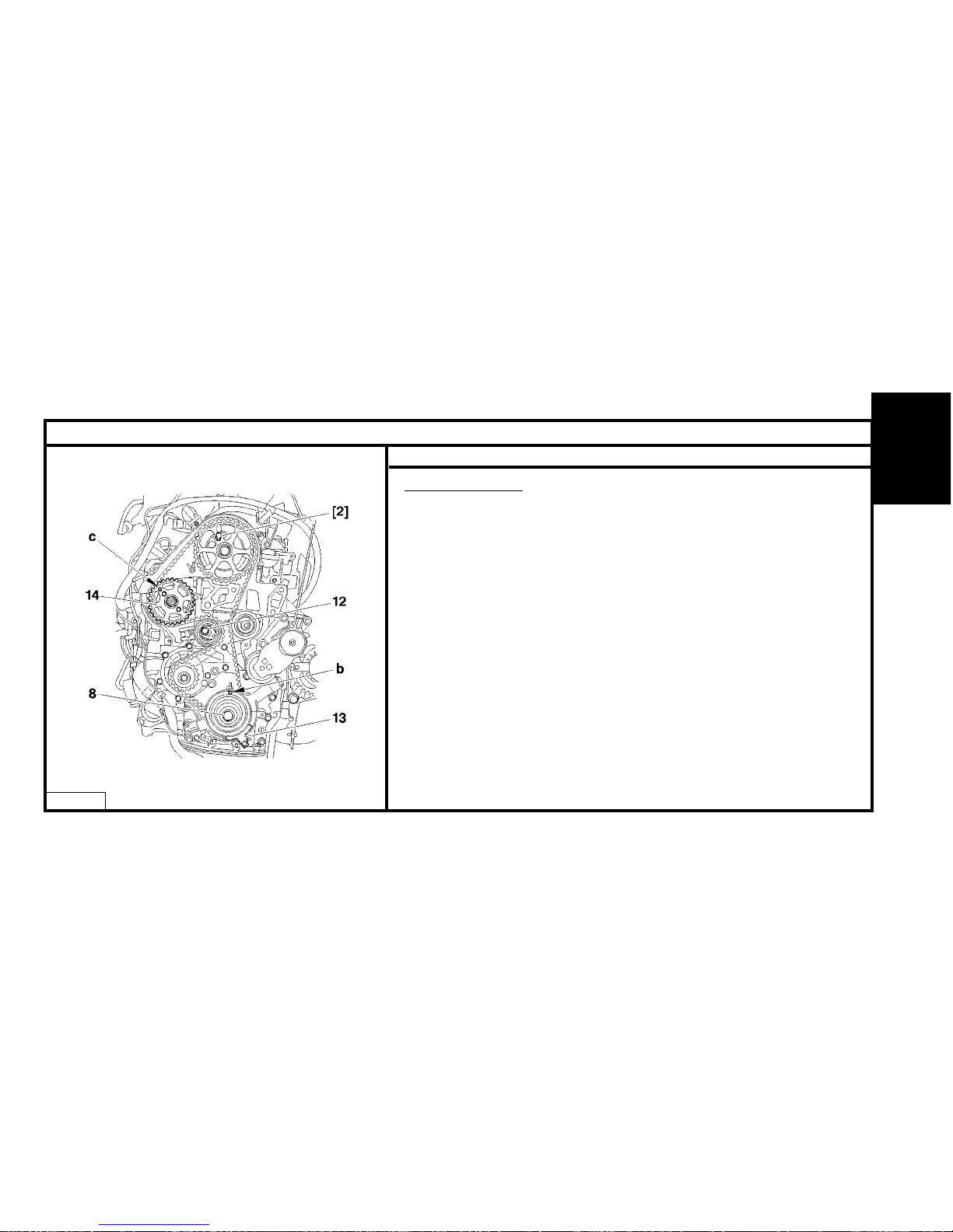
Checks (continued).
Refit the screw (8).
Rotate the crankshaft six times (clockwise).
IMPERATIVE : Never rotate the engine backwards.
Peg :
- The camshaft, using tool [2]. (Oil the pegs.)
- The fuel high pressure pump pulley (14), using tool [3] at «c».
WARNING: The magnetic track should show no signs of damage and should not
be approached by any source of magnetism.
Peg the crankshaft at «b», using tool [3].
IMPERATIVE: Should it be impossible to peg the camshaft, check that the
offset between the hole in the camshaft pinion and the pegging hole is not
greater than 1 mm.
Otherwise repeat the operation to position the timing belt. (See corresponding
operation).
ENGINE
Page 82
80
CHECKING AND SETTING THE VALVE TIMING
Engines : 8HY - 8HV
B1EP18ZC
Checks (continued).
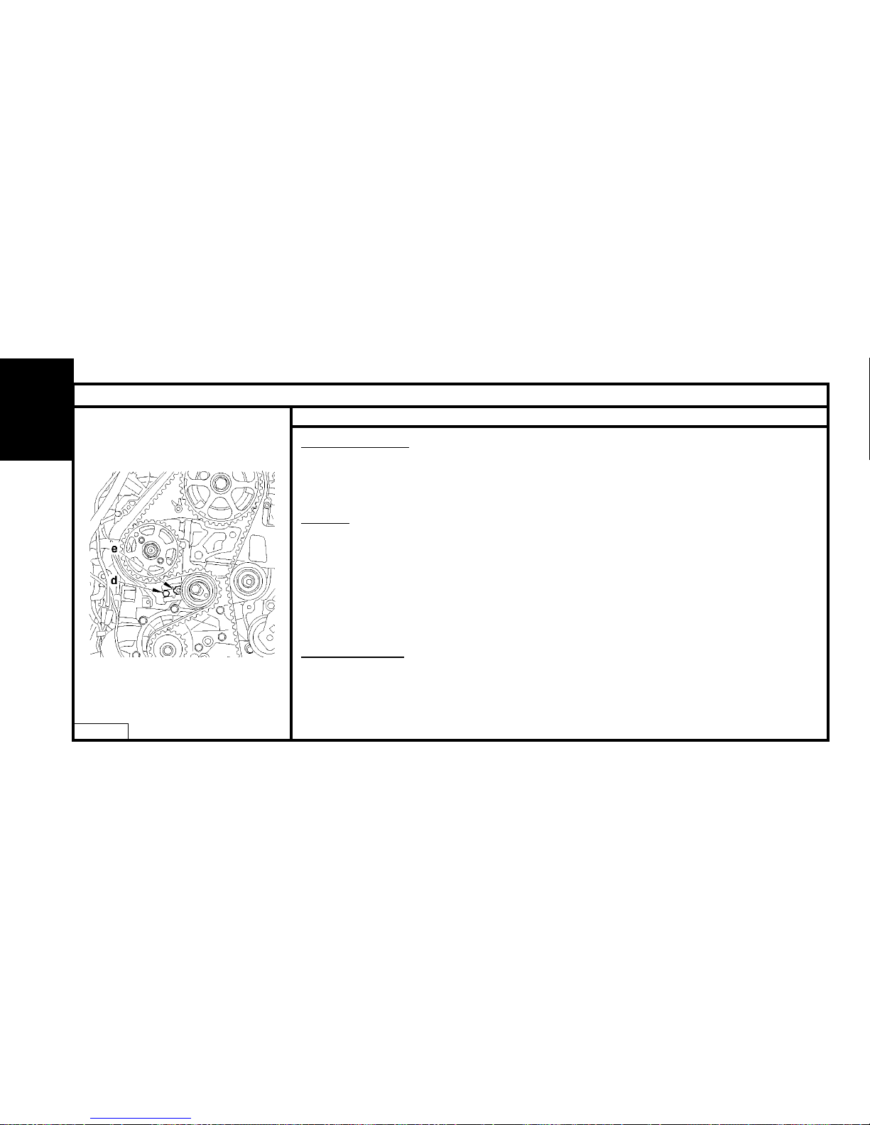
NOTE : The index «e» of the dynamic tensioner roller should be centred within the area «d».
Check the correct positioning of the index «e».
If it is not correct, repeat the operation to tension the timing belt (see corresponding operation).
Refitting.
Refit the tool [1] at «a».
Remove the screw (8).
Refit:
- The upper timing cover (11).
- The lower timing cover (10).
- The accessories drive pulley (9).
- The screw (8).
Tightening torque:
- Screw (8) :
Pre-tighten to : 3 ± 0,3 m.daN.
Angular tightening : 180° ± 5°.
Remove the tool [1].
ENGINE
Page 83
81
CHECKING AND SETTING THE VALVE TIMING
Engines : 8HY - 8HV
B1BP2N0C
Checks (continued).
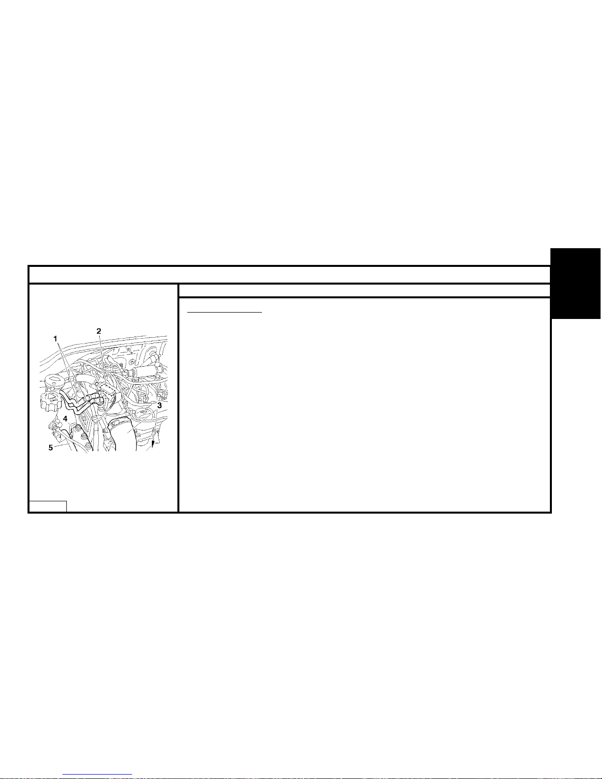
Refit :
- The engine support (7), tighten to 1,5 ± 0.4 m.daN.
- The engine support (4), tighten to 6,1 ± 0,. m.daN.
- The engine support (5), tighten to 6 ± 0.6 m.daN.
- The electrical harness (6).
Couple:
- The exhaust line, tighten the collar to : 2.5 ± 0.3 m daN
- The fuel supply unions (1).
- The air/air heat exchanger inlet/outlet pipes (3).
Connect the connector (2).
Refit :
- The accessories belt (see corresponding operation).
- The front RH splash-shield (see corresponding operation).
- The front RH road wheel, tighten to 9 ± 1 m.daN.
Reconnect the battery.
ENGINE
Page 84
82
CHECKING AND SETTING THE VALVE TIMING
Engines : 8HY - 8HV
B1EP18VD
Setting the timing.
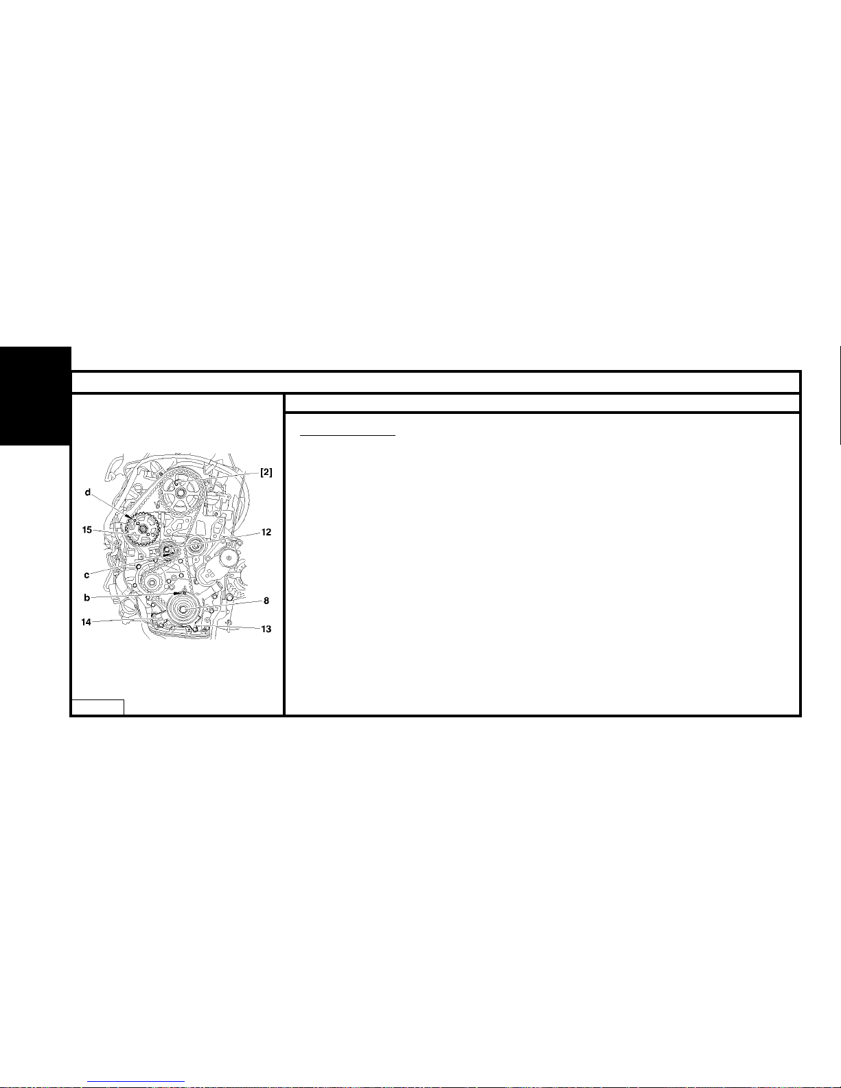
Perform the preliminary operations for checking the timing up to removing tool [1] at «a» for
immobiling the engine flywheel.
Refit screw (8).
Rotate the crankshaft to bring the camshaft towards its pegging point.
Peg the camshaft, using tool [2]. (Oil the pegs).
WARNING: Do not press or damage the track which is the target for the engine speed sensor (14).
Peg the crankshaft at «b», using tool [3].
Remove:
- The timing protector (13).
- The engine speed sensor (14).
Slacken the screw (12) of the tensioner roller, keeping it slack with t he aid of a hexagonal spanner
at «c».
Detension the belt by pivoting the tensioner roller (clockwise).
Remove the timing belt, commencing with the coolant pump pinion.
Peg the pulley (15), using a 5 mm diameter peg at «d».
ENGINE
Page 85
83
CHECKING AND SETTING THE VALVE TIMING
Engines : 8HY - 8HV
B1EP18WD
Setting the timing (continued).
Checking the setting.
IMPERATIVE : Just prior to refitting, carry out the following tests:
Check that:
- the rollers and the coolant pump operate freely
(no play and no tight spot).
- there are no traces of oil
(from the crankshaft and camshaft sealing rings).
- there is no leak of coolant fluid (from the coolant pump).
- the target track of the engine speed sensor (14) is not damaged or scratched.
(If necessary replace the defective components).
Refitting
Fit the timing belt on the crankshaft pinion.
Position the belt on the guide roller, with the belt well tensioned.
Refit:
- The timing protector (13).
- The sensor (14).
ENGINE
Page 86
84
CHECKING AND SETTING THE VALVE TIMING
Engines : 8HY - 8HV
B1EP18XC
Setting the timing (continued).
Checks (continued).
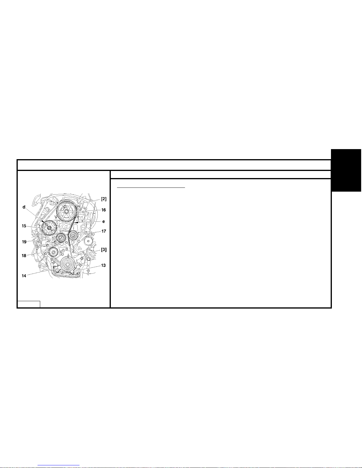
Reposition the timing belt, belt at «e» well tensioned, in the following order:
- Guide roller (17).
- Camshaft pulley (16).
- Fuel high pressure pump pulley (15).
- Coolant pump pinion (18).
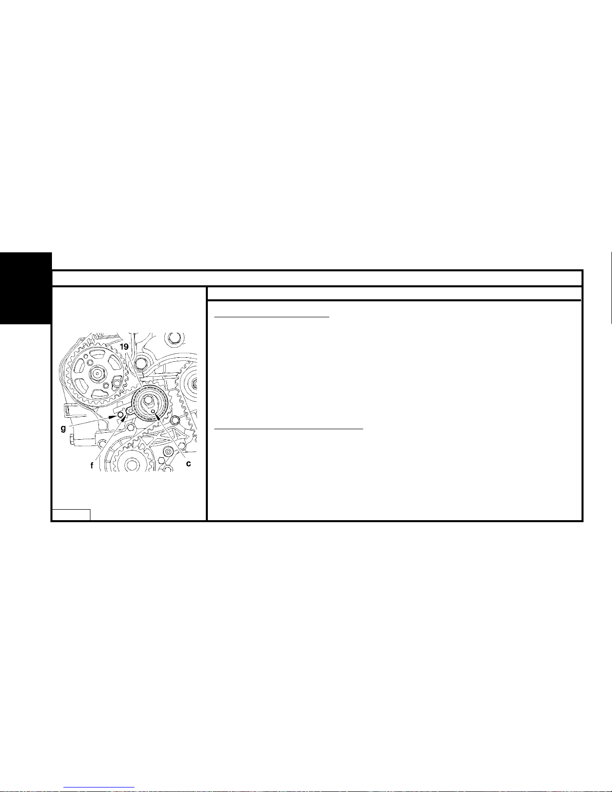
- Tensioner roller (19).
Remove the 5 mm diameter peg at «d».
Adjusting the fitting tension of the belt.
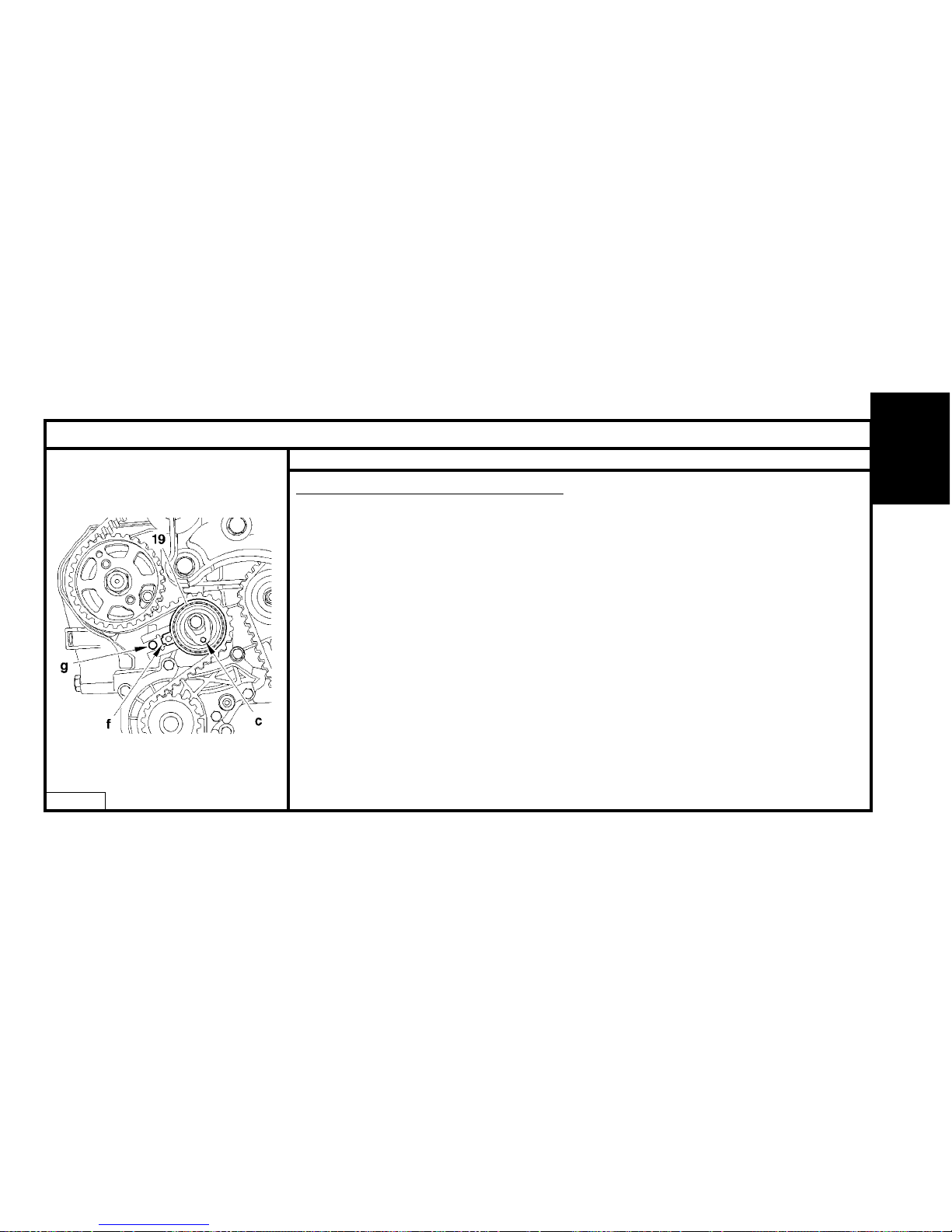
Action the tensioner roller (19) to align the marks «f» and «g» , avoiding detensioning the timing belt,
with the aid of a male hexagonal spanner, at «c».
If this is not successful, repeat the operation to tension the belt.
Hold the tensioner roller in position (19).
Tighten the tensioner roller, tightening to 3,7 ± 0,3 m.daN.
Check the position of the tensioner roller (the alignment of the marks «f» and «g» should be correct).
Remove tools [2] and [3].
Turn the crankshaft six rotations (clockwise).
ENGINE
Page 87
85
CHECKING AND SETTING THE VALVE TIMING
Engines : 8HY - 8HV
B1EP18XC
Adjusting the timing belt tension (continued).
IMPERATIVE : Never rotate the engine backwards.
WARNING : Do not touch or damage the track of the target of the engine speed sensor(14).
Peg the crankshaft, using tool [3].
Check the position of the tensioner roller (the alignment of the marks «f» and «g» should
be correct).
If this is not the case, repeat the operation to tension the belt.
Peg the camshaft pulley, using tool [2].
IMPERATIVE : Should it be impossible to peg the camshaft, check that the offset between the camshaft hole and the pegging hole is not more than 1 mm. If the offset is
too great, repeat the operation.
Remove the pegs [2] and [3].
Refit tool [1] at «a».
Remove the screw (8).
Complete the refitting.
ENGINE
Page 88
86
SPECIAL FEATURES : POWER UNIT SUSPENSION
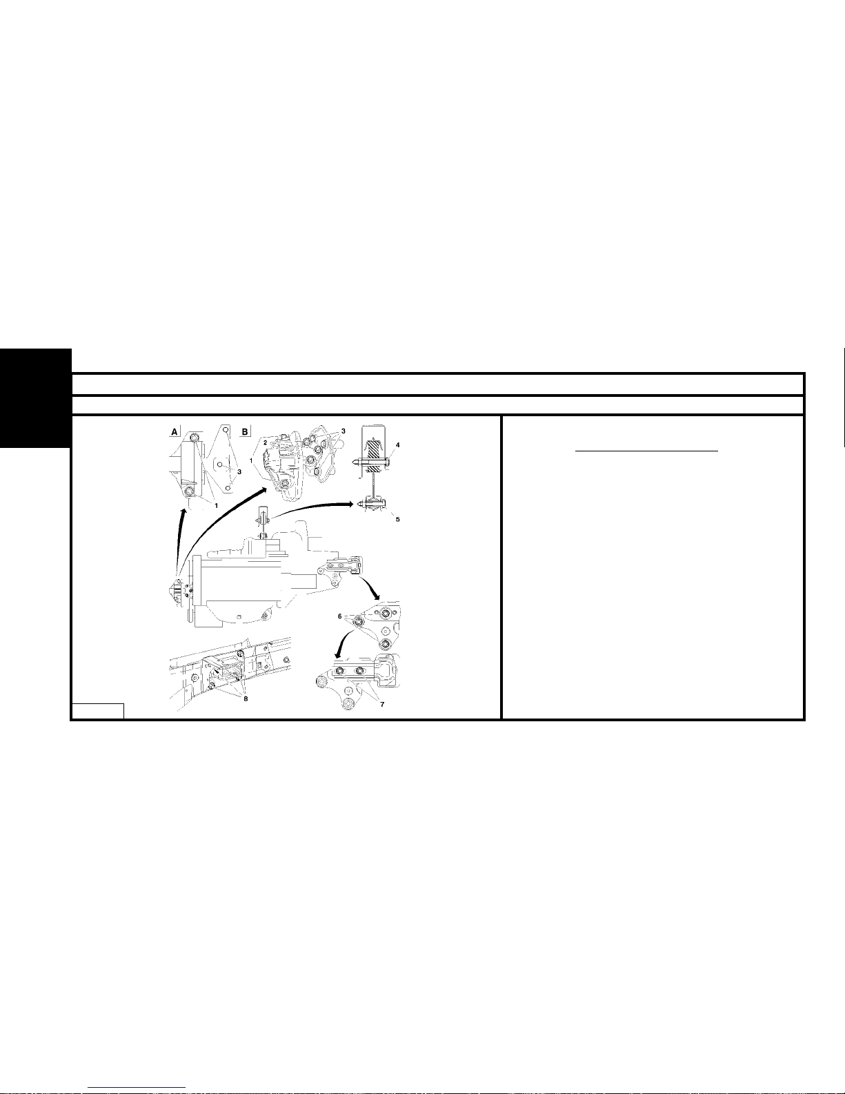
Engines : HFX - KFV - NFU
T
ightening torques (m.daN)
RH engine support.
(1) : 4.5 ± 0.4
(2) : 6.1 ± 0.6
(3) : 4.5 ± 0.4
Torque reaction rod.
(4) : 6 ± 0.6
(5) : 6 ± 0.6
LH engine support.
(6) : 3 ± 0.3
(7) : 6 ± 0.6
(8) : 5.5 ± 0.5
ENGINE
B1BP2NEP
Page 89
87
SPECIAL FEATURES : POWER UNIT SUSPENSION
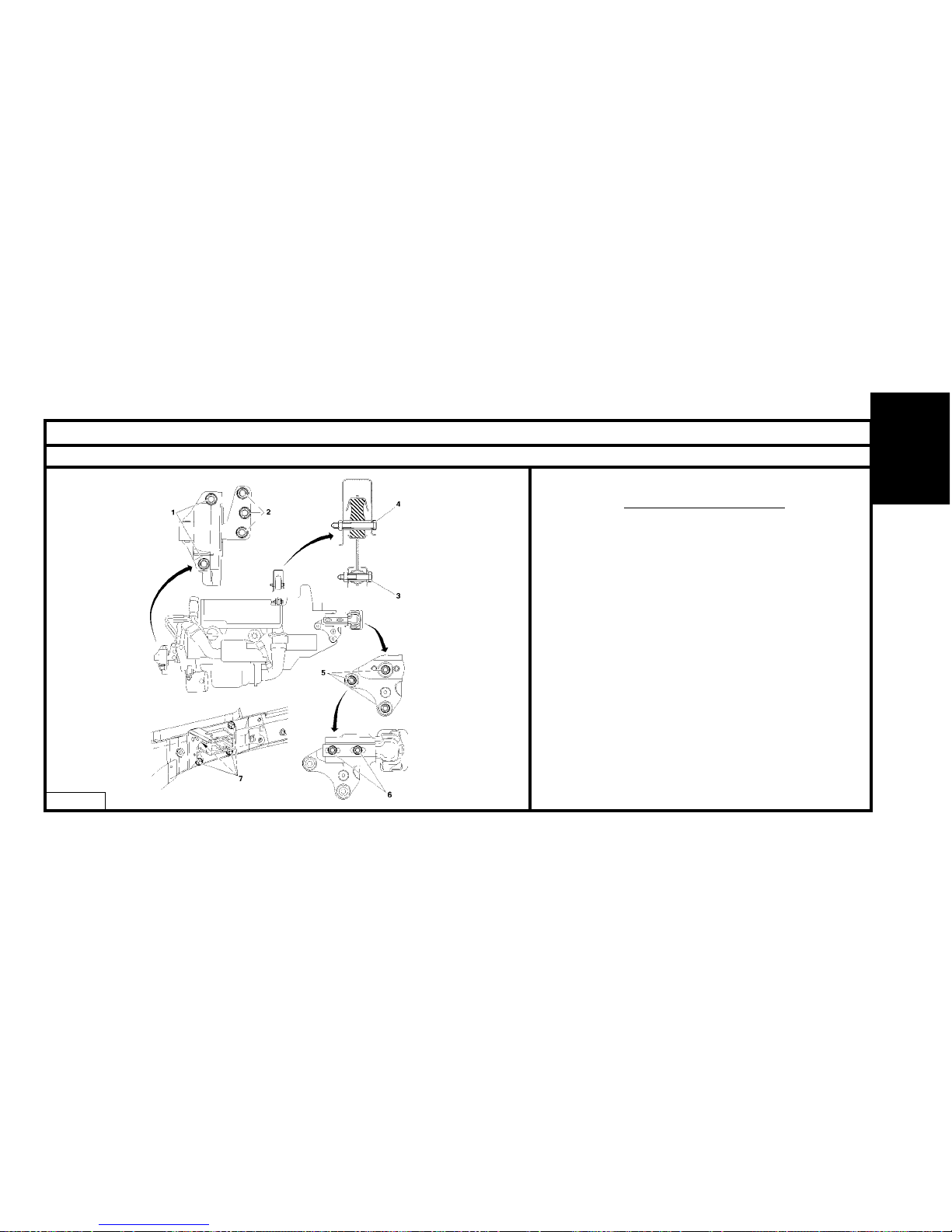
Engines : 8HX - 8HW
T
ightening torques (m.daN)
RH engine support.
(1) : 4,5 ± 0,4
(2) : 3 ± 0,3
Torque reaction rod.
(3) : 6 ± 0.6
(4) : 6 ± 0.6
LH engine support.
(5) : 5.4 ± 0.5
(6) : 6 ± 0.6
(7) : 5.5 ± 0.5
ENGINE
B1BP2LJP
Page 90
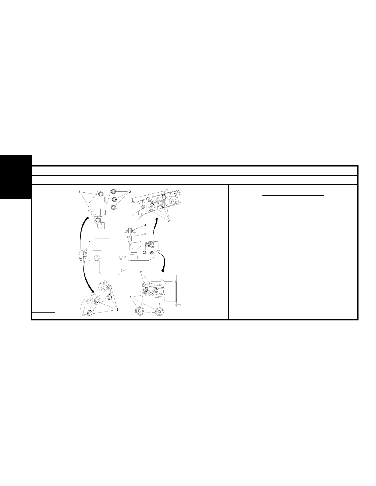
88
SPECIAL FEATURES : POWER UNIT SUSPENSION
Engines : 8HY - 8HV
T
ightening torques m.daN.
Upper RH engine support.
(1) Screws : 6 ± 0.6
(2) Screws : 6 ± 0.6
Lower RH engine support.
(3) Screws : 5.7 ± 0.9
Torque reaction rod.
(4) Screws : 6 ± 0.6
(5) Screws : 6 ± 0.6
Lower LH engine support.
(6) Screws : 5.4 ± 0.5
Upper LH engine support.
(7) Screws : 6 ± 0.6
(8) Screws : 5.5 ± 0.5
B1BP2MNP
ENGINE
Page 91
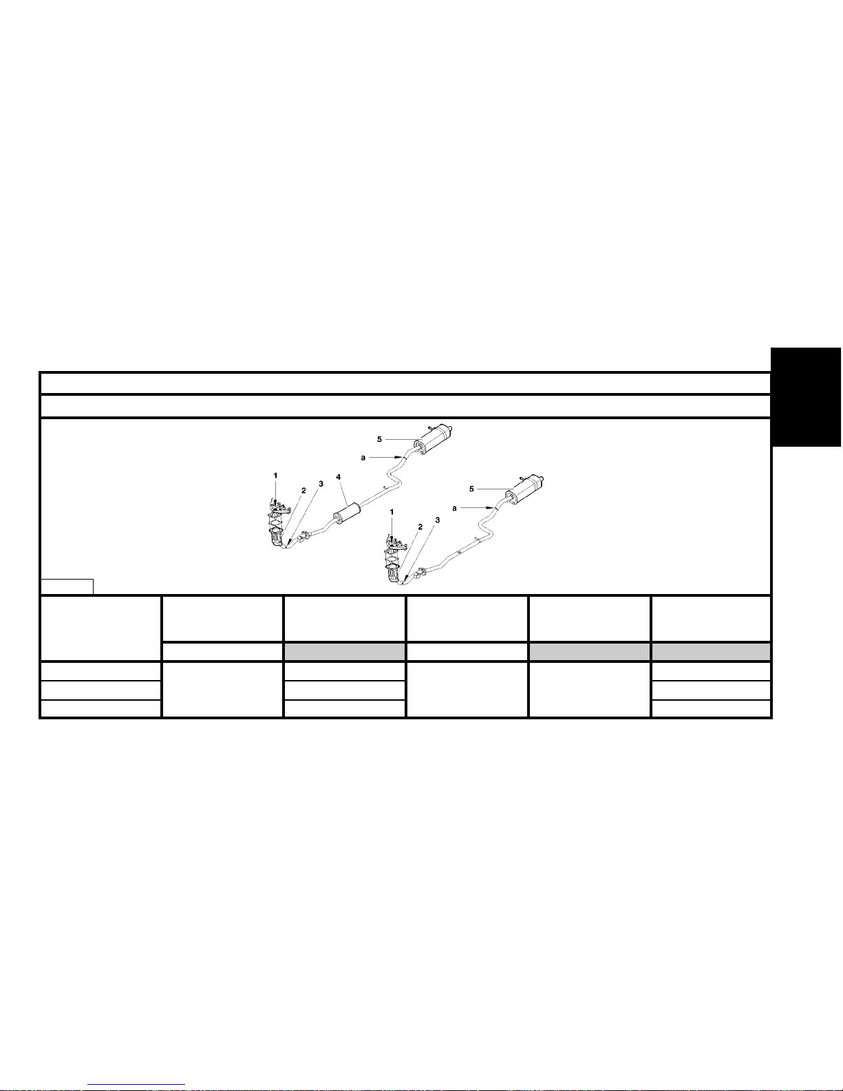
89
EXHAUST SPECIFICATIONS
Engines : HFX - KFV - NFU
HFX TR PSA K179 PSA 4173
KFV 4,7 ± 0.5 TR PSA K208 4.7 ± 0.5 PSA 4175 PSA 4174
NFU TR PSA K181 PSA 4176
Engine types
(1)
Upstream oxygen
sensor
Tighten to (m.daN)
(2)
Catalytic converter
(3)
Downstream oxygen
sensor
Tighten to (m.daN)
(4)
Front silencer
(5)
Rear silencer
ENGINE
B1JP03TD
Page 92
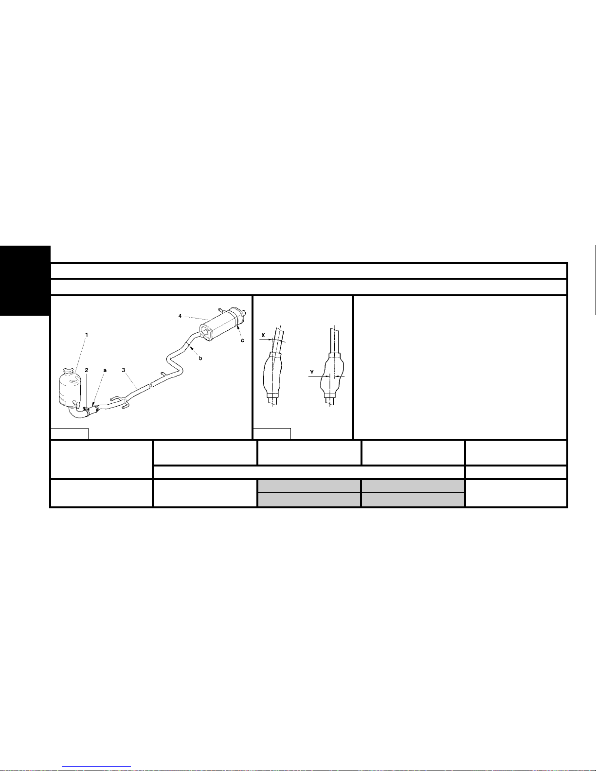
90
EXHAUST SPECIFICATIONS
Engines : 8HX - 8HW
8HX - 8HW TR PSA K213
Engine types
(1)
Catalytic converter
(2)
Clip
(3)
Intermediate pipe
(4)
Rear silencer
Tighten to 2,5 ± 0,3
Tighten to 1,5 ± 0,1
PSA 4177
ENGINE
Repair
Respect the precautions to be taken when operating on a
vehicle.
The flexible pipe must not come into contact with corrosive products.
Do not distort the flexible pipe by more than 20° angular
(X), 20 mmaxial, 25 mm shear (Y) (flexible pipe not fitted).
Do not distort the flexible pipe by more than 3° angular (X),
0 mm axial, 3 mm shear (Y) (flexible pipe in place).
WARNING : Non-respect for these precautions will result
in a reduction in the lifetime of the flexible pipe. It is thus
essential to disconnect or remove the exhaust line in any
operation necessitating the lifting of the power unit.
B1JP03PD B1JP02JC
Page 93
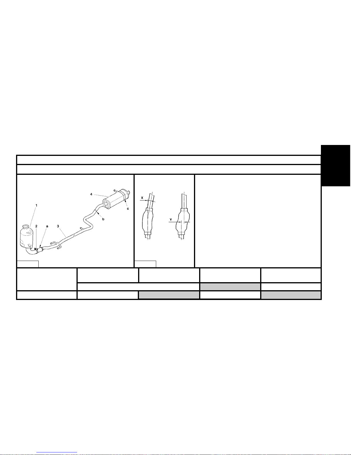
91
EXHAUST SPECIFICATIONS
Engines : 8HY – 8HV
Flexible pipe
Respect the precautions to be taken when operating on a
vehicle.
The flexible pipe must not come into contact with corrosive
products.
Do not distort the flexible pipe by more than 20°angular (X),
20 mm axial, 25 mm shear (Y) (flexible pipe not fitted).
Do not distort the flexible pipe by more than 3° angular (X),
0 mm axial, 3 mm shear (Y) (flexible pipe in place).
WARNING : Non-respect for these precautions will result in
a reduction in the lifetime of the flexible pipe. It is thus
essential to disconnect or remove the exhaust line in any
operation necessitating the lifting of the power unit.
ENGINE
«a» : Cutting zone (Marked by burrs).
B1JP03ND B1JP02JC
8HY–8HV
TR PSA K213
Engine types
(1)
Catalytic converter
(4)
Clip
(2)
Intermediate pipe
(3)
Rear silencer
Tighten to 2,5 ± 0,3
Tighten to 2,5 ± 0,3
PSA 4177-PSA 4179
Page 94
92
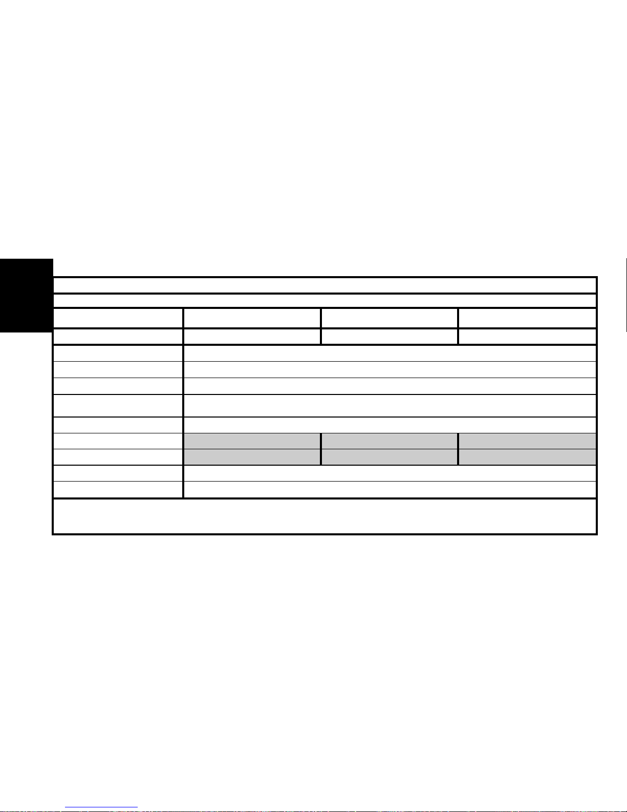
HFX KFV NFU
7
12 and 16 dm
3
1,4 bars
89°C/101°C
100W (without aircon) 300W (with aircon)
118°C
Managed by the ECU
COOLING SYSTEM SPECIFICATIONS
Engines : HFX - KFV - NFU
Engine type
Capacity
Radiator surface
Pressurisation
Opening of thermostatic
regulator
Cooling fan
1st speed
2nd speed
Warning
Post-cooling
1.1i 1.4i 1.6i 16V
ENGINE
Page 95
93
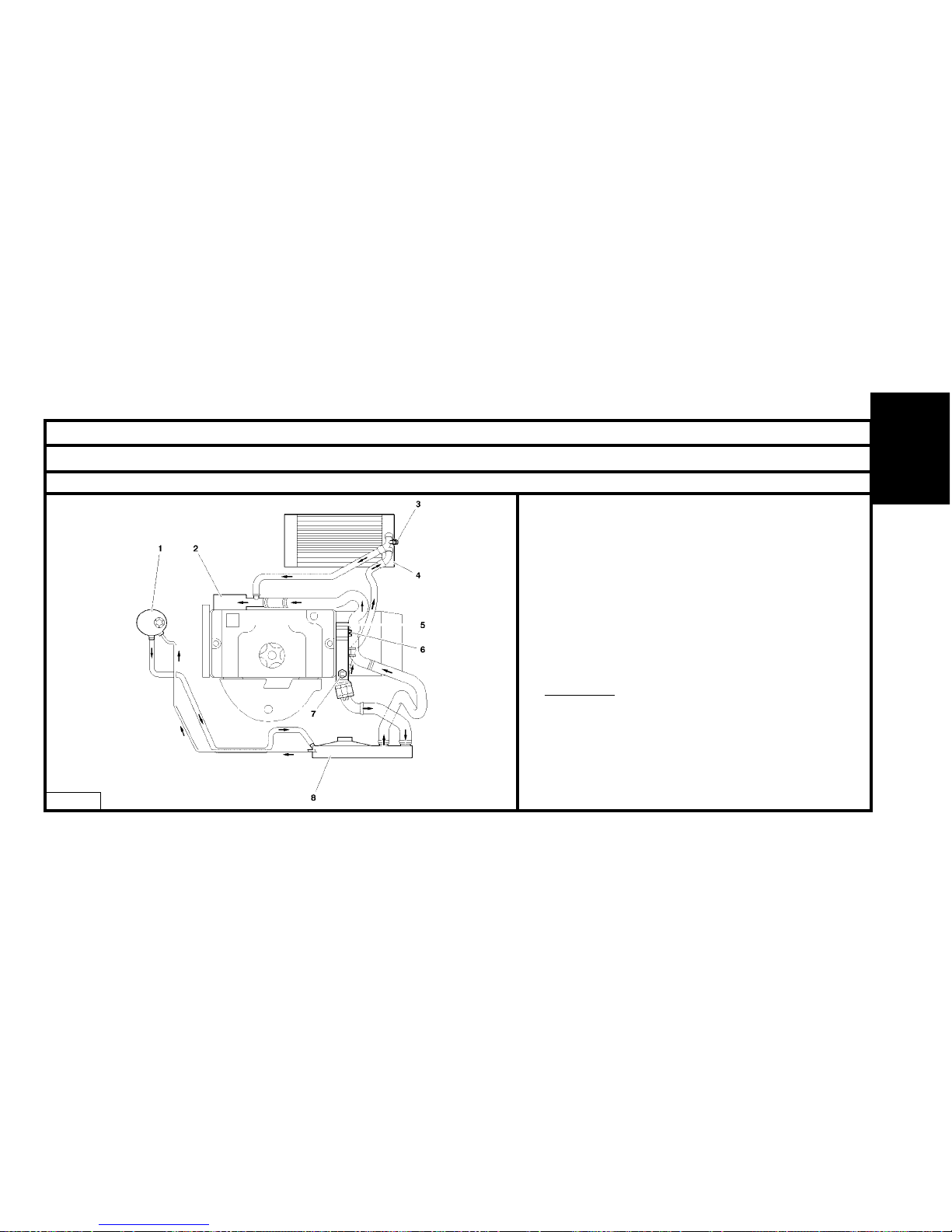
COOLING SYSTEM SPECIFICATIONS
Engines : HFX - KFV - NFU
Manual gearbox.
(1) Venting chamber.
(2) Water pump.
(3) Heater matrix.
(4) Bleed screw, heater matrix
(5) Coolant outlet housing
(6) Bleed screw, coolant outlet housing.
(7) Calorstat.
(8) Cooling radiator.
Thermostat.
Colour of connector : Blue.
Colour of seal : Yellow.
Tightening torque : 1.7 ± 0.2 m.daN.
B1GP09HP
ENGINE
Page 96
94
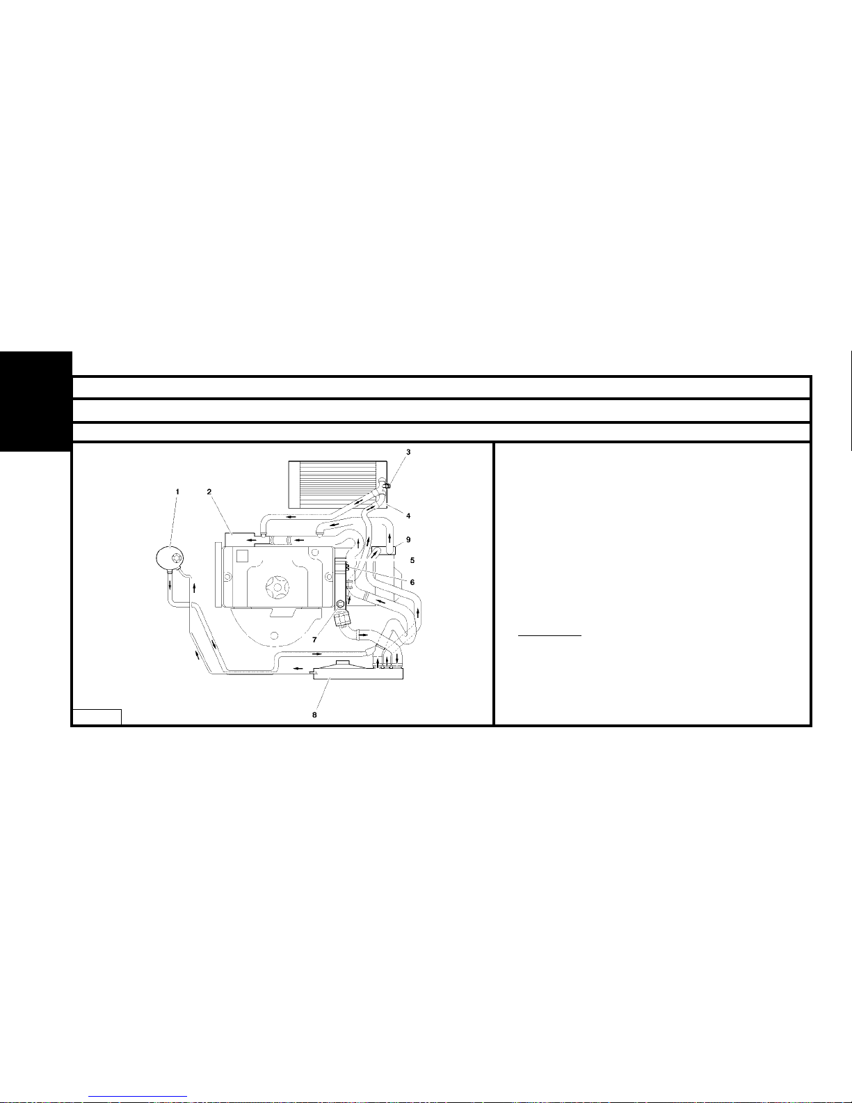
COOLING SYSTEM SPECIFICATIONS
Engines : HFX – KFV – NFU
Automatic gearbox
(1) Venting chamber.
(2) Water pump.
(3) Heater matrix.
(4) Bleed screw, heater matrix
(5) Coolant outlet housing
(6) Bleed screw, coolant outlet housing.
(7) Calorstat.
(8) Cooling radiator.
(9) Heat exchanger (for automatic gearbox).
Thermostat.
Colour of connector : Blue.
Colour of seal : Yellow.
Tightening torque : 1.7 ± 0.2 m.daN.
B1GP09JP
ENGINE
Page 97
95
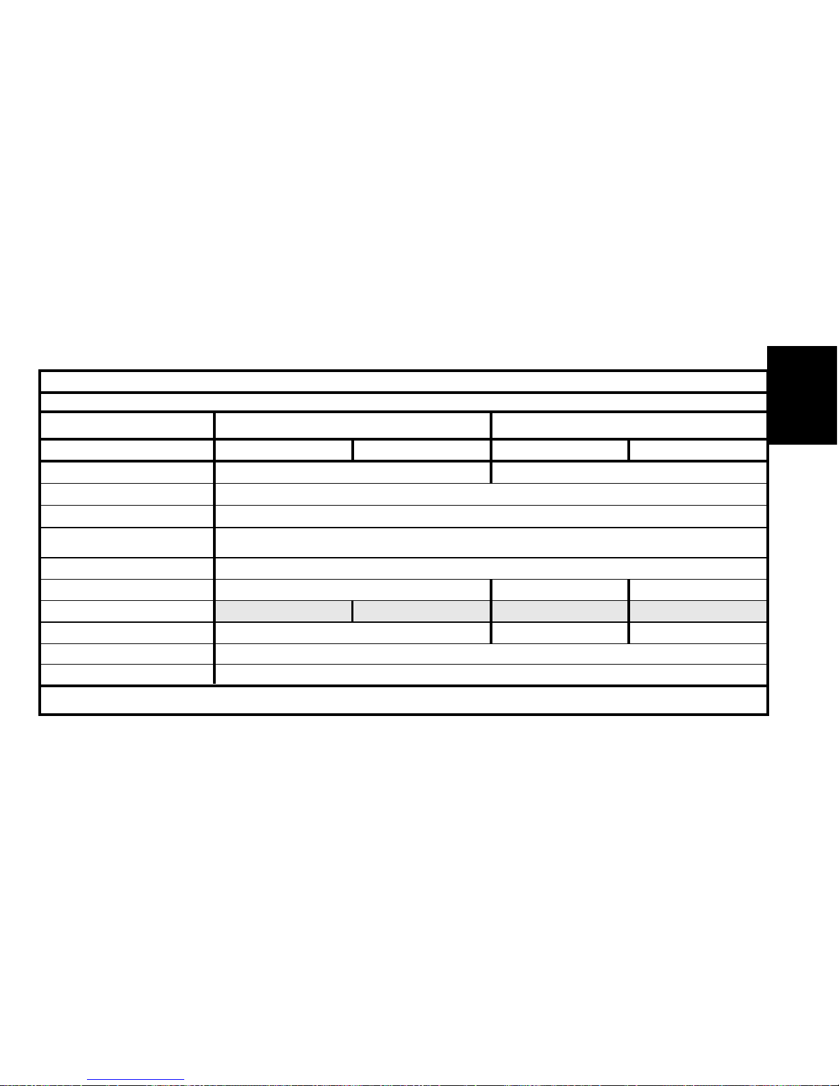
8HX 8HW 8HY 8HV
5.7 Litres 5.6 Litres
16 dm
3
1.4 bar
83°C
1x300W
97°C
115°C
118°C
105°C 6 minutes
COOLING SYSTEM SPECIFICATIONS
Engines : 8HX - 8HW - 8HY - 8HV
Engine type
Capacity
Radiator surface
Pressurisation
Opening of thermostatic
regulator
Cooling fan
1st speed
2nd speed
Air conditioning cut-off
Warning
Post-cooling
1.4 HDi 1.4 HDi 16V
ENGINE
Thermostat : Tightening torque 1.7 ± 0.4 m.daN.
Page 98
96
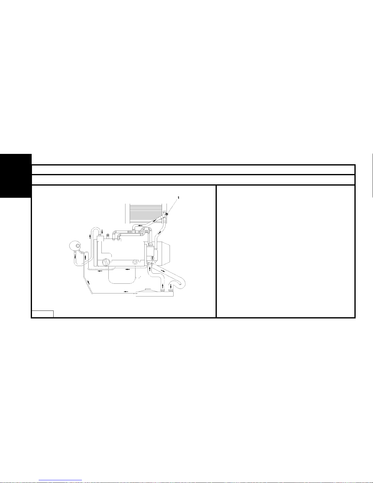
COOLING SYSTEM SPECIFICATIONS
Engines : 8HX - 8HW
(1) Bleed screw (with or without aircon)
B1GP09MP
ENGINE
Page 99
97
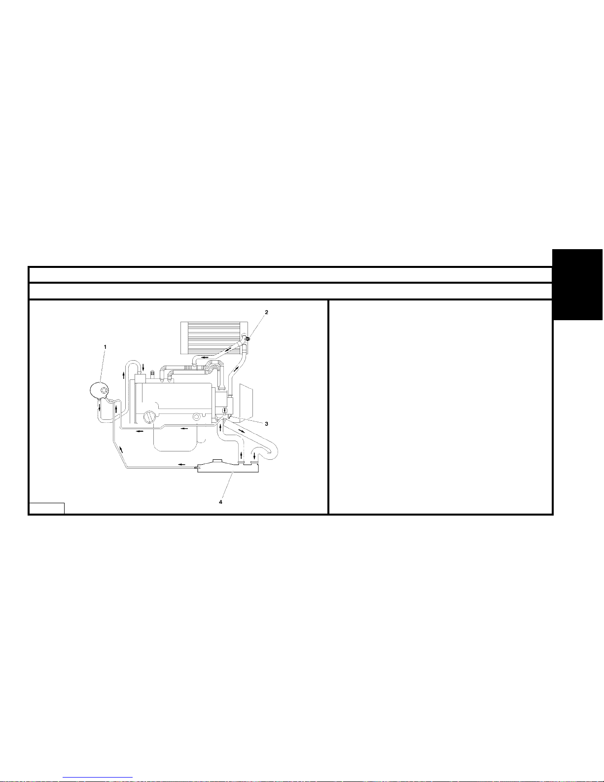
COOLING SYSTEM SPECIFICATIONS
Engines : 8HY - 8HV
(1) Venting chamber.
(2) Bleed screw.
(3) Thermostat.
B1GP09QP
ENGINE
Page 100
Petrol
Diesel
98
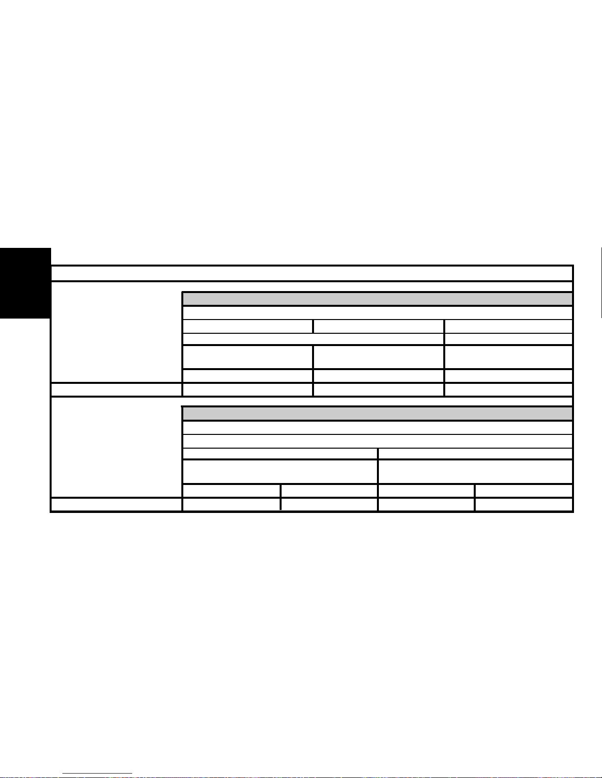
OIL FILTERS
ENGINE
TU
1
JP
1.1i
HFX KFV NFU
XFILTRAUTO X X
1.4i 1.6i 16V
35
JP4
DV
TD
1.4 HDi
8HX 8HW 8HV 8HY
XMALHEX X X X
1.4 HDi 16V
4
TED4
 Loading...