

Cisco CVPN3002-8E-K9 - Fast Ethernet VPN Gateway, 3002 - VPN Hardware Client, VPN 3002 Hardware Client Manager User Manual
Page 1

170 West Tasman Drive
San Jose, CA 95134-1706
USA
http://www.cisco.com
Cisco Systems, Inc.
Corporate Headquarters
Tel:
800 553-NETS (6387)
408 526-4000
Fax: 408 526-4100
VPN 3002 Hardware Client
User Guide
Release 3.0
March 2001
Customer Order Number: OL-0874-=
Text Part Number: OL-0874-01
Page 2

THE SPECIFICATIONS AND INFORMATION REGARDING THE PRODUCTS IN THIS MANUAL ARE SUBJECT TO CHANGE WITHOUT
NOTICE. ALL STATEMENTS, INFORMATION, AND RECOMMENDATIONS IN THIS MANUAL ARE BELIEVED TO BE ACCURATE BUT ARE
PRESENTED WITHOUT WARRANTY OF ANY KIND, EXPRESS OR IMPLIED. USERS MUST TAKE FULL RESPONSIBILITY FOR THEIR
APPLICATION OF ANY PRODUCTS.
THE SOFTWARE LICENSE AND LIMITED WARRANTY FOR THE ACCOMPANYING PRODUCT ARE SET FORTH IN THE INFORMATION
PACKET THAT SHIPPED WITH THE PRODUCT AND ARE INCORPORATED HEREIN BY THIS REFERENCE. IF YOU ARE UNABLE TO
LOCATE THE SOFTWARE LICENSE OR LIMITED WARRANTY, CONTACT YOUR CISCO REPRESENTATIVE FOR A COPY.
The Cisco implementation of TCP header compression is an adaptation of a program developed by the University of California, Berkeley (UCB) as part of
UCB’s public domain version of the UNIX operating system. All rights reserved. Copyright © 1981, Regents of the University of California.
NOTWITHSTANDING ANY OTHER WARRANTY HEREIN, ALL DOCUMENT FILES AND SOFTWARE OF THESE SUPPLIERS ARE PROVIDED
“AS IS” WITH ALL FAULTS. CISCO AND THE ABOVE-NAMED SUPPLIERS DISCLAIM ALL WARRANTIES, EXPRESSED OR IMPLIED,
INCLUDING, WITHOUT LIMITATION, THOSE OF MERCHANTABILITY, FITNESS FOR A PARTICULAR PURPOSE AND
NONINFRINGEMENT OR ARISING FROM A COURSE OF DEALING, USAGE, OR TRADE PRACTICE.
IN NO EVENT SHALL CISCO OR ITS SUPPLIERS BE LIABLE FOR ANY INDIRECT, SPECIAL, CONSEQUENTIAL, OR INCIDENTAL
DAMAGES, INCLUDING, WITHOUT LIMITATION, LOST PROFITS OR LOSS OR DAMAGE TO DATA ARISING OUT OF THE USE OR
INABILITY TO USE THIS MANUAL, EVEN IF CISCO OR ITS SUPPLIERS HAVE BEEN ADVISED OF THE POSSIBILITY OF SUCH DAMAGES.
AccessPath, AtmDirector, Browse with Me, CCDA, CCDE, CCDP, CCIE, CCNA, CCNP, CCSI, CD-PAC, CiscoLink, the Cisco NetWorks logo, the Cisco
Powered Network logo, Cisco Systems Networking Academy, the Cisco Systems Networking Academy logo, Discover AA That’s Possible, Fast Step,
Follow Me Browsing, FormShare, FrameShare, GigaStack, IGX, Internet Quotient, IP/VC, iQ Breakthrough, iQ Expertise, iQ FastTrack, the iQ Logo, iQ
Net Readiness Scorecard, MGX, the Networkers logo, Packet, PIX, RateMUX, ScriptBuilder, ScriptShare, SlideCast, SMARTnet, TransPath, Voice LAN,
Wavelength Router, WebViewer are trademarks of Cisco Systems, Inc.; Changing the Way We Work, Live, Play, and Learn, Empowering the Internet
Generation, are service marks of Cisco Systems, Inc.; and Aironet, ASIST, BPX, Catalyst, Cisco, the Cisco Certified Internetwork Expert logo, Cisco IOS,
the Cisco IOS logo, Cisco Systems, Cisco Systems Capital, the Cisco Systems logo, Enterprise/Solver, EtherChannel, EtherSwitch, FastHub, FastSwitch,
IOS, IP/TV, LightStream, MICA, Network Registrar, Post-Routing, Pre-Routing, Registrar, StrataView Plus, Stratm, SwitchProbe, TeleRouter, and VCO
are registered trademarks of Cisco Systems, Inc. or its affiliates in the U.S. and certain other countries.
All other brands, names, or trademarks mentioned in this document or Web site are the property of their respective owners. The use of the word partner
does not imply a partnership relationship between Cisco and any other company. (0011R)
VPN 3002 Hardware Client User Guide
Copyright © 2001, Cisco Systems, Inc.
All rights reserved.
Page 3

iii
VPN 3002 Hardware Client User Guide
CONTENTS
Table of contents
Table of contents
Preface
About this manual . . . . . . . . . . . . . . . . . . . . . . . . . . . . . . . . . . . . . . . . . . . . . . . . . . . . . . . . . . . . . . . . . . . . . . . . . . . . . . xi
Additional documentation . . . . . . . . . . . . . . . . . . . . . . . . . . . . . . . . . . . . . . . . . . . . . . . . . . . . . . . . . . . . . . . . . . . . . . xii
Documentation on VPN software distribution CDs . . . . . . . . . . . . . . . . . . . . . . . . . . . . . . . . . . . . . . . . . . . . . . . . xiii
Obtaining documentation . . . . . . . . . . . . . . . . . . . . . . . . . . . . . . . . . . . . . . . . . . . . . . . . . . . . . . . . . . . . . . . . . . . . . . xiii
Obtaining technical assistance . . . . . . . . . . . . . . . . . . . . . . . . . . . . . . . . . . . . . . . . . . . . . . . . . . . . . . . . . . . . . . . . . xiv
Other references . . . . . . . . . . . . . . . . . . . . . . . . . . . . . . . . . . . . . . . . . . . . . . . . . . . . . . . . . . . . . . . . . . . . . . . . . . . . . . xv
Documentation conventions . . . . . . . . . . . . . . . . . . . . . . . . . . . . . . . . . . . . . . . . . . . . . . . . . . . . . . . . . . . . . . . . . . . . xvi
Data formats . . . . . . . . . . . . . . . . . . . . . . . . . . . . . . . . . . . . . . . . . . . . . . . . . . . . . . . . . . . . . . . . . . . . . . . . . . . . . . . . . . xvi
1 Using the VPN 3002 Hardware Client Manager
Browser requirements . . . . . . . . . . . . . . . . . . . . . . . . . . . . . . . . . . . . . . . . . . . . . . . . . . . . . . . . . . . . . . . . . . . . . . . . . 1-1
Recommended PC monitor / display settings . . . . . . . . . . . . . . . . . . . . . . . . . . . . . . . . . . . . . . . . . . . . . . . . . . . . . . 1-3
Connecting to the VPN 3002 using HTTP . . . . . . . . . . . . . . . . . . . . . . . . . . . . . . . . . . . . . . . . . . . . . . . . . . . . . . . . . . 1-3
Installing the SSL certificate in your browser . . . . . . . . . . . . . . . . . . . . . . . . . . . . . . . . . . . . . . . . . . . . . . . . . . . . . 1-3
Connecting to the VPN 3002 using HTTPS . . . . . . . . . . . . . . . . . . . . . . . . . . . . . . . . . . . . . . . . . . . . . . . . . . . . . . . 1-16
Logging in the VPN 3002 Hardware Client Manager . . . . . . . . . . . . . . . . . . . . . . . . . . . . . . . . . . . . . . . . . . . . . . 1-17
Configuring HTTP, HTTPS, and SSL parameters . . . . . . . . . . . . . . . . . . . . . . . . . . . . . . . . . . . . . . . . . . . . . . . . . . 1-18
Understanding the VPN 3002 Hardware Client Manager window . . . . . . . . . . . . . . . . . . . . . . . . . . . . . . . . . . 1-19
Organization of the VPN 3002 Hardware Client Manager . . . . . . . . . . . . . . . . . . . . . . . . . . . . . . . . . . . . . . . . . . 1-22
Navigating the VPN 3002 Hardware Client Manager . . . . . . . . . . . . . . . . . . . . . . . . . . . . . . . . . . . . . . . . . . . . . . 1-23
2 Configuration
Configuration . . . . . . . . . . . . . . . . . . . . . . . . . . . . . . . . . . . . . . . . . . . . . . . . . . . . . . . . . . . . . . . . . . . . . . . . . . . . . . . . . 2-1
3 Interfaces
Configuration | Interfaces . . . . . . . . . . . . . . . . . . . . . . . . . . . . . . . . . . . . . . . . . . . . . . . . . . . . . . . . . . . . . . . . . . . . . . 3-1
Configuration | Interfaces | Private . . . . . . . . . . . . . . . . . . . . . . . . . . . . . . . . . . . . . . . . . . . . . . . . . . . . . . . . . . . . . . 3-3
Configuration | Interfaces | Public . . . . . . . . . . . . . . . . . . . . . . . . . . . . . . . . . . . . . . . . . . . . . . . . . . . . . . . . . . . . . . . 3-5
4 System Configuration
Configuration | System . . . . . . . . . . . . . . . . . . . . . . . . . . . . . . . . . . . . . . . . . . . . . . . . . . . . . . . . . . . . . . . . . . . . . . . . . 4-1
Page 4

Contents—Table of contents
iv
VPN 3002 Hardware Client User Guide
5Servers
Configuration | System | Servers . . . . . . . . . . . . . . . . . . . . . . . . . . . . . . . . . . . . . . . . . . . . . . . . . . . . . . . . . . . . . . . 5-1
Configuration | System | Servers | DNS . . . . . . . . . . . . . . . . . . . . . . . . . . . . . . . . . . . . . . . . . . . . . . . . . . . . . . . . . . 5-1
6 Tunneling
Configuration | System | Tunneling Protocols . . . . . . . . . . . . . . . . . . . . . . . . . . . . . . . . . . . . . . . . . . . . . . . . . . . . 6-2
Configuration | System | Tunneling Protocols | IPSec . . . . . . . . . . . . . . . . . . . . . . . . . . . . . . . . . . . . . . . . . . . . . 6-2
7IP Routing
Configuration | System | IP Routing . . . . . . . . . . . . . . . . . . . . . . . . . . . . . . . . . . . . . . . . . . . . . . . . . . . . . . . . . . . . . 7-1
Configuration | System | IP Routing | Static Routes . . . . . . . . . . . . . . . . . . . . . . . . . . . . . . . . . . . . . . . . . . . . . . . 7-2
Configuration | System | IP Routing | Static Routes |
Add or Modify . . . . . . . . . . . . . . . . . . . . . . . . . . . . . . . . . . . . . . . . . . . . . . . . . . . . . . . . . . . . . . . . . . . . . . . . . . . . . . 7-3
Configuration | System | IP Routing | Default Gateways . . . . . . . . . . . . . . . . . . . . . . . . . . . . . . . . . . . . . . . . . . . 7-4
Configuration | System | IP Routing | DHCP . . . . . . . . . . . . . . . . . . . . . . . . . . . . . . . . . . . . . . . . . . . . . . . . . . . . . . 7-5
Configuration | System | IP Routing | DHCP Options . . . . . . . . . . . . . . . . . . . . . . . . . . . . . . . . . . . . . . . . . . . . . . . 7-7
Configuration | System | IP Routing | DHCP Options |
Add or Modify . . . . . . . . . . . . . . . . . . . . . . . . . . . . . . . . . . . . . . . . . . . . . . . . . . . . . . . . . . . . . . . . . . . . . . . . . . . . . . 7-8
8 Management Protocols
Configuration | System | Management Protocols . . . . . . . . . . . . . . . . . . . . . . . . . . . . . . . . . . . . . . . . . . . . . . . . . 8-1
Configuration | System | Management Protocols | HTTP/HTTPS . . . . . . . . . . . . . . . . . . . . . . . . . . . . . . . . . . . . 8-2
Configuration | System | Management Protocols | Telnet . . . . . . . . . . . . . . . . . . . . . . . . . . . . . . . . . . . . . . . . . . 8-4
Configuration | System | Management Protocols | SNMP . . . . . . . . . . . . . . . . . . . . . . . . . . . . . . . . . . . . . . . . . . 8-5
Configuration | System | Management Protocols |
SNMP Communities . . . . . . . . . . . . . . . . . . . . . . . . . . . . . . . . . . . . . . . . . . . . . . . . . . . . . . . . . . . . . . . . . . . . . . . . 8-7
Configuration | System | Management Protocols | SSL . . . . . . . . . . . . . . . . . . . . . . . . . . . . . . . . . . . . . . . . . . . . 8-9
Configuration | System | Management Protocols | SSH . . . . . . . . . . . . . . . . . . . . . . . . . . . . . . . . . . . . . . . . . . . 8-12
9 Events
Event class . . . . . . . . . . . . . . . . . . . . . . . . . . . . . . . . . . . . . . . . . . . . . . . . . . . . . . . . . . . . . . . . . . . . . . . . . . . . . . . . . . 9-1
Event severity level . . . . . . . . . . . . . . . . . . . . . . . . . . . . . . . . . . . . . . . . . . . . . . . . . . . . . . . . . . . . . . . . . . . . . . . . . . . 9-4
Event log . . . . . . . . . . . . . . . . . . . . . . . . . . . . . . . . . . . . . . . . . . . . . . . . . . . . . . . . . . . . . . . . . . . . . . . . . . . . . . . . . . . . 9-5
Configuration | System | Events . . . . . . . . . . . . . . . . . . . . . . . . . . . . . . . . . . . . . . . . . . . . . . . . . . . . . . . . . . . . . . . . 9-6
Configuration | System | Events | General . . . . . . . . . . . . . . . . . . . . . . . . . . . . . . . . . . . . . . . . . . . . . . . . . . . . . . . . 9-6
Configuration | System | Events | Classes . . . . . . . . . . . . . . . . . . . . . . . . . . . . . . . . . . . . . . . . . . . . . . . . . . . . . . . . 9-8
Configuration | System | Events | Classes | Add or Modify . . . . . . . . . . . . . . . . . . . . . . . . . . . . . . . . . . . . . . . . . 9-9
Configuration | System | Events | Trap Destinations . . . . . . . . . . . . . . . . . . . . . . . . . . . . . . . . . . . . . . . . . . . . . . 9-11
Configuration | System | Events | Trap Destinations |
Add or Modify . . . . . . . . . . . . . . . . . . . . . . . . . . . . . . . . . . . . . . . . . . . . . . . . . . . . . . . . . . . . . . . . . . . . . . . . . . . . . 9-12
Configuration | System | Events | Syslog Servers . . . . . . . . . . . . . . . . . . . . . . . . . . . . . . . . . . . . . . . . . . . . . . . . 9-13
Page 5

Contents—Table of contents
v
VPN 3002 Hardware Client User Guide
Configuration | System | Events | Syslog Servers | Add or Modify . . . . . . . . . . . . . . . . . . . . . . . . . . . . . . . . . . . 9-15
10 General
Configuration | System | General . . . . . . . . . . . . . . . . . . . . . . . . . . . . . . . . . . . . . . . . . . . . . . . . . . . . . . . . . . . . . . . 10-1
Configuration | System | General | Identification . . . . . . . . . . . . . . . . . . . . . . . . . . . . . . . . . . . . . . . . . . . . . . . . . 10-2
Configuration | System | General | Time and Date . . . . . . . . . . . . . . . . . . . . . . . . . . . . . . . . . . . . . . . . . . . . . . . . 10-3
11 Policy Management
Client mode/PAT . . . . . . . . . . . . . . . . . . . . . . . . . . . . . . . . . . . . . . . . . . . . . . . . . . . . . . . . . . . . . . . . . . . . . . . . . . . . . 11-1
Network Extension mode . . . . . . . . . . . . . . . . . . . . . . . . . . . . . . . . . . . . . . . . . . . . . . . . . . . . . . . . . . . . . . . . . . . . . . 11-2
Configuration | Policy Management . . . . . . . . . . . . . . . . . . . . . . . . . . . . . . . . . . . . . . . . . . . . . . . . . . . . . . . . . . . . 11-3
Configuration | Policy Management | Traffic Management . . . . . . . . . . . . . . . . . . . . . . . . . . . . . . . . . . . . . . . . 11-3
Configuration | Policy Management | Traffic
Management | PAT . . . . . . . . . . . . . . . . . . . . . . . . . . . . . . . . . . . . . . . . . . . . . . . . . . . . . . . . . . . . . . . . . . . . . . . . . 11-4
Configuration | Policy Management | Traffic Management |
PAT | Enable . . . . . . . . . . . . . . . . . . . . . . . . . . . . . . . . . . . . . . . . . . . . . . . . . . . . . . . . . . . . . . . . . . . . . . . . . . . . . . . 11-4
12 Administration
Administration . . . . . . . . . . . . . . . . . . . . . . . . . . . . . . . . . . . . . . . . . . . . . . . . . . . . . . . . . . . . . . . . . . . . . . . . . . . . . . . 12-1
Administration | Software Update . . . . . . . . . . . . . . . . . . . . . . . . . . . . . . . . . . . . . . . . . . . . . . . . . . . . . . . . . . . . . . 12-2
Administration | System Reboot . . . . . . . . . . . . . . . . . . . . . . . . . . . . . . . . . . . . . . . . . . . . . . . . . . . . . . . . . . . . . . . . 12-5
Administration | Ping . . . . . . . . . . . . . . . . . . . . . . . . . . . . . . . . . . . . . . . . . . . . . . . . . . . . . . . . . . . . . . . . . . . . . . . . . 12-7
Administration | Access Rights . . . . . . . . . . . . . . . . . . . . . . . . . . . . . . . . . . . . . . . . . . . . . . . . . . . . . . . . . . . . . . . . 12-8
Administration | Access Rights | Administrators . . . . . . . . . . . . . . . . . . . . . . . . . . . . . . . . . . . . . . . . . . . . . . . . . 12-9
Administration | Access Rights | Access Settings . . . . . . . . . . . . . . . . . . . . . . . . . . . . . . . . . . . . . . . . . . . . . . . 12-10
Administration | File Management . . . . . . . . . . . . . . . . . . . . . . . . . . . . . . . . . . . . . . . . . . . . . . . . . . . . . . . . . . . . . 12-11
Administration | File Management | View . . . . . . . . . . . . . . . . . . . . . . . . . . . . . . . . . . . . . . . . . . . . . . . . . . . . . . 12-12
Administration | File Management | Swap Config Files . . . . . . . . . . . . . . . . . . . . . . . . . . . . . . . . . . . . . . . . . . . 12-13
Administration | File Management | Config File Upload . . . . . . . . . . . . . . . . . . . . . . . . . . . . . . . . . . . . . . . . . . 12-13
Administration | Certificate Management . . . . . . . . . . . . . . . . . . . . . . . . . . . . . . . . . . . . . . . . . . . . . . . . . . . . . . 12-15
Administration | Certificate Management | Enrollment . . . . . . . . . . . . . . . . . . . . . . . . . . . . . . . . . . . . . . . . . . . 12-17
Administration | Certificate Management | Enrollment |
Request Generated . . . . . . . . . . . . . . . . . . . . . . . . . . . . . . . . . . . . . . . . . . . . . . . . . . . . . . . . . . . . . . . . . . . . . . . . 12-20
Administration | Certificate Management | Installation . . . . . . . . . . . . . . . . . . . . . . . . . . . . . . . . . . . . . . . . . . 12-21
Administration | Certificate Management | Certificates . . . . . . . . . . . . . . . . . . . . . . . . . . . . . . . . . . . . . . . . . . 12-23
Administration | Certificate Management | Certificates | View . . . . . . . . . . . . . . . . . . . . . . . . . . . . . . . . . . . . 12-24
Administration | Certificate Management | Certificates | Delete . . . . . . . . . . . . . . . . . . . . . . . . . . . . . . . . . . . 12-27
13 Monitoring
Monitoring . . . . . . . . . . . . . . . . . . . . . . . . . . . . . . . . . . . . . . . . . . . . . . . . . . . . . . . . . . . . . . . . . . . . . . . . . . . . . . . . . . 13-1
Monitoring | Routing Table . . . . . . . . . . . . . . . . . . . . . . . . . . . . . . . . . . . . . . . . . . . . . . . . . . . . . . . . . . . . . . . . . . . . 13-2
Page 6

Contents—Table of contents
vi
VPN 3002 Hardware Client User Guide
Monitoring | Filterable Event Log . . . . . . . . . . . . . . . . . . . . . . . . . . . . . . . . . . . . . . . . . . . . . . . . . . . . . . . . . . . . . . 13-3
Monitoring | Live Event Log . . . . . . . . . . . . . . . . . . . . . . . . . . . . . . . . . . . . . . . . . . . . . . . . . . . . . . . . . . . . . . . . . . . 13-8
Monitoring | System Status . . . . . . . . . . . . . . . . . . . . . . . . . . . . . . . . . . . . . . . . . . . . . . . . . . . . . . . . . . . . . . . . . . . 13-9
Monitoring | System Status | Private/Public Interface . . . . . . . . . . . . . . . . . . . . . . . . . . . . . . . . . . . . . . . . . . . 13-12
Monitoring | Statistics . . . . . . . . . . . . . . . . . . . . . . . . . . . . . . . . . . . . . . . . . . . . . . . . . . . . . . . . . . . . . . . . . . . . . . 13-14
Monitoring | Statistics | IPSec . . . . . . . . . . . . . . . . . . . . . . . . . . . . . . . . . . . . . . . . . . . . . . . . . . . . . . . . . . . . . . . 13-15
Monitoring | Statistics | HTTP . . . . . . . . . . . . . . . . . . . . . . . . . . . . . . . . . . . . . . . . . . . . . . . . . . . . . . . . . . . . . . . . 13-21
Monitoring | Statistics | Telnet . . . . . . . . . . . . . . . . . . . . . . . . . . . . . . . . . . . . . . . . . . . . . . . . . . . . . . . . . . . . . . . 13-22
Monitoring | Statistics | DNS . . . . . . . . . . . . . . . . . . . . . . . . . . . . . . . . . . . . . . . . . . . . . . . . . . . . . . . . . . . . . . . . . 13-23
Monitoring | Statistics | SSL . . . . . . . . . . . . . . . . . . . . . . . . . . . . . . . . . . . . . . . . . . . . . . . . . . . . . . . . . . . . . . . . . 13-24
Monitoring | Statistics | DHCP . . . . . . . . . . . . . . . . . . . . . . . . . . . . . . . . . . . . . . . . . . . . . . . . . . . . . . . . . . . . . . . 13-26
Monitoring | Statistics | SSH . . . . . . . . . . . . . . . . . . . . . . . . . . . . . . . . . . . . . . . . . . . . . . . . . . . . . . . . . . . . . . . . . 13-27
Monitoring | Statistics | MIB-II . . . . . . . . . . . . . . . . . . . . . . . . . . . . . . . . . . . . . . . . . . . . . . . . . . . . . . . . . . . . . . . 13-28
Monitoring | Statistics | MIB-II | Interfaces . . . . . . . . . . . . . . . . . . . . . . . . . . . . . . . . . . . . . . . . . . . . . . . . . . . . 13-28
Monitoring | Statistics | MIB-II | TCP/UDP . . . . . . . . . . . . . . . . . . . . . . . . . . . . . . . . . . . . . . . . . . . . . . . . . . . . . 13-30
Monitoring | Statistics | MIB-II | IP . . . . . . . . . . . . . . . . . . . . . . . . . . . . . . . . . . . . . . . . . . . . . . . . . . . . . . . . . . . 13-32
Monitoring | Statistics | MIB-II | ICMP . . . . . . . . . . . . . . . . . . . . . . . . . . . . . . . . . . . . . . . . . . . . . . . . . . . . . . . . 13-35
Monitoring | Statistics | MIB-II | ARP Table . . . . . . . . . . . . . . . . . . . . . . . . . . . . . . . . . . . . . . . . . . . . . . . . . . . . 13-37
Monitoring | Statistics | MIB-II | Ethernet . . . . . . . . . . . . . . . . . . . . . . . . . . . . . . . . . . . . . . . . . . . . . . . . . . . . . . 13-39
Monitoring | Statistics | MIB-II | SNMP . . . . . . . . . . . . . . . . . . . . . . . . . . . . . . . . . . . . . . . . . . . . . . . . . . . . . . . 13-41
14 Using the Command Line Interface
Accessing the CLI . . . . . . . . . . . . . . . . . . . . . . . . . . . . . . . . . . . . . . . . . . . . . . . . . . . . . . . . . . . . . . . . . . . . . . . . . . . 14-1
Starting the CLI . . . . . . . . . . . . . . . . . . . . . . . . . . . . . . . . . . . . . . . . . . . . . . . . . . . . . . . . . . . . . . . . . . . . . . . . . . . . . . 14-2
Using the CLI . . . . . . . . . . . . . . . . . . . . . . . . . . . . . . . . . . . . . . . . . . . . . . . . . . . . . . . . . . . . . . . . . . . . . . . . . . . . . . . 14-3
CLI menu reference . . . . . . . . . . . . . . . . . . . . . . . . . . . . . . . . . . . . . . . . . . . . . . . . . . . . . . . . . . . . . . . . . . . . . . . . . 14-7
A Errors and troubleshooting
Files for troubleshooting . . . . . . . . . . . . . . . . . . . . . . . . . . . . . . . . . . . . . . . . . . . . . . . . . . . . . . . . . . . . . . . . . . . . . . A-1
LED indicators . . . . . . . . . . . . . . . . . . . . . . . . . . . . . . . . . . . . . . . . . . . . . . . . . . . . . . . . . . . . . . . . . . . . . . . . . . . . . . . A-2
Errors on the system . . . . . . . . . . . . . . . . . . . . . . . . . . . . . . . . . . . . . . . . . . . . . . . . . . . . . . . . . . . . . . . . . . . . . . . . . . A-3
Settings on the VPN 3000 Series Concentrator . . . . . . . . . . . . . . . . . . . . . . . . . . . . . . . . . . . . . . . . . . . . . . . . . . . A-4
VPN 3002 Hardware Client Manager errors . . . . . . . . . . . . . . . . . . . . . . . . . . . . . . . . . . . . . . . . . . . . . . . . . . . . . . A-5
Command Line Interface errors . . . . . . . . . . . . . . . . . . . . . . . . . . . . . . . . . . . . . . . . . . . . . . . . . . . . . . . . . . . . . . . A-10
B Copyrights, licenses, and notices
Software License Agreement of Cisco Systems, Inc. . . . . . . . . . . . . . . . . . . . . . . . . . . . . . . . . . . . . . . . . . . . . . . B-1
Other licenses . . . . . . . . . . . . . . . . . . . . . . . . . . . . . . . . . . . . . . . . . . . . . . . . . . . . . . . . . . . . . . . . . . . . . . . . . . . . . . . B-3
Regulatory Standards Compliance . . . . . . . . . . . . . . . . . . . . . . . . . . . . . . . . . . . . . . . . . . . . . . . . . . . . . . . . . . . . . . B-9
Page 7

Index
Page 8

Contents—Table of contents
viii
VPN 3002 Hardware Client User Guide
Page 9

Contents
ix
VPN 3002 Hardware Client User Guide
Tables
Table 9-1: VPN 3002 event classes . . . . . . . . . . . . . . . . . . . . . . . . . . . . . . . . . . . . . . . . . . . . . . . . . . . . . . . . . . . . . . . . 9-1
Table 9-2: VPN 3002 event severity levels . . . . . . . . . . . . . . . . . . . . . . . . . . . . . . . . . . . . . . . . . . . . . . . . . . . . . . . . . 9-4
Table 9-3: Configuring “well-known” SNMP traps . . . . . . . . . . . . . . . . . . . . . . . . . . . . . . . . . . . . . . . . . . . . . . . . . 9-7
Page 10

Page 11

xi
VPN 3002 Hardware Client User Guide
Preface
About this manual
The VPN 3002 Hardware Client User Guide provides guidelines for configuring the Cisco VPN 3002,
details on all the functions available in the VPN 3002 Hardware Client Manager, and instructions for
using the VPN 3002 Command Line Interface.
Prerequisites
We assume yo u have read the VPN 3002 Hardware Client Getting Started manual and have followed the
minimal configuration steps in Quick Configuration. That section of the VPN Hardware Client Manager
is not described here.
We also assume you are an experienced system administrator or network administrator with appropriate
education and training, who knows how to install, configure, and manage internetworking systems.
However, virtual private networks and VPN devices may be new to you. You should be familiar with
Windows® 95/98 or Windows NT® system configuration and management, and you should be familiar
with Microsoft Internet Explorer or Netscape® Navigator® or Communicator browsers.
Organization
This manual is organized by the order in which sections appear in the VPN 3002 Hardware Client
Manager table of contents (the left frame of the Manager browser window; see Figure 1-30 in Chapter 1.
Chapter 1, Using the VPN 3002 Hardware Client Manager explains how to log in, navigate, and use the
VPN 3002 Hardware Client Manager with a browser. It explains both HTTP and HTTPS browser
connections, and how to install the SSL certificate for a secure (HTTPS) connection.
Chapter 2, Configuration describes the main VPN 3002 Hardware Client Manager configuration screen.
Chapter 3, Interfaces explains how to configure the VPN 3002 Private and Public interfaces.
Chapter 4, System Configuration describes the system configuration screen of the VPN 3002 Hardware
Client Manager.
Chapter 5, Servers explains how to configure the VPN 3002 to communicate with DNS servers to
convert hostnames to IP addresses (DNS).
Chapter 6, Tunneling explains how to configure IPSec.
Page 12

Preface
xii
VPN 3002 Hardware Client User Guide
Chapter 7, IP Routing explains how to configure static routes, default gateways, and DHCP parameters
and options.
Chapter 8, Management Protocols explains how to configure built-in VPN 3002 servers that provide
management functions:, HTTP and HTTPS, Telnet, SNMP, SNMP Community Strings, SSL and SSH.
Chapter 9, Events explains how to configure system events such as alarms, traps, error conditions,
network problems, task completion, or status changes.
Chapter 10, General explains how to configure the system identification, date, and time.
Chapter 11, Policy Management explains how to configure PAT and use LAN Extension mode.
Chapter 12, Administration explains how to configure and use high-level VPN 3002 administrator
activities such as who is allowed to configure the system, what software runs on it, rebooting and
shutting down the system, managing its configuration files, and managing X.509 digital certificates.
Chapter 13, Monitoring explains the many status, statistics, sessions, and event log screens that you can
use to monitor the VPN 3002.
Chapter 14, Using the Command Line Interface explains how to use the built-in menu- and
command-line-based administrative management system via the system console or a Telnet session.
With the CLI, you can access and configure all the same parameters as the HTML-based VPN 3002
Hardware Client Manager.
Appendix A, Errors and troubleshooting describes common errors that may occur while configuring the
system, and how to correct them. It also describes all system and module LED indicators.
Appendix B, Copyrights, licenses, and notices provides all copyright and license information for Cisco
software on the VPN 3002, and for software that the system uses under license from other firms.
Additional documentation
The VPN 3002 Hardware Client Getting Started manual provides information to take you from
unpacking and installing the VPN 3002, through configuring the minimal parameters to make it
operational (called Quick Configuration). This manual is online only.
The VPN 3002 Hardware Client Manager also includes extensive context-sensitive online help that you
can access by clicking the
Help icon on the toolbar in the Manager window.
The VPN 3002 Hardware Client Quick Reference Card summarizes information for Quick
Configuration. This quick reference card is provided with the VPN 3002, and is also available online.
The VPN 3002 Hardware Client Basic Information sticky label summarizes information for installing
the VPN 3002 and beginning configuration. It is provided with the VPN 3002 and you can also print it
from the online version; you can afix the label to the VPN 3002 if you want.
The VPN 3000 Concentrator Series Getting Started manual provides information to take you from
unpacking and installing the VPN 3000, through configuring the minimal parameters to make it
operational (called Quick Configuration).
The VPN 3000 Concentrator Series User Guide provides details on all the functions available in the
VPN Concentrator Manager, and guidelines for configuring the VPN 3000 Concentrator.
The VPN Client User Guide explains how to install, configure, and use the VPN Client, which lets a
remote client use the IPSec tunneling protocol for secure connection to a private network through the
VPN 3000 Concentrator.
The VPN Client Administrator Guide tells how to configure a VPN 3000 Concentrator for remote user
connections via the VPN Client, how to automate remote user profiles, how to use the VPN Client
command line interface, and how to get troubleshooting information.
Page 13

Documentation on VPN software distribution CDs
xiii
VPN 3002 Hardware Client User Guide
Documentation on VPN software distribution CDs
The VPN 3000 Concentrator and VPN 3002 Hardware Client documentation is provided on the VPN
3000 Concentrator software distribution CD-ROM in PDF format. The VPN Client documentation is
included on the VPN Client software distribution CD-ROM, also in PDF format. To view the latest
versions on the Cisco Web site, click the
Support icon on the toolbar at the top of the VPN Concentrator,
Manager, Hardware Client Manager or Client window. To open the documentation, you need Adobe
®
Acrobat
®
Reader 3.0 or later; version 4.5 is included on the Cisco VPN 3000 Concentrator software
distribution CD-ROM.
Obtaining documentation
The following sections provide sources for obtaining documentation from Cisco Systems.
World Wide Web
You can access the most current Cisco documentation on the World Wide Web at the following sites:
• http://www.cisco.com
• http://www-china.cisco.com
• http://www-europe.cisco.com
Documentation CD-ROM
Cisco documentation and additional literature are available in a CD-ROM package, which ships
with your product. The Documentation CD-ROM is updated monthly and may be more current than
printed documentation. The CD-ROM package is available as a single unit or as an annual subscription.
Ordering documentation
Cisco documentation is available in the following ways:
• Registered Cisco Direct Customers can order Cisco Product documentation from the Networking
Products MarketPlace:
http://www.cisco.com/cgi-bin/order/order_root.pl
• Registered Cisco.com users can order the Documentation CD-ROM through the online Subscription
Store:
http://www.cisco.com/go/subscription
• Nonregistered Cisco.com users can order documentation through a local account representative by
calling Cisco corporate headquarters (California, USA) at 408 526-7208 or, in North America, by
calling 800 553-NETS(6387).
Page 14

Preface
xiv
VPN 3002 Hardware Client User Guide
Documentation feedback
If you are reading Cisco product documentation on the World Wide Web, you can submit technical
comments electronically. Click Feedback in the toolbar and select Documentation. After you complete
the form, click Submit to send it to Cisco.
You can e-mail your comments to bug-doc@cisco.com.
To submit your comments by mail, for your convenience many documents contain a response card
behind the front cover. Otherwise, you can mail your comments to the following address:
Cisco Systems, Inc.
Document Resource Connection
170 West Tasman Drive
San Jose, CA 95134-9883
We appreciate your comments.
Obtaining technical assistance
Cisco provides Cisco.com as a starting point for all technical assistance. Customers and partners can
obtain documentation, troubleshooting tips, and sample configurations from online tools. For Cisco.com
registered users, additional troubleshooting tools are available from the TAC website.
Cisco.com
Cisco.com is the foundation of a suite of interactive, networked services that provides immediate, open
access to Cisco information and resources at anytime, from anywhere in the world. This highly
integrated Internet application is a powerful, easy-to-use tool for doing business with Cisco.
Cisco.com provides a broad range of features and services to help customers and partners streamline
business processes and improve productivity. Through Cisco.com, you can find information about Cisco
and our networking solutions, services, and programs. In addition, you can resolve technical issues with
online technical support, download and test software packages, and order Cisco learning materials and
merchandise. Valuable online skill assessment, training, and certification programs are also available.
Customers and partners can self-register on Cisco.com to obtain additional personalized information and
services. Registered users can order products, check on the status of an order, access technical support,
and view benefits specific to their relationships with Cisco.
To access Cisco.com, go to the following website:
http://www.cisco.com
Technical Assistance Center
The Cisco TAC website is available to all customers who need technical assistance with a Cisco product
or technology that is under warranty or covered by a maintenance contract.
Contacting TAC by using the Cisco TAC website
If you have a priority level 3 (P3) or priority level 4 (P4) problem, contact TAC by going to the TAC
website:
Page 15

Other references
xv
VPN 3002 Hardware Client User Guide
http://www.cisco.com/tac
P3 and P4 level problems are defined as follows:
• P3—Your network performance is degraded. Network functionality is noticeably impaired, but most
business operations continue.
• P4—You need information or assistance on Cisco product capabilities, product installation, or basic
product configuration.
In each of the above cases, use the Cisco TAC website to quickly find answers to your questions.
To register for Cisco.com, go to the following website:
http://www.cisco.com/register/
If you cannot resolve your technical issue by using the TAC online resources, Cisco.com registered users
can open a case online by using the TAC Case Open tool at the following website:
http://www.cisco.com/tac/caseopen
Contacting TAC by telephone
If you have a priority level 1(P1) or priority level 2 (P2) problem, contact TAC by telephone and
immediately open a case. To obtain a directory of toll-free numbers for your country, go to the following
website:
http://www.cisco.com/warp/public/687/Directory/DirTAC.shtml
P1 and P2 level problems are defined as follows:
• P1—Your production network is down, causing a critical impact to business operations if service is
not restored quickly. No workaround is available.
• P2—Your production network is severely degraded, affecting significant aspects of your business
operations. No workaround is available.
Other references
Other useful books and articles include:
Frequently Asked Questions about Microsoft VPN Security. Microsoft Corporation: 1998.
(Available from Microsoft web site,
www.microsoft.com.)
Kosiur, Dave. Building and Managing Virtual Private Networks. Wiley: 1998.
Sheldon, Tom. Encyclopedia of Networking. Osborne/McGraw-Hill: 1998.
Stallings, William. Data and Computer Communications, 5th ed. Prentice-Hall: 1997.
www.ietf.org for Internet Engineering Task Force (IETF) Working Group drafts on IP Security
Protocol (IPSec).
www.whatis.com, a Web reference site with definitions for computer, networking, and data
communication terms.
Page 16

Documentation conventions
We use these typographic conventions in this manual:
Data formats
As you configure and manage the system, enter data in these formats unless the instructions indicate
otherwise.
IP addresses
IP addresses use 4-byte dotted decimal notation; for example, 192.168.12.34. You can omit leading
zeros in a byte position.
Subnet masks and wildcard masks
Subnet masks use 4-byte dotted decimal notation; for example, 255.255.255.0. Wildcard masks use
the same notation; for example,
0.0.0.255. You can omit leading zeros in a byte position.
MAC addresses
MAC addresses use 6-byte hexadecimal notation; for example, 00.10.5A.1F.4F.07.
Hostnames
Hostnames use legitimate network host or end-system name notation; for example, VPN01. Spaces are
not allowed. A hostname must uniquely identify a specific system on a network.
Text strings
Text strings use alphanumeric characters, upper- and lower-case. Most text strings are case-sensitive; for
example,
simon and Simon represent different usernames. The maximum length of text strings is
generally 48 characters.
Font Meaning
This font Document, chapter, and section titles. Emphasized text.
This font
Command-line prompts and entries, data-entry-field entries, system displays,
filenames, etc.
This font
Literal entries you should make exactly as shown.
<This font>
Variables that the system supplies. Ignore the angle brackets.
This font
Menus, menu items, keyboard keys, icons, screen names, data-entry field
names, etc.
Page 17

Data formats
xvii
VPN 3002 Hardware Client User Guide
Filenames
Filenames on the VPN 3002 follow the DOS 8.3 naming convention: a maximum of eight characters for
the name, plus a maximum of three characters for an extension. For example,
LOG00007.TXT is a
legitimate filename. The VPN3002 always stores filenames as uppercase.
Port numbers
Port numbers use decimal numbers from 0 to 65535 with no commas or spaces.
Page 18

Page 19

1-1
VPN 3002 Hardware Client User Guide
CHAPTER
1
Using the VPN 3002 Hardware Client Manager
The VPN 3002 Hardware Client Manager is an HTML-based interface that lets you configure,
administer, monitor, and manage the VPN 3002 with a standard Web browser. To use it, you need only
to connect to the VPN 3002 using a PC and browser on the same private network with the VPN 3002.
The Manager uses the standard Web client / server protocol, HTTP (Hypertext Transfer Protocol), which
is a cleartext protocol. However, you can also use the Manager in a secure, encrypted HTTP connection
over SSL (Secure Sockets Layer) protocol, which is known as HTTPS.
• To use a cleartext HTTP connection, see Connecting to the VPN 3002 using HTTP.
• To use HTTP over SSL (HTTPS) with the Manager:
1 The first time, connect to the Manager using HTTP, and
2 Install an SSL certificate in the browser; see Installing the SSL certificate in your browser on page
1-3.
Once the SSL certificate is installed, you can connect directly using HTTPS; see Connecting to the
VPN 3002 using HTTPS on page 1-16.
Browser requirements
The VPN 3002 Hardware Client Manager requires either Microsoft Internet Explorer version 4.0 or
higher, or Netscape Navigator / Communicator version 4.5-4.7. For best results, we recommend Internet
Explorer. Whatever browser and version you use, install the latest patches and service packs for it.
Note: You cannot use the Live Event Log feature with Netscape navigator/Communicator version 4.0.
JavaScript
Be sure JavaScript is enabled in the browser. Check these settings:
Page 20

1 Using the VPN 3002 Hardware Client Manager
1-2
VPN 3002 Hardware Client User Guide
• Internet Explorer 4.0:
– On the View menu, select Internet Options.
– On the Security tab, click Custom (for expert users) then click Settings.
– In the Security Settings window, scroll down to Scripting.
– Click Enable under Scripting of Java applets.
– Click
Enable under Active scripting.
• Internet Explorer 5.0:
– On the
To ol s menu, select Internet Options.
– On the Security tab, click Custom Level.
– In the Security Settings window, scroll down to Scripting.
– Click Enable under Active scripting.
– Click
Enable under Scripting of Java applets.
• Navigator / Communicator 4.x:
– On the
Edit menu, select Preferences.
– On the Advanced screen, check the box for Enable JavaScript.
Cookies
Be sure cookies are enabled in the browser. Check these settings:
• Internet Explorer 4.0:
– On the
View menu, select Internet Options.
– On the Advanced tab, scroll down to Security then Cookies.
– Click Always accept cookies.
• Internet Explorer 5.0:
– On the To ol s menu, select Internet Options.
– On the Security tab, click Custom Level.
– In the Security Settings window, scroll down to Cookies.
– Click Enable under Allow cookies that are stored on your computer.
– Click Enable under Allow per-session cookies (not stored).
• Navigator / Communicator 4.5:
– On the Edit menu, select Preferences.
– On the Advanced screen, click one of the Accept ... cookies choices, and do not check Warn me before
accepting a cookie
.
Navigation toolbar
Do not use the browser navigation toolbar buttons Back, Forward, or Refresh / Reload with the VPN 3002
Hardware Client Manager unless instructed to do so. To protect access security, clicking
Refresh / Reload
automatically logs out the Manager session. Clicking
Back or Forward m ay displ a y stale Ma n a g er scre e n s
with incorrect data or settings.
We recommend that you hide the browser navigation toolbar to prevent mistakes while using the VPN
3002 Hardware Client Manager.
Page 21
Recommended PC monitor / display settings
1-3
VPN 3002 Hardware Client User Guide
Recommended PC monitor / display settings
For best ease of use, we recommend setting your monitor or display:
• Desktop area = 1024 x 768 pixels or greater. Minimum = 800 x 600 pixels.
• Color palette = 256 colors or higher.
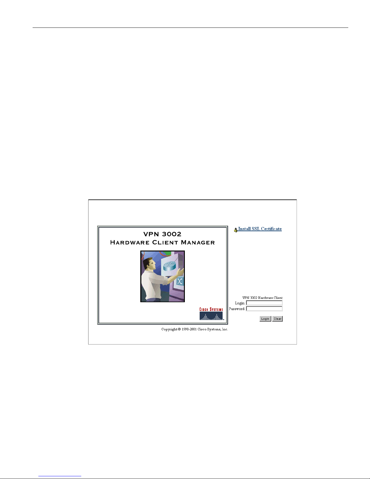
Connecting to the VPN 3002 using HTTP
When your system administration tasks and network permit a cleartext connection between the VPN
3002 and your browser, you can use the standard HTTP protocol to connect to the system.
Even if you plan to use HTTPS, you use HTTP at first to install an SSL certificate in your browser.
1 Bring up the browser.
2 In the browser
Address or Location field, you can just enter the VPN3002 Private interface IP address;
e.g.,
10.10.147.2. The browser automatically assumes and supplies an http:// prefix.
The browser displays the VPN3002 Hardware Client Manager login screen.
Figure 1-1: VPN 3302 Hardware Client Manager login screen
To continue using HTTP for the whole session, skip to Logging in the VPN 3002 Hardware Client
Manager on page 1-17.
Installing the SSL certificate in your browser
The Manager provides the option of using HTTP over SSL with the browser. SSL creates a secure
session between your browser (VPN 3002 hardware client) and the VPN Concentrator (server). This
protocol is known as HTTPS, and uses the
https:// prefix to connect to the server. The browser first
authenticates the server, then encrypts all data passed during the session.
Page 22
1 Using the VPN 3002 Hardware Client Manager
1-4
VPN 3002 Hardware Client User Guide
HTTPS is often confused with a similar protocol, S-HTTP (Secure HTTP), which encrypts only HTTP
application-level data. SSL encrypts all data between client and server at the IP socket level, and is thus
more secure.
SSL uses digital certificates for authentication. The VPN 3002 creates a self-signed SSL server
certificate when it boots, and this certificate must be installed in the browser. Once the certificate is
installed, you can connect using HTTPS. You need to install the certificate from a given VPN 3002 only
once.
Managing the VPN 3002 is the same with or without SSL. Manager screens may take slightly longer to
load with SSL because of encryption / decryption processing. When connected via SSL, the browser
shows a locked-padlock icon on its status bar. Both Microsoft Internet Explorer and Netscape Navigator
support SSL.
For HTTPS to work on the Public interface, you must enable HTTPS on the VPN 3002 through the CLI
or from an HTTP session on the Private interface first. See
Follow these steps to install and use the SSL certificate for the first time. We provide separate
instructions for Internet Explorer and Netscape Navigator when they diverge.
1 Connect to the VPN 3002 using HTTP as above.
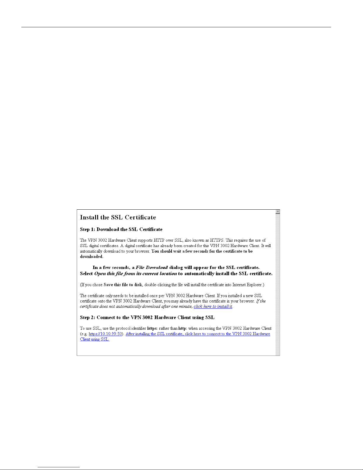
2 On the login screen, click the
Install SSL Certificate link.
The Manager displays the
Install SSL Certificate screen and automatically begins to download and install
its SSL certificate in your browser.
Figure 1-2: Install SSL Certificate screen
The installation sequence now differs depending on the browser. Continue below for Internet Explorer,
or skip to Installing the SSL certificate with Netscape on page 1-9.
Installing the SSL certificate with Internet Explorer
This section describes SSL certificate installation using Microsoft Internet Explorer 5.0. (With Internet
Explorer 4.0, some dialog boxes may differ but the process is similar.)
Page 23
Installing the SSL certificate in your browser
1-5
VPN 3002 Hardware Client User Guide
You need to install the SSL certificate from a given VPN 3002 only once. If you do reinstall it, the
browser repeats all these steps each time.
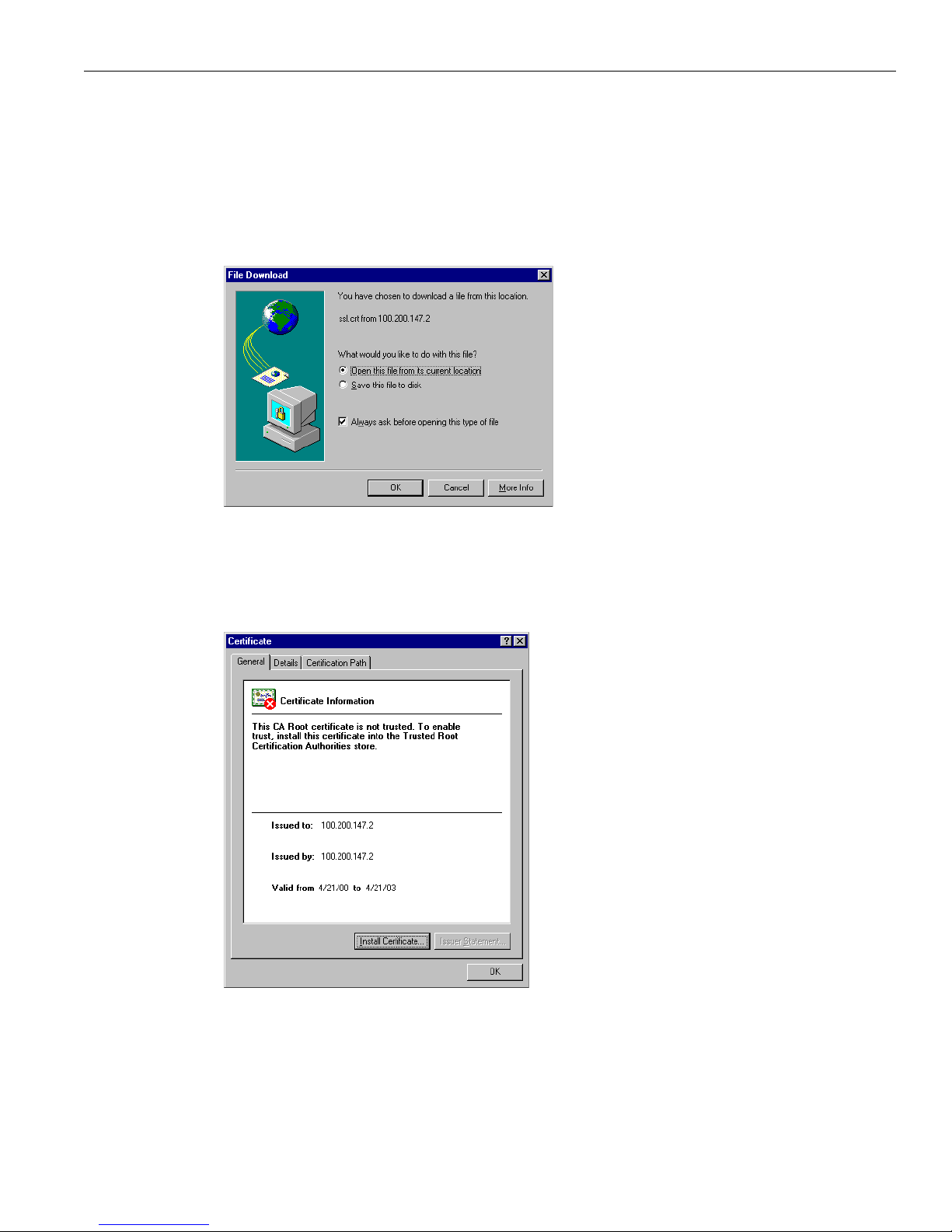
A few seconds after the VPN 3002 Hardware Client Manager SSL screen appears, Internet Explorer
displays a
File Download dialog box that identifies the certificate filename and source, and asks whether
to
Open or Save the certificate. To immediately install the certificate in the browser, select Open. If you
Save the file, the browser prompts for a location; you must then double-click on the file to install it.
Figure 1-3: Internet Explorer File Download dialog box
3 Click the Open this file from its current location radio button, then click OK.
The browser displays the
Certificate dialog box with information about the certificate. You must now
install the certificate.
Figure 1-4: Internet Explorer Certificate dialog box
4 Click Install Certificate.
The browser starts a wizard to install the certificate. The certificate store is where such certificates are
stored in Internet Explorer.
Page 24
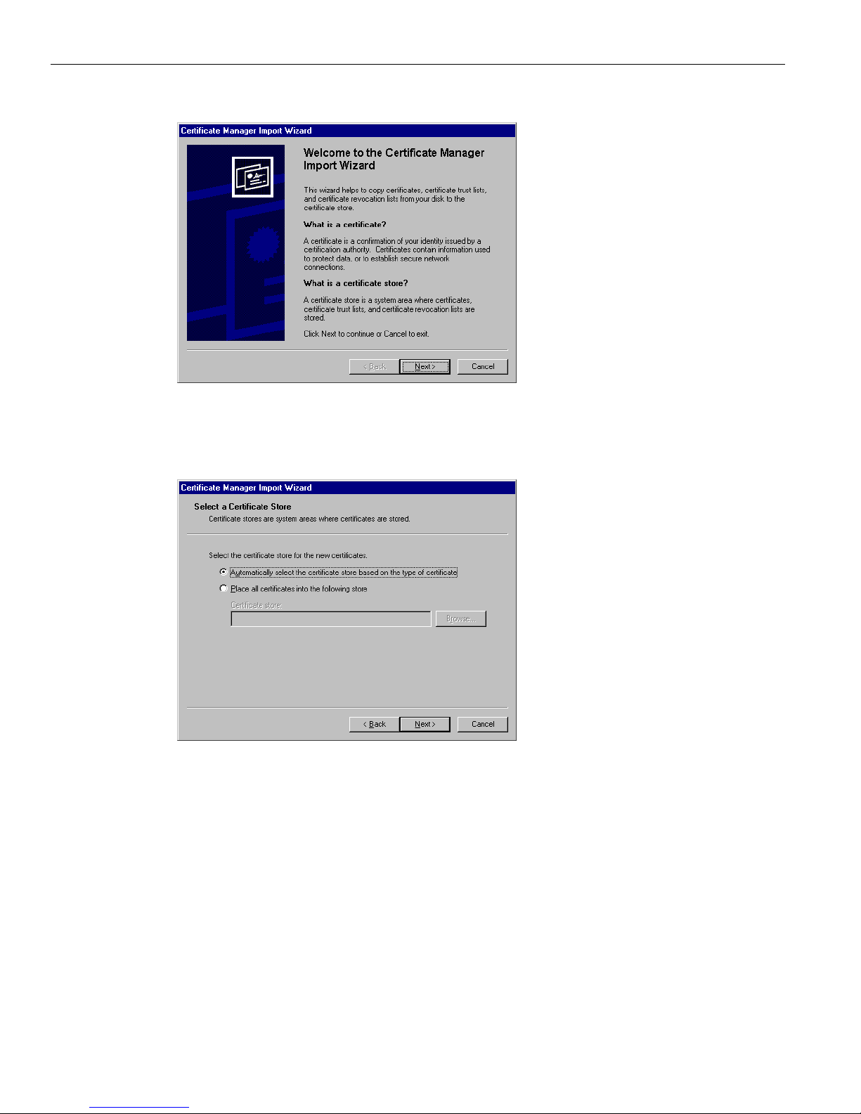
1 Using the VPN 3002 Hardware Client Manager
1-6
VPN 3002 Hardware Client User Guide
Figure 1-5: Internet Explorer Certificate Manager Import Wizard dialog box
5 Click Next to continue.
The wizard opens the next dialog box asking you to select a certificate store.
Figure 1-6: Internet Explorer Certificate Manager Import Wizard dialog box
6 Let the wizard Automatically select the certificate store, and click Next.
The wizard opens a dialog box to complete the installation.
Page 25
Installing the SSL certificate in your browser
1-7
VPN 3002 Hardware Client User Guide
Figure 1-7: Internet Explorer Certificate Manager Import Wizard dialog box
7 Click Finish.
The wizard opens the
Root Certificate Store dialog box asking you to confirm the installation.
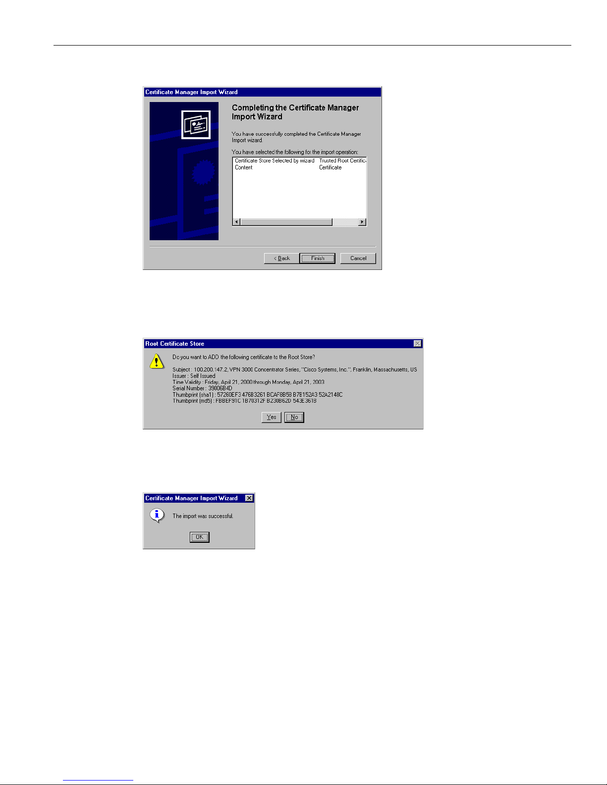
Figure 1-8: Internet Explorer Root Certificate Store dialog box
8 To install th e ce r tif icate, click Yes. This dialog box closes, and a final wizard confirmation dialog box
opens.
Figure 1-9: Internet Explorer Certificate Manager Import Wizard final dialog box
9 Click OK to close this dialog box, and click OK on the Certificate dialog box (Figure 1-4) to close it.
You can now connect to the VPN 3002 using HTTP over SSL (HTTPS).
10 On the Manager SSL screen (Figure 1-2), click the link that says,
After installing the SSL certificate,
click here to connect to the VPN 3002 Hardware Client using SSL
.
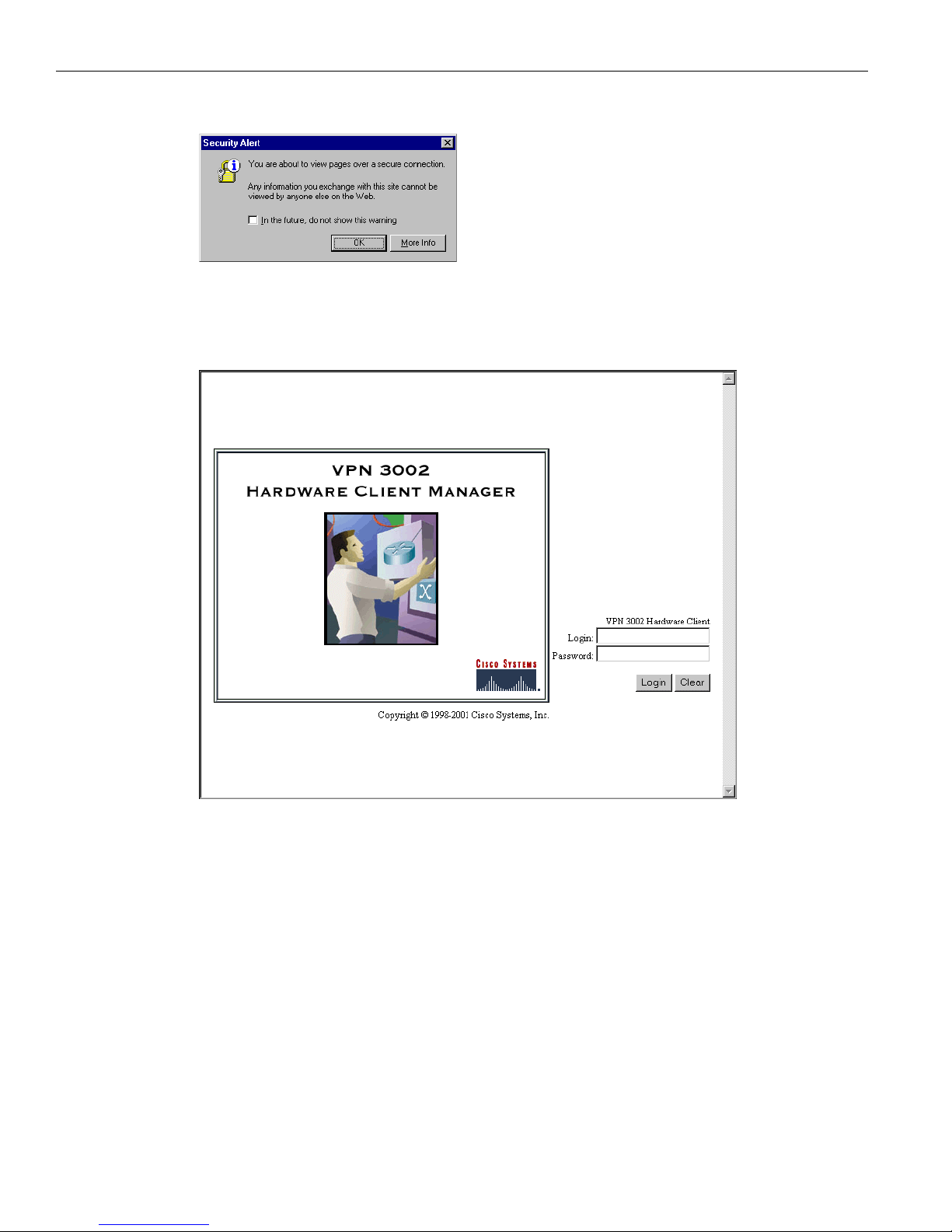
Depending on how your browser is configured, you may see a
Security Alert dialog box.
Page 26
1 Using the VPN 3002 Hardware Client Manager
1-8
VPN 3002 Hardware Client User Guide
Figure 1-10: Internet Explorer Security Alert dialog box
11 Click OK.
The VPN 3002 Hardware Client displays the HTTPS version of the Manager login screen.
Figure 1-11: VPN 3002 Hardware Client Manager login screen using HTTPS (Internet Explorer)
The browser maintains the HTTPS state until you close it or access an unsecure site; in the latter case
you may see a
Security Alert screen.
Proceed to Logging in the VPN 3002 Hardware Client Manager on page 1-17 to log in as usual.
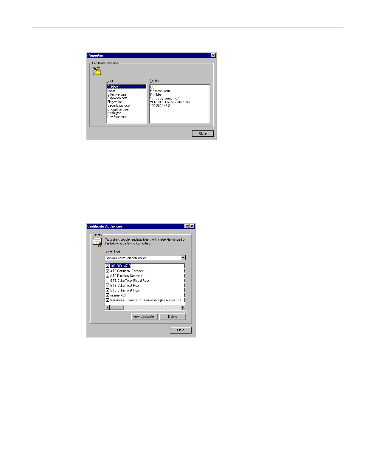
Viewing certificates with Internet Explorer
There are (at least) two ways to examine certificates stored in Internet Explorer.
First, note the padlock icon on the browser status bar in Figure 1-11. If you double-click on the icon, the
browser opens a
Certificate Properties screen showing details of the specific certificate in use.
Page 27
Installing the SSL certificate in your browser
1-9
VPN 3002 Hardware Client User Guide
Figure 1-12: Internet Explorer 4.0 Certificate Properties screen
Click any of the Field items to see Details. Click Close when finished.
Second, you can view all the certificates that are stored in Internet Explorer 4.0. Click the browser
View
menu and select
Internet Options. Click the Content tab, then click Authorities in the Certificates section.
In Internet Explorer 5.0, click the browser
To ol s menu and select Internet Options. Click the Content tab,
then click
Certificates in the Certificates section. On the Certificate Manager, click the Trusted Root
Certification Authorities
tab.
The VPN 3002 Hardware Client SSL certificate name is its Ethernet 1 (Private) IP address.
Figure 1-13: Internet Explorer 4.0 Certificate Authorities list
Select a certificate, then click View Certificate. The browser displays the Certificate Properties screen, as
in Figure 1-12 above.
Installing the SSL certificate with Netscape
This section describes SSL certificate installation using Netscape Navigator / Communicator 4.5.
Page 28
1 Using the VPN 3002 Hardware Client Manager
1-10
VPN 3002 Hardware Client User Guide
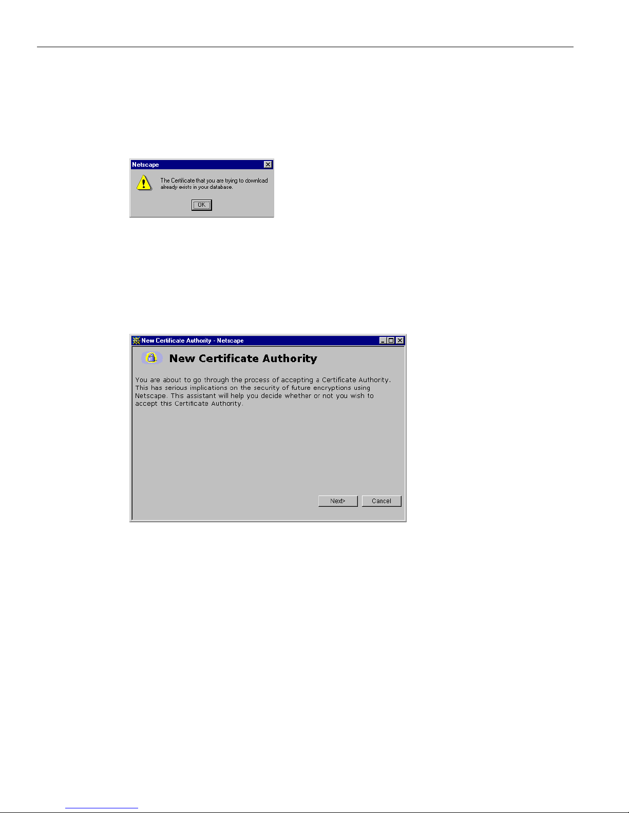
Reinstallation
You need to install the SSL certificate from a given VPN 3002 only once. If you try to reinstall it,
Netscape displays the note in Figure 1-14. Click
OK and just connect to the VPN 3002 using SSL (see
Step 7 on page 1-13).
Figure 1-14: Netscape reinstallation note
First-time installation
The instructions below follow from Step 2 on page 1-4 and describe first-time certificate installation.
A few seconds after the VPN 3002 Hardware Client Manager SSL screen appears, Netscape displays a
New Certificate Authority screen.
Figure 1-15: Netscape New Certificate Authority screen 1
1 Click Next> to proceed.
Netscape displays the next
New Certificate Authority screen, which further explains the process.
Page 29
Installing the SSL certificate in your browser
1-11
VPN 3002 Hardware Client User Guide
Figure 1-16: Netscape New Certificate Authority screen 2
2 Click Next> to proceed.
Netscape displays the next
New Certificate Authority screen, which lets you examine details of the VPN
3002 Hardware Client SSL certificate.
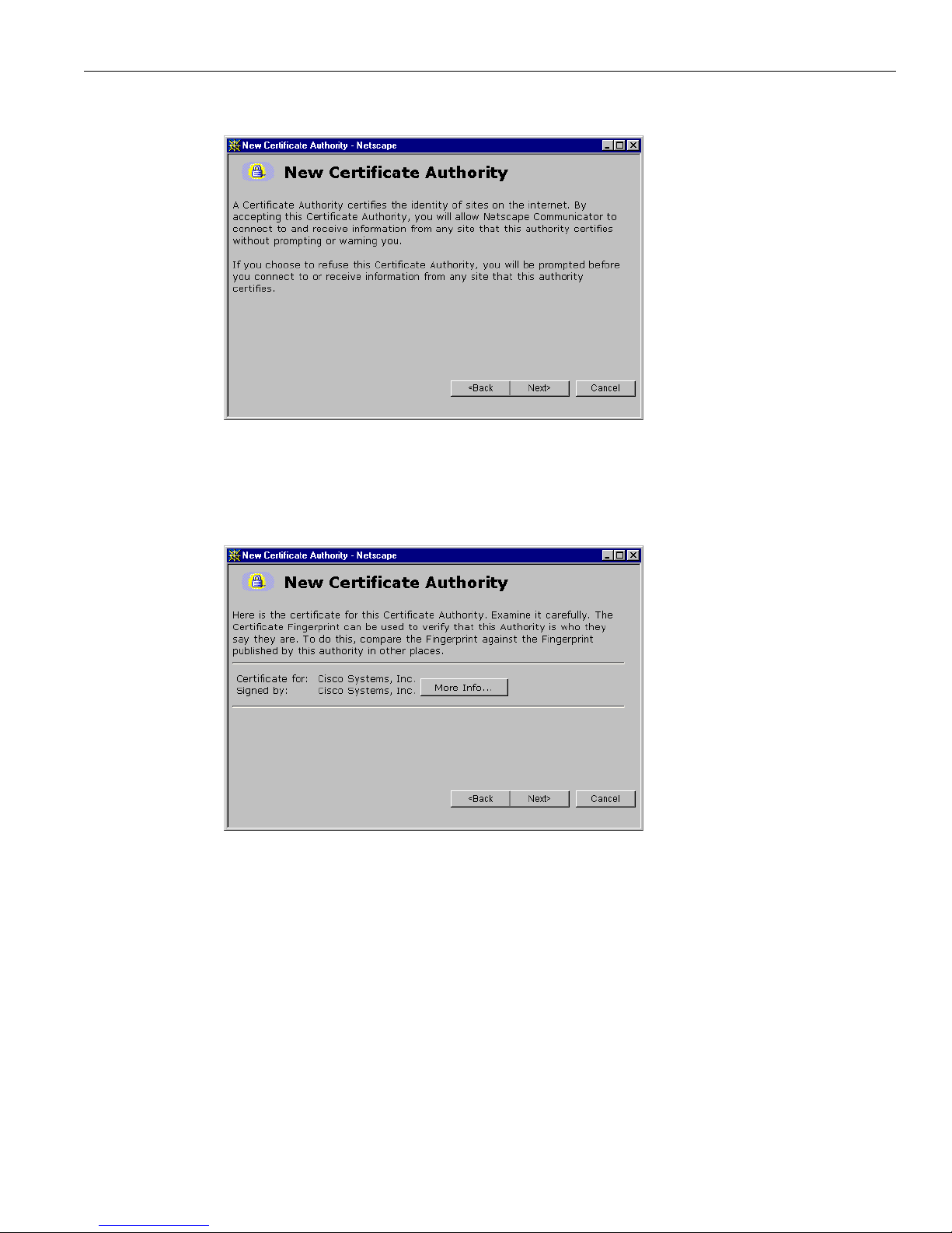
Figure 1-17: Netscape New Certificate Authority screen 3
3 Click Next> to proceed.
Netscape displays the next
New Certificate Authority screen, with choices for using the certificate. No
choices are checked by default.
Page 30
1 Using the VPN 3002 Hardware Client Manager
1-12
VPN 3002 Hardware Client User Guide
Figure 1-18: Netscape New Certificate Authority screen 4
4 You must check at least the first box, Accept this Certificate Authority for Certifying network sites. Click
Next> to proceed.
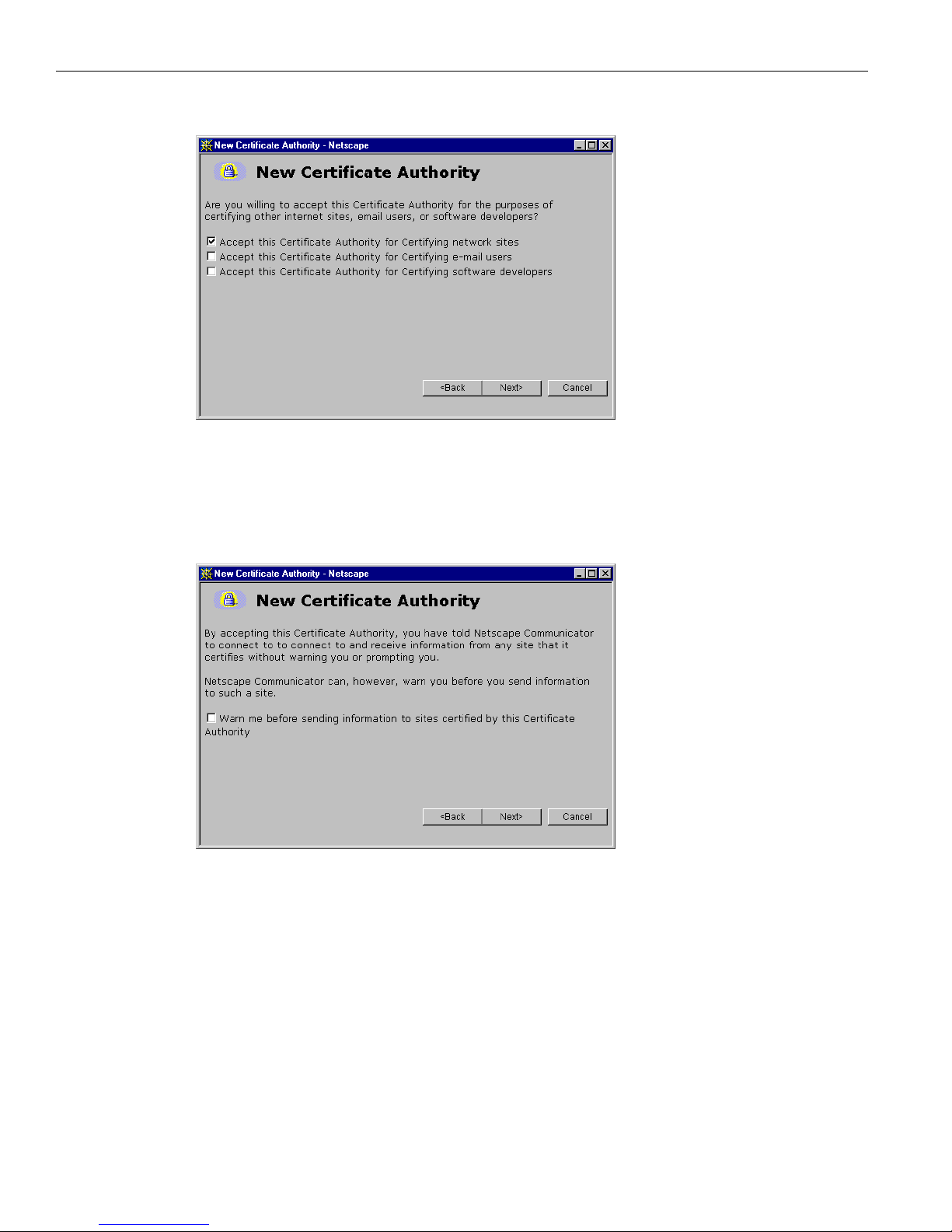
Netscape displays the next
New Certificate Authority screen, which lets you choose to have the browser
warn you about sending data to the VPN 3002.
Figure 1-19: Netscape New Certificate Authority screen 5
5 Checking the box is optional. Doing so means that you get a warning whenever you apply settings
on a Manager screen, so it’s probably less intrusive to manage the VPN 3002 without those warnings.
Click
Next> to proceed.
Netscape displays the final
New Certificate Authority screen, which asks you to name the certificate.
Page 31

Installing the SSL certificate in your browser
1-13
VPN 3002 Hardware Client User Guide
Figure 1-20: Netscape New Certificate Authority screen 6
6 In the Nickname field, enter a descriptive name for this certificate. “Nickname” is something of a
misnomer. We suggest you use a clearly descriptive name such as
Cisco VPN 3002 10.10.147.2.
This name appears in the list of installed certificates; see Viewing certificates with Netscape below.
Click
Finish.
You can now connect to the VPN 3002 using HTTP over SSL (HTTPS).
7 On the Manager SSL screen (Figure 1-2), click the link that says,
After installing the SSL certificate,
click here to connect to the VPN 3002 Hardware Client using SSL
.
Depending on how your browser is configured, you may see a
Security Information Alert dialog box.
Figure 1-21: Netscape Security Information Alert dialog box
8 Click Continue.
The VPN 3002 displays the HTTPS version of the Manager login screen.
Page 32

1 Using the VPN 3002 Hardware Client Manager
1-14
VPN 3002 Hardware Client User Guide
Figure 1-22: VPN 3002 Hardware Client Manager login screen using HTTPS (Netscape)
The browser maintains the HTTPS state until you close it or access an unsecure site; in the latter case,
you may see a
Security Information Alert dialog box.
Proceed to Logging in the VPN 3002 Hardware Client Manager on page 1-17 to log in as usual.
Viewing certificates with Netscape
There are (at least) two ways to examine certificates stored in Netscape Navigator / Communicator 4.5.
First, note the locked-padlock icon on the bottom status bar in Figure 1-22. If you click on the icon,
Netscape opens a
Security Info window. (You can also open this window by clicking Security on the
Navigator Toolbar at the top of the Netscape window.)
Page 33

Installing the SSL certificate in your browser
1-15
VPN 3002 Hardware Client User Guide
Figure 1-23: Netscape Security Info window
Click View Certificate to see details of the specific certificate in use.
Figure 1-24: Netscape View Certificate screen
Click OK when finished.
Second, you can view all the certificates that are stored in Netscape. On the
Security Info window, select
Certificates then Signers. The “nickname” you entered in Step 6 identifies the VPN 3002 Hardware Client
SSL certificate.
Page 34

1 Using the VPN 3002 Hardware Client Manager
1-16
VPN 3002 Hardware Client User Guide
Figure 1-25: Netscape Certificates Signers list
Select a certificate, then click Edit, Verify, or Delete. Click OK when finished.
Connecting to the VPN 3002 using HTTPS
Once you have installed the SSL certificate in the browser, you can connect directly using HTTPS.
1 Bring up the browser.
2 In the browser
Address or Location field, enter https:// plus the VPN 3002 private interface IP
address; for example,
https://10.10.147.2.
The browser displays the VPN 3002 Hardware Client Manager HTTPS login screen.
A locked-padlock icon on the browser status bar indicates an HTTPS session. Also, this login screen
does not include the
Install SSL Certificate link.
Page 35

Logging in the VPN 3002 Hardware Client Manager
1-17
VPN 3002 Hardware Client User Guide
Figure 1-26: VPN Hardware Client Manager HTTPS login screen
Logging in the VPN 3002 Hardware Client Manager
Logging in the VPN 3002 Hardware Client Manager is the same for both types of connections: cleartext
HTTP or secure HTTPS.
Entries are case-sensitive. With Microsoft Internet Explorer, you can press the
Tab key to move from
field to field; other browsers may work differently. If you make a mistake, click the
Clear button and start
over.
The entries that follow are the factory-supplied default entries. If you have changed them, use your
entries.
1 Click in the
Login field and type admin. (Do not press Enter.)
2 Click in the
Password field and type admin. (The field shows *****.)
3 Click the
Login button.
The Manager displays the main welcome screen.
Page 36

1 Using the VPN 3002 Hardware Client Manager
1-18
VPN 3002 Hardware Client User Guide
Figure 1-27: Manager Main Welcome screen
From here you can navigate the Manager using either the table of contents in the left frame, or the
Manager toolbar in the top frame.
Configuring HTTP, HTTPS, and SSL parameters
HTTP, HTTPS, and SSL are enabled by default on the VPN 3002, and they are configured with
recommended parameters that should suit most administration tasks and security requirements.
To configure HTTP and HTTPS parameters, see the
Configuration | System | Management Protocols | HTTP/
HTTPS
screen.
To configure SSL parameters, see the
Configuration | System | Management Protocols | SSL screen.
Page 37

Understanding the VPN 3002 Hardware Client Manager window
1-19
VPN 3002 Hardware Client User Guide
Understanding the VPN 3002 Hardware Client Manager window
The VPN 3002 Hardware Client Manager window on your browser consists of three frames — top, left,
and main — and it provides helpful messages and tips as you move the mouse pointer over window
items. The title bar and status bar also provide useful information.
Figure 1-28: VPN 3002 Hardware Client Manager window.
Title bar
The title bar at the top of the browser window includes the VPN3002 device name or IP address in
brackets; e.g.,
[10.10.104.7].
Status bar
The status bar at the bottom of the browser window displays explanatory messages for selected items
and Manager activity.
Title bar
Top frame
(Manager
Left frame
(Contents)
Main frame
(Tasks)
Status bar
Page 38

1 Using the VPN 3002 Hardware Client Manager
1-20
VPN 3002 Hardware Client User Guide
Mouse pointer and tips
As you move the mouse pointer over an active area, the pointer changes shape and icons change color.
A description also appears in the status bar area. If you momentarily rest the pointer on an icon, a
descriptive tip appears for that icon.
Top frame (Manager toolbar)
The Manager toolbar in the top frame provides quick access to Manager features.
Main tab
Click to go to the main Manager screen, and to close all subordinate sections and titles in the left frame.
Help tab
Click to open context-sensitive online help. Help opens in a separate browser window that you can move
or resize as you wish. Close the help window when you are finished.
Support tab
Click to open a Manager screen with links to Cisco support and documentation resources.
Figure 1-29: Support screen
Documentation
Click this link to open a browser window on the Cisco Technical Documentation Web page for Virtual
Private Networks. That page has links to VPN 3000 Concentrator Series and VPN 3002 Hardware Client
documentation in PDF format. (To view the PDF files, you need Adobe
®
Acrobat® Reader 3.0 or later,
and version 4.0 is included on the VPN 3000 Concentrator Series software CD-ROM.) When you finish,
close the documentation browser window and return to the Manager.
CCO at www.cisco.com
Click this link to open a browser window on the main Cisco Web page, Cisco Connection Online (CCO).
From that page, you can browse to all Cisco resources, including the Technical Assistance Center (TAC).
When you finish, close the CCO browser window and return to the Manager.
Page 39

Understanding the VPN 3002 Hardware Client Manager window
1-21
VPN 3002 Hardware Client User Guide
tac@cisco.com
Click this link to open your configured email application and compose an email message to Cisco’s
Technical Assistance Center (TAC). When you finish, the application closes and returns to this
Support
screen.
Logout tab
Click to log out of the Manager and return to the login screen.
Logged in: [username]
The administrator username you used to log in to this Manager session.
Configuration tab
Click to go to the main Configuration screen, to open the first level of subordinate Configuration pages
in the left frame if they are not already open, and to close Administration or Monitoring pages in the left
frame.
Administration tab
Click to go to the main Administration screen, to open the first level of subordinate Administration pages
in the left frame if they are not already open, and to close Configuration or Monitoring pages in the left
frame.
Monitoring tab
Click to go to the main Monitoring screen, to open the first level of subordinate Monitoring pages in the
left frame if they are not already open, and to close Configuration or Administration pages in the left
frame.
Save
The Save button displays in the detailed configuration screens. Click to save the active configuration
and make it the boot configuration. In this state, the reminder indicates that the active configuration is
the same as the boot configuration, but you can save it anyway. When you change the configuration, the
reminder changes to
Save Needed.
Save Needed
This reminder indicates that you have changed the active configuration. Click to save the active
configuration and make it the boot configuration. As you make configuration entries, they take effect
immediately and are included in the active, or running, configuration. However, if you reboot the VPN
3002 Hardware Client without saving the active configuration, any configuration changes are lost.
Clicking this reminder saves the active configuration as the boot configuration and restores the
Save
reminder.
In Quick Configuration, as in the detailed configuration screens, you changes take effect immediately
and become the active configuration. There is a difference, however, in that the Manager saves the new
Page 40

1 Using the VPN 3002 Hardware Client Manager
1-22
VPN 3002 Hardware Client User Guide
configuration automatically when you reach the Done screen, and there is neither the Save o r Save Needed
button.
Refresh
Click to refresh (update) the screen contents on screens where it appears (mostly in the Monitoring
section). The date and time above this reminder indicate when the screen was last updated.
Cisco Systems logo
Click the Cisco Systems logo to open a browser and go to the Cisco web site, www.cisco.com.
Left frame (Table of contents)
The left frame provides a table of contents to Manager screens. The table of contents uses the familiar
Windows Explorer metaphor of collapsed and expanded entries.
Main section titles (Configuration, Administration, Monitoring)
Click a title to open subordinate sections and titles, and to go to that Manager screen in the main frame.
Closed or collapsed
Click the closed / collapsed icon to open subordinate sections and titles. Clicking this icon does not
change the screen in the main frame.
Open or expanded
Click the open / expanded icon to close subordinate sections and titles. Clicking this icon does not
change the screen in the main frame.
Main frame (Manager screen)
The main frame displays the current VPN 3002 Hardware Client Manager screen.
Many screens include a bullet list of links and descriptions of subordinate sections and titles. You can
click a link to go to that Manager screen and open subordinate sections and titles in the table of contents.
Organization of the VPN 3002 Hardware Client Manager
The VPN 3002 Hardware Client Manager consists of three major sections and many subsections:
•
Configuration: setting all the parameters for the VPN 3002 that govern its use and functionality as a
VPN device:
–
Quick Configuration: supplying the minimal parameters needed to make the VPN 3002 operational.
–
Interfaces: Ethernet parameters.
Page 41

Navigating the VPN 3002 Hardware Client Manager
1-23
VPN 3002 Hardware Client User Guide
– System: parameters for system-wide functions such as server access, IPSec tunneling protocol,
built-in management servers, event handling, and system identification.
–
Policy Management: enabling PAT (Port Address Translation).
• Administration: managing higher level functions that keep the VPN3002 operational and secure, such
as who is allowed to configure the system, what software runs on it, and managing its configuration
files and digital certificates.
•
Monitoring: viewing routing tables, event logs, system LEDs and status, and data on user sessions
This manual covers all these topics. For Quick Configuration, see the VPN 3002 Hardware Client
Getting Started manual.
Navigating the VPN 3002 Hardware Client Manager
Your primary tool for navigating the VPN 3002 Hardware Client Manager is the table of contents in the
left frame. Figure 1-30 shows all its entries, completely expanded. (The figure shows the frame in
multiple columns, but the actual frame is a single column. Use the scroll controls to move up and down
the frame.)
Figure 1-30: Complete Manager Table of Contents
Page 42

Page 43

2-1
VPN 3002 Hardware Client User Guide
CHAPTER
2
Configuration
Configuring the VPN 3002 means setting all the parameters that govern its use and functionality as a
VPN device.
Cisco supplies default parameters that cover typical installations and uses; and once you supply minimal
parameters in Quick Configuration, the system is operational. But to tailor the system to your needs, and
to provide an appropriate level of system security, you can configure the system in detail.
Configuration
This section of the Manager lets you configure all VPN 3002 features and functions.
•
Quick Configuration: the minimal parameters needed to make the VPN 3002 operational. For more
information, use
online Help, or see the VPN 3002 Getting Started manual, available online only.
• Interfaces: parameters specific to the Private and Public interfaces.
• System: parameters for system-wide functions: server access, IPSec, IP routing, built-in management
servers, system events, and system identification.
•
Policy Management: enabling or disabling PAT (Protocol Address Translation).
Figure 2-1: Configuration screen
See the appropriate chapter in this manual for each section of the Manager. Online help is available for
all sections.
Page 44

Page 45

3-1
VPN 3002 Hardware Client User Guide
CHAPTER
3
Interfaces
This section of the VPN 3002 Hardware Client Manager applies functions that are interface-specific,
rather than system-wide.
You configure two network interfaces for the VPN 3002 to operate as a VPN device: the Private interface
and the Public interface. If you used Quick Configuration as described in the VPN 3002 Hardware Client
Getting Started manual, the system supplied many default parameters for the interfaces. Here you can
configure them explicitly.
The VPN 3002 includes some IP routing functions: static routes, and DHCP. You configure static routes,
the default gateway, and DHCP in the IP Routing section; see the
Configuration | System | IP Routing
screens.
Configuration | Interfaces
This section lets you configure the Private and Public interfaces.
• Private is the interface to your private network (internal LAN).
• Public is the interface to the public network.
Configuring an Ethernet interface includes supplying an IP address and subnet mask, and setting speed
and transmission mode.
Note: Interface settings take effect as soon as you apply them. If the system is in active use, changes may affect
tunnel traffic.
The table shows all installed interfaces and their status.
Page 46

3 Interfaces
3-2
VPN 3002 Hardware Client User Guide
Figure 3-1: VPN 3002-8E Configuration | Interfaces screen
To configure a module, either click the appropriate link in the status table; or use the mouse pointer to
select the module on the back-panel image, and click anywhere in the highlighted area.
Interface
The VPN3002 interface installed in the system. To configure an interface, click the appropriate link.
Private, Public
To configure Ethernet interface parameters, click the appropriate highlighted link in the table or click in
a highlighted module on the back-panel image. See
Configuration | Interfaces | Private/Public.
Status
The operational status of this interface
PWR green = Configured, enabled, and operational; ready to pass data traffic.
SYS flashing amber = Configured but disabled or disconnected.
Testing = In test mode; no regular data traffic can pass.
Dormant = (Red) Configured and enabled but waiting for an external action, such as an incoming
connection.
Not Present = (Red) Missing hardware components.
Lower Layer Down = (Red) Not operational because a lower-layer interface is down.
Unknown = (Red) Not configured or not able to determine status.
Not Configured = Present but not configured.
Waiting for DHCP = Waiting for DHCP to assign an IP address.
Page 47

Configuration | Interfaces | Private
3-3
VPN 3002 Hardware Client User Guide
IP Address
The IP address configured on this interface.
Subnet Mask
The subnet mask configured on this interface.
Configuration | Interfaces | Private
This screen lets you configure parameters for the Private Interface. It displays the current parameters, if
any.
Figure 3-2: Configuration | Interfaces | Private screen
Caution: If you modify any parameters of the Private interface that you are currently using to connect to the VPN
3002, you will break the connection, and you will have to restart the Manager from the login screen.
Enabled
To make the interface functional and online, check Enabled. If not enabled, the interface is offline; this
state lets you retain or change its configuration parameters while it is offline.
Page 48

3 Interfaces
3-4
VPN 3002 Hardware Client User Guide
If the interface is configured but disabled (offline), the appropriate Ethernet Link Status LED blinks green
on the VPN 3002 front panel.
IP Address
Enter the IP address for this interface, using dotted decimal notation (e.g., 192.168.12.34). Note that
0.0.0.0 is not allowed. Be sure no other device is using this address on the network.
Subnet Mask
Enter the subnet mask for this interface, using dotted decimal notation (e.g., 255.255.255.0). The
Manager automatically supplies a standard subnet mask appropriate for the IP address you just entered.
For example, the IP address
192.168.12.34 is a Class C address, and the standard subnet mask is
255.255.255.0. You can accept this entry or change it. Note that 0.0.0.0 is not allowed.
MAC Address
This is the unique hardware MAC (Medium Access Control) address for this interface, displayed in
6-byte hexadecimal notation. You cannot change this address.
Speed
Click the drop-down menu button and select the interface speed:
10 Mbps = Fix the speed at 10 megabits per second (10Base-T networks)
100 Mbps = Fix the speed at 100 megabits per second (100Base-T networks)
10/100 auto = Let the VPN 3002 automatically detect and set the appropriate speed, either 10 or 100
Mbps (default). Be sure that the port on the active network device (hub, switch, router, etc.) to
which you connect this interface is also set to automatically negotiate the speed. Otherwise, select
the appropriate fixed speed.
Duplex
Click the drop-down menu button and select the interface transmission mode:
Auto = Let the VPN 3002 automatically detect and set the appropriate transmission mode, either full
or half duplex (default). Be sure that the port on the active network device (hub, switch, router, etc.)
to which you connect this interface is also set to automatically negotiate the transmission mode.
Otherwise, select the appropriate fixed mode.
Full-Duplex = Fix the transmission mode as full duplex: transmits and receives at the same time.
Half-Duplex = Fix the transmission mode as half duplex: transmits or receives, but not at the same
time.
Page 49

Configuration | Interfaces | Public
3-5
VPN 3002 Hardware Client User Guide
Apply / Cancel
To apply your settings to the system and include them in the active configuration, click Apply. The
Manager returns to the
Configuration | Interfaces screen.
Reminder: To save the active configuration and make it the boot configuration, click the
Save Needed icon at the
top of the Manager window.
To discard your settings, click
Cancel. The Manager returns to the Configuration | Interfaces screen.
Configuration | Interfaces | Public
This screen lets you configure general interface parameters for the Public interface.
Figure 3-3: Configuration | Interfaces | Public screen
Enabled
To make the interface functional and online, check Enabled. If not enabled, the interface is offline; this
state lets you retain or change its configuration parameters while it is offline.
DHCP Client
Check this box if you want to obtain the IP address and subnet mask for this interface via DHCP. If you
check this box, you don’t make entries in the IP address and subnet mask parameters that follow.
Page 50

3 Interfaces
3-6
VPN 3002 Hardware Client User Guide
IP Address
Enter the IP address for this interface, using dotted decimal notation (e.g., 192.168.12.34). Note that
0.0.0.0 is not allowed. Be sure no other device is using this address on the network.
Subnet Mask
Enter the subnet mask for this interface, using dotted decimal notation (e.g., 255.255.255.0). The
Manager automatically supplies a standard subnet mask appropriate for the IP address you just entered.
For example, the IP address
192.168.12.34 is a Class C address, and the standard subnet mask is
255.255.255.0. You can accept this entry or change it. Note that 0.0.0.0 is not allowed.
MAC Address
This is the unique hardware MAC (Medium Access Control) address for this interface, displayed in
6-byte hexadecimal notation. You cannot change this address.
Speed
Click the drop-down menu button and select the interface speed:
10 Mbps = Fix the speed at 10 megabits per second (10Base-T networks)
100 Mbps = Fix the speed at 100 megabits per second (100Base-T networks)
10/100 auto = Let the VPN 3002 automatically detect and set the appropriate speed, either 10 or 100
Mbps (default). Be sure that the port on the active network device (hub, switch, router, etc.) to
which you connect this interface is also set to automatically negotiate the speed. Otherwise, select
the appropriate fixed speed.
Duplex
Click the drop-down menu button and select the interface transmission mode:
Auto = Let the VPN 3002 automatically detect and set the appropriate transmission mode, either full
or half duplex (default). Be sure that the port on the active network device (hub, switch, router, etc.)
to which you connect this interface is also set to automatically negotiate the transmission mode.
Otherwise, select the appropriate fixed mode.
Full-Duplex = Fix the transmission mode as full duplex: transmits and receives at the same time.
Half-Duplex = Fix the transmission mode as half duplex: transmits or receives, but not at the same
time.
Apply / Cancel
To apply your settings to this interface and include your settings in the active configuration, click Apply.
The Manager returns to the
Configuration | Interfaces screen.
Reminder: To save the active configuration and make it the boot configuration, click the
Save Needed icon at the
top of the Manager window.
To discard your settings, click
Cancel. The Manager returns to the Configuration | Interfaces screen.
Page 51

4-1
VPN 3002 Hardware Client User Guide
CHAPTER
4
System Configuration
System configuration means configuring parameters for system-wide functions in the VPN 3002.
Configuration | System
This section of the Manager lets you configure parameters for:
•
Servers: identifying servers for DNS information for the VPN 3002.
• Tunneling Protocols: configuring IPSec connections.
• IP Routing: configuring static routes, default gateways, and DHCP.
• Management Protocols: configuring and enabling built-in servers for HTTP/HTTPS, Telnet, SNMP,
SSL and SSH.
•
Events: handling system events via logs, SNMP traps, and syslog.
• General: identifying the system and setting the time and date.
Seethe appropriate chapter in this manual or the online help for each section.
Figure 4-1: Configuration | System screen
Page 52

Page 53

5-1
VPN 3002 Hardware Client User Guide
CHAPTER
5
Servers
Configuring servers means identifying them to the VPN 3002 so it can communicate with them correctly.
For the VPN 3002, these are DNS servers that convert hostnames to IP addresses. The VPN 3002
functions as a client of these servers.
Configuration | System | Servers
This section of the Manager lets you configure the VPN 3002 to communicate with DNS servers.
Figure 5-1: Configuration | System | Servers screen
Configuration | System | Servers | DNS
This screen lets you configure the Domain Name System (DNS) servers for the VPN 3002. DNS servers
convert domain names to IP addresses. Configuring DNS servers here lets you enter hostnames (e.g.,
mail01) rather than IP addresses as you configure and manage the VPN 3002.
You can configure up to three DNS servers that the system queries in order.
Note: DNS information that you add here is for the VPN 3002 only. PCs located behind the VPN 3002 on the
private network get DNS information that is configured on the central-site Concentrator in the Group
settings for the VPN 3002.
Page 54

5 Servers
5-2
VPN 3002 Hardware Client User Guide
Figure 5-2: Configuration | System | Servers | DNS screen
Enabled
To use DNS functions, check Enabled (the default). To disable DNS, clear the box.
Domain
Enter the name of the registered domain of the ISP for the VPN 3002; e.g., yourisp.com. Maximum
48 characters. This entry is sometimes called the domain name suffix or sub-domain. The DNS system
within the VPN 3002 automatically appends this domain name to hostnames before sending them to a
DNS server for resolution.
Primary DNS Server
Enter the IP address of the primary DNS server, using dotted decimal notation; e.g., 192.168.12.34.
Be sure this entry is correct to avoid DNS resolution delays.
Secondary DNS Server
Enter the IP address of the secondary (first backup) DNS server, using dotted decimal notation. If the
primary DNS server doesn’t respond to a query within the
Timeout Period specified below, the system
queries this server.
Tertiary DNS Server
Enter the IP address of the tertiary (second backup) DNS server, using dotted decimal notation. If the
secondary DNS server doesn’t respond to a query within the
Timeout Period specified below, the system
queries this server.
Page 55

Configuration | System | Servers | DNS
5-3
VPN 3002 Hardware Client User Guide
Timeout Period
Enter the initial time in seconds to wait for a response to a DNS query before sending the query to the
next server. Minimum is
1, default is 2, maximum is 30 seconds. This time doubles with each retry cycle
through the list of servers.
Timeout Retries
Enter the number of times to retry sending a DNS query to the configured servers, in order. In other
words, this is the number of times to cycle through the list of servers before returning an error. Minimum
is
0, default is 2, maximum is 10 retries.
Apply / Cancel
To apply your settings for DNS servers and include the settings in the active configuration, click Apply.
The Manager returns to the
Configuration | System | Servers screen.
Reminder: To save the active configuration and make it the boot configuration, click the
Save Needed icon at the
top of the Manager window.
To discard your settings, click
Cancel. The Manager returns to the Configuration | System | Servers screen.
Page 56

Page 57

6-1
VPN 3002 Hardware Client User Guide
CHAPTER
6
Tunneling
Tunneling is the heart of virtual private networking. The tunnels make it possible to use a public TCP/
IP network, such as the Internet, to create secure connections between remote users and a private
corporate network.
The secure connection is called a tunnel, and the VPN 3002 uses the IPSec tunneling protocol to:
• Negotiate tunnel parameters.
• Establish tunnels.
• Authenticate users and data.
• Manage security keys.
• Encrypt and decrypt data.
• Manage data transfer across the tunnel.
• Manage data transfer inbound and outbound as a tunnel endpoint.
The VPN 3002 functions as a bidirectional tunnel endpoint: it can receive plain packets from the private
network, encapsulate them, create a tunnel, and send them to the other end of the tunnel where they are
unencapsulated and sent to their final destination; or it can receive encapsulated packets from the public
network, unencapsulate them, and send them to their final destination on the private network.
This section explains how to configure the IPSec tunneling protocol.
Page 58

6 Tunneling
6-2
VPN 3002 Hardware Client User Guide
Configuration | System | Tunneling Protocols
This section lets you configure the IPSec tunneling protocol.
1 Click
IPSec.
Figure 6-1: Configuration | System | Tunneling Protocols screen
Configuration | System | Tunneling Protocols | IPSec
The VPN 3002 complies with the IPSec protocol and is specifically designed to work with the VPN
Concentrator. IPSec provides the most complete architecture for VPN tunnels, and it is perceived as the
most secure protocol.
In IPSec terminology, a “peer” is a remote-access client or another secure gateway. During tunnel
establishment under IPSec, the two peers negotiate Security Associations that govern authentication,
encryption, encapsulation, key management, etc. These negotiations involve two phases: first, to
establish the tunnel (the IKE SA); and second, to govern traffic within the tunnel (the IPSec SA).
The VPN 3002 initiates all tunnels with the VPN Concentrator; the Concentrator functions only as
responder. The VPN 3002 as initiator propose SAs; the responder accepts, rejects, or makes
counter-proposals—all according to configured SA parameters. To establish a connection, both entities
must agree on the SAs.
The Cisco VPN 3002 supports these IPSec attributes, but they are configurable on the central-site
Concentrator, not on the VPN 3002:
• Main mode for negotiating phase one of establishing ISAKMP Secure Associations (SAs)
• Aggressive mode for negotiating phase one of establishing ISAKMP SAs
• Authentication Algorithms:
– ESP-MD5-HMAC-128
– ESP-SHA1-HMAC-160
• Authentication Modes:
– Preshared Keys
– X.509 Digital Certificates
• Diffie-Hellman Groups 1and 2
• Encryption Algorithms:
– DES-56
– 3DES-168
• Extended Authentication (XAuth)
Page 59

Configuration | System | Tunneling Protocols | IPSec
6-3
VPN 3002 Hardware Client User Guide
• Mode Configuration (also known as ISAKMP Configuration Method)
• Tunnel Encapsulation Mode
Figure 6-2: Configuration | System | Tunneling Protocols | IPSec screen
Peer Address
Enter the IP address or hostname of the remote IKE peer. This is the IP address or hostname of the public
interface on the VPN Concentrator to which this VPN 3002 connects. Use dotted decimal notation; e.g.,
192.168.34.56.
Use Certificate
This parameter specifies whether to use preshared keys or a PKI (Public Key Infrastructure) digital
identity certificate to authenticate the peer during Phase 1 IKE negotiations. See the discussion under
Administration | Certificate Management, which is where you install digital certificates on the VPN 3002.
Check the box to use digital certificates.
Group
The VPN 3002 connects to the VPN 3000 Series Concentrator using this Group name and password, which
must be configured on the central-site Concentrator. Group and user names and passwords must be identical
on the VPN 3002 and on the Concentrator to which it connects.
Name
In the Group Name field, enter a unique name for the group to which this VPN 3002 belongs. This is the
group name configured on the central-site Concentrator to which this VPN 3002 connects. Maximum is
32 characters, case-sensitive.
Password
In the Group Password field, enter a unique password for this group. This is the group password
configured on the Concentrator to which this VPN 3002 connects. Minimum is 4, maximum is 32
characters, case-sensitive. The field displays only asterisks.
Page 60

Verify
In the Group Verify field, re-enter the group password to verify it. The field displays only asterisks.
User
You must also enter a username and password, and they must match the username and password
configured on the central-site Concentrator to which this VPN 3002 connects.
Name
In the User Name field, enter a unique name for the user in this group. Maximum is 32 characters,
case-sensitive.This is the user name configured on the central-site Concentrator to which this VPN 3002
connects. Maximum is 32 characters, case-sensitive.
Password
In the User Password field, enter the password for this user. This is the user password configured on the
central-site Concentrator to which this VPN 3002 connects. Minimum is 4, maximum is 32 characters,
case-sensitive.
Verify
In the User Verify field, re-enter the user password to verify it. The field displays only asterisks.
Page 61

7-1
VPN 3002 Hardware Client User Guide
CHAPTER
7
IP Routing
The VPN 3002 itself includes an IP routing subsystem with static routing, default gateways, and DHCP.
To route packets, the subsystem uses static routes and the default gateway. If you don’t configure the
default gateway, the subsystem drops packets that it can’t otherwise route.
You configure static routes and default gateways in this section. This section also includes the
system-wide DHCP (Dynamic Host Configuration Protocol) server parameters.
Configuration | System | IP Routing
This section of the Manager lets you configure system-wide IP routing parameters.
•
Static Routes: manually configured routing tables.
• Default Gateways: routes for otherwise unrouted traffic.
• DHCP: Dynamic Host Configuration Protocol global parameters.
• DHCP Options: facilities that allow the VPN 3002 DHCP server to respond with configurable
parameters for specific kinds of devices such as PCs, IP telephones, print servers, etc., as well as an
IP address.
Figure 7-1: Configuration | System | IP Routing screen
Page 62

7 IP Routing
7-2
VPN 3002 Hardware Client User Guide
Configuration | System | IP Routing | Static Routes
This section of the Manager lets you configure static routes for IP routing.
Figure 7-2: Configuration | System | IP Routing | Static Routes screen
Static Routes
The Static Routes list shows manual IP routes that have been configured. The format is [destination
network address/subnet mask -> outbound destination]
; e.g., 192.168.12.0/
255.255.255.0 -> 10.10.0.2
. If you have configured the default gateway, it appears first in the
list as
[Default -> default router address]. If no static routes have been configured, the list
shows
--Empty--.
Add / Modify / Delete
To configure and add a new static route, click Add. The Manager opens the Configuration | System | IP
Routing | Static Routes | Add
screen.
To modify a configured static route, select the route from the list and click
Modify. The Manager opens
the
Configuration | System | IP Routing | Static Routes | Modify screen. If you select the default gateway, the
Manager opens the
Configuration | System | IP Routing | Default Gateways screen.
To delete a configured static route, select the route from the list and click
Delete. There is no
confirmation or undo. The Manager refreshes the screen and shows the remaining static routes in the
list. You cannot delete the default gateways here; to do so, see the
Configuration | System | IP Routing |
Default Gateways
screen.
Reminder: The Manager immediately includes your changes in the active configuration. To save the active
configuration and make it the boot configuration, click the
Save Needed icon at the top of the Manager
window.
Page 63

Configuration | System | IP Routing | Static Routes | Add or Modify
7-3
VPN 3002 Hardware Client User Guide
Configuration | System | IP Routing | Static Routes |
Add or Modify
These Manager screens let you:
Add: Configure and add a new static, or manual, route to the IP routing table.
Modify: Modify the parameters for a configured static route.
Figure 7-3: Configuration | System | IP Routing | Static Routes | Add or Modify screen
Network Address
Enter the destination network IP address that this static route applies to. Packets with this destination
address will be sent to the
Destination below. Used dotted decimal notation; e.g., 192.168.12.0.
Subnet Mask
Enter the subnet mask for the destination network IP address, using dotted decimal notation (e.g.,
255.255.255.0). The subnet mask indicates which part of the IP address represents the network and
which part represents hosts. The router subsystem looks at only the network part.
The Manager automatically supplies a standard subnet mask appropriate for the IP address you just
entered. For example, the IP address
192.168.12.0 is a Class C address, and the standard subnet mask
is
255.255.255.0. You can accept this entry or change it. Note that 0.0.0.0 is not allowed here, since
that would resolve to the equivalent of a default gateway.
Metric
Enter the metric, or cost, for this route. Use a number from 1 to 16, where 1 is the lowest cost. The
routing subsystem always tries to use the least costly route. For example, if a route uses a low-speed line,
you might assign a high metric so the system will use it only if all high-speed routes are unavailable.
Page 64

7 IP Routing
7-4
VPN 3002 Hardware Client User Guide
Destination
Click a radio button to select the outbound destination for these packets. You can select only one
destination: either a specific router/gateway, or a VPN 3002 interface.
Destination Router Address
Enter the IP address of the specific router or gateway to which to route these packets; that is, the IP
address of the next hop between the VPN 3002 and the packet’s ultimate destination. Use dotted decimal
notation; e.g.,
10.10.0.2. We recommend that you select this option.
Interface
Click the drop-down menu button and select a configured VPN 3002 interface as the outbound
destination. We do not recommend this option; enter a destination router address above.
Add or Apply / Cancel
To add a new static route to the list of configured routes, click Add. Or to apply your changes to a static
route, click
Apply. Both actions include your entries in the active configuration. The Manager returns to
the
Configuration | System | IP Routing | Static Routes screen. Any new route appears at the bottom of the
Static Routes list.
Reminder: To save the active configuration and make it the boot configuration, click the
Save Needed icon at the
top of the Manager window.
To discard your entries, click
Cancel. The Manager returns to the Configuration | System | IP Routing | Static
Routes
screen, and the Static Routes list is unchanged.
Configuration | System | IP Routing | Default Gateways
This screen lets you configure the default gateway for IP routing. You use this same screen both to
initially configure and to change default gateways. You can also configure the default gateway on the
Configuration | Quick | System Info screen.
The IP routing subsystem routes data packets first using static routes, then the default gateway. If you
don’t specify a default gateway, the system drops packets it can’t otherwise route.
Figure 7-4: Configuration | System | IP Routing | Default Gateways screen
Page 65

Configuration | System | IP Routing | DHCP
7-5
VPN 3002 Hardware Client User Guide
Default Gateway
Enter the IP address of the default gateway or router. Use dotted decimal notation; e.g.,
192.168.12.77. This address must not be the same as the IP address configured on any VPN 3002
interface. If you do not use a default gateway, enter
0.0.0.0 (the default entry).
To delete a configured default gateway, enter
0.0.0.0.
The default gateway must be reachable from a VPN 3002 interface, and it is usually on the public
network. The Manager displays a warning screen if you enter an IP address that is not on one of its
interface networks, and it displays a dialog box if you enter an IP address that is not on the public
network.
Metric
Enter the metric, or cost, for the route to the default gateway. Use a number from 1 to 16, where 1 is the
lowest cost. The routing subsystem always tries to use the least costly route. For example, if this route
uses a low-speed line, you might assign a high metric so the system will use it only if all high-speed
routes are unavailable.
Apply / Cancel
To apply the settings for default gateways, and to include your settings in the active configuration, click
Apply. The Manager returns to the Configuration | System | IP Routing screen. If you configure a Default
Gateway
, it also appears in the Static Routes list on the Configuration | System | IP Routing | Static Routes
screen.
Reminder: To save the active configuration and make it the boot configuration, click the
Save Needed icon at the
top of the Manager window.
To discard your entries, click
Cancel. The Manager returns to the Configuration | System | IP Routing screen.
Configuration | System | IP Routing | DHCP
This screen lets you configure DHCP (Dynamic Host Configuration Protocol) server parameters that
apply to DHCP server functions within the VPN 3002.
The DHCP server for the Private interface lets IP hosts in its network automatically obtain IP addresses
from a limited pool of addresses for a fixed length of time, or lease period. Before the lease period
expires, the VPN 3002 displays a message offering to renew it. If the lease is not renewed, the connection
terminates when the lease expires, and the IP address becomes available for reuse. Using DHCP
simplifies configuration since you do not need to know what IP addresses are considered valid on a
particular network.
Page 66

7 IP Routing
7-6
VPN 3002 Hardware Client User Guide
Figure 7-5: Configuration | System | IP Routing | DHCP screen
Enabled
Check the box to enable the DHCP server functions on the VPN 3002. The box is checked by default.
To use DHCP address assignment, you must enable DHCP functions here.
Lease Timeout
Enter the timeout in minutes for addresses that are obtained from the DHCP server. Minimum is 5,
default is
120, maximum is 500000 minutes. DHCP servers “lease” IP addresses to clients on the VPN
3002’s private network for this period of time.
Address Pool Start/End
Enter the range of IP addresses that the DHCP server can assign. Use dotted decimal notation. The
default is 127 successive addresses, with the first address being the address immediately after that of the
private interface. The maximum number of addresses you can configure is 127.
Apply / Cancel
To apply the settings for DHCP parameters, and to include your settings in the active configuration, click
Apply. The Manager returns to the Configuration | System | IP Routing screen.
Reminder: To save the active configuration and make it the boot configuration, click the
Save Needed icon at the
top of the Manager window.
To discard your entries, click
Cancel. The Manager returns to the Configuration | System | IP Routing screen.
Page 67

Configuration | System | IP Routing | DHCP Options
7-7
VPN 3002 Hardware Client User Guide
Configuration | System | IP Routing | DHCP Options
This section lets you configure DHCP options.
Figure 7-6: Configuration | System | IP Routing | DHCP Options screen
DHCP Option
DHCP Options are facilities that allow the VPN 3002 DHCP server to respond to with configurable
parameters for specific kinds of devices such as PCs, IP telephones, print servers, etc, as well as an IP
address.
Add / Modify / Delete
To configure and add DHCP options, click Add. The Manager opens the Configuration | System | IP | DHCP
Options | Add
screen.To modify a configured DHCP option, select the option from the list and click Modify.
The Manager opens the
Configuration | System | IP | DHCP Options | Modify screen.
To remove a configured DHCP option, select the option from the list and click
Delete. There is no
confirmation or undo. The Manager refreshes the screen and shows the remaining DHCP options in the
list.
Reminder: The Manager immediately includes your changes in the active configuration. To save the active
configuration and make it the boot configuration, click the
Save Needed icon at the top of the Manager
window.
Page 68

7 IP Routing
7-8
VPN 3002 Hardware Client User Guide
Configuration | System | IP Routing | DHCP Options |
Add or Modify
These screens let you
Add a new DHCP option to the list of DHCP options this VPN 3002 uses.
Modify a configured DHCP option.
Figure 7-7: Configuration | System | IP Routing | DHCP Options | Add or Modify screen
DHCP Option
Use the pull-down menu to the DHCP Options field to select the option you want to add or modify. You
can add or modify only one option at a time.
Option Value
Enter the value you want this option to use, for example, the IP address for the TFTP server option, the
number of seconds for the ARP Cache Timeout option, 1 or 0 to enable or disable IP forwarding, etc.
Page 69

8-1
VPN 3002 Hardware Client User Guide
CHAPTER
8
Management Protocols
The VPN 3002 Hardware Client includes various built-in servers, using various protocols, that let you
perform typical network and system management functions. This section explains how you configure
and enable those servers.
Configuration | System | Management Protocols
This section of the Manager lets you configure and enable built-in VPN 3002 servers that provide
management functions using:
•
HTTP/HTTPS: Hypertext Transfer Protocol, and HTTP over SSL (Secure Sockets Layer) protocol.
• Te ln et : terminal emulation protocol, and Telnet over SSL.
• SNMP: Simple Network Management Protocol.
• SNMP Community Strings: identifiers for valid SNMP clients.
• SSL: Secure Sockets Layer protocol.
• SSH: Secure Shell.
Figure 8-1: Configuration | System | Management Protocols screen
Page 70

8 Management Protocols
8-2
VPN 3002 Hardware Client User Guide
Configuration | System | Management Protocols | HTTP/HTTPS
This screen lets you configure and enable the VPN 3002 HTTP/HTTPS server: Hypertext Transfer
Protocol and HTTP over SSL (Secure Sockets Layer) protocol. When the server is enabled, you can use
a Web browser to communicate with the VPN 3002. HTTPS lets you use a Web browser over a secure,
encrypted connection.
Notes: The Manager requires the HTTP/HTTPS server. If you click
Apply, even if you have made no changes on
this screen, you will break your HTTP/HTTPS connection and you must restart the Manager session
from the login screen.
If you disable either HTTP or HTTPS, and that is the protocol you are currently using, you can reconnect
with the other protocol if it is enabled and configured.
If you disable both HTTP and HTTPS, you cannot use a Web browser to connect to the VPN 3002. Use
the Cisco Command Line Interface from the console or a Telnet session.
Related information:
• For information on installing the SSL digital certificate in your browser and connecting via HTTPS,
see Chapter 1, Using the VPN 3002 Hardware Client Manager.
• To configure SSL parameters, see the
Configuration | System | Management Protocols | SSL screen.
• To install, generate, view, or delete the SSL certificate on the VPN 3002, see the Administration |
Certificate Management
screens.
Figure 8-2: Configuration | System | Management Protocols | HTTP/HTTPS screen
Enable HTTP
Check the box to enable the HTTP server. The box is checked by default. HTTP must be enabled to
install the SSL certificate in the browser initially, so you can thereafter use HTTPS. Disabling the HTTP
server provides additional security, but makes system management less convenient. See the notes above.
Page 71

Configuration | System | Management Protocols | HTTP/HTTPS
8-3
VPN 3002 Hardware Client User Guide
Enable HTTPS
Check the box to enable the HTTPS server. The box is checked by default. HTTPS—also known as
HTTP over SSL—lets you use the Manager over an encrypted connection.
Enable HTTPS on Public
Check the box to enable HTTPS on the Public interface.
HTTP Port
Enter the port number that the HTTP server uses. The default is 80, which is the well-known port.
HTTPS Port
Enter the port number that the HTTPS server uses. The default is 443, which is the well-known port.
Maximum Sessions
Enter the maximum number of concurrent, combined HTTP and HTTPS sessions (users) that the server
allows. Minimum is
1, default is 4, maximum is 10.
Apply / Cancel
To apply your HTTP/HTTPS server settings, to include your settings in the active configuration, and to
break the current HTTP/HTTPS connection, click
Apply. If HTTP or HTTPS is still enabled, the Manager
returns to the main login screen. If both HTTP and HTTPS are disabled, you can no longer use the
Manager, and you will have to gain access through the console other configured connection.
Reminder: To save the active configuration and make it the boot configuration, click the
Save Needed icon at the
top of the Manager window.
To discard your settings, click
Cancel. The Manager returns to the Configuration | System | Management
Protocols
screen.
Figure 8-3: Configuration | System | Management Protocols screen
Page 72

8 Management Protocols
8-4
VPN 3002 Hardware Client User Guide
Configuration | System | Management Protocols | Telnet
This screen lets you configure and enable the VPN 3002 Telnet terminal emulation server, and Telnet
over SSL (Secure Sockets Layer protocol). When the server is enabled, you can use a Telnet client to
communicate with the VPN 3002. You can fully manage and administer the VPN 3002 using the Cisco
Command Line Interface via Telnet.
Telnet server login usernames and passwords are the same as those enabled and configured on the
Administration | Access Rights | Administrators screens.
Telnet/SSL uses a secure, encrypted connection. This enabled by default for Telnet/SSL clients.
See the
Configuration | System | Management Protocols | SSL screen to configure SSL parameters. See the
Administration | Certificate Management | Certificates screen to manage the SSL digital certificate.
Figure 8-4: Configuration | System | Management Protocols | Telnet screen
Enable Telnet
Check the box to enable the Telnet server. The box is checked by default. Disabling the Telnet server
provides additional security, but doing so prevents using the Cisco Command Line Interface via Telnet.
Enable Telnet/SSL
Check the box to enable Telnet over SSL. The box is checked by default. Telnet/SSL uses Telnet over a
secure, encrypted connection.
Telnet Port
Enter the port number that the Telnet server uses. The default is 23, which is the well-known port
number.
Telnet/SSL Port
Enter the port number that Telnet over SSL uses. The default is 992, which is the well-known port
number.
Page 73

Configuration | System | Management Protocols | SNMP
8-5
VPN 3002 Hardware Client User Guide
Maximum Connections
Enter the maximum number of concurrent, combined Telnet and Telnet/SSL connections that the server
allows. Minimum is
1, default is 5, maximum is 10.
Apply / Cancel
To apply your Telnet settings, and to include the settings in the active configuration, click Apply. The
Manager returns to the
Configuration | System | Management Protocols screen.
Reminder: To save the active configuration and make it the boot configuration, click the
Save Needed icon at the
top of the Manager window.
To discard your settings, click
Cancel. The Manager returns to the Configuration | System | Management
Protocols
screen.
Figure 8-5: Configuration | System | Management Protocols screen
Configuration | System | Management Protocols | SNMP
This screen lets you configure and enable the SNMP (Simple Network Management Protocol) agent.
When enabled, you can use an SNMP manager to collect information from the VPN 3002 but not to
configure it.
To use SNMP, you must also configure an SNMP Community on the
Configuration | System | Management
Protocols | SNMP Communities
screen.
The settings on this screen have no effect on sending system events to SNMP trap destinations (see
Configuration | System | Events | General and Trap Destinations). For those functions, the VPN 3002 acts as
an SNMP client.
Page 74

8 Management Protocols
8-6
VPN 3002 Hardware Client User Guide
Figure 8-6: Configuration | System | Management Protocols | SNMP screen
Enable
Check the box to enable SNMP. The box is checked by default. Disabling SNMP provides additional
security.
Port
Enter the port number that SNMP uses. The default is 161, which is the well-known port number.
Changing the port number provides additional security.
Maximum Queued Requests
Enter the maximum number of outstanding queued requests that the SNMP agent allows. Minimum is
1, default is 4, maximum is 200.
Apply / Cancel
To apply your SNMP settings, and to include the settings in the active configuration, click Apply. The
Manager returns to the
Configuration | System | Management Protocols screen.
Reminder: To save the active configuration and make it the boot configuration, click the
Save Needed icon at the
top of the Manager window.
To discard your settings, click
Cancel. The Manager returns to the Configuration | System | Management
Protocols
screen.
Page 75

Configuration | System | Management Protocols | SNMP Communities
8-7
VPN 3002 Hardware Client User Guide
Figure 8-7: Configuration | System | Management Protocols screen
Configuration | System | Management Protocols |
SNMP Communities
This section of the Manager lets you configure and manage SNMP community strings, which identify
valid communities from which the SNMP agent accepts requests. A community string is like a password:
it validates messages between an SNMP manager and the agent.
To use the VPN 3002 SNMP agent, you must configure and add at least one community string. You can
configure a maximum of 10 community strings. To protect security, the SNMP agent does not include
the usual default
public community string, and we recommend that you not configure it.
Figure 8-8: Configuration | System | Management Protocols | SNMP Communities screen
Community Strings
The Community Strings list shows SNMP community strings that have been configured. If no strings have
been configured, the list shows
--Empty--.
Page 76

8 Management Protocols
8-8
VPN 3002 Hardware Client User Guide
Add / Modify / Delete
To configure and add a new community string, click Add. The Manager opens the Configuration | System |
Management Protocols | SNMP Communities | Add
screen.
To modify a configured community string, select the string from the list and click
Modify. The Manager
opens the
Configuration | System | Management Protocols | SNMP Communities | Modify screen.
To delete a configured community string, select the string from the list and click
Delete. There is no
confirmation or undo. The Manager refreshes the screen and shows the remaining entries in the list.
Reminder: The Manager immediately includes your changes in the active configuration. To save the active
configuration and make it the boot configuration, click the
Save Needed icon at the top of the Manager
window.
To discard your settings, click
Cancel. The Manager returns to the Configuration | System | Management
Protocols
screen.
Figure 8-9: Configuration | System | Management Protocols screen
Configuration | System | Management Protocols | SNMP
Communities | Add or Modify
These Manager screens let you:
Add: Configure and add a new SNMP community string.
Modify: Modify a configured SNMP community string.
Figure 8-10: Configuration | System | Management Protocols | SNMP Communities | Add or
Modify screen
Page 77

Configuration | System | Management Protocols | SSL
8-9
VPN 3002 Hardware Client User Guide
Community String
Enter the SNMP community string. Maximum 31 characters, case-sensitive.
Add or Apply / Cancel
To add this entry to the list of configured community strings, click Add. Or to apply your changes to this
community string, click
Apply. Both actions include your entry in the active configuration. The Manager
returns to the
Configuration | System | Management Protocols | SNMP Communities screen; a new entry
appears at the bottom of the
Community Strings list.
Reminder: To save the active configuration and make it the boot configuration, click the
Save Needed icon at the
top of the Manager window.
To discard your entry or changes, click
Cancel. The Manager returns to the Configuration | System |
Management Protocols | SNMP Communities
screen, and the Community Strings list is unchanged.
Figure 8-11: Configuration | System | Management Protocols screen
Configuration | System | Management Protocols | SSL
This screen lets you configure the VPN 3002 SSL (Secure Sockets Layer) protocol server. These settings
apply to both HTTPS and Telnet over SSL. HTTPS lets you use a Web browser over a secure, encrypted
connection to manage the VPN 3002.
SSL creates a secure session between the client and the VPN 3002 server. The client first authenticates
the server, they negotiate session security parameters, and then they encrypt all data passed during the
session. If, during negotiation, the server and client cannot agree on security parameters, the session
terminates.
SSL uses digital certificates for authentication. The VPN 3002 creates a self-signed SSL server
certificate when it boots; or you can install in the VPN 3002 an SSL certificate that has been issued in a
PKI context. This certificate must then be installed in the client (for HTTPS; Telnet doesn’t usually
require it). You need to install the certificate from a given VPN 3002 only once.
The default SSL settings should suit most administration tasks and network security requirements. We
recommend that you not change them unadvisedly.
Page 78

8 Management Protocols
8-10
VPN 3002 Hardware Client User Guide
Note: To ensure the security of your connection to the Manager, if you click
Apply on this screen—even if you
have made no changes—you will break your connection to the Manager and you must restart the
Manager session from the login screen.
Related information:
• For information on installing the SSL digital certificate in your browser and connecting via HTTPS,
see Chapter 1, Using the VPN 3002 Hardware Client Manager.
• To configure HTTPS parameters, see the
Configuration | System | Management Protocols | HTTP/HTTPS
screen.
• To configure Telnet/SSL parameters, see the Configuration | System | Management Protocols | Telnet
screen.
• To manage SSL digital certificates, see the
Administration | Certificate Management screens.
Figure 8-12: Configuration | System | Management Protocols | SSL screen
Encryption Protocols
Check the boxes for the encryption algorithms that the VPN 3002 SSL server can negotiate with a client
and use for session encryption. All are checked by default. You must check at least one algorithm to
enable SSL. Unchecking all algorithms disables SSL.
The algorithms are negotiated in the order shown. You cannot change the order, but you can enable or
disable selected algorithms.
RRC4-128/MD5 = RC4 encryption with a 128-bit key and the MD5 hash function. This option is
available in most SSL clients.
3DES-168/SHA = Triple-DES encryption with a 168-bit key and the SHA-1 hash function. This is the
strongest (most secure) option.
DES-56/SHA = DES encryption with a 56-bit key and the SHA-1 hash function.
Page 79

Configuration | System | Management Protocols | SSL
8-11
VPN 3002 Hardware Client User Guide
RC4-40/MD5 Export = RC4 encryption with a 128-bit key—40 bits of which are private—and the MD5
hash function. This option is available in the export (non-U.S.) versions of many SSL clients.
DES-40/SHA Export = DES encryption with a 56-bit key—40 bits of which are private—and the
SHA-1 hash function. This option is available in the export (non-U.S.) versions of many SSL
clients.
Client Authentication
This parameter applies to HTTPS only; it is ignored for Telnet/SSL.
Check the box to enable SSL client authentication. The box is not checked by default. In the most
common SSL connection, the client authenticates the server, not vice-versa. Client authentication
requires personal certificates installed in the browser, and trusted certificates installed in the server.
Specifically, the VPN 3002 must have a root CA certificate installed; and a certificate signed by one of
the VPN 3002’s trusted CAs must be installed in the Web browser. See
Administration | Certificate
Management
.
SSL Version
Click the drop-down menu button and select the SSL version to use. SSL Version 3 has more security
options than Version 2, and TLS (Transport Layer Security) Version 1 has more security options than
SSL Version 3. Some clients that send an SSL Version 2 “Hello” (initial negotiation), can actually use a
more secure version during the session. Telnet/SSL clients usually can use only SSL Version 2.
Choices are:
Negotiate SSL V2/V3 = The server tries to use SSL Version 3 but accepts Version 2 if the client can’t
use Version 3. This is the default selection. This selection works with most browsers and Telnet/SSL
clients.
SSL V3 with SSL V2 Hello = The server insists on SSL Version 3 but accepts an initial Version 2
“Hello.”
SSL V3 Only = The server insists on SSL Version 3 only.
SSL V2 Only = The server insists on SSL Version 2 only. This selection works with most Telnet/SSL
clients.
TLS V1 Only = The server insists on TLS Version 1 only. At present, only Microsoft Internet Explorer
5.0 supports this option.
TLS V1 with SSL V2 Hello = The server insists on TLS Version 1 but accepts an initial SSL Version 2
“Hello.” At present, only Microsoft Internet Explorer 5.0 supports this option.
Generated Certificate Key Size
Click the drop-down menu button and select the size of the RSA key that the VPN 3002 uses in its
self-signed (generated) SSL server certificate. A larger key size increases security, but it also increases
the processing necessary in all transactions over SSL. The increases vary depending on the type of
transaction (encryption or decryption).
Choices are:
512-bit RSA Key = This key size provides sufficient security. It is the most common, and requires the
least processing.
Page 80

8 Management Protocols
8-12
VPN 3002 Hardware Client User Guide
768-bit RSA Key = This key size provides normal security and is the default selection. It requires
approximately 2 to 4 times more processing than the 512-bit key.
1024-bit RSA Key = This key size provides high security. It requires approximately 4 to 8 times more
processing than the 512-bit key.
Apply / Cancel
To apply your SSL settings, and to include your settings in the active configuration, click Apply. The
Manager returns to the
Configuration | System | Management Protocols screen.
Reminder: To save the active configuration and make it the boot configuration, click the
Save Needed icon at the
top of the Manager window.
To discard your settings, click
Cancel. The Manager returns to the Configuration | System | Management
Protocols
screen.
Figure 8-13: Configuration | System | Management Protocols screen
Configuration | System | Management Protocols | SSH
This screen lets you configure the VPN 3002 SSH (Secure Shell) protocol server. SSH is a secure
Telnet-like terminal emulator protocol that you can use to manage the VPN 3002, using the Command
Line Interface, over a remote connection.
The SSH server supports SSH1 (protocol version 1.5), which uses two RSA keys for security. All
communication over the connection is encrypted. To provide additional security, the remote client
authenticates the server and the server authenticates the client.
At the start of an SSH session, the VPN 3002 sends both a host key and a server key to the client, which
responds with a session key that it generates and encrypts using the host and server keys. The RSA key
of the SSL certificate is used as the host key, which uniquely identifies the VPN 3002 See
Configuration
| System | Management Protocols | SSL
.
Page 81

Configuration | System | Management Protocols | SSH
8-13
VPN 3002 Hardware Client User Guide
Figure 8-14: Configuration | System | Management Protocols | SSH screen
Enable SSH
Check the box to enable the SSH server. The box is checked by default. Disabling the SSH server
provides additional security by preventing SSH access.
Enable SSH on Public
Check the box to enable SSH on the Public interface.
SSH Port
Enter the port number that the SSH server uses. The default is 22, which is the well-known port.
Maximum Sessions
Enter the maximum number of concurrent SSH sessions allowed. Minimum is 1, default is 4, and
maximum is
10.
Key Regeneration Period
Enter the server key regeneration period in minutes. If the server key has been used for an SSH session,
the VPN 3002 regenerates the key at the end of this period. Minimum is
0 (which disables key
regeneration, default is
60 minutes, and maximum is 10080 minutes (1 week). Use 0 (disable key
regeneration) only for testing, since it lessens security.
Page 82

8 Management Protocols
8-14
VPN 3002 Hardware Client User Guide
Encryption Protocols
Check the boxes for the encryption algorithms that the VPN 3002 SSH server can negotiate with a client
and use for session encryption. All algorithms are checked by default. You must check at least one
algorithm to enable a secure session. Unchecking all algorithms disables SSH.
3DES-168 = Triple-DES encryption with a 168-bit key. This option is the most secure but requires the
greatest processing overhead.
RC4-128 = RC4 encryption with a 128-bit key. This option provides adequate security and
performance.
DES-56 = DES encryption with a 56-bit key. This option is least secure but provides the greatest
export flexibility.
No Encryption = Connect without encryption. This option provides no security and is for testing
purposes only. It is not checked by default.
Apply / Cancel
To apply your SSH settings, and to include your settings in the active configuration, click Apply. The
Manager returns to the
Configuration | System | Management Protocols screen.
Reminder: To save the active configuration and make it the boot configuration, click the
Save Needed icon at the
top of the Manager window.
To discard your settings, click
Cancel. The Manager returns to the Configuration | System | Management
Protocols
screen.
Figure 8-15: Configuration | System | Management Protocols screen
Page 83

9-1
VPN 3002 Hardware Client User Guide
CHAPTER
9
Events
An event is any significant occurrence within or affecting the VPN 3002 such as an alarm, trap, error
condition, network problem, task completion, threshold breach, or status change. The VPN 3002 records
events in an event log, which is stored in nonvolatile memory. You can also specify that certain events
trigger a console message, a UNIX syslog record, or an SNMP management system trap.
Event attributes include class and severity level.
Event class
Event class denotes the source of the event and refers to a specific hardware or software subsystem
within the VPN 3002.Table 9-1 describes the event classes.
Table 9-1: VPN 3002 event classes
Class name Class description (event source)
(*Cisco-specific event class)
AUTH
Authentication*
AUTHDBG
Authentication debugging*
AUTHDECODE
Authentication protocol decoding*
AUTOUPDATE
Autoupdate subsystem*
BKPLN
WAN backplane driver*
CAPI
Cryptography subsystem*
CERT
Digital certificates subsystem
CONFIG
Configuration subsystem*
DHCP
DHCP subsystem
DHCPDBG
DHCP debugging*
DHCPDECODE
DHCP decoding*
DM
Data Movement subsystem*
Page 84

9 Events
9-2
VPN 3002 Hardware Client User Guide
DNS
DNS subsystem
DNSDBG
DNS debugging*
DNSDECODE
DNS decoding*
EVENT
Event subsystem*
EVENTDBG
Event subsystem debugging*
EVENTMIB
Event MIB changes*
EXPANSIONCARD
Expansion card (module) subsystem
FILTER
Filter subsystem
FILTERDBG
Filter debugging*
FSM
Finite State Machine subsystem (for debugging)*
FTPD
FTP daemon subsystem
GENERAL
NTP subsystem and other general events
GRE
GRE subsystem
GREDBG
GRE debugging*
GREDECODE
GRE decoding*
HARDWAREMON
Hardware monitoring (fans, temperature, voltages, etc.)
HDLC
HDLC/SYNC driver for WAN module*
HTTP
HTTP subsystem
HWDIAG
Hardware diagnostics for WAN module*
IKE
ISAKMP/Oakley (IKE) subsystem
IKEDBG
ISAKMP/Oakley (IKE) debugging*
IKEDECODE
ISAKMP/Oakley (IKE) decoding*
IP
IP router subsystem
IPDBG
IP router debugging*
IPDECODE
IP packet decoding*
IPSEC
IP Security subsystem
IPSECDBG
IP Security debugging*
IPSECDECODE
IP Security decoding*
L2TP
L2TP subsystem
L2TPDBG
L2TP debugging*
L2TPDECODE
L2TP decoding*
Table 9-1: VPN 3002 event classes (continued)
Class name Class description (event source)
(*Cisco-specific event class)
Page 85

Event class
9-3
VPN 3002 Hardware Client User Guide
LBSSF
Load Balancing/Secure Session Failover subsystem*
MIB2TRAP
MIB-II trap subsystem: SNMP MIB-II traps*
OSPF
OSPF subsystem
PPP
PPP subsystem
PPPDBG
PPP debugging*
PPPDECODE
PPP decoding*
PPTP
PPTP subsystem
PPTPDBG
PPTP debugging*
PPTPDECODE
PPTP decoding*
PSH
Operating system command shell*
PSOS
Embedded real-time operating system*
QUEUE
System queue*
REBOOT
System rebooting
RM
Resource Manager subsystem*
SMTP
SMTP event handling
SNMP
SNMP trap subsystem
SSH
SSH subsystem
SSL
SSL subsystem
SYSTEM
Buffer, heap, and other system utilities*
T1E1
T1/E1 ports on WAN module*
TCP
TCP subsystem
TELNET
Telnet subsystem
TELNETDBG
Telnet debugging*
TELNETDECODE
Telnet decoding*
TIME
System time (clock)
VRRP
VRRP subsystem
WAN
WAN module subsystem*
Table 9-1: VPN 3002 event classes (continued)
Class name Class description (event source)
(*Cisco-specific event class)
Page 86

9 Events
9-4
VPN 3002 Hardware Client User Guide
Note: The Cisco-specific event classes provide information that is meaningful only to Cisco engineering or
support personnel. Also, the
DBG and DECODE events require significant system resources and may
seriously degrade performance. We recommend that you avoid logging these events unless Cisco
requests it.
Event severity level
Severity level indicates how serious or significant the event is; i.e., how likely it is to cause unstable
operation of the VPN 3002, whether it represents a high-level or low-level operation, or whether it
returns little or great detail. Level 1 is most significant.Table 9-2 describes the severity levels.
Within a severity level category, higher-numbered events provide more details than lower-numbered
events, without necessarily duplicating the lower-level details. For example, within the
Information
category, Level 6 provides greater detail than Level 4 but doesn’t necessarily include the same
information as Level 4.
Logging higher-numbered severity levels degrades performance, since more system resources are used
to log and handle these events.
Table 9-2: VPN 3002 event severity levels
Level Category Description
1
Fault A crash or non-recoverable error.
2
Warning A pending crash or severe problem that requires user
intervention.
3
Warning A potentially serious problem that may require user action.
4
Information An information-only event with few details.
5
Information An information-only event with moderate detail.
6
Information An information-only event with greatest detail.
7
Debug Least amount of debugging detail.
8
Debug Moderate amount of debugging detail.
9
Debug Greatest amount of debugging detail.
10
Packet Decode High-level packet header decoding
11
Packet Decode Low-level packet header decoding
12
Packet Decode Hex dump of header
13
Packet Decode Hex dump of packet
Page 87

Event log
9-5
VPN 3002 Hardware Client User Guide
Note: The Debug (7–9) and Packet Decode (10–13) severity levels are intended for use by Cisco engineering
and support personnel. We recommend that you avoid logging these events unless Cisco requests it.
The VPN 3002, by default, displays all events of severity level 1 through 3 on the console. It writes all
events of severity level 1 through 5 to the event log. You can change these defaults on the
Configuration
| System | Events | General
screen, and you can configure specific events for special handling on the
Configuration | System | Events | Classes screens.
Event log
The VPN 3002 records events in an event log, which is stored in nonvolatile memory. Thus the event log
persists even if the system is powered off. For troubleshooting any system difficulty, or just to examine
details of system activity, consult the event log first.
The VPN 3002 holds 256 events. The log wraps when it is full; that is, newer events overwrite older
events when the log is full.
For the event log, you can configure which event classes and severity levels to log.
Note: The VPN 3002 automatically saves the log file if it crashes, and when it is rebooted. This log file is
named
SAVELOG.TXT, and it overwrites any existing file with that name. The SAVELOG.TXT file is
useful for debugging.
Event log data
Each entry (record) in the event log consists of several fields including:
• A sequence number.
• Date and time.
• Event severity level.
• Event class and number.
• Event repetition count.
• Event IP address (only for certain events).
• Description string.
For more information, see the Monitoring | Filterable Event Log screen.
Page 88

9 Events
9-6
VPN 3002 Hardware Client User Guide
Configuration | System | Events
This section of the Manager lets you configure how the VPN 3002 handles events. Events provide
information for system monitoring, auditing, management, accounting, and troubleshooting.
Figure 9-1: Configuration | System | Events screen
Configuration | System | Events | General
This Manager screen lets you configure the general, or default, handling of all events. These defaults
apply to all event classes.
You can override these default settings by configuring specific events for special handling on the
Configuration | System | Events | Classes screens.
Figure 9-2: Configuration | System | Events | General screen
Syslog Format
Click the drop-down menu button and select the format for all events sent to UNIX syslog servers.
Choices are:
Original = Original VPN 3002 event format with information on one line.
Cisco IOS Compatible == Event format that is compatible with Cisco syslog management
applications.
Page 89

Configuration | System | Events | General
9-7
VPN 3002 Hardware Client User Guide
Severity to Log
Click the drop-down menu button and select the range of event severity levels to enter in the event log
by default. Choices are:
None, 1, 1-2, 1-3, ..., 1-13. The default is 1-5: all events of severity level 1 through
severity level 5 are entered in the event log.
Severity to Console
Click the drop-down menu button and select the range of event severity levels to display on the console
by default. Choices are:
None, 1, 1-2, 1-3, ..., 1-13. The default is 1-3: all events of severity level 1 through
severity level 3 are displayed on the console.
Severity to Syslog
Click the drop-down menu button and select the range of event severity levels to send to a UNIX syslog
server by default. Choices are:
None, 1, 1-2, 1-3, ..., 1-6. The default is None: no events are sent to a syslog
server.
If you select any severity levels to send, you must also configure the syslog server(s) on the
Configuration
| System | Events | Syslog Servers
screens.
Severity to Trap
Click the drop-down menu button and select the range of event severity levels to send to an SNMP
network management system by default. Event messages sent to SNMP systems are called “traps.”
Choices are: :
None, 1, 1-2, 1-3. The default is None: no events are sent as SNMP traps.
If you select any severity levels to send, you must also configure SNMP destination system parameters
on the
Configuration | System | Events | Trap Destinations screens.
The VPN 3002 can send the standard, or “well-known,” SNMP traps listed in Table 9-3. To have an
SNMP NMS receive them, you must configure the events as in the table, and configure a trap destination.
Table 9-3: Configuring “well-known” SNMP traps
To send this “well-known” SNMP
trap
Configure either General event
handling or this Event Class
With this Severity to Trap
coldStart EVENT 1 or higher
linkDown IP 1-3 or higher
linkUp IP 1-3 or higher
authFailure
(This trap is SNMP authentication
failure, not tunnel authentication
failure.)
SNMP 1-3 or higher
Page 90

9 Events
9-8
VPN 3002 Hardware Client User Guide
Apply / Cancel
To include your settings for default event handling in the active configuration, click Apply. The Manager
returns to the
Configuration | System | Events screen.
Reminder: To save the active configuration and make it the boot configuration, click the
Save Needed icon at the
top of the Manager window.
To discard your settings, click
Cancel. The Manager returns to the Configuration | System | Events screen.
Configuration | System | Events | Classes
This section of the Manager lets you add, configure, modify, and delete specific event classes for special
handling. You can thus override the general, or default, handling of event classes. For example, you
might want to send email for
HARDWAREMON events of severity 1-2, whereas default event handling
doesn’t send any email.
Event classes denote the source of an event and refer to a specific hardware or software subsystem within
the VPN 3002.Table 9-1 describes the event classes.
Figure 9-3: Configuration | System | Events | Classes screen
To configure default event handling, click the highlighted link that says “Click here to configure general
event parameters.”
Configured Event Classes
The Configured Event Classes list shows the event classes that have been configured for special handling.
The initial default entry is
MIB2TRAP, which are SNMP MIB-II events, or “traps,” that you might want
to monitor with an SNMP network management system. Other configured event classes are listed in
order by class number and name. If no classes have been configured for special handling, the list shows
--Empty--.
Page 91

Configuration | System | Events | Classes | Add or Modify
9-9
VPN 3002 Hardware Client User Guide
Add / Modify / Delete
To configure and add a new event class for special handling, click Add. See Configuration | System | Events
| Classes | Add
.
To modify an event class that has been configured for special handling, select the event class from the
list and click
Modify. See Configuration | System | Events | Classes | Modify.
To remove an event class that has been configured for special handling, select the event class from the
list and click
Delete. There is no confirmation or undo. The Manager refreshes the screen and shows the
remaining entries in the list.
Reminder: The Manager immediately includes your changes in the active configuration. To save the active
configuration and make it the boot configuration, click the
Save Needed icon at the top of the Manager
window.
Configuration | System | Events | Classes | Add or Modify
These screens let you:
Add and configure the special handling of a specific event class.
Modify the special handling of a specific event class.
Figure 9-4: Configuration | System | Events | Classes | Add or Modify screen
Class Name
Add screen:
Click the drop-down menu button and select the event class you want to add and configure for
special handling. (Please note that
Select Class is an instruction reminder, not a class.)Table 9-1
describes the event classes.
Modify screen:
The field shows the configured event class you are modifying. You cannot change this field.
Page 92

9 Events
9-10
VPN 3002 Hardware Client User Guide
All subsequent parameters on this screen apply to this event class only.
Enable
Check this box to enable the special handling of this event class. (The box is checked by default.)
Clearing this box lets you set up the parameters for the event class but activate it later, or temporarily
disable special handling without deleting the entry. The
Configured Event Classes list on the Configuration
| System | Events | Classes
screen indicates disabled event classes. Disabled event classes are handled
according to the default parameters for all event classes.
Severity to Log
Click the drop-down menu button and select the range of event severity levels to enter in the event log.
Choices are:
None, 1, 1-2, 1-3,..., 1-13. The default is 1-5: events of severity level 1 through severity level
5 are entered in the event log.
Severity to Console
Click the drop-down menu button and select the range of event severity levels to display on the console.
Choices are:
None, 1, 1-2, 1-3,..., 1-13. The default is 1-3: events of severity level 1 through severity level
3 are displayed on the console.
Severity to Syslog
Click the drop-down menu button and select the range of event severity levels to send to a UNIX syslog
server. Choices are:
None, 1, 1-2, 1-3,..., 1-13. The default is None: no events are sent to a syslog server.
Note: Sending events to a syslog server generates IP packets, which can generate new events if this setting is
above level 9. We strongly recommend that you keep this setting at or below level 6. Avoid setting this
parameter above level 9.
If you select any severity levels to send, you must also configure the syslog server(s) on the Configuration
| System | Events | Syslog Servers
screens, and you should configure the Syslog Format on the Configuration |
System | Events | General
screen.
Severity to Trap
Click the drop-down menu button and select the range of event severity levels to send to an SNMP
network management system. Event messages sent to SNMP systems are called “traps.” Choices are:
None, 1, 1-2, 1-3, 1-4, 1-5. The default is None: no events are sent as SNMP traps.
If you select any severity levels to send, you must also configure SNMP destination system parameters
on the
Configuration | System | Events | Trap Destinations screens.
To configure “well-known” SNMP traps, seeTable 9-3 under
Severity to Trap for Configuration | System |
Events | General
.
Page 93

Configuration | System | Events | Trap Destinations
9-11
VPN 3002 Hardware Client User Guide
Add or Apply / Cancel
To add this event class to the list of those with special handling, click Add. Or to apply your changes to
this configured event class, click
Apply. Both actions include your entry in the active configuration. The
Manager returns to the
Configuration | System | Events | Classes screen. Any new event class appears in the
Configured Event Classes list.
Reminder: To save the active configuration and make it the boot configuration, click the
Save Needed icon at the
top of the Manager window.
To discard your settings, click
Cancel. The Manager returns to the Configuration | System | Events | Classes
screen.
Configuration | System | Events | Trap Destinations
This section of the Manager lets you configure SNMP network management systems as destinations of
event traps. Event messages sent to SNMP systems are called “traps.” If you configure any event
handling—default or special—with values in
Severity to Trap fields, you must configure trap destinations
in this section.
To configure default event handling, click the highlighted link that says “Click here to configure general
event parameters.” To configure special event handling, see the
Configuration | System | Events | Classes
screens.
To configure “well-known” SNMP traps, seeTable 9-3 under
Severity to Trap for Configuration | System |
Events | General
.
To have an SNMP-based network management system (NMS) receive any events, you must also
configure the NMS to “see” the VPN 3002 as a managed device or “agent” in the NMS domain.
Figure 9-5: Configuration | System | Events | Trap Destinations screen
Trap Destinations
The Trap Destinations list shows the SNMP network management systems that have been configured as
destinations for event trap messages, and the SNMP protocol version associated with each destination.
If no trap destinations have been configured, the list shows
--Empty--.
Page 94

9 Events
9-12
VPN 3002 Hardware Client User Guide
Add / Modify / Delete
To configure a new SNMP trap destination, click Add. See Configuration | System | Events | Trap Destinations
| Add
.
To modify an SNMP trap destination that has been configured, select the destination from the list and
click
Modify. See Configuration | System | Events | Trap Destinations | Modify.
To remove an SNMP trap destination that has been configured, select the destination from the list and
click
Delete. There is no confirmation or undo. The Manager refreshes the screen and shows the
remaining entries in the list.
Reminder: The Manager immediately includes your changes in the active configuration. To save the active
configuration and make it the boot configuration, click the
Save Needed icon at the top of the Manager
window.
Configuration | System | Events | Trap Destinations |
Add or Modify
These screens let you:
Add an SNMP destination system for event trap messages.
Modify a configured SNMP destination system for event trap messages.
Figure 9-6: Configuration | System | Events | Trap Destinations | Add or Modify screen
Destination
Enter the IP address or hostname of the SNMP network management system that is a destination for
event trap messages. (If you have configured a DNS server, you can enter a hostname; otherwise enter
an IP address.)
SNMP Version
Click the drop-down menu button and select the SNMP protocol version to use when formatting traps to
this destination. Choices are
SNMPv1 (version 1; the default) and SNMPv2 (version 2).
Page 95

Configuration | System | Events | Syslog Servers
9-13
VPN 3002 Hardware Client User Guide
Community
Enter the community string to use in identifying traps from the VPN 3002 to this destination. The
community string is like a password: it validates messages between the VPN 3002 and this NMS
destination. If you leave this field blank, the default community string is
public.
Port
Enter the UDP port number by which you access the destination SNMP server. Use a decimal number
from
0 to 65535. The default is 162, which is the well-known port number for SNMP traps.
Add or Apply / Cancel
To add this system to the list of SNMP trap destinations, click Add. Or to apply your changes to this trap
destination, click
Apply. Both actions include your entry in the active configuration. The Manager returns
to the
Configuration | System | Events | Trap Destinations screen. Any new destination system appears in the
Trap Destinations list.
Reminder: To save the active configuration and make it the boot configuration, click the Save Needed icon at the
top of the Manager window.
To discard your settings, click
Cancel. The Manager returns to the Configuration | System | Events | Trap
Destinations
screen, and the Trap Destinations list is unchanged.
Configuration | System | Events | Syslog Servers
This section of the Manager lets you configure UNIX syslog servers as recipients of event messages.
Syslog is a UNIX daemon, or background process, that records events. The VPN 3002 can send event
messages in two syslog formats to configured syslog systems. If you configure any event handling—
default or special—with values in
Severity to Syslog fields, you must configure syslog servers in this
section.
To configure default event handling and syslog formats, click the highlighted link that says “Click here
to configure general event parameters.” To configure special event handling, see the
Configuration |
System | Events | Classes
screens.
Page 96

9 Events
9-14
VPN 3002 Hardware Client User Guide
Figure 9-7: Configuration | System | Events | Syslog Servers screen
Syslog Servers
The Syslog Servers list shows the UNIX syslog servers that have been configured as recipients of event
messages. You can configure a maximum of five syslog servers. If no syslog servers have been
configured, the list shows
--Empty--.
Add / Modify / Delete
To configure a new syslog server, click Add. See Configuration | System | Events | Syslog Servers | Add.
To modify a syslog server that has been configured, select the server from the list and click
Modify. See
Configuration | System | Events | Syslog Servers | Modify.
To remove a syslog server that has been configured, select the server from the list and click
Delete. There
is no confirmation or undo. The Manager refreshes the screen and shows the remaining entries in the list.
Reminder: The Manager immediately includes your changes in the active configuration. To save the active
configuration and make it the boot configuration, click the
Save Needed icon at the top of the Manager
window.
Page 97

Configuration | System | Events | Syslog Servers | Add or Modify
9-15
VPN 3002 Hardware Client User Guide
Configuration | System | Events | Syslog Servers | Add or Modify
These screens let you:
Add a UNIX syslog server as a recipient of event messages. You can configure a maximum of five
syslog servers.
Modify a configured UNIX syslog server that is a recipient of event messages.
Figure 9-8: Configuration | System | Events | Syslog Servers | Add or Modify screen
Syslog Server
Enter the IP address or hostname of the UNIX syslog server to receive event messages. (If you have
configured a DNS server, you can enter a hostname; otherwise, enter an IP address.)
Port
Enter the UDP port number by which you access the syslog server. Use a decimal number from 0 to
65535. The default is 514, which is the well-known port number.
Facility
Click the drop-down menu button and select the syslog facility tag for events sent to this server. The
facility tag lets the syslog server sort messages into different files or destinations. The choices are:
User = Random user-process messages.
Mail = Mail system.
Daemon = System daemons.
Auth = Security or authorization messages.
Syslog = Internal syslogd-generated messages.
LPR = Line printer subsystem.
News = Network news subsystem.
UUCP = UUCP (UNIX-to-UNIX Copy Program) subsystem.
Reserved (9) through Reserved (14) = Outside the Local range, with no name or assignment yet, but
usable.
Page 98

9 Events
9-16
VPN 3002 Hardware Client User Guide
CRON = Clock daemon.
Local 0 through Local 7 (default) = User defined.
Add or Apply / Cancel
To add this server to the list of syslog servers, click Add. Or to apply your changes to this syslog server,
click
Apply. Both actions include your entry in the active configuration. The Manager returns to the
Configuration | System | Events | Syslog Servers screen. Any new server appears in the Syslog Servers list.
Reminder: To save the active configuration and make it the boot configuration, click the Save Needed icon at the
top of the Manager window.
To discard your entries, click
Cancel. The Manager returns to the Configuration | System | Events | Syslog
Servers
screen, and the Syslog Servers list is unchanged.
Page 99

10-1
VPN 3002 Hardware Client User Guide
CHAPTER
10
General
General configuration parameters include VPN 3002 environment items: system identification, time,
and date.
Configuration | System | General
This section of the Manager lets you configure general VPN 3002 parameters.
•
Identification: system name, contact person, system location.
• Time and Date: system time and date.
Figure 10-1: Configuration | System | General screen
Page 100

10 General
10-2
VPN 3002 Hardware Client User Guide
Configuration | System | General | Identification
This screen lets you configure system identification parameters that are stored in the standard MIB-II
system object. Network management systems using SNMP can retrieve this object and identify the
system. Configuring this information is optional.
Figure 10-2: Configuration | System | General | Identification screen
System Name
Enter a system name that uniquely identifies this VPN 3002 on your network; e.g., VPN01. Maximum
255 characters.
Contact
Enter the name of the contact person who is responsible for this VPN 3002. Maximum 255 characters.
Location
Enter the location of this VPN 3002. Maximum 255 characters.
Apply / Cancel
To apply your system identification settings and include them in the active configuration, click Apply.
The Manager returns to the
Configuration | System | General screen.
Reminder: To save the active configuration and make it the boot configuration, click the
Save Needed icon at the
top of the Manager window.
To discard your settings, click
Cancel. The Manager returns to the Configuration | System | General screen.
 Loading...