

Page 1

VPN 3002 Hardware Client
Reference
Release 3.5
November 2001
Corporate Headquarters
Cisco Systems, Inc.
170 West Tasman Drive
San Jose, CA 95134-1706
USA
http://www.cisco.com
Tel: 408 526-4000
800 553-NETS (6387)
Fax: 408 526-4100
Text Part Number: OL-1893-01
Page 2

THE SPECIFICATIONS AND INFORMATION REGARDING THE PRODUCTS IN THIS MANUAL ARE SUBJECT TO CHANGE WITHOU T
NOTICE. ALL STATEMENTS, INFORMATION, AND RECOMMENDATIONS IN THIS MANUAL ARE BELIEVED TO BE ACCURATE BUT ARE
PRESENTED WITHOUT WARRANTY OF ANY KIND, EXPRESS OR IMPLIED. USERS MUST TAKE FULL RESPONS IBILITY FOR TH EIR
APPLICATION OF ANY PRODUCTS.
THE SOFTWARE LICENSE AND LIMITED WARRANTY FOR THE ACCOMPANYING PRODUCT ARE SE T FORTH IN THE INFORMATION
PACKET THAT SHIPPED WITH THE PRODUCT AND ARE INCORPORATED HEREIN BY THIS REFERENCE. IF YOU ARE UNABLE TO
LOCATE THE SOFTWARE LICENSE OR LIMITED WARRANTY, CONTACT YOUR CISCO REPRESENTATIVE FOR A COPY.
The Cisco implementation of TCP header compression is an adaptation of a program developed by the University of California, Berkeley (UCB) as part of
UCB’s public domain version of the UNIX op erating system. All righ ts reser ved. Copy right © 1981, Regent s of th e Unive rsity of Calif ornia.
NOTWITHSTANDING ANY OTHER WARRANTY HEREIN, ALL DOCUMENT FILES AND SOFTWARE OF THESE SUPPLIERS ARE PROVIDED
“AS IS” WITH ALL FAULTS. CISCO AND THE ABOVE-NAMED SUPPLIERS DISCL AIM ALL WARRANTI ES, EXPRESSE D OR IMPLIED,
INCLUDING, WITHOUT LIMITATION, THOSE OF MERCHANTABILITY, FITNESS FOR A PARTICULAR P URPOSE AND
NONINFRINGEMENT OR ARISING FROM A COURSE OF DEALING, USAGE , OR TRADE PRACTICE.
IN NO EVENT SHALL CISCO OR ITS SUPPLIERS BE LIABLE FOR ANY INDIRECT, SPECIAL, CONSEQUENTIAL, OR INCIDENTAL
DAMAGES, INCLUDING, WITHOUT LIMITATION, LOST PROF ITS OR LOSS OR DAMAG E TO DATA ARISING OUT OF THE USE OR
INABILITY TO USE THIS MANUAL, EVEN IF CISCO OR ITS SUPPLIERS HAVE BEEN ADVISED OF THE POSSIBILITY OF SUCH DAMAGES.
AccessPath, AtmDirector, Browse with Me, CCIP, CCSI, CD-PAC, CiscoLink, the Cisco Powered Network logo, Cisco Systems Network ing Ac ademy,
the Cisco Systems Networking Academy lo go, Fas t Step, Fo llow M e Browsi ng, Form Share, Fr ameShare , GigaStack, IGX, Inter net Quoti ent, IP/VC , iQ
Breakthrough, iQ Expertise, iQ FastTrack, the iQ Logo, iQ Net Read iness Scor ecard, MG X, the Network ers logo, Packet, RateMUX, ScriptBuilder,
ScriptShare, SlideCast, SMARTnet, TransPath, Unity, Voice LAN, Wavelength Router, and WebViewer are trademarks of Cisco Systems, Inc.; Changing
the Way We Work, Live, Play, and Learn, Discover All That’s Possible, and Empowering the Internet Generation, are service marks of Cisco Systems,
Inc.; and Aironet, ASIST, BPX, Catalyst, CCDA, CCDP, CCIE, CCNA, CCNP, Cisco, the Cisco Certified Internetwork Expert logo, Cisco IOS, the Cisco
IOS logo, Cisco Systems, Cisco Systems Capital, the Cisco Systems logo, Enterprise/Solver, EtherChannel, EtherSwitch, FastHub, FastSwitch, IOS, IP/TV,
LightStream, MICA, Netwo rk Regi strar, PIX, Pos t-Rout ing, P re-Rou ting, Registr ar, St rataView Plus, Stratm, SwitchPr obe, Tel eRout er, and VCO are
registered trademarks of Cisco Systems, Inc. and/or its affiliates in t he U.S. and cert ain other countri es.
All other trademarks mentioned in this docu men t or Web site are the prop erty of their respective ow ners. The use of th e word part ner does not imply a
partnership relationship between Cisco and any other com pany. (0106R)
VPN 3002 Hardware Client Reference
Copyright © 2001, Cisco Systems, Inc.
All rights reserved.
Page 3

Preface ix
Prerequisites ix
Organization ix
Related Documentation xi
Documentation conventions xii
Obtaining Documentation xiii
Obtaining technical assistance xiv
Using the VPN 3002 Hardware Client Manager 1-1
VPN 3002 Hardware Client Browser Requirements 1-1
Connecting to the VPN 3002 Using HTTP 1-2
Installing the SSL Certificate in Your Browser 1-3
CONTENTS
Connecting to the V PN 3002 Using HTTPS 1-16
Configuring HTTP, HTTPS, and SSL Parameters 1-16
Logging into the VPN 3002 Hardware Client Manager 1-17
Interactive Hardware Client and Individual User Authentication 1-19
Logging In With Int e ractive Hardware Client and Individual User Authentication 1-19
Understanding the VPN 3002 Hardware Client Mana ger Window 1-23
Organization of the VPN 3002 Hardware Client Manager 1-27
Navigating the VPN 3002 Hardware Client Manager 1-28
Configuration 2-1
Configuration 2-1
Interfaces 3-1
Configuration | Interfaces 3-1
Configuration | Interfaces | Private 3-4
Configuration | Interfaces | Public 3-6
System Configuration 4-1
78-13782-01
Configuration | System 4-1
VPN 3000 Series Concentrator Reference Volume I: Configuration
iii
Page 4

Contents
Servers 5-1
Configuration | System | Servers 5-1
Configuratio n | System | Servers | DNS 5-1
Tunneling 6-1
Configuration | System | Tunneling Protocols 6-2
Configuration | System | Tunneling Protocols | IPSec 6-2
IP Routing 7-1
Configuration | System | IP Routing 7-1
Configuration | System | IP Routing | Static Routes 7-2
Configuration | System | IP Routing | Static Routes |
Add or Modify
Configuration | System | IP Routing | Default Gateways 7-4
Configuration | System | IP Routing | DHCP 7-6
7-3
Configuratio n | System | IP Routing | DHCP Options 7-7
Configuratio n | System | IP Routing | DHCP Options |
Add or Modify
7-8
Management Protocols 8-1
Configuratio n | System | Management Protocols 8-1
Configuratio n | System | Management Protocols | HTTP/HTTPS 8-2
Configuration | System | Management Protocols | Telnet 8-4
Configuratio n | System | Management Protocols | SNMP 8-6
Configuration | System | Management Protocols |
SNMP Communities
8-7
Configuratio n | System | Management Protocols | SSL 8-10
Configuratio n | System | Management Protocols | SSH 8-13
Configuratio n | System | Management Protocols | XML 8-16
Events 9-1
Event Class 9-1
Event Severity Le vel 9-3
iv
Event Log 9-4
Configuration | System | Events 9-5
Configuration | System | Events | General 9-5
Configuration | System | Events | Classes 9-8
VPN 3000 Series Concentrator Reference Volume I: Configuration
78-13782-01
Page 5

Configuratio n | System | Events | Classes | Add or Modify 9-10
Configuration | System | Events | Trap Destinations 9-12
Configuration | System | Events | Trap Destinations |
Add or Modify
Configuration | System | Events | Syslog Servers 9-14
Configuratio n | System | Events | Syslog Servers | Add or Modify 9-16
General 10-1
Configuration | System | General 10-1
Configuration | System | General | Iden tification 10-2
Configuratio n | System | General | Time and Date 10-3
Policy Management 11-1
Client Mode/PAT 11-1
Network Extension Mode 11-2
9-13
Contents
Configuration | Policy Management 11-5
Configuratio n | Policy Management | Traf fic Management 11-5
Configuration | Policy Management | Traffic
Management | PAT
11-6
Configuratio n | Policy Management | Traf fic Management |
PAT | Enable
11-6
Administration 12-1
Administration 12-1
Administration | Software Update 12-2
Administration | System Reboot 12-5
Administration | Ping 12-7
Administration | Access Rights 12-9
Administration | Access Rights | Administrat ors 12-9
Administration | Access Rights | Access Settings 12-11
Administration | File Management 12-12
Administration | File Management | Swap Config Files 12-13
Administration | File Management | Config Fi le Upload 12-14
78-13782-01
Certificate Management 12-16
Administration | Certificate Management 12-31
Administration | Certificate Management | Enroll 12-37
Administration | Certificate Management | Enroll | Certificate Type 12-38
VPN 3000 Series Concentrator Reference Volume I: Configuration
v
Page 6

Contents
Administration | Certificate Management | Enroll | Certificate Type | PKCS10 12-39
Administration | Certificate Management | Enrollment or Renewal | Request Generated 12-40
Administration | Certificate Management | Enroll | IdentityCert ificate | SCEP 12-41
Administration | Certificate Management | Enroll | SSLCertificate | SCEP 12-42
Administration | Certificate Management | Install 12-44
Administration | Certificate Manageme nt | Install | Certificate Obtained via Enrollment 12-45
Administration | Certificate Manageme nt | Install | Certi ficate Type 12-46
Administration | Certificate Management | Install | CACertificate | SCEP 12-47
Administration | Certificate Manageme nt | Install | Certi ficate Type | Cut and Paste Text 12-48
Administration | Certifica te Manag ement | Inst all | Certificate Type | Upload File from Workstation 12-49
Administration | Certificate Management | View 12-50
Administration | Certificate Management | ConfigureCACertificate 12-53
Administration | Certificate Management | Renewal 12-54
Administration | Certificate Management | Activate or Re-Submit | Status 12-56
Administration | Certificate Management | Delete 12-57
Administration | Certificate Management | View EnrollmentRequest 12-58
Administration | Certificate Management | CancelEnrollmentRequest 12-60
Administration | Certificate Management | DeleteEnrollmentRequest 12-61
Monitoring 13-1
Monitoring | Routing Table 13-2
Monitoring | Filterable Event Log 13-3
Monitoring | Live Event Log 13-6
Monitoring | System Status 13-8
Monitoring | System Status | Private/Public Interface 13-11
Monitoring | User Status 13-14
Monitoring | Statistics 13-15
Monitoring | Statistics | IPSec 13-16
Monitoring | Statistics | HTTP 13-22
Monitoring | Statistics | Telnet 13-25
vi
Monitoring | Statistics | DNS 13-27
Monitoring | Statistics | SSL 13-28
Monitoring | Statistics | DHCP 13-30
Monitoring | Statistics | SSH 13-32
Monitoring | Statistics | NAT 13-34
VPN 3000 Series Concentrator Reference Volume I: Configuration
78-13782-01
Page 7

Monitoring | Statistics | PPPoE 13-36
Monitoring | Statistics | MIB-II 13-39
Monitoring | Statistics | MIB-II | Interfaces 13-40
Monitoring | Statistics | MIB-II | TCP/UDP 13-42
Monitoring | Statistics | MIB-II | IP 13-45
Monitoring | Statistics | MIB-II | ICMP 13-48
Monitoring | Statistics | MIB-II | ARP Table 13-51
Monitoring | Statistics | MIB-II | Ethernet 13-53
Monitoring | Statistics | MIB-II | SNMP 13-56
Using the Command-Line Interface 14-1
Accessing the Command -line Interface 14-1
Starting the Command-line Interface 14-2
Using the Command-line Interface 14-3
Contents
I
NDEX
Menu Reference 14-7
Troubleshooting and Sys tem Errors A-1
Files for Troubleshooting A-1
LED Indicators A-2
System Errors A-3
Settings on the VPN Con centrator A-4
VPN 3002 Hardware Client Manager Errors A-5
Command-line Interface Errors A-10
78-13782-01
VPN 3000 Series Concentrator Reference Volume I: Configuration
vii
Page 8

Contents
viii
VPN 3000 Series Concentrator Reference Volume I: Configuration
78-13782-01
Page 9

Preface
The VPN 3002 H ardware Client Ref erence provide s guide line s f or co nfig uring the C isco V PN 30 02,
details on all the functions available in the VPN 3002 Hardware Client Manager, and instructions for
using the VPN 3002 Co mm an d Li ne I nter fac e.
Prerequisites
W e assume you have read the VPN 3002 Hardware Client Getting Started manual and have followed the
minimal configuration steps in Quick Configuration. That section of the VPN Hardware Client Manager
is not described here .
We also assume you are an expe rien ced sys tem ad mini stra tor or n etwor k admin istra tor wit h app ropria te
education and training, who knows how to install, configure, and manage internetworking systems.
However, virtual private ne tw ork s a nd VPN devi ces m ight be ne w to y ou. You should be familiar w ith
Windows system configuration and management, and you should be familiar with Microsoft Internet
Explorer or Ne tsca pe N avi gat or or Co mm unic ator b rowse rs.
Organization
This manual is organized by th e orde r in which sec tions ap pear in the VPN 30 02 Hardw are Clien t
Manager table of contents (the left frame of the Manager browser window; see Figure 1-35 in Chapter 1,
“Using the VPN 300 2 Ha rdwa re C lient Ma nage r.”
Chapter Title Description
Chapter 1 Using the VPN 3002
Chapter 2 Configuration Describes the main VPN 3002 Hardware Client
Chapter 3 Interfaces Explains how to c on figu re the VPN 3 002 pri vate
Chapter 4 System Configurati on Describes the system configuration screen of the
Hardware Client Mana ger
Explains how to log in, navigate, and use the VPN
3002 Hardware Client Manager with a browser. It
explains both HTTP and HTTPS bro wser
connections, and how to install the SSL certi ficate
for a secure (HTTPS) connection.
Manager configura tion scree n.
and public interfaces.
VPN 3002 Hardware C lie nt Mana ger.
OL-1893-01
VPN 3002 Hardware Client Reference
ix
Page 10

Organization
Preface
Chapter Title Description
Chapter 5 Servers Explains how to c on figu re the VP N 3 002 to
communicate with DNS servers to convert
hostnames to IP a ddres ses.
Chapter 6 Tunneling Explains how to configure IPSec.
Chapter 7 IP Routing Explains how to c on figu re st atic r oute s, defa ult
gateways, and DHCP para meters and options.
Chapter 8 Management Protocol s Explains how to c on figu re bu ilt -in VP N 3 002
servers that provide management functions:,
HTTP and HTTPS, Telnet, SNMP, SNMP
Community Strings, SSL and SSH.
Chapter 9 Events Explains how to configure system events such as
alarms, traps, error conditions, network problems,
task completion, or status chan ges.
Chapter 10 General Explains how to configure the system
identification, date, and time.
Chapter 11 Policy Management Explains how to c on figu re a nd use PAT and
Network Extensi on mo des .
Chapter 12 Administration Explains how t o configure and use high-level VPN
3002 administrator acti vities such as wh o is
allowed to conf igur e the syste m, w hat so ftw are
runs on it, rebooting and shutting down the system,
managing its configurati on files, an d managi ng
X.509 digital certificates.
Chapter 13 Monitoring Explains the many status, statistics, sessions, and
event log screens that you can use to monitor the
VPN 3002.
Chapter 14 Using the Comma nd- Line
Interface
Appendix A Troubleshooting and System
Errors
Appendix B C opyright s, License s and
Notices
Explains how to use the bui lt-in men u- and
command-line-base d administ rative ma nageme nt
system via the system console or a Telnet session.
With the CLI , you can ac cess and conf igure all the
same parameters a s you can usi ng t h e
HTML-based VPN 3002 Hardware Client
Manager.
Describes common errors that may occur while
configuring the system, and how to correct them.
It also describes all system and module LED
indicator s .
Provides copyright licenses and notic es.
VPN 3002 Hardware Client Reference
x
OL-1893-01
Page 11

Preface
Related Documentation
Refer to the following documents for further information about Cisco VPN 3000 Series applications and
products.
VPN 3002 Hardware Client Documenta tion
The VPN 3002 Hardware Client Getting Started manual pr ovid es i nfo rmati on to ta ke you fr om
unpacking and installing the VPN 300 2, thro ugh confi guring the mi nimal pa ramet ers to make it
operational (called Quick Configuration). This manual is online only.
The VPN 3002 Hardware Client Quick Start Card summarizes the information for quick configuration.
This quick refe renc e c ar d is pr ovid ed wi th t he V PN 3002 a nd is al so avai la ble on line .
The VPN 3002 H ardware Client Basic Inf ormati on sticky label summarizes information for quick
configuration. I t is p rov id ed wit h th e V PN 3002 and y ou can al so pri nt i t f ro m th e onli ne ver si on; you
can affix the label to the VPN 3002.
The HTML interface, called the VPN 300 2 Hardware Client Manager, includes online help that you can
access by clicking the Help icon on the toolbar in the Manag er windo w.
Related Documentation
VPN 3000 Series Concentrator Documentation
The VPN 3000 Series Concentrator Reference V olume I: Configuration explains how to start and use the
VPN Concentrator Ma na ger. It details the Con figu ratio n sc ree ns an d exp lai ns how to c on figur e yo ur
device beyond the mi nim al p aram ete rs you s et duri n g q uic k con figur ati on .
The VPN 3000 Series Conc entrator Re ference Volume II: Administration and Monit oring provides
guidelines for administering and monitoring the VPN Concentrator. It explains and defines all functions
available in the Administration and Monitoring screens of the VPN Concentrator Manager. Appendixes
to this manual provide tro ublesho oting guida nce and ex plain how to access and use the alterna te
command-line interface.
The VPN Concentrator Manager also includes online help that you can access by clicking the Help icon
on the toolbar in th e M anag er wind ow.
VPN Client Documentation
The VPN Client User Guide explains how to install, configure, and use the VPN Client, which lets a
remote client us e th e IPSec tunn eli ng p rotoc ol for sec ure con ne ction t o a pr iv ate n etwor k th rou gh th e
VPN Concentrator.
The VPN Client Administrator Guide tells how to config ure a VPN 300 0 Conce ntrat or for remot e user
connections using the VPN Client, how to automate remote user profiles, how to use the VPN Client
command-line i nte rfac e , an d how t o get tr ouble sho ot ing info rma ti on.
Documentation on VPN Software Dis trib ution CDs
The VPN 3000 Series Concentrator and VPN 3002 Hardware Client documentation are provided on the
VPN 3000 Concentrator software distribution CD-ROM in PDF format. The VPN Client documentation
is included on the VPN Client soft ware distri bution CD -ROM, al so in PDF form at. To view the latest
OL-1893-01
VPN 3002 Hardware Client Reference
xi
Page 12

Documentation conventions
Preface
versions on the Cisco web site, click the Support icon on the toolbar at the top of the VPN Concentrator
Manager, Hardware Client Manager, or Client window. T o open the documentation, you need Acrobat
Reader 3.0 or later; version 4. 5 is include d on the Cisco VPN 3000 Conc entrato r software distribut ion
CD-ROM and on the VPN Client software distribution CD-ROM.
Other References
Other useful references include:
• Cisco Systems, Dictionary of Interne tworking Terms and Acronyms. Cisco Press: 2001.
• V irtual Private Networking: An Overview. Microsoft Corporation: 1999. (Available from Microsoft
website.)
• www.ietf.org for Internet Engineering Task Force (IETF) Working Group drafts on IP Security
Protocol (IPSec).
• www.whatis.com, a web refer enc e si te wi th d ef initio ns f or c om pute r, networking , and d at a
communication terms.
Documentation conventions
This document u s es t he f ol low ing co nve nti ons:
®
Convention Description
boldface font Commands and key word s are in boldface.
italic font Arguments for which you supply valu es are in italics.
screen font Terminal sessions and information the system displays
screen font.
are in
boldface screen
Information you must enter is in boldface screen font.
font
^ The symbol ^ r epre se nts t he key l abe led Co ntrol —for
example, the key combination ^D in a screen display
means hold down the Control key while you press the D
key.
Notes use the following conventions:
Note Means reader take note. Notes contain helpful sugg esti on s o r ref ere nces t o mat eri al no t cove red i n
the publication.
Cautions use the following conven tions:
Caution Means reader b e c areful. Cautions alert you to actions or conditions that could result in equipment
damage or loss of data.
xii
VPN 3002 Hardware Client Reference
OL-1893-01
Page 13

Preface
Data Formats
Obtaining Documentation
As you configure and manage the system, enter data in the following formats unless the instructions
indicate otherwise:
Type of Data Format
IP Addresses IP addresses use 4-byte dotted decimal notation (for example, 192.168.12.34);
as the example indicates, you can omit leading zeros in a byte position.
Subnet Masks and
Wildcard Masks
MAC Addresses MAC addresses use 6-byte hexadec imal notat ion (for ex ample ,
Hostnames Hostnames use legitimate network h ostname or end-system name notatio n (for
Text Strings Text strings use upper- and lower-case alphanumeric characters. Most text
Filenames File names on th e VPN 3002 foll ow the DOS 8. 3 naming conve ntion : a
Port Numbers Port numbers use decimal nu mbe rs from 0 to 655 35. Com mas an d spa ces ar e
Subnet masks use 4-byte dotted dec imal nota tion (fo r exam ple,
255.255.255.0). Wildcard masks use the sam e notation (f or exam ple,
0.0.0.255); as the example illustrates, you can omit leading zeros in a byte
position.
00.10.5A.1F.4F.07) .
example, VPN01). Spaces are not allowed. A hostname must uniquely identify
a specific system o n a ne twor k.
strings are case-sensitive (for example, simon and Simon represent different
usernames). In most case s, t he m ax imum lengt h of t ext st rin gs is 48
characters.
maximum of eight chara cters fo r the name , plus a maxim um of thr ee
characters for an extension. For example, LOG00007.TXT is a legitimate
filename. The VPN 3 002 alwa ys st ores fil enam es i n uppe rca se.
not permitted.
Obtaining Documentation
The following sections prov ide sourc es for obta ining docum entati on from Cisco Syst ems.
World Wide Web
Yo u ca n a ccess t he mo st curr ent Cisc o docum en tati on on t he World Wide Web at the follow ing sit es:
• http://www.cisco.com
• http://www-china.cisco.com
• http://www-europe.cisco.com
Documentation CD-ROM
Cisco documentation and additional literature are available in a CD-ROM package, which ships
with yo ur product . The Doc umenta tion CD-RO M is updat ed month ly and may be more current than
printed documentation. The CD-ROM package is available as a single unit or as an annual subsc ri ption.
OL-1893-01
VPN 3002 Hardware Client Reference
xiii
Page 14

Obtaining technica l as sistance
Ordering documentation
Cisco documentation is available in the following ways:
• Registered Cisco D irect C ustom er s can orde r Cisc o Produ ct doc um entat ion fr om t he N etwo rking
Products MarketPlace:
http://www.cisco.com/cgi-bin/order/order_root.pl
• Registered Cisco.com users can order the Documentation CD-ROM through the online Subscription
Store:
http://www.cisco.com/go/subscription
• Nonregistered Cisco.c om use rs can or der docum enta ti on thro ugh a local acco unt re prese nta tive by
calling Cisco c or porat e h ea dqu art ers (C ali forn ia, U SA ) at 40 8 526-7208 or, in North A meri ca, b y
calling 800 553-NETS( 6387).
Documentation feedbac k
If you are reading Cisco product doc umen tation on the World Wide Web, you ca n submit techn ica l
comments electronically. Click Feedback in the toolbar and select Documen ta ti on . After you complete
the form, click Submit to send it to Cisco.
Yo u can e-ma il your comme nts to bug- doc@cis co.com .
Preface
To submit your comments by mail, f or yo ur c onv enie nce many d ocume nts co ntai n a r esponse ca rd
behind the front cove r. Otherwise, yo u c an ma il your co mme nts to t he fol low ing addr ess :
Cisco Systems, Inc.
Document Resource Connect ion
170 West Tasm an Driv e
San Jose, CA 95134- 988 3
We appreciate yo ur comm ents .
Obtaining technical assistance
Cisco provides Cisco. com as a st artin g point for all tec hni cal assi stan ce. Cus tome rs and p artne rs can
obtain documentation, troubleshooting tips, and sample configurations from online tools. For Cisco.com
registered users, additional troubleshooting tools are available from the TAC website.
Cisco.com
Cisco.com is the foundation of a suite of interactive, networked services th at pro vides immedia te, open
access to Cisco information and resources at anytime, from anywhere in the world. This highly
integrated Internet application is a powerful, easy-to-use tool for doing business with Cisco.
Cisco.com provides a broa d range o f fe atur es and ser vic es to h elp cust om ers a nd part ner s stre a mline
business processes and improve productivity. Through Cisco.com, you can find information about Cisco
and our networking solutions, services, and programs. In addition, you can resolve technical issues with
online technical su ppo rt, dow nlo ad an d t est soft ware pac kage s, an d o rder Cisc o le ar ning mat eri als a nd
merchandise. Valuable online skill assessment, training, and certification programs are also available.
xiv
VPN 3002 Hardware Client Reference
OL-1893-01
Page 15

Preface
Customers and partners can self-register on Cisco.com to obtain additional personalized information and
services. Registered users can order products, check on the status of an order, access technical support,
and view benefits specific to their relationships with Cisco.
To access Cisco.com, go to the following website:
http://www.cisco.com
Technical Assistance Center
The Cisco TAC website is available to all customers who need te chnical assistanc e with a Cisco p roduct
or technology tha t i s und er w arra nty or c ov ered by a m ain tena nce c ontr act .
Contacting TAC by using the Cisco TAC website
If you have a pr i ority l evel 3 ( P3) or pr iori ty lev el 4 ( P4) pr oble m, c onta ct TAC by going to the TAC
website:
http://www.cisco.com/tac
P3 and P4 level problems are defi ned as fo llows:
Obtaining technical assistance
• P3—Y our network performance is degraded. Network functionality is noticeably impaired, but most
business operations continue.
• P4—Y ou need information or assistance on Cisco product capabilities, product installation, or basic
product configuratio n.
In each of the above cases, use the Cisc o TAC website to quickly find answers to your question s.
To register for Cisco.com, go to the following website:
http://www.cisco.com/register/
If you cannot resolve your technical issue by using the TAC online resources, Cisco.com registered users
can open a case onl ine b y us ing the TAC Case Open tool at the fol lowin g w ebsi te :
http://www.cisco.com/tac/caseopen
Contacting TAC by telephone
If you have a pr io rity lev el 1 (P1) o r pri ori ty l eve l 2 (P2) prob l em, co ntac t TAC by telephone and
immediately open a case. To obtain a directory of toll-free numbers for your country, go to the following
website:
http://www.cisco.com/warp/public/687/Directory/DirTAC.shtml
P1 and P2 level problems are defi ned as fo llows:
• P1—Y o u r pr oduct io n netwo rk is down , causing a critical impact to b usine ss ope ratio ns if ser vice is
not restored quickly. No workaround is availab le.
OL-1893-01
• P2—Your production network is sever ely degrad ed, affectin g signific ant aspe cts of your busi ness
operations. No wor ka round is ava ilabl e.
VPN 3002 Hardware Client Reference
xv
Page 16

Obtaining technica l as sistance
Preface
xvi
VPN 3002 Hardware Client Reference
OL-1893-01
Page 17

CHAPTER
1
Using the VPN 3002 Hardware Client Manager
The VPN 3002 Hardware Client Manager is an HTML-based interface that lets you configure,
administer, monitor, and manage the VPN 30 02 wi th a stand ard w eb bro wser. To use it, you connect to
the VPN 3002, u sing a PC and b rowse r on the same pri vat e ne two rk with the VP N 3 002 .
The Manager uses the standard web client / server protocol, HTTP (Hypertext Transfer Protocol), which
is a cleartext protocol. Howeve r, you can also use the Mana ge r in a secure, encr y pt ed HTT P co n ne ction
over SSL (Secure Sockets Layer) protocol, known as HTT PS.
• To use a clearte xt HT TP conne ction , see th e se ction, “Co nnec ting t o t he V PN 3 002 Us ing HTTP .”
• To use HTTP over SSL (HTTPS) with the Manager:
–
The first time, co nnect t o the Mana ger using HTTP, and
–
Install an SSL certificate in the browser; see “Installing the SSL Certificate in Your Browser.”
When the SSL certificate is installed , you can connec t directly usi ng HTTPS; see “Connecting t o the
VPN 3002 Using HTTPS.”
VPN 3002 Hardware Client Browser Requirements
The VPN 3002 Hard w are Cli ent Man ag er re qu ire s e ith er M i croso ft Int ern et Expl orer v er sion 4. 0 o r
higher, or Netscape Navi gat or vers io n 4 .5 –4.7. For best resul ts, we re co mmend I nter net Expl or er.
Whatever browser an d ve rsion yo u u se, ins tall the la test patc hes an d ser vice p acks for it.
Note Yo u cannot use th e Live Eve nt Log feat ure with N etsca pe Naviga tor version 4. 0
OL-1893-01
VPN 3002 Hardware Client Reference
1-1
Page 18

Connecting to the VPN 3002 Using HTT P
JavaScript an d Co ok ies
Be sure JavaScript and Cookies are enabled in the browser. Refer to the documentation for your browser
for instructions.
Navigation Toolba r
Do not use the browser navigation toolbar buttons Back, Forward, or Refresh/Reload with the VPN 3002
Hardware Client Manager unless instructed to do so. To protect access security, clicking Refresh/Reload
automatically lo gs o ut t he Ma nage r ses s ion. Clic king Ba ck or Fo rw ard mi ght displ ay stale M anag er
screens with incorrect data or settings.
We recommend that you hide the brows er navigat ion toolbar t o prevent mistak es while using the
VPN 3002 Hardware Client Manager.
Recommended PC Monitor/Display Settings
Chapter1 Using the VPN 3002 Hardware Client Manager
For optimal use, we recommend setting you r monitor or display:
• Desktop area = 1024 x 76 8 pi xels or gre ate r. Minimum = 80 0 x 60 0 pi xels .
• Color palette = 256 colors or higher.
Connecting to the VPN 3002 Using HTTP
When your system administra tion tasks and netwo rk permit a cle artext connecti on betwee n the VPN
3002 and your br owse r, you can u se the sta ndard H TTP prot ocol t o con ne ct to t he s yst em.
Even if you plan to use HTTPS, you use HTTP at first to install an SSL certificate in your browser.
1. Bring up the browser.
2. In the browser A ddress or L ocati on field, you can just enter the VPN 3002 private interface IP
address; for example, 10.10 .147. 2. The br owser autom aticall y assumes an d supplie s an http://
prefix.
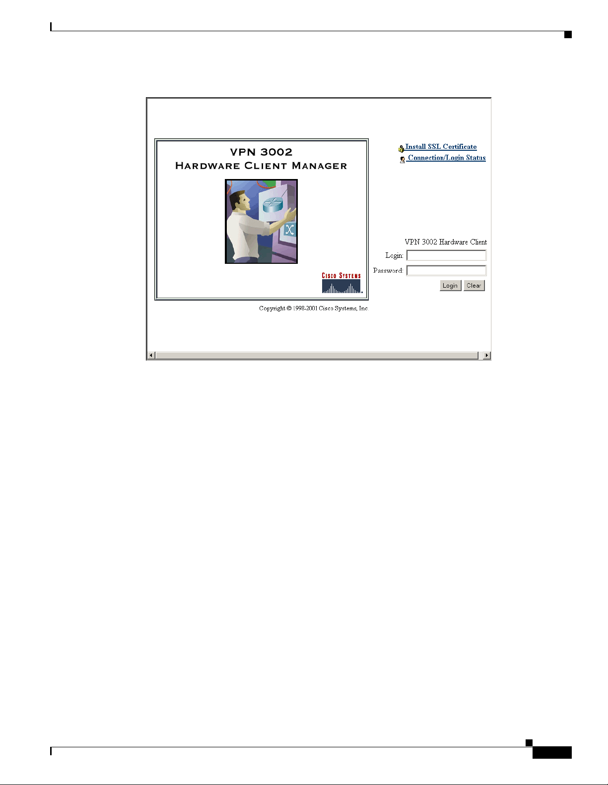
The browser d isplay s t he V PN 3 002 H a rdwa re C lie nt M ana ger lo gin scr een.
1-2
VPN 3002 Hardware Client Reference
OL-1893-01
Page 19
Chapter 1 Using th e VPN 3 00 2 H ardware Client Manager
Figure 1-1 VPN 3002 Hardware Client Manager Login Screen
Installing the SSL Certificate in Your Browser
To continue using HTTP for the whol e se ssion, sk ip to “Logging i nto the VP N 3002 Hardw are Clien t
Manager.”
Installing the SSL Certificate in Your Browser
The Manager provides th e option o f using HTTP over SSL with th e browser. SSL creates a secure
session between your brow ser (VPN 30 02 ha rdwa re c li ent) a nd the V PN Conc ent rator (se rver ). T his
protocol is known as H TTPS, and use s the htt ps:/
authenticates the server, then encrypts all data passed during the session.
HTTPS is often confu sed w ith a sim ilar pr otoc ol, S- HTT P (Se cure HT TP), whi ch e ncry pt s on ly H TTP
application-level data. SSL encrypts all data between client and server at the IP socket level, and is thus
more secure.
SSL uses digital cert ific ates for a uthent icat ion. The VPN 3 002 c reate s a se lf- signe d SSL ser ve r
certificate when it boots, and this certificate must be installed in the browser. Once the certificate is
installed, you can connect using HTTPS. You need to install the certificate from a given VPN 3002 only
once.
Managing the VPN 3002 is the same with or w ithout SSL. Manager scree ns might take slig htly longe r
to load with SSL because of encryption/decryption processing. When connected via SSL, the browser
shows a locked-padlock icon on its status bar. Both Microsoft Internet Explorer and Netscape Navigator
support SSL.
For HTTPS to work on the public interf ace, you must enable HTT PS on the VPN 30 02 through the
command-line interface or from an HTTP session on the private interface first.
/ prefix to connect to the server. The browser first
OL-1893-01
VPN 3002 Hardware Client Reference
1-3
Page 20
Installing the SSL Certificate in Your B rowser
Follow these steps to install and use the SSL certificate for the first time. We provide separate
instructions fo r Inte rnet Ex plo re r an d N e tsca pe Na viga tor w hen th ey d iverge.
Step 1 Connect to the VPN 3002 usin g HTTP as abov e.
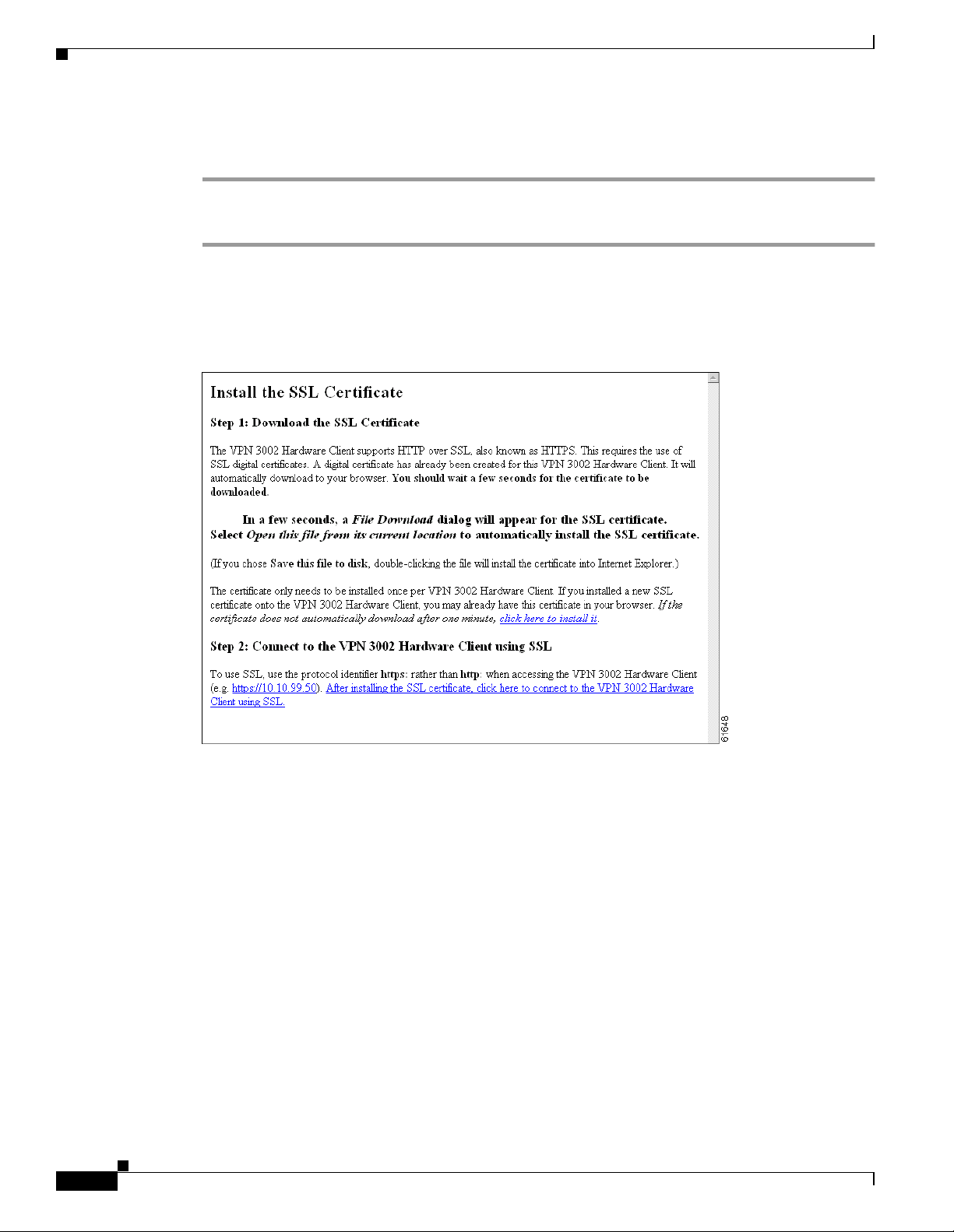
Step 2 On the login screen, click the Install SSL Certificate link.
The Manager displays the Install SSL Certificate screen and automatically begins to download and
install its SSL certificate in your browser.
Figure 1-2 Install SSL Certificate Screen
Chapter1 Using the VPN 3002 Hardware Client Manager
The installation sequence now differs depe nding on the browser. Continue below for Internet Explorer,
or skip to “Installing the SSL Certificate with Netscape.”
Installing the SSL certificate with Internet Explorer
This section describes SSL certificate installation using Microsoft Internet Explorer 5.0. (With Internet
Explorer 4.0, so me dial og boxes a re di fferen t but the pr ocess i s sim ila r.)
You need to install the SSL certificate from a given VPN 3002 only once. If you do reinstall it, the
browser repeats all these steps each time.
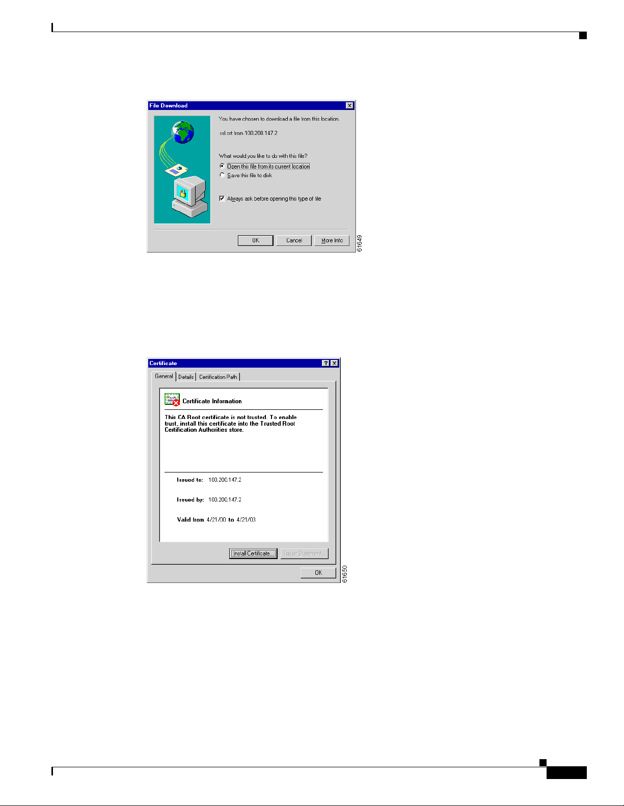
A few seconds after the VPN 3002 Hardware Client Manager SSL screen appears, Internet Explorer
displays a File Download dialog box that identif ies the certificate fi lename and source, and asks whet her
to Open or Save the certific ate. To immediately install the certificate in the b rowser, select Open. If you
Save the file, the browser prompts for a location; you must then double-click the file to install it.
VPN 3002 Hardware Client Reference
1-4
OL-1893-01
Page 21
Chapter 1 Using th e VPN 3 00 2 H ardware Client Manager
Figure 1-3 Internet Explorer File Download Dialog Box
3.
Click the Open this file from its current location radio button, then click OK.
The browser displays the Certificate dialog box with information about the certificate. You must now
install the certificate.
Installing the SSL Certificate in Your Browser
Figure 1-4 Internet Explorer Certificate Dialog Box
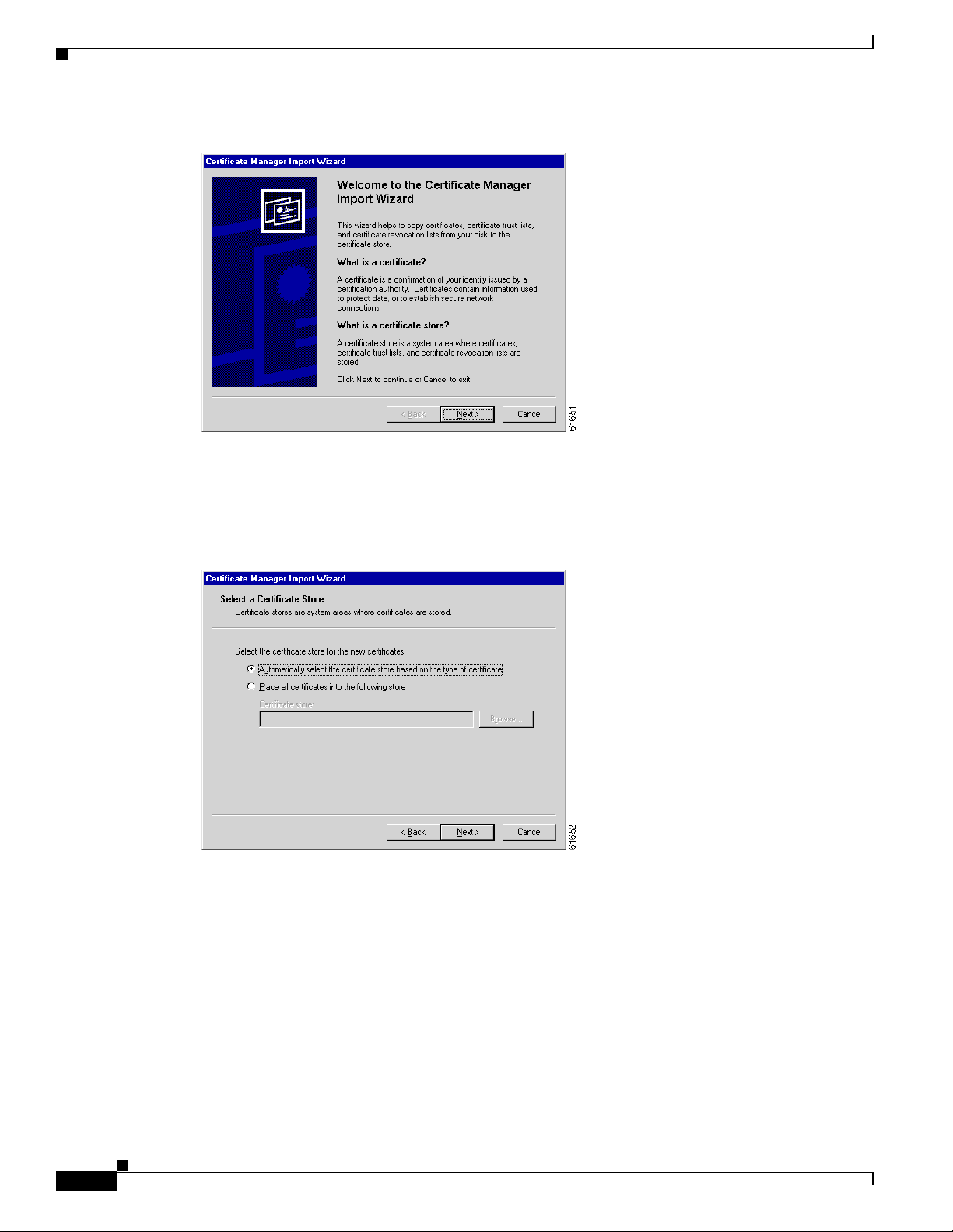
Click Install Certificate.
4.
The browser starts a wizard to install the certificate. The certificate store is where such certificates are
stored in Internet Explorer.
OL-1893-01
VPN 3002 Hardware Client Reference
1-5
Page 22
Installing the SSL Certificate in Your B rowser
Figure 1-5 Internet Explorer Certificate Manager Import Wizard Dialog Box
5.
Click Next to continue.
Chapter1 Using the VPN 3002 Hardware Client Manager
The wizard op ens the nex t dia log box aski ng yo u to sel ect a c ert ific ate stor e.
Figure 1-6 Internet Explorer Certificate Manager Import Wizard Dialog Box
6. Let the wizard Automatically select the certificate store, and click Next.
The wizard opens a dialog box to complete the installation.
1-6
VPN 3002 Hardware Client Reference
OL-1893-01
Page 23
Chapter 1 Using th e VPN 3 00 2 H ardware Client Manager
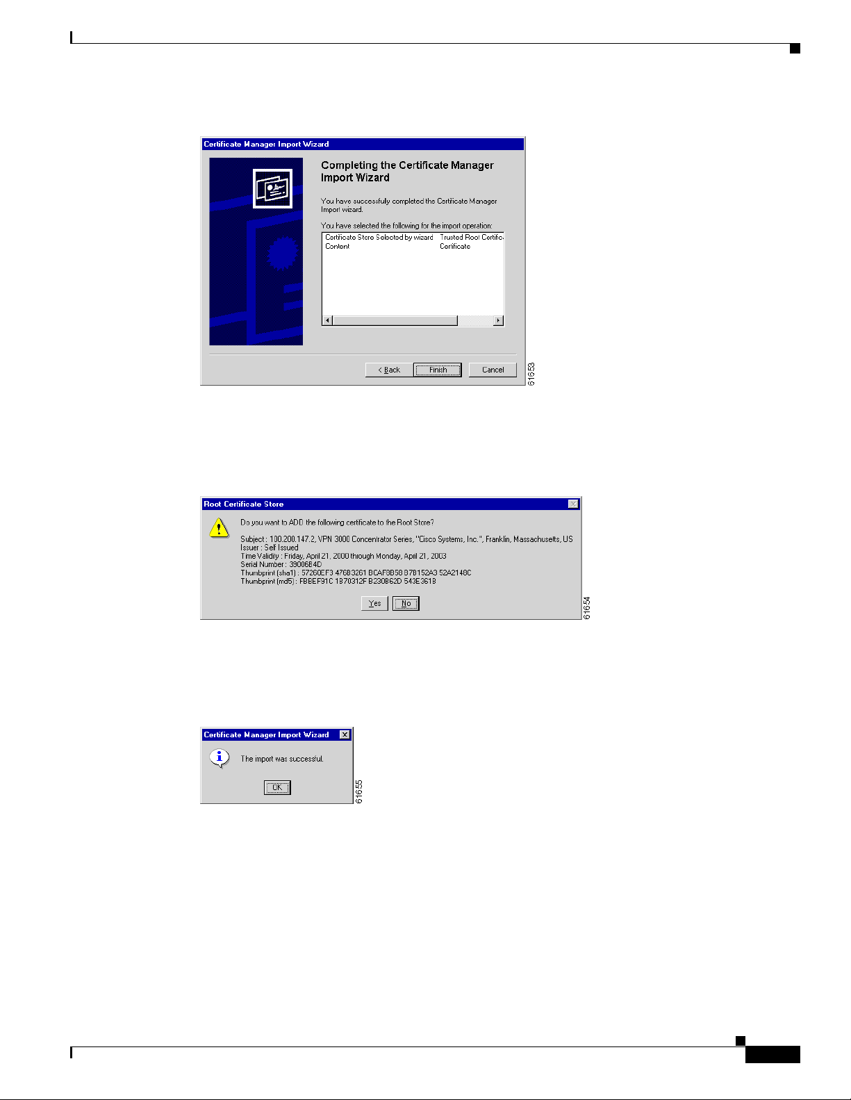
Figure 1-7 Internet Explorer Certificate Manager Import Wizard Dialog Box
7.
Click Finish.
The wizard opens the Root Certif icate St ore dialog box askin g you to confi rm the i nstalla tion.
Installing the SSL Certificate in Your Browser
Figure 1-8 Internet Explorer Root Certificate Store Dialog Box
8.
To install the certificate, click Yes. This dialog box closes, an d a final wiza rd conf irmati on dialog
box opens.
Figure 1-9 Internet Explorer Certificate Manager Import Wizard Final Dialog Box
9. Click OK to close this dialog box, and click OK on the Certificate dialog box (Figure 1- 4) to close
it.
Yo u ca n n ow c onne ct to t he V PN 3002 u sing HTTP ov er SSL ( HTTPS) .
OL-1893-01
10. On the Manager SSL screen (Figure 1-2), click the link that says After installing the SSL
certificate, click here to connect to the VPN 3002 Hardware Client using SSL.
Depending on how your brows er is confi gured, you might see a Security Al ert dialo g box.
VPN 3002 Hardware Client Reference
1-7
Page 24

Installing the SSL Certificate in Your B rowser
Figure 1-10 Internet Explorer Security Alert Dialog Box
11.
Click OK.
The VPN 3002 Hardware Clien t displays the H TTPS versi on of the Manag er login scr een.
Figure 1-11 VPN 3002 Hardware Client Manager Login Screen Using HTTPS (Internet Explorer)
Chapter1 Using the VPN 3002 Hardware Client Manager
The browser maintains the HTTPS state until you close it or access an unsecured site; in the latter case
you might see a Security Alert screen.
Proceed to Logging into the VPN 3 002 H a rdwa re Cl ie nt M ana ger to log in as usual.
Viewing Certificates with Internet Explorer
There are (at least) two ways to examine certificates stored in Internet Explorer.
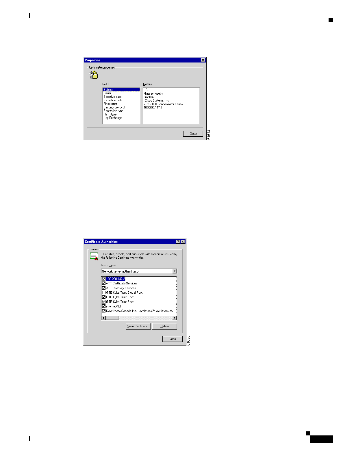
First, note the padlock icon on the bro wser statu s bar in Figure 1-11. If you double-click the icon, th e
browser opens a Certificate Properties screen showing details of the specific certificate in use.
VPN 3002 Hardware Client Reference
1-8
OL-1893-01
Page 25
Chapter 1 Using th e VPN 3 00 2 H ardware Client Manager
Figure 1-12 Internet Explorer 4.0 Certificate Properties Screen
Click any of the Field items to see Details. Click Close when finished.
Second, you can v iew al l the certif icates that are st ored in In ternet E xplo rer 4 .0. C lick the bro wser View
menu and select Internet Options. Click the Content tab, then click Authorities in the Certificates
section.
In Internet Explore r 5.0, click the browser Tools menu and select Internet Options. Click the Content
tab, then click Certificates in the Certificates section. On the Certificate Manager, click the
Root Certification Authorities tab.
Installing the SSL Certificate in Your Browser
Trusted
The VPN 3002 Hardware Cli ent SSL certif icate na me is its Eth ernet 1 (pri vate) IP addre ss.
Figure 1-13 Internet Explorer 4.0 Certificate Authorities List
Select a certificate , th en c lick View Certificate. The browser displays the Cer tif ica te Prop er ties scr een,
as in Figure 1-12 above.
Installing the SSL Certificate with Netscape
This section describes SSL certificate installation using Netscape Navigator / Communicator 4.5.
OL-1893-01
VPN 3002 Hardware Client Reference
1-9
Page 26
Installing the SSL Certificate in Your B rowser
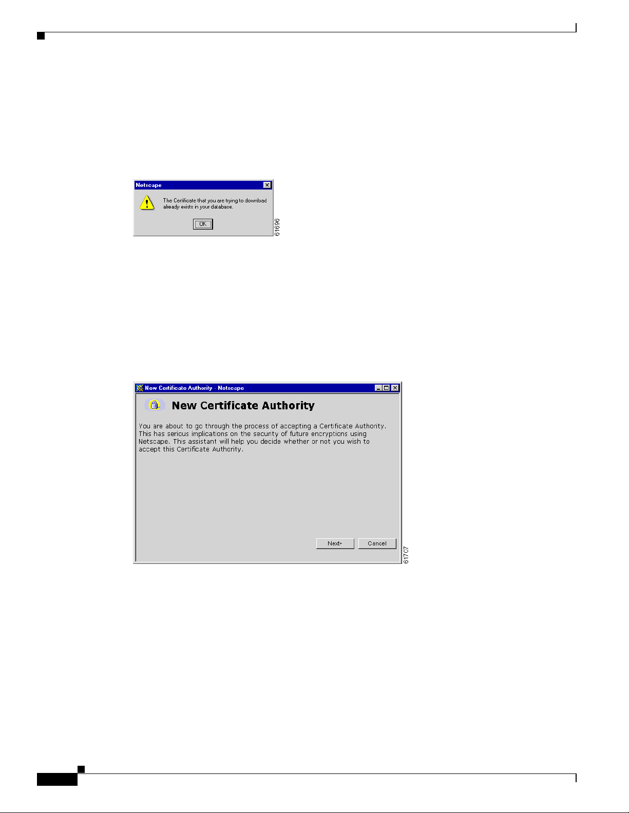
Reinstallation
You need to install the SSL certificate from a given VPN 3002 only once. If you try to reinstall it,
Netscape displays the note in Figure 1-14. Click OK and just conne ct to t he V PN 300 2 usi ng SSL ( see
Step 7 in this section.
Figure 1-14 Netscape Reinstallation Note
First-time Installation
The instructions below follow from Step 2 in “Installing the SSL Certificate in Your Browser,” and
describe first-time certificate installation.
A few seconds after the VPN 3002 Hardware Client Manager SSL screen appears, Netscape displays a
New Certificate Authority screen.
Chapter1 Using the VPN 3002 Hardware Client Manager
Figure 1-15 Netscape New Certificate Authority Screen 1
Click Next> to proceed.
1.
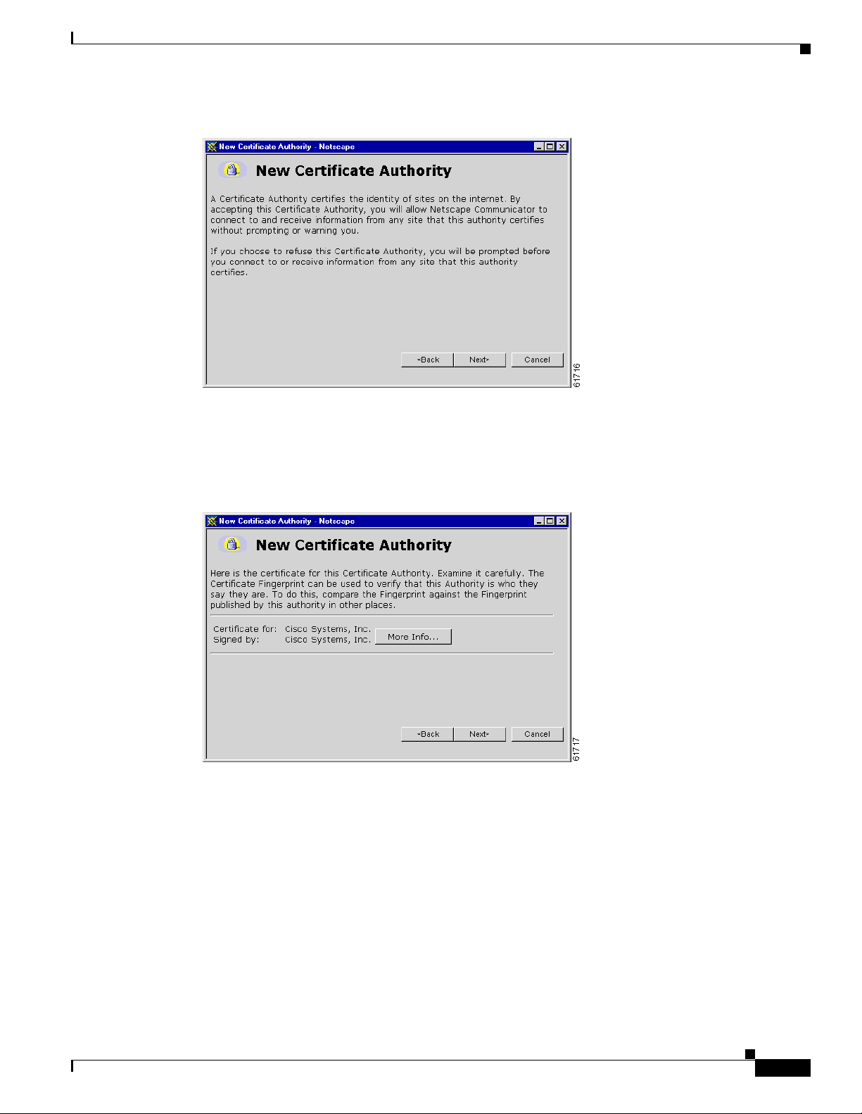
Netscape displays the next Ne w Certif icate Au thority screen, w hich furthe r explai ns the process.
1-10
VPN 3002 Hardware Client Reference
OL-1893-01
Page 27
Chapter 1 Using th e VPN 3 00 2 H ardware Client Manager
Figure 1-16 Netscape New Certificate Authority Screen 2
2.
Click Next> to proceed.
Netscape displays the next New Certificate Authority screen, which lets you examine details of the VPN
3002 Hardware Client SSL cer tificate.
Installing the SSL Certificate in Your Browser
Figure 1-17 Netscape New Certificate Authority Screen 3
3.
Click Next> to proceed.
Netscape displays the next New Certificate Authority screen, with choices for using the certificate. No
choices are checked by default .
OL-1893-01
VPN 3002 Hardware Client Reference
1-11
Page 28
Installing the SSL Certificate in Your B rowser
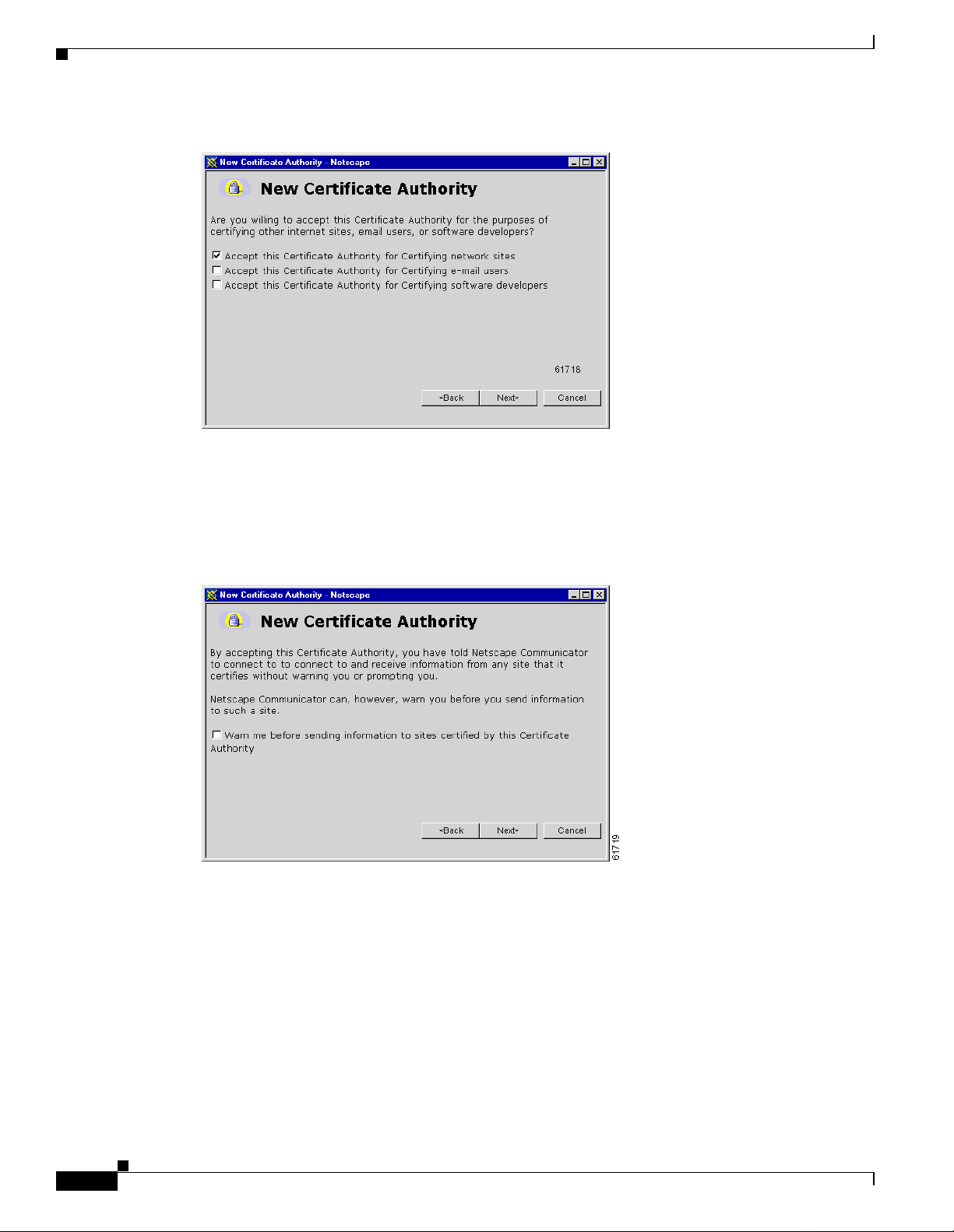
Figure 1-18 Netscape New Certificate Authority Screen 4
4.
You must check at least the first box, Accept this Certificate Authority for Certifying network
sites. Click Next> to proceed.
Chapter1 Using the VPN 3002 Hardware Client Manager
Netscape displays the next New Cer tifica te Author ity scree n, whic h lets you choo se to have the browser
warn you about sending data t o the VPN 30 02.
Figure 1-19 Netscape New Certificate Authority Screen 5
5. Checking the box is op tio na l. Doi ng so me an s tha t you ge t a war ning wh enev er yo u a pply setti ng s
on a Manager screen, so it is probably less intrusive to manage the VPN 3002 without those
warnings. Click Next> to proceed.
1-12
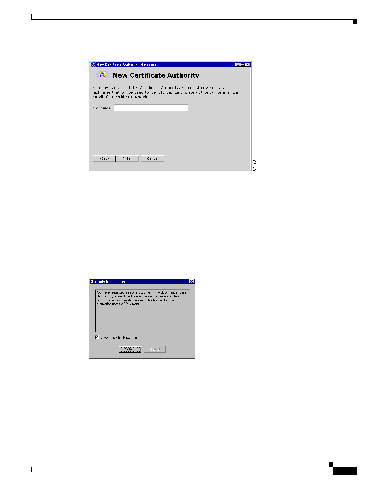
Netscape displays the final New Certificate Authority screen, which asks you to name the certificate.
VPN 3002 Hardware Client Reference
OL-1893-01
Page 29
Chapter 1 Using th e VPN 3 00 2 H ardware Client Manager
Figure 1-20 Netscape New Certificate Authority Screen 6
6.
In the Nickname field, enter a descriptive name for this certificate. “Nickname” is something of a
misnomer. We suggest you use a cl ear ly d escrip tive name su ch a s
This name appears in the list of installed certificates; see “Viewing Certificates with Netscape,”
below.
Installing the SSL Certificate in Your Browser
Cisco VPN 3002 10.10.147.2.
Click Finish.
Yo u ca n n ow c onne ct to t he V PN 3002 u sing HTTP ov er SSL ( HTTPS) .
7. On the Manager SSL screen (Figure 1-2), click the link that says After installing the SSL
certificate, click here to connect to the VPN 3002 Hardware Client using SSL.
Depending on how your brows er is confi gured, you might see a Security In format ion Alert dial og box.
Figure 1-21 Netscape Security Information Alert Dialog Box
Click Continue.
8.
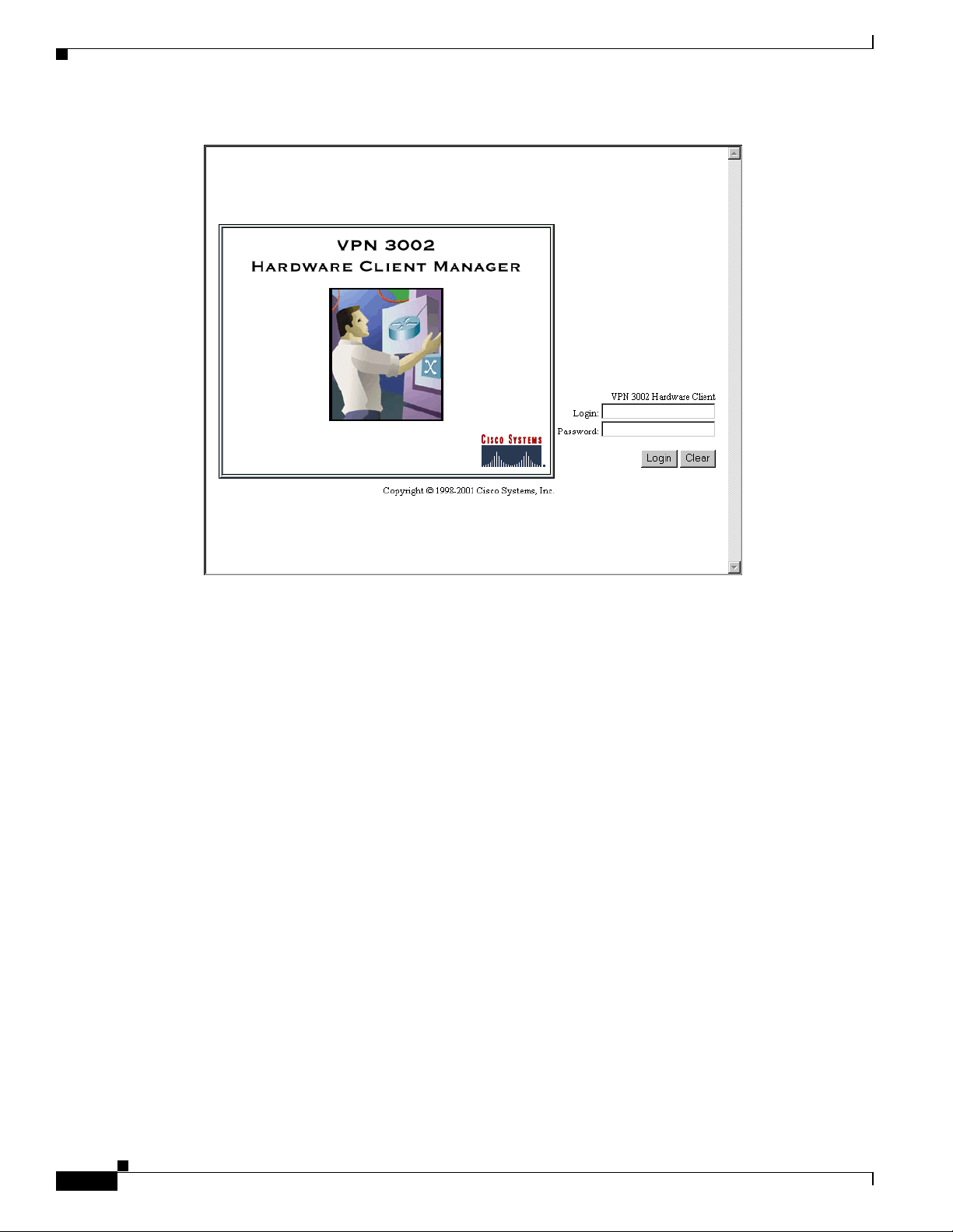
The VPN 3002 displays the HTT PS version of the M anager login screen.
OL-1893-01
VPN 3002 Hardware Client Reference
1-13
Page 30
Installing the SSL Certificate in Your B rowser
Figure 1-22 VPN 3002 Hardware Client Manager Login Screen Using HTTPS (Netscape)
Chapter1 Using the VPN 3002 Hardware Client Manager
The browser maintains the HTTPS state until you close it or access an unsecured site; in the latter case,
you might see a Se c urity In for mat ion Ale rt dial og b ox.
Proceed to the section, “Logging into the VPN 300 2 Hardw are Clien t Manager,” to log in as usual.
Viewing Certificates with Netscape
There are (at l e ast ) two w ay s to exa m in e c er tif i cat es s tor ed in Ne t sca pe N av ig ato r / Co mm uni cat o r 4.5 .
First, note the locked-padlock icon on the bottom status bar in Figure 1-22. If you c lick the ic on,
Netscape opens a Secu ri ty Info w ind ow. (You can also open thi s wi nd ow b y c lick ing Sec urity on th e
Navigator Toolbar at the top of the Netscape window.)
1-14
VPN 3002 Hardware Client Reference
OL-1893-01
Page 31

Chapter 1 Using th e VPN 3 00 2 H ardware Client Manager
Figure 1-23 Netscape Security Info Window
Installing the SSL Certificate in Your Browser
Click View Certificate to see details of the specific certificate in use.
Figure 1-24 Netscape View Certificate Screen
Click OK when finished.
Second, you can v iew all the cert ificates th at are st ored in Netsca pe. On the Securit y Inf o window, select
Certificates, then Signers. The “nickname” you entered in Step 6 in the section, “First-time
Installation,” identifies the VPN 3002 Hardware Client SSL certificate.
OL-1893-01
VPN 3002 Hardware Client Reference
1-15
Page 32

Connecting to the VPN 3002 Using HTT P S
Figure 1-25 Netscape Certificates Signers List
Chapter1 Using the VPN 3002 Hardware Client Manager
Select a certificate, then click Edit, Verify, or Delete. Click OK when finished.
Connecting to the VPN 3002 Using HTTPS
When you have installed the SSL certificate in the browser, you can connect directly using HTTPS.
Step 1 Bring up the browser.
Step 2 In the browser Address or Location field, enter https:// plus the VPN 3002 private interface IP address;
for example, https://10.10.147.2.
The browser disp lay s th e V PN 3 002 H ardw are C lient Ma nage r HTTPS logi n sc reen .
A locked-padlock i con on the brow ser stat us bar indi cate s an HTT PS sessi on . Also, th is login sc reen
does not include the Install SSL Certifi cate link.
Configuring HTTP, HTTPS, and SSL Parameters
HTTP, HTTPS, and SSL are enabled by default on the VPN 3002, and they are configured with
recommended parameters that should suit most administration tasks and security requirements.
1-16
To configure HTTP and HTTPS parame ters , s ee t he Conf igur ati on | Syst em | Mana geme nt Protoc ols |
HTTP/HTTPS screen.
To configure SSL parameters, see the Configuration | System | Management Protocols | SSL screen.
VPN 3002 Hardware Client Reference
OL-1893-01
Page 33

Chapter 1 Using th e VPN 3 00 2 H ardware Client Manager
Figure 1-26 VPN Hardware Client Manager HTTPS Login Screen
Logging into the VPN 3002 Hardware Client Manager
Logging into the VPN 3002 Hardware Client Manage r
Logging into the VP N 3 002 Har dwa re Cl ie nt M ana ger i s the same fo r bo th typ es of c onnec ti ons,
cleartext HTTP or secure HTTPS.
Entries are case-sensitive. With Microsoft Internet Explorer, you can select the Tab key to move from
field to field; ot h er br owse rs m ight wo rk different ly. If you make a m istake , cl ic k th e Clea r button a nd
start over.
The following e ntri es a re the fa cto ry-supp l ied de fa ult e ntr ies. If you ha ve c hange d the m, use your
entries.
Step 1 Click in the Login field and type admin. (Do not press E nter.)
Step 2 Click in the Password field and type admin. ( The fiel d show s ** *** .)
Step 3 Click the Login button.
The Manager displays the main welc ome scr een (Figure 1-27).
OL-1893-01
VPN 3002 Hardware Client Reference
1-17
Page 34

Logging into the VPN 3002 Hardware Client Manager
Figure 1-27 Manager Main Welcome Screen
Chapter1 Using the VPN 3002 Hardware Client Manager
1-18
From here you can navigat e the Ma nager usi ng eith er the ta ble of con ten ts in the lef t fram e, or the
Manager toolbar in th e top fram e.
VPN 3002 Hardware Client Reference
OL-1893-01
Page 35

Chapter 1 Using th e VPN 3 00 2 H ardware Client Manager
Interactive Hardware Client and Individual User Authentication
Interactive Hardware Client and Individual Use r Authentica tion
Interactive hardwa re cli ent and indi vidual use r auth entica tion prov ide secu rity by requirin g manua l
entry of usernames and pa sswords prior to co nnection . You configure these features on the V PN
Concentrator to w hich this VPN 300 2 con ne cts, a nd the VP N C oncen t rato r push es the pol icies yo u s et
to the VPN 3002. You can use interactive hardware client au the nticat ion and ind ividua l user
authentication in combination or separately.
For complete configuration information refer to the section on the Hardware Client tab in the User
Management chap ter of the VP N 3000 Se rie s Co ncen tra tor R ef erence Volume 1: Configuration.
Interactive Hardware Client Authentication
When you enable int era cti ve har dwa re cl ient au then t icat ion, t he V PN 3002 do es not use a s ave d
username and password. Instead, to connect you must manually enter a valid username and password for
the VPN 3002 when prompted. When the VPN 3002 initiates the tunnel, it sends the username and
password to the VPN Concentrator to which it connects. The VPN Concentrator facilitates
authentication, on either the internal or an external server. If the username and password are valid, the
tunnel is established.
Individual User Authentication
Individual user authentication protects the central site from access by unauthorized persons on the same
LAN as the VPN 3002.
When you enable individual user authentication, each user that connects through a VPN 3002 must open
a web browser and manually enter a valid username and password to access the network behind the VPN
Concentrator, even though the tunn el alrea dy exi sts.
• If you direct the br owser to a sit e on t he r em ote net work b ehin d t he VPN Conce ntra tor, the VPN
3002 directs the browser to the prop er pages for login. Whe n you succe ssfully log in, t he browse r
displays the page you origin ally en tered .
• You can also log in by directing the browser to the private interface of the VPN 3002 html
interface.You do this by entering the IP address of the private interface in the browser Location or
Address field. Th e br owser d ispl ays the lo gin s cr een for the VPN 300 2. Cl ick the C onnec t/ Logi n
Status button to authenticate.
Note You cannot use the command-line interface to login if user authentication is enabled. You must use
a browser.
Logging In With Interactive Hardware Client and Individual User Authentication
OL-1893-01
You access the interactive hardware client authentication and individual user authentication login
screens from the VPN 3002 Hardware Client Manager login screen. The sequence in the login examp le
that follows assumes that both interactive hardware client authentication and individual user
authenticatio n are requi red for this VP N 3002 to co nnect.
VPN 3002 Hardware Client Reference
1-19
Page 36

Logging In With Interactive Hardware Client and Individual User Authentication
Figure 1-28 VPN 3002 Hardware Client Manager Login Screen
Chapter1 Using the VPN 3002 Hardware Client Manager
Step 1 Click the Connection Login Status button.
The Connection/Login Status screen displays
.
Step 1 Click the Connect Now button.
Figure 1-29 Connection Login Status Screen
The VPN 3002 Interacti ve Auth entica tion scr een displa ys.
1-20
VPN 3002 Hardware Client Reference
OL-1893-01
Page 37

Chapter 1 Using th e VPN 3 00 2 H ardware Client Manager
Figure 1-30 VPN 3002 Interactive Authentication Screen
Step 1 Enter the user name and pa sswor d f or t he V PN 3002 .
Step 2 Click Connect.
If you have entered the valid use rname an d password , the Connect Login Status s creen displa ys the
message that the V PN 3002 i s co nnec ted. Ne xt y ou au the ntica te t he use r.
Logging In With Interactive Hardware Client and Individual User Authentication
Figure 1-31 Connection Login Status Screen
Step 1 To authenticate an individual user, click Log In Now.
The Individual User Aut hentica tion scree n displays.
OL-1893-01
VPN 3002 Hardware Client Reference
1-21
Page 38

Logging In With Interactive Hardware Client and Individual User Authentication
Figure 1-32 Individual User Authentication Screen
Step 1 Enter the user name a nd pa sswor d f or thi s VPN 300 2 u ser.
Step 2 Click Login. If the userna me an d pa sswor d yo u en ter ed a re valid , th e Con nection/Login Status window
displays information ab out the conne ction.
Chapter1 Using the VPN 3002 Hardware Client Manager
Figure 1-33 Connection/Login Status Scr e en
The user behind the VPN 3002 is connecte d to the VPN C oncentra tor at the central si te.
Click Go back to the VPN 3002 administrative login page to return to the VPN 3002 Hardware Client
Manager login scre en and a cce ss oth er f eat ures an d f unct ions of t he V PN 3002 .
1-22
VPN 3002 Hardware Client Reference
OL-1893-01
Page 39

Chapter 1 Using th e VPN 3 00 2 H ardware Client Manager
Understanding the VPN 3002 Hardware Client Manager Window
Understanding the VPN 3002 Hardware Cl ient Manager Window
The VPN 3002 H ardw are Cl ient Ma nage r wi nd ow on you r b rowse r con sis ts of th ree fram es —top, left,
and main—and it provides helpful messages and tips as you move the mouse pointer over window items.
The title bar and status bar also prov ide usefu l inform ation
Figure 1-34 VPN 3002 Hardware Client Manager Window.
OL-1893-01
VPN 3002 Hardware Client Reference
1-23
Page 40

Understanding the VPN 3002 Hardware Client Manager Window
Title bar The title bar at the top of the browser window inc lude s the VPN 3 0 02
Status bar The status bar at th e bott om of t he br ow ser wind o w di spla ys Mana ge r
Mouse pointer and tips As you move the mouse pointer over an active area, the pointer
Chapter1 Using the VPN 3002 Hardware Client Manager
device name or I P a dd ress i n br ac ket s, for exa mp le, [10. 10. 4.6].
activity and explanatory messages for some items.
changes shape and icon s change col or. A description also appea rs in
the status bar area. If you momentarily rest the pointer on an icon, a
descriptive tip appears for that icon.
Top frame
(Manager toolbar)
The Manager toolbar in the top fram e provides qui ck acce ss to
Manager features. These include the following icons:
Click the Main tab to go to the main Manager screen, and to close all
subordinate sections and titles in the left frame.
Click the Help tab to open context-sensitive online help. Help opens
in a separate browser window that yo can move or resize as you want.
Close the help wi ndow whe n you are fin ishe d.
Click the Support tab to open a Manager screen with links to Cisco
support and documentation re sources.
Click the Logout tab to log out of the Manager and return to the login
screen.
Logged in: [use rna me] The administrator username you used to log in to this Manager session.
Click the Configuration tab to go to the main Configuratio n screen, to
open the first le vel of sub or dina te Conf igur ati on page s in the le ft
frame if they are not already open, and to close any open
Administration or Monitoring pages in the left frame.
1-24
Click the Administration tab to go to th e main Administr at ion scr een,
to open the first level of subordinate Administration pages in the left
frame if they are not already open, and to close any open
Configuration or Moni toring page s in the left fra me.
Click the Monitoring tab to g o to the ma in Moni toring scr een, to open
the first level of subordin ate Monitorin g pages in the le ft frame if th ey
are not already open, and to close any open Configuration or
Administration pages in the left frame.
VPN 3002 Hardware Client Reference
OL-1893-01
Page 41

Chapter 1 Using th e VPN 3 00 2 H ardware Client Manager
Save Click the Save icon to save the active configuration and make it the
Save Needed This reminder indi cates that yo have chang ed the active config uration.
Refresh Cli ck the Ref resh icon to refresh (update ) the scre en conte nts on
Understanding the VPN 3002 Hardware Client Manager Window
boot configuration. In this state, the reminder indicates that the acti ve
configuration is the sam e a s t he bo ot c onf igura tion, bu t yo u c an sa ve
it anyway. When you change the configuration, the reminder changes
to Save Needed.
Click the Save Needed icon to save the active configuration and make
it the boot configuration. As you make configuration entries, they take
effect immediately and are included in the active, or running,
configuration. Howe ver, if you reboot the VPN 3002 wit hout saving
the active configuration, and configuration cha n ge s are lo s t. C licki n g
on this reminder saves the activ e conf iguration as t he boot
configuration an d restore s the Save r emi nder.
screens where it appears (mostly in the Monito ri ng secti on) . Th e d ate
and time above th is remin der in dicat e whe n the s creen was last
updated.
Reset Click the Reset icon to reset, or start anew, the screen contents on
screens where it appears (mostly in the Monitoring section).
Restore Click the Restore icon to restore the screen contents to their status
prior to when you last clicked on the Reset ico n.
Click the Cisco Syste ms logo to open a br owser and go to the
Cisco.com web site, www.cisco.com
Left frame
(Table of Contents)
On Manager screens, th e left fr ame pr ovides a table of cont ents . The
table of contents uses th e familia r Windows Explorer met aphor of
collapsed and expande d entries.
Main section titles
(Configuration,
Click on a title to open subordinate sections and titles, and to go to that
Manager screen in the main frame.
Administration,
Monitoring
Closed or collapsed Click the closed/collapsed ic on to open subordinate sections and titles.
Clicking on this icon does not change the screen in the main frame.
OL-1893-01
VPN 3002 Hardware Client Reference
1-25
Page 42

Understanding the VPN 3002 Hardware Client Manager Window
Open or expanded Click the open/expanded icon to close subordinate sections and titles.
Chapter1 Using the VPN 3002 Hardware Client Manager
Clicking on this icon does not change the screen in the main frame.
Main frame
(Manager screen)
The main frame displays the current VPN 3002 Hardware Client
Manager screen.
Many screens includ e a bul let l ist o f link s and de script ion s of
subordinate sections and titles. you can click a link to go to that
Manager screen, an d o pe n s ubordi nat e se cti ons and titl es i n the ta ble
of contents.
1-26
VPN 3002 Hardware Client Reference
OL-1893-01
Page 43

Chapter 1 Using th e VPN 3 00 2 H ardware Client Manager
Organization of the VPN 3002 Hardware Client Manager
Organization of the VPN 3002 Hardware Client Manager
The VPN 3002 Hardware Cli ent Manag er consists of t hree major sections and many subse ctions:
• Configuration: setting all the parameters for the VPN 3002 that govern its use and functionality as
a VPN device:
–
Quick Configuration: supplying th e minim al parame ters neede d to make the VPN 3002
operational.
–
Interfaces: E ther net para m ete rs.
–
System: parameters for system-wide functions such as server access, IPSec tunneling protocol,
built-in management servers, event handling, and system identification.
–
Policy Management : ena bli ng PAT (Port A ddres s Translation).
• Administration: ma nagi ng hig he r leve l f unc tion s th at keep t he V PN 30 02 ope rat iona l a nd secu re ,
such as who is allowed to configu re the syst em, wha t software runs on it, an d managing i ts
configuration files and digital certificates.
• Monitoring: viewin g rout ing table s, event lo gs, system L EDs a nd st atus, and d ata on user s ession s.
This manual covers all these topics. For Quick Configuration, refer to the VPN 3002 Hardware Client
Getting Started guide.
OL-1893-01
VPN 3002 Hardware Client Reference
1-27
Page 44

Chapter1 Using the VPN 3002 Hardware Client Manager
Navigating the VPN 3002 Hardware Client Manager
Navigating the VPN 3002 Hardware Client Manager
Your primary tool for navigating the VPN 3002 Hardware Client Manager is the table of contents in the
left frame. Figure 1-35 shows all its entries, completely expanded. (The figure shows the frame in
multiple columns, but the actual frame is a single column. Use the scroll controls to move up and down
the frame.)
Figure 1-35 Manager Table of Contents
1-28
VPN 3002 Hardware Client Reference
OL-1893-01
Page 45

Configuration
Configuring the VPN 3002 means setting all the parameters that govern its use and functionality as a
VPN device.
Cisco supplies default parameters that cover typical installations and uses; after you supply minimal
parameters in Quick Configuration, the system is operat ional. But to tailo r the system to your ne eds, and
to provide an appropriate level of system security, you can configure the system in detail.
Configuration
This section of the Ma na ger let s you c onf igur e all V PN 3002 f ea tur es and f unc tions.
• Quick Configuration: the minimal parameters needed to mak e the VPN 3002 operational. For more
information, u se
available only onl ine.
online Help, or see the VPN 3002 Hardware Client Getting Started manual,
CHAPTER
2
• Interfaces: parameters specific to the private and public interfaces.
• System: parameters for system-w ide fun ctions : server acc ess, IPSe c, IP rout ing, buil t-in
management servers, system events, and system identification.
• Policy Management: enabling or disab lin g Pr otoc ol Ad dre ss Translation (PAT).
Figure 2-1 Configuration Screen
See the appropriate chapter in this manual for each section of the Manager. Online help is available for
all sections.
OL-1893-01
VPN 3002 Hardware Client Reference
2-1
Page 46

Configuration
Chapter 2 Configuration
2-2
VPN 3002 Hardware Client Reference
OL-1893-01
Page 47

Interfaces
This section of the VPN 3002 Hardware Client Manager applies functions that are interface-specific,
rather than system-wide.
Y ou configure two network interfaces for the VPN 3002 to operate as a VPN device: the private interface
and the public interface. If you used Quick Configuration as described in the VPN 3002 Hardware Client
Getting Started manual, the system supplied many default parameters for the interfaces. Here you can
configure them explicitly.
The VPN 3002 includes some IP routing functions: static routes, DHCP , and PPPoE. You configure static
routes, the default gateway, and DHCP in the IP Routing section; see the Configuration | System | IP
Routing screens. PPPoE requires no further configuration than supplying a us ername and password in
the Public Interface parameter.
Configuration | Interfaces
CHAPTER
3
This section lets you configure the private and public interfaces.
• Private is the int er face t o yo ur pr iv ate n etwor k ( int er nal LAN ).
• Public is the interface to the public network.
Configuring an E thernet interface includes supplying an IP address and subnet mask, and setting speed
and transmission mode.
Note Interface settin gs take ef fect as soon as you ap ply th em. I f the sy stem is in activ e use, c hanges might
affect tunnel traffic.
The table on the Configuration | Interfaces screen shows all installed interfaces and their status.
OL-1893-01
VPN 3002 Hardware Client Reference
3-1
Page 48

Configuration | Interfaces
Chapter3 Interfaces
Figure 3-1 VPN 3002 Configuration | Interfaces Screen
To configure a modu le, eith er click t he appropr iate link i n the statu s table; or use the mou se poin ter to
select the module on the back-panel image, and click anywhere in the highlighted area.
Interface
The VPN 3002 interface installed in the system. To configure an interface, click the appropriate link.
Ethernet 1 (Private), Ethernet 2 (Public)
T o con figure Et hernet i nterf ace par ameters , click th e appr opriate highligh ted link in the tab le or click in
a highlighted module on the back -panel image. See Configu rati on | Interfa ces | Privat e/Publ ic.
DNS Server (s)
To configure DNS Server(s), click the highlighted link in the table. See Configuration | System |
Servers | DNS.
DNS Domain Name
To configure DNS Server(s), click the highlighted link in the table. See Configuration | System |
Servers | DNS.
3-2
VPN 3002 Hardware Client Reference
OL-1893-01
Page 49

Chapter 3 Interfaces
Status
IP Address
Configuration | Interfaces
The operational status of this interface:
• UP (green) = Configured, enabled, and operational; ready to pass data traffic.
• DOWN (red) Configured but disabled or disconnec ted.
• Testing = In test mode; no regular data traffic can pass.
• Dormant (red) = Configured and enabled but waiting for an external action, such as an incoming
connection.
• Not Present (red) = Missi ng hardw are comp onents.
• Lower Layer Down (red) = Not operational because a lower-layer interface is down.
• Unknown (red) = Not configured or not able to determine status.
• Not Configured = Present but not configur ed.
• Waiting for DHCP/PPPoE = Wa iting for DHCP or PPPo E to assign an IP add ress.
Subnet Mask
MAC Address
Default Gateway
The IP address configured on this interface.
The subnet mask config ured on th is interf ace .
This is the unique hardware MAC (Media Access Control) address for this interface, displayed in 6-byte
hexadecimal nota tion. You cannot change this a ddress.
The IP routing subsystem routes data packets fir st using sta tic routes , then the de fault gat eway. If you
do not specify a default gate way, the system drops packets it cannot ot herwis e route.
To configure a default gateway, click the appropriate highlighted link in the table or click in a
highlighted module o n th e back -pa nel im ag e. Se e Co nfi gura tio n | Sy stem | IP Rou ting | D efa ult
Gateways.
OL-1893-01
VPN 3002 Hardware Client Reference
3-3
Page 50

Configuration | Interfaces | Priva te
Configuration | Interfaces | Private
This screen lets you configure p aram ete rs f or th e pr iv ate i nt erfac e. It d isplay s the c ur ren t pa rame ter s, if
any.
Figure 3-2 Configuration | Interfaces | Private Screen
Chapter3 Interfaces
Caution If you modify any parameters of the private interface that you are currently using to connect to the
VPN 3002, you will break the connection, and you will have to restart the Manager from the login
screen.
Disabled
To make the interface offline, click Disabled. This state lets you retain or change its configuration
parameters.
If the interface is configured but disabled (offline), the appropriate Ethernet Link Status LED blinks
green on the VPN 3002 front panel.
Static IP Addressing
To change the IP address of the private interface, click Static IP Addressing.
IP Address
Enter the IP address for this interface, using dotted decimal notation (for example, 192.168.12.34). Note
that 0.0.0.0 is n ot a ll owed . Be sur e no oth er devi ce is u si ng th is a ddr es s on the n etw or k.
3-4
VPN 3002 Hardware Client Reference
OL-1893-01
Page 51

Chapter 3 Interfaces
Subnet Mask
MAC Address
Speed
Configuration | Interfaces | Private
Enter the subnet mask for this interface, using dotted decimal notation (for example 255.255.255.0). The
Manager automatically supplies a standard subnet mask appropr iate for the IP address you just enter ed.
For example, the IP address 192.1 68.12.34 is a Class C add ress, and the st andard sub net mask is
255.255.255.0. You can accept this entry or change it. Note that 0.0.0.0 is not allowe d.
This is the unique hardware MAC (Media Access Control) address for this interface, displayed in 6-byte
hexadecimal nota tion. You cannot change this a ddress.
click the drop-down menu bu tton and select the inte rface spee d:
• 10 Mbps = Fix the speed at 10 megabits per sec ond (10B ase-T net works) .
• 100 Mbps = Fix the spee d at 100 me gabi ts p er se c ond (1 00B ase -T n etwor ks) .
Duplex
Apply/Cancel
• 10/100 auto = Let the VPN 3002 automatically detect and set the ap propriate speed, either 10 or 100
Mbps (default). Be sure that the port on the active network device (hub, switch, router, etc.) to which
you connect this interface is also set to automatically negotiate the speed. Otherwise, select the
appropriate fixed spe ed.
click the drop-down menu bu tton and select the inter face tr ansmissi on mode:
• Auto = Let the VPN 3002 automatically detect and set the appropriate transmission mode, either
full or half duplex (default) . Be sure tha t the por t on th e ac tiv e netwo rk d evi ce (hub, switch , ro uter,
etc.) to which you connect this interf ace is also set to automatically neg otiate the transmission mode.
Otherwise, select the appropriate fixed mode.
• Full-Duplex = Fix the transmission mode as full duplex: transmits and receives at the same time.
• Half-Duplex = Fix the transmission mode as half duplex: transmits or receives, but not at th e same
time.
To apply your settings to the system and include them in the active configuration, click Apply. The
Manager returns t o t he C onf ig urat ion | Inte rfac es scre en .
Reminder:
OL-1893-01
To save the active configuration and make it the boot configuration, click the Save Needed icon at the
top of the Manager window.
To discard your settings, click Cancel. The Manager returns to the Configuration | Interfaces screen.
VPN 3002 Hardware Client Reference
3-5
Page 52

Configuration | Interfaces | Publi c
Configuration | Interfaces | Public
This screen lets you select a connection method—DHCP, PPPoE, or static IP addressing—for the public
interface. It also allows you to disable the public interface.
Figure 3-3 Configuration | Interfaces | Public Screen
Chapter3 Interfaces
Disabled
DHCP Client
PPPoE Client
VPN 3002 Hardware Client Reference
3-6
To make the interface offline, click Disabled. This state lets you retain or change its configuration
parameters.
click this radio button if you want to obtain the IP address and subnet mask for this interface via DHCP.
If you click this button, you do not make entries in the IP address and subnet mask parameters that
follow.
click this radio button if you want to connect using PPPoE. If you select PPPoE, you do not make entries
in the static IP addressing parameters that follow.
OL-1893-01
Page 53

Chapter 3 Interfaces
PPPoE User Name
If you have selected PPPoE, enter a valid PPPoE username.
PPPoE Password
If you have selected PPPoE, enter the PPPoE password for the username you entered above.
Verify PPPoE Password
If you have selected PPPoE, enter the PPPoE password again to verify it.
Static IP Addressing
click this radio bu tto n i f yo u want to u se a stati c I P addr ess.
IP Address
Configuration | Interfaces | Public
Subnet Mask
MAC Address
Speed
If you are using static IP addressing, enter the IP address for this interface, using dotted decimal nota tion
(for example, 192.16 8.12. 34). No te that 0.0.0 .0 is not allowed . Be sure no other de vice is using this
address on the network.
If you are using static IP addressing, enter the subnet mask for this interface, using dotted decimal
notation (for ex am ple, 2 55.25 5.2 55. 0). T he Ma nage r au toma tica lly su ppl ies a st anda rd su bnet mask
appropriate for the IP addre ss yo u just entere d. For e xampl e, the IP ad dress 19 2.1 68. 12.34 is a Cla ss C
address, and the stan dard su bnet m ask is 255.25 5.255.0. You can accept this entry or cha nge it. Note that
0.0.0.0 is not allowed.
This is the unique hardware MAC (Media Access Control) address for this interface, displayed in 6-byte
hexadecimal nota tion. You cannot change this a ddress.
If you are using st atic IP addr e ssing, cl ick the drop- dow n me nu b utt on an d se le ct the in terfa ce spe ed:
• 10 Mbps = Fix the speed at 10 m eg abits pe r secon d ( 10B ase-T netw orks) .
• 100 Mbps = Fix the spee d at 100 me gabi ts p er se c ond (1 00B ase -T n etwor ks) .
OL-1893-01
• 10/100 auto = Let the VPN 3002 automatically detect and set the appropr iate speed, either 10 or 100
Mbps (default). Be sure that the port on the active network device (hub, switch, router, etc.) to which
you connect this interface is also set to automatically negotiate the speed. Otherwise, select the
appropriate fixed spe ed.
VPN 3002 Hardware Client Reference
3-7
Page 54

Configuration | Interfaces | Publi c
Duplex
Apply / Cancel
Reminder:
Chapter3 Interfaces
If you are using st atic I P a ddres sin g, c lic k t he dr op- down me nu b utton an d se le ct the i nterfa ce
transmission mode:
• Auto = Let the VPN 3002 automatically detect and set the appropriate transmission mode, either
full or half duplex (default) . Be sure tha t the por t on th e ac tiv e netwo r k devi ce (hub, switch , ro uter,
etc.) to which you connect this interf ace is also set to automatically negotiate the transmission mode.
Otherwise, select the appropriate fixed mode.
• Full-Duplex = Fix the transmission mode as full duplex: transmits and receives at the same time.
• Half-Duplex = Fix the transmission mode as half duplex: transmits or receives, but not at th e same
time.
To apply your settings to this interface and include your settings in the active configuration, click Apply.
The Manager returns to the Config uration | Int erfac es screen .
To save the active configuration and make it the boot configuration, click the Save Needed icon at the
top of the Manager window.
To discard your settings, click Cancel. The Manager returns to the Configuration | Interfaces screen.
3-8
VPN 3002 Hardware Client Reference
OL-1893-01
Page 55

System Configuration
System configuration me ans confi guring pa rameter s for system-wi de funct ions in the V PN 3002.
Configuration | System
This section of the Mana ger l ets you conf igur e pa rame ter s f or:
• Servers: identifying servers for DNS information for the VPN 3002.
• Tunneling P rotocols: configur ing IPSec co nnect ions.
• IP Routing: configuring static rou tes, defa ult gatew ays, an d DHCP.
• Management Protocols: conf igur ing an d ena bling bu ilt-i n se rv er s for H TTP/HT TPS, Telnet,
SNMP, SSL, SSH, and XML.
• Events: handling system events via logs, SNMP traps, and syslog.
CHAPTER
4
• General: identifying the system and setting the time and date.
See the appropriate chapter in this manual or the online help for each section.
Figure 4-1 Configuration | System screen
OL-1893-01
VPN 3002 Hardware Client Reference
4-1
Page 56

Configuration | System
Chapter 4 System Configuration
4-2
VPN 3002 Hardware Client Reference
OL-1893-01
Page 57

Servers
Configuring servers means identifying DNS servers to the VPN 3002 so it can communicate with them
correctly. DNS servers convert host names to IP addresses. The VPN 3002 functions as a client of these
servers.
Configuration | System | Servers
This section of the Mana ger l ets you conf i gure t he V PN 30 02 to c om muni cat e with D NS se rv er s.
Figure 5-1 Configuration | System | Servers Screen
CHAPTER
5
Configuration | System | Servers | DNS
This screen lets you configure the Domain Name System (DNS) servers for the VPN 3002. DNS servers
convert domain nam es to I P a ddre sses. C onf ig urin g DN S s er vers h ere lets you e nte r hostna mes (fo r
example, mail01) ra ther than IP address es as you con figure a nd manage the VPN 300 2.
You can configure up to three DNS servers that the system queries in order.
Note DNS information that you add her e is for the VPN 300 2 only. PCs located behind the VP N 3002 on
the private network get DNS information that is configured on the central-site VPN Concentrator in
the Group settings for the V PN 3002.
OL-1893-01
VPN 3002 Hardware Client Reference
5-1
Page 58

Configuration | System | Se rvers | DNS
Figure 5-2 Configuration | System | Servers | DNS Screen
Chapter 5 Se rv ers
Enabled
To use DNS functions, check Enabled (the default). To disable DNS, cle ar t he b ox.
Domain
Enter the name of the registered domain of the ISP for the VPN 3002; for example, yourisp.com.
Maximum 48 characters. This entry is sometimes called the domain name suffix or sub-domain. The
DNS system within the VPN 3002 a utomatically ap pends this domain name to hostnames before sending
them to a DNS server for resolution.
Primary DNS Server
Enter the IP a ddr es s of the prim ar y DN S s er ver, using do tte d deci mal n ota tio n; f or ex am ple ,
192.168.12.34. B e sure this ent ry i s c orre ct to a vo id D NS r es olut ion del ays .
Secondary DNS Server
Enter the IP address of the seco ndary (f irst backup ) DNS serve r, using dotted decimal not ation. If the
primary DNS server does not respond to a query within the Timeout Period specified below, the system
queries this serve r.
Tertiary DNS Server
Enter the IP address of the tert iary (sec ond backup ) DNS serve r, using dotted decimal notatio n. If the
secondary DNS server does not respond to a query within the Timeout Period specified below, the system
queries this serve r.
VPN 3002 Hardware Client Reference
5-2
OL-1893-01
Page 59

Chapter 5 Servers
Timeout Period
Enter the initial time in seconds to wait for a response to a DNS query before sending the query to the
next server. Minimum is 1, default is 2, maximum is 30 seconds. This time doubles with each retry cycle
through the list of servers.
Timeout Retries
Enter the numb er of t im es to r etr y se ndi ng a D NS quer y t o t he con figur ed se rver s, in orde r. In other
words, this is the number of times to cycle through the list of server s before returning an error . Minimum
is 0, default is 2, maximum is 10 retries.
Apply / Cancel
T o apply your setti ngs for DNS server s and in clude the se ttings in t he active configura tion, cl ick Apply.
The Manager ret ur ns to the C onfig urat ion | System | Se rv er s scre en.
Configuration | System | Servers | DNS
Reminder:
To save the active configuration and make it the boot configuration, click the Save Needed icon at the
top of the Manager window.
To discard your settings, click Cancel. The Manager returns to the Configuration | System | Servers
screen.
OL-1893-01
VPN 3002 Hardware Client Reference
5-3
Page 60

Configuration | System | Se rvers | DNS
Chapter 5 Se rv ers
5-4
VPN 3002 Hardware Client Reference
OL-1893-01
Page 61

CHAPTER
6
Tunneling
Tunneling is the heart of vi rtu al privat e ne tw orkin g. Tunnels make it p ossi ble t o use a publ ic TCP/ IP
network, such as the Internet , to create secu re conn ections bet ween re mote users an d a private corporate
network.
The secure connecti on is calle d a tunnel, an d the VPN 300 2 uses the IPSec tunnel ing protoco l to:
• Negotiate tunnel parameters.
• Establish tunnels.
• Authenticate users and data.
• Manage security keys.
• Encrypt and decrypt data.
• Manage data transfer ac ross the tunne l.
• Manage data tran sfe r in bou nd an d outbo und a s a t u nnel e ndp oint .
The VPN 3002 function s as a bidire ction al tunnel end point:
• It can receive plain pa cket s from the pr ivate networ k, enc apsulat e them , creat e a tunnel , and send
them to the other end of the tunnel where they are unencapsulated and sent to their final destination
• It can receive encapsulated packets from the public network, unencapsulate them, and send them to
their final destination on the private network.
This section expla ins how to conf igur e the IPSec tun ne lin g prot ocol .
OL-1893-01
VPN 3002 Hardware Client Reference
6-1
Page 62

Configuration | System | Tunn eli ng Protocols
Configuration | System | Tunneling Protocols
This section lets you configure the IPSec tunneling protocol.
Click IPSec on the Tunneling Protocols screen.
Figure 6-1 Configuration | System | Tunneling Protocols Screen
Chapter6 Tunneling
Configuration | System | Tunneling Protocols | IPSec
The VPN 3002 complies with the IPSec protocol and is specifically designed to work with the VPN
Concentrator. IPSec provides the most complete architecture for VPN tunnels, and it is perceived as the
most secure protocol.
In IPSec termin ology, a “peer” is a remote-access client or another secure gateway. During tunnel
establishment under IPSec, the two peers negotiate Security Associations (SAs) that govern
authentication, encryption, encapsulation, key management, etc. These negotiations involve two phases:
the first phase establishes the tunnel (the IKE SA); the second phase governs traffic within the tunnel
(the IPSec SA).
The VPN 3002 initiates all tunnels with the V PN Concen trator; the VPN Co ncentrator f unctions only as
responder. The VPN 3002 as initiator proposes SAs; the respond er acce pts, reject s, or makes
counter-proposals—all in accordance with configured SA parameters. To establish a connection, both
entities must agree on the SAs.
The Cisco VPN 3002 suppor ts these IPSec attributes, but they are configurable on the central-site VPN
Concentrator, not on the VPN 300 2:
• Main mode for negot iatin g p has e one of est abli shing I SAK MP Se cure Asso ci atio ns (SAs)
(automatic if yo u a re u s ing cer tif ica tes)
• Aggressive mode for negot iating phase one of establ ishing ISAK MP SAs
• Authentication Algorithms:
–
ESP-MD5-HMAC-128
6-2
–
ESP-SHA1-HMAC-160
• Authentication Modes:
–
Preshared Keys
–
X.509 Digital Certificates
• Diffie-Hellman Groups 1 and 2
• Encryption Algor ith ms:
VPN 3002 Hardware Client Reference
OL-1893-01
Page 63

Chapter 6 Tunnel ing
Configuration | System | Tunneling Protocols | IPSec
–
DES-56
–
3DES-168
• Extended Authentication (XAuth)
• Mode Configuration (a lso k now n a s I SAKM P C onf igura ti on M etho d)
• Tunnel Encapsulation Mode
Figure 6-2 Configuration | System | Tunneling Protocols | IPSec Screen
Remote Server
Enter the IP address or hostname of the remote server. This is the IP address or hostname of the public
interface on the VPN Concentrator to which this VPN 3002 connects. Use dotted decimal notation; for
example, 192.168.3 4.56. To enter a hostname, a DNS server must be configu red.
Backup Servers
To configure IPSec backup servers on t he VPN 300 2, en ter up to 10 bac kup se rve rs , usi ng ei the r IP
address or hostname. Enter each backup server on a separate line. To enter a hostname, a DNS server
must be configured. Further, if you use hostnames and the DNS server is unavailable, significant delays
can occur.
OL-1893-01
VPN 3002 Hardware Client Reference
6-3
Page 64

Configuration | System | Tunn eling Protocols | IPSec
Note If you are using hostnames, it is wise to have backup DNS and WINS servers on a separate network
from that of the primary DNS an d WINS serve rs. Othe r wise , if clie nts be hind the VP N 3002 ob tai n
DNS and WINS infor mat ion f rom t he V PN 300 2 thr oug h DH CP, and the connection to the p rimary
server is lost, and the bac kup serv er s have different D NS a nd WIN S inf orm ation , clie nts c anno t be
updated until the DHCP lease expires.
About Backup Servers
IPSec backup servers let a VPN 30 02 connec t to the centr al site when i ts primary central- site VPN
Concentrator is unav ail abl e. You configure backup servers f or a VP N 30 02 ei ther on t he VPN 30 02, or
on a group basis at the ce ntr al-s ite V PN Conc e ntrat or. If you confi gure bac kup serve r s on t he p ri mar y
central-site VPN Concentrator, that VPN Concentrator pushes the backup server policy to the VPN 3002
hardware clients in the group. By default, the policy is to use the backup server list configured on the
VPN 3002. Alternatively, the VPN Concentrator can push a policy that supplies a list of backup servers
in order of priority, replacing the backup serve r list on the VPN 3002 if one is co nfigure d. It can also
disable the fea ture and c lea r the b ackup se rv er l ist o n the VPN 300 2 if on e is con fi gured .
Figure 6-3 illustrates how the backup server feature works.
Chapter6 Tunneling
Figure 6-3 Backup Server Implementation
Fargo
VPN 3002
Hardware Client
1
2
San Jose
VPN 3080
Concentrator
Austin
VPN 3000
Concentrator
Boston
3
VPN 3000
Concentrator
68158
6-4
XYZ corporation has large sites in three cities: San Jose, California; Austin, Texas; and Boston,
Massachusetts. They just opened a regional sales office in Fargo, North Dakota. To provide access to the
corporate network from Fargo, they use a VPN 3002 that connects to a VPN 3080 in San Jose (1). If the
VPN 3002 is unable to contac t the corpora te netw ork, Fargo canno t place orders . The IPSe c backup
server feature lets the VPN 3002 connect to one of several sites, in this case using Austin (2) and Boston
(3) as backup servers, in tha t order.
VPN 3002 Hardware Client Reference
OL-1893-01
Page 65

Chapter 6 Tunnel ing
Configuration | System | Tunneling Protocols | IPSec
The VPN 3002 in Farg o first tries to rea ch San Jose. If th e initial IKE packet for that connection (1) time s
out (8 seconds), it tries to connect to Austin (2). Should this negotiation also time out, it tries to connect
to Boston (3). These attempts continue until the VPN 3002 has tried all ser vers on its bac kup server list,
to a maximum of 10.
Be aware of the following characteristics of the backup server feature:
• If the VPN 3002 cannot connect af ter tr ying all backup servers on the list, it does not autom atic ally
retry.
–
In Network Extension mode, the VPN 3002 attempts a new connection after 4 seconds.
–
In Client mode, the VPN 3002 attempts a new connection when the user clicks th e Connect Now
button on the Monitoring | System Status screen, or when data passes from the VPN 3002 to the
VPN Concentrator.
• A VPN 3002 must connect to the primary VPN Concentrator to download a backup server list
configured on the primary VPN Concentrator. If that VPN Concentrator is unavailable, and if the
VPN 3002 has a previously confi gured bac kup server list, it can co nnect to the se rvers on tha t list.
• It can download a backup serv er list only from th e primar y VPN Conc entrat or. The VPN 3002
cannot download a back up server l ist from a backup server.
• The VPN Concentrators that you configure as backup servers do not have to be aware of each other.
You can configure the backup server feature from the primary VPN Concentrator or the VPN 3002.
The list you configure on the VPN 3002 applies only if the option, Use Client Configured List, is set in
the IPSec Backup Servers parameter. To set this option, go to the Mode Configuration tab on the
Configuration | U ser Ma nage ment | G r oups | A dd/M odif y scr ee n of t he pr ima ry V PN Co ncentr at or t o
which the VPN 3002 c on nec ts.
Note The group name, usernam e, and passwor ds that you configur e for th e VPN 3002 must be identic al
for the primary VPN Co ncen tr ato r and all bac ku p server s. A lso, if you re quire int erac ti ve har dw are
client authentication and/or individual user authentication for the VPN 3002 on the primary VPN
Concentrator, be sure to con figur e it on bac kup serv er s as w el l.
IPSec over TC P
Check IPSec over TCP if you want to connect using IPSec over TCP. This feature must also be enabled
on the VPN Concentrator to which this VPN 3002 connects. See the explanation that follows.
• If you change the configuration of backup servers, or delete a backup server during an active session
between a VPN 3002 and a back up ser ver, the session continues withou t adopt ing th at ch ange . New
settings take effect the next time the V PN 3002 co nnects to its primar y VPN Conce ntrat or.
• From the VPN Concentrator configur e back up servers on e ither of the Configur ation | User
Management | Base Group or Gr oups | Mode Conf igurat ion screen s.
• On the VPN 3002, configure ba ckup ser vers on the Confi gurat ion | System | Tunneling Proto cols |
IPSec screen .
IPSec over TCP Port
Enter the IPSec over TCP port number. Y ou can enter one port. The port that you configure on the VPN
3002 must also match that con figu red on the V PN Concent rator to which this VPN 3002 co nnects.
OL-1893-01
VPN 3002 Hardware Client Reference
6-5
Page 66

Configuration | System | Tunn eling Protocols | IPSec
About IPSec over TCP
IPSec over TCP encapsulates encrypted data traffic within TCP packets. This feature enables the VPN
3002 to operate in an environment in which standard Encapsulating Security Protocol (ESP , Protocol 50)
or Internet Key Exc ha nge ( IKE, UD P 500) ca nno t fu nc tion, or c an f unc tion onl y w ith mo dific ati on t o
existing firewall rul es. I PSec ove r TC P e ncap sulat es bot h the IKE and IPSe c pr otoc ols withi n a T CP
packet, and enables secu re tun neling through bot h NAT and PAT devices and firewalls.
Note This feature d oes no t w ork w it h pro xy-ba sed f ire wall s.
The VPN 3002 Hardware Client, which supports one tunnel at a time, can connect using either standard
IPSec, IPSec over TCP, or IPSec over UDP.
To use IPSec over TCP, both the VPN 3002 and the VPN Concentrator to whi ch it conne cts must be
running version 3 .5 sof tware .
Use Certificate
Chapter6 Tunneling
This parameter specifies whether to use preshared keys or a PKI (Public Key Infrastructure) digital
identity certificate to authenticate the peer during Phase 1 IKE negotiations. See the discussion under
Administration | Certificate Management, which is where you install digital certificates on the VPN
3002.
Check the box to use digital certificates.
Certificate Transmission
If you configured authentication using digital certificates, choose the type of certificate transmission.
• Entire certificate chain = Send the peer the identity certificate and all issuing certificates. Issuing
certificates include the root certificate and any subordinate CA certificates.
• Identity certificate only = Send the peer only the identity certificate.
Group
The VPN 3002 connects to t h e VPN Con cent rat or us ing this Group name and passwo rd, which must be configured on the central-site VPN Concentrator. Group and usernames and passwords must be identical on the
VPN 3002 and on the VPN Concentrator to which it connects.
Name
6-6
In the Group Name field, enter a unique name for the group to which this VPN 3002 belongs. This is the
group name confi gu red o n the ce ntr al- site V PN C once ntra tor t o wh ich t his V PN 3 002 c onn ect s.
Maximum is 32 characters, case-sensitive.
VPN 3002 Hardware Client Reference
OL-1893-01
Page 67

Chapter 6 Tunnel ing
Password
Verify
User
Name
Configuration | System | Tunneling Protocols | IPSec
In the Group Password field, enter a unique passwo rd for this group. This is the group passw ord
configured on the VPN Concentrator to which this VPN 3002 connects. Mini mum is 4, maximum is 32
characters, case-sensitive. The field displays only asterisks.
In the Group Verify field, re-enter the gro up pa ssword t o veri fy i t. Th e fie ld d ispl ays only a ster isks.
Yo u m ust also ent er a u ser name and pa sswor d, a nd they m ust m atc h t he use r name and pa ssword
configured on the central-site VPN Concentrator to which this VPN 3002 connects.
Password
Verify
In the User Name field, en ter a uni que name fo r the user in thi s group. Ma ximum is 32 charact ers,
case-sensitive.This is the username configured on the central-site VPN Concentrator to which this
VPN 3002 connects. Ma ximum is 32 characte rs, case- sens itive.
In the User Password field, enter the password for this user. This is the user password configured on the
central-site VPN Concentrator to which this VPN 3002 connects. Minimum is 4, maximum is 32
characters, c ase -se ns it iv e.
In the User Verify field, re-enter the u s er p asswor d to v er ify it. The f ield displ ays only as teri sk s.
OL-1893-01
VPN 3002 Hardware Client Reference
6-7
Page 68

Configuration | System | Tunn eling Protocols | IPSec
Chapter6 Tunneling
6-8
VPN 3002 Hardware Client Reference
OL-1893-01
Page 69

IP Routing
The VPN 3002 incl u des an I P r out ing sub syste m with st atic r outin g, d ef aul t ga tewa ys, and D HCP.
To route packets, the subsystem uses static routes and the default gateway. If you do not configure the
default gateway, the subsystem drops packets that it can no t otherwis e route.
You configure static routes and default gateways in this section. This section also includes the
system-wide DHCP (Dynam ic Host Conf igurati on Protocol) server par ameters.
Configuration | System | IP Routing
This section of t he Ma nage r lets you c onfi gure syst em-w ide IP r outi ng p aram eters.
• Static Routes: manually configur ed r out ing tab les.
• Default Gateways: routes for otherw is e u nro uted t raffic .
CHAPTER
7
• DHCP: Dynamic Host Con figur ati on Pr otoc ol g loba l pa rame te rs.
• DHCP Options: facilities that allow the VPN 3002 DHCP server to respond with configurable
parameters for specif ic kin ds of devi ces su ch as PCs , IP tele phone s, prin t serv ers, et c. , as well as an
IP address.
Figure 7-1 Configuration | System | IP Routing Screen
OL-1893-01
VPN 3002 Hardware Client Reference
7-1
Page 70

Configuration | System | IP Routing | Stat ic Routes
Configuration | System | IP Routing | Static Routes
This section of the Ma na ger let s you conf igur e stat ic rout es fo r IP rou tin g.
Figure 7-2 Configuration | System | IP Routing | Static Routes Screen
Chapter 7 IP Routing
Static Routes
The Static Rout es lis t shows manual IP rou tes th at have been con figu red. Th e forma t is [des tina tio n
network address/subne t m ask -> outbo und dest ina tion]; for e xamp le,
192.168.12.0/255.255.255.0 -> 10.10.0.2. If you have configured the default gateway , it appears first in
the list as [Default -> default router address]. If no static routes have been configured, the list shows
--Empty--.
Add / Modify / Delete
To configure and add a new static route , click Add. The Manager opens the Configuration | System | IP
Routing | Static Rout es | A dd scre en.
To modify a configured static route, select the route from the list and click Modify. The Manager opens
the Configuration | System | IP Routing | Static Routes | Modify screen. If you select the default gateway,
the Manager opens the Configuration | System | IP Routing | Default Gateways screen.
To delete a configured static route, select the route from the list and click Delete. There is no
confirmation or undo. The Manager refreshes the screen and shows the remaining static routes in the
list. You cannot delete the default gatewa ys here; to do so, see the Configuration | System | IP Routing |
Default Gateways screen.
Reminder:
The Manager immediately in clude s your chang es in the act ive config urati on. To save the active
configuration and make it the boot configuration, click the Save Needed
window.
icon at the top of the Manager
7-2
VPN 3002 Hardware Client Reference
OL-1893-01
Page 71

Chapter 7 IP Routing
Configuration | System | IP Routing | Static Routes | Add or Modify
Configuration | System | IP Routing | Static Routes |
Add or Modify
These Manager screens l et you:
• Add: Configure and add a new static , or manual , route to the IP routing tabl e.
• Modify: Modify the para me ter s f or a c onfi gur ed st atic r oute .
Figure 7-3 Configuration | System | IP Routing | Static Routes | Add Screen
Network Address
Enter the d esti nat ion netw or k IP ad dre ss th at th i s sta tic r oute app lie s to . Pac ket s wit h th is de sti nati on
address will be sent to the Destination below. Used dotted decimal nota tion; for example, 192.168.12.0.
Subnet Mask
Enter the subnet m ask for the dest ina tion n etw or k IP a dd ress, using do tted de cim al nota tion (fo r
example, 255.255.255.0). The subnet mask indicates which part of the IP address represents the network
and which part represe nts hosts. T he router subsystem look s at only th e network pa rt.
The Manager automatically supplies a standard subnet mask appropriate for the IP address you just
entered. For example, the IP address 192.168.12.0 is a Class C address, and the standard subnet mask is
255.255.255.0. You can accept this en try or cha nge i t. Not e t hat 0.0. 0.0 is not al low ed h er e, si nce th at
would resolve to the equival ent of a de fault gate way.
Metric
Enter the metric, or cost, for this rout e. Use a num ber fr om 1 to 16, whe re 1 is the lowest cost. The
routing subsystem always tr ies to use the lea st costly route. For example, if a r oute uses a low-speed line,
you might assign a high metric so the syst em will use it only if all high-spe ed rou tes are unava ilab le.
OL-1893-01
VPN 3002 Hardware Client Reference
7-3
Page 72

Configuration | System | IP Routing | Default Gateways
Destination
Click a radio button to select the outbound destination for these packets. You can select only one
destination: either a specific router/gateway, or a VPN 3002 interface.
Destination Router Address
Enter the IP address of the specific router or gateway to which to route these packets; that is, the IP
address of the next hop between the VPN 3002 and the packet’s ultimate destination. Use dotted deci mal
notation; for exa mple , 10 .10 .0.2. We recommend that you sel ect t his opt ion .
Interface
Click the drop-down menu butt on and selec t a configure d VPN 3002 i nterface as t he outboun d
destination. We do not recommend this option; enter a destination router address above.
Add or Apply / Cancel
Chapter 7 IP Routing
T o ad d a new static route to the list of co nf ig ur ed r o utes, click Add. Or to apply your changes to a static
route, click Apply. Both actions include your entries in the active configuration. The Manager returns
to the Configuration | System | IP Routing | Static Routes screen. Any new route appears at the bottom
of the Static Routes list.
Reminder: To save the active configuration and make it the boot configuration, click the Save Needed
top of the Manager window.
To discard your entries, click Cancel. The Manager retu rns to the Configurati on | System | IP Routing |
Static Routes screen, and the Static Routes list is unchanged.
Configuration | System | IP Routing | Default Gateways
This screen let s yo u con figu re t he d ef aul t gat ewa y for I P ro ut ing. You use this same screen b oth to
initially configure and to change default gateways. You can also configure the default gateway on the
Configuration | Qui ck | Sy stem In fo scre en .
The IP routing subsystem routes data packets fir st using sta tic routes , then the de fault gat eway. If you
do not specify a default gateway, the system drops packets it can not otherwise route.
Figure 7-4 Configuration | System | IP Routing | Default Gateways Screen
icon at the
7-4
VPN 3002 Hardware Client Reference
OL-1893-01
Page 73

Chapter 7 IP Routing
Default Gateway
Enter the IP a ddres s of t he de faul t ga tewa y or ro ut er. Use dotted deci m al nota tion; f or e xa mple ,
192.168.12.77. This ad dress must not be the same as the IP addr ess configure d on any VPN 300 2
interface. If you do not use a defa ult gatewa y, enter 0.0.0.0 (the default entr y).
To delete a configured defaul t g ate way, enter 0.0.0. 0.
The default g ate way mu st be re ac habl e fr om a V PN 3 002 int erf ac e, a nd it is usua ll y o n th e pub lic
network. The Manager di splays a warn ing screen i f you enter an IP ad dress that is not on one of its
interface netwo rks, a nd it di sp lays a di al og box i f yo u e nte r an I P a ddr ess tha t is not o n th e pub lic
network.
Metric
Enter the metric, or cost, for the route to the default gateway. Use a number from 1 to 16, where 1 is the
lowest cost. The routing subsystem always tries to use the least costly route. For example, if this route
uses a low-speed line , yo u m ight assi gn a h igh met ric so the syste m will use i t o nly if a ll hi gh-sp eed
routes are unavai labl e.
Configuration | System | IP Routing | Default Gateways
Apply / Cancel
Reminder:
T o apply the settings fo r default gatewa ys, and to in clude your settin gs in the act ive config uration, click
Apply. The Manager returns to the Configuration | System | IP Routing screen. If you configure a Default
Gateway, it also appears in the Static Routes list on the Configuration | System | IP Routing | Static
Routes screen.
To save the active configuration and make it the boot configuration, click the Save Needed icon at the
top of the Manager window.
To discard your entries, click Cancel. The Manager returns to the Con figu rat ion | Sy stem | IP Routin g
screen.
OL-1893-01
VPN 3002 Hardware Client Reference
7-5
Page 74

Configuration | System | IP Routing | DHCP
Configuration | System | IP Routing | DHCP
This screen let s yo u con figu re DH CP ( Dyna mic H os t Con figu ra tion Pr otoc ol) se rver para me ters that
apply to DHCP server funct ions with in the VPN 300 2.
The DHCP server for the private interface lets IP hosts in its networ k automa tica lly obta in IP ad dresses
from a limited pool of addresses for a fixed length of time, or lease period. Before the le as e pe ri od
expires, the VPN 3002 displays a message offering to renew it. If the lease is not renewed, the connection
terminates when the lease expires, and the IP address becomes available for reuse. Using DHCP
simplifies configura tion since you do not need to know what IP addresses ar e conside red valid on a
particular net work .
Figure 7-5 Configuration | System | IP Routing | DHCP Screen
Chapter 7 IP Routing
Enabled
Check the box t o enab le th e DHC P se rv er func tio ns on t he VPN 30 02. The b ox is c he cked by d efau lt.
To use DHCP address assignment, you must ena ble DH CP f uncti ons here .
Lease Timeout
Enter the timeout in minutes for addresses that are obtained from the DHCP server. Minimum is 5,
default is 120, ma ximu m is 5 000 00 minut es. DHCP ser vers “lease” IP addresses to clients on the VPN
3002 private network for this per iod of tim e.
The Lease Timeout period you conf igure ap plies onl y when th e tunnel to the VPN Concentra tor is
established. W hen t he tu nnel is not est abl ishe d, the Lea se Timeou t pe riod is 5 m inut es .
Address Pool St art/ End
Enter the range of IP addresses that the DHCP server can assign. Use dotted decimal notation. The
default is 127 successive addresses, with the first addre ss being the address immediately af ter that of the
private interface . The maximu m numbe r of addresse s you can co nfigure is 127.
7-6
VPN 3002 Hardware Client Reference
OL-1893-01
Page 75

Chapter 7 IP Routing
Configuration | System | IP Routing | DHCP Options
Apply/Cancel
T o apply the set tings for DHCP pa rameters, and to include your setting s in the activ e configuration, cli ck
Apply. The Manager returns to the Configuration | System | IP Routing screen.
Reminder:
To save the active configuration and make it the boot configuration, click the Save Needed icon at the
top of the Manager window.
To discard your entries, click Cancel. The Manager returns to the Con figu rat ion | Sy stem | IP Routin g
screen.
Configuration | System | IP Routing | DHCP Options
This section lets you configure DHCP options.
Figure 7-6 Configuration | System | IP Routing | DHCP Options Screen
DHCP Option
DHCP Options are fac iliti es t hat a ll ow t he V PN 3002 DH CP ser ver to r espond t o co nfi gura ble
parameters for specific kinds of devices such as PCs, IP telephones, print servers, etc., as well as an IP
address.
Add/Modify/Delete
To configure and ad d DHCP option s, clic k Add. The Manager opens the Configuration | System | IP |
DHCP Options | Add screen. To modify a configured DHC P option, se lect the option fro m the lis t and
click Modify. The Manager opens the Configuration | System | IP | DHCP Options | Modify screen.
OL-1893-01
VPN 3002 Hardware Client Reference
7-7
Page 76

Configuration | System | IP Routing | DHCP Options | Add or Modify
To remove a config ured DHC P option , select the option fro m the li st and clic k Delete. There is no
confirmation or undo. The Manager refreshes the screen and shows the remaining DHCP options in the
list.
Reminder:
The Manager immediately in clude s your chang es in the act ive config urati on. To save the active
configuration and make it the boot configuration, click the Save Needed
window.
icon at the top of the Manager
Configuration | System | IP Routing | DHCP Options |
Add or Modify
These screens let you:
Add a new DHCP option to the list of DHCP options this VPN 3002 uses.
Modify a configured DHCP option.
Chapter 7 IP Routing
DHCP Option
Option Value
Figure 7-7 Configuration | System | IP Routing | DHCP Options | Add Screen
Use the pull-down menu to the DHCP Options field to select the option you want to add or modify. You
can add or modify only one op tion at a time.
Enter the value you want this option to use, for example, the IP address for the TFTP server option, the
number of seconds for the AR P Cache Timeout option, 1 or 0 to enab le or disabl e IP forwardi ng, etc .
7-8
VPN 3002 Hardware Client Reference
OL-1893-01
Page 77

Chapter 7 IP Routing
Nonconfigurable DHCP Options
Yo u cannot conf igure the fo llowing DHCP Options:
• Subnet Mask (option 1)
• Router (option 3)
• Domain Name Server (option 6)
• Domain Name (option 15)
• NetBios Name Server/WINS (option 44).
Yo u co nfigu re th ese va lue s on t he ce ntra l-sit e VPN Con cent rator for the gr oup to whic h the VPN 30 02
Hardware Client belong s. As is the ca se for all gro up conf igurati on parame ters, th e centra l-site VPN
Concentrator pushe s the se v alues to the VPN 300 2 o ver th e tunne l.
Configuration | System | IP Routing | DHCP Options | Add or Modify
OL-1893-01
VPN 3002 Hardware Client Reference
7-9
Page 78

Configuration | System | IP Routing | DHCP Options | Add or Modify
Chapter 7 IP Routing
7-10
VPN 3002 Hardware Client Reference
OL-1893-01
Page 79

CHAPTER
Management Protocols
The VPN 3002 Hardware Client includes various built-in servers, using various protocols, that let you
perform typical network and system mana gement function s. This se ction expla ins how you co nfigu re
and enable th os e s erv er s .
Configuration | System | Management Protocols
This section of the Mana ger l ets you conf igur e an d en abl e b ui lt-i n VP N 3002 serv er s tha t p rov i de
management functions using:
• HTTP/HTTPS: Hypertext Transfer Protocol, and HTTP over SSL (Secure Sockets Layer) protocol.
• Telnet: termi nal emul ati on prot ocol , a nd Telnet over SSL.
• SNMP: Simple Network Management Protocol.
• SNMP Community Strings: identifiers for valid SNMP clients.
8
• SSL: Secure Sockets Laye r pro toc ol.
• SSH: Secure Shell.
• XML: EXtensible Markup Lang uage
Figure 8-1 Configuration | System | Management Protocols Screen
OL-1893-01
VPN 3002 Hardware Client Reference
8-1
Page 80

Chapter8 Management Protocols
Configuration | System | Managem ent Protocols | HTTP/HTTPS
Configuration | System | Management Protocols | HTTP/HTTPS
This screen lets you configure and enable the VPN 3002 HTTP/HTTPS server: Hypertext Transfer
Protocol and HTTP over SSL (Secure Sockets Layer) protocol. When the server is enabled, you can use
a Web browser to com mun icat e wi th the V PN 3002 . H TTPS l ets y ou u se a Web browser over a secur e,
encrypted conne ctio n.
About HTTP/HTTPS
The Manager re quir es the HT TP/H TTPS se r ver. If you click Apply, even if you have made no changes
on this screen, you break your HTTP/HTTPS connection and you must restart the Manager session from
the login screen.
If you disable either HTTP or HTTPS, and that is the protocol you are currently using, you can reconnect
with the other p rotoc ol if it is e nabl ed a nd conf igure d.
If you disable both HTTP and HTTPS, you cannot use a Web browser to connect to the VPN 3002. Use
the Cisco command-line interface from the console or a Telnet session.
Related information:
• For information on installin g the SSL di gital certifica te in your b rowser and co nnecting via HT TPS,
see Chapter 1, “Using the VPN 3002 H a rdwa re C lie nt Mana ge r”.
• To configure SSL parameters, see the Configuration | System | Management Protocols | SSL screen.
• To install, generate, view, or delete the SSL certificate on the VPN 3002, see the Administration |
Certificate Mana geme nt sc ree ns.
Figure 8-2 Configuration | System | Management Protocols | HTTP/HTTPS Screen
Enable HTTP
VPN 3002 Hardware Client Reference
8-2
Check the box to enable th e HTTP server. The box is checked by defa ult. HTT P must be en abled to
install the SSL certificate in th e browser initially, so you can thereafter use HTTPS. Disabling the HTTP
server provides additional security, but makes system management less convenient. See the notes above.
OL-1893-01
Page 81

Chapter 8 Management Protocols
Enable HTTPS
Check the box to enable the HTTPS server. The box is checked by default. HTTPS, also known as HTTP
over SSL, lets you use the Ma na ger over an e ncry pted c onnec ti on.
Enable HTTPS on Public
Check the box to enable HTTPS on the Public interface.
HTTP Port
Enter the port number th at the H TTP serv er uses. The defau lt is 80, w hich is th e well-k nown port .
HTTPS Port
Enter the port num ber th at the H TTPS se rv er u ses. T he d ef ault i s 44 3, w hic h is t he w ell- know n port .
Configuration | System | Management Protocols | HTTP/HTTPS
Maximum Sessions
Enter the maximum number of concurrent, combined HTTP and HTTPS sessions (users) that the server
allows. Minimu m is 1, d efau lt i s 4, m axi mum i s 10.
Apply/Cancel
To apply your HTTP/HTTPS server settings, to include your settings in the active configuration, and to
break the current HTTP/HTTPS connection, click Apply. If HTTP or HTTPS is still enabled, the
Manager returns to the main login screen. If both HTTP and HTTPS are disabled, you can no longer use
the Manager, and you will have to gain access through the console other configured connection.
Reminder:
To save the active configuration and make it the boot configuration, click the Save Needed icon at the
top of the Manager window.
To discard your settings, click Cancel. The Manager returns to the Configuration | System | Management
Protocols screen.
OL-1893-01
VPN 3002 Hardware Client Reference
8-3
Page 82

Chapter8 Management Protocols
Configuration | System | Mana gem ent Protocols | Telnet
Figure 8-3 Configuration | System | Management Protocols Screen
Configuration | System | Management Protocols | Telnet
This screen lets you configure and enable the VPN 3002 Telnet terminal emulation server, and Telnet
over SSL (Secure Sockets Laye r protoc ol). When the server is enable d, you can use a Telnet client to
communicate with the VPN 30 02. You can fully manage and administer the VPN 30 02 using th e Cisc o
Command Line Interface (CLI) via Telnet.
Enable Telnet
Telnet server login usernames and pa sswor ds ar e t he sa me as th ose e nabl ed a nd conf igur ed on the
Administration | Access Rights | Administrators screens.
Telnet/SSL uses a secure, encrypted connection. This enabled by default for Telnet/SSL clients.
See the Configuration | Syste m | Management Protocols | SSL screen to configure SSL parameters. See
the Administration | Certificate Management | Certificates screen to manage the SSL digital certificate.
Figure 8-4 Configuration | System | Management Protocols | Telnet Screen
8-4
Check the box to en ab le th e Telnet server. The b ox is ch eck ed by de fa ult . D i sab l in g th e Telnet server
provides additional secur ity, but doing so prevents using the Cisco CLI via Telnet.
VPN 3002 Hardware Client Reference
OL-1893-01
Page 83

Chapter 8 Management Protocols
Enable Telnet/SSL
Check the box to enable Telnet over SSL. The box is checked by default. Telnet/SSL uses Telnet over a
secure, encrypted connection.
Telnet Port
Enter the port number that the Telnet server uses. The default is 23, which is the well-known port
number.
Telnet/SSL Port
Enter the port number that Telnet over SSL uses. The default is 992, which is the well- kno wn po rt
number.
Maximum Connections
Configuration | System | Management Protocols | Telnet
Apply / Cancel
Reminder:
Enter the maximum number of concurrent, combined Telnet and Telnet/SSL connections that the server
allows. Minimu m is 1, d efau lt i s 5, m axi mum i s 10.
To apply your Telnet settings, and to include the settings in the active configuration, click Apply. The
Manager returns to the C onfig urat ion | Syst em | M ana gem ent Pr otoc ols sc ree n.
To save the active configuration and make it the boot configuration, click the Save Needed icon at the
top of the Manager window.
To discard your settings, click Cancel. The Manager returns to the Configuration | System | Management
Protocols screen.
Figure 8-5 Configuration | System | Management Protocols Screen
OL-1893-01
VPN 3002 Hardware Client Reference
8-5
Page 84

Chapter8 Management Protocols
Configuration | System | Mana gem ent Protocols | SNMP
Configuration | System | Management Protocols | SNMP
This screen let s yo u confi gu re a nd e na ble the SNM P (Sim ple N etwor k Ma nage ment Prot ocol ) a ge nt.
When enabled, you can use an SNMP manage r to colle ct informa tion fr om the VPN 3 002 but not to
configure it.
To use SNMP, you must also configure an SNMP Communi ty on the Con figuratio n | System |
Management Protocols | SNMP Communi ties screen.
The settings on this screen have no effect on sending system events to SNMP trap destinations (see
Configuration | System | Events | Gene ral and Trap Destinations) . For those functi ons, the VPN 300 2
acts as an SN M P c l ient .
Figure 8-6 Configuration | System | Management Protocols | SNMP Screen
Enable SNMP
Check the box to enable SNM P. The box is checked by default. Disabling SNMP provides ad ditiona l
security.
SNMP Port
Enter the port num ber th at SNMP use s. Th e defa ult i s 1 61, wh ich is the we ll -know n p ort num ber.
Changing the port numb er provid es addit ional secu rity.
Maximum Queued Requests
Enter the maximum number of outstanding queued requests that the SNMP agent allows. Minimum is 1,
default is 4, maximum is 200.
Apply / Cancel
To apply your SNMP settings, and to include the settings in the active configuration, click Apply. The
Manager returns to the C onfig urat ion | Syst em | M ana gem ent Pr otoc ols sc ree n.
8-6
VPN 3002 Hardware Client Reference
OL-1893-01
Page 85

Chapter 8 Management Protocols
Reminder:
To save the active configuration and make it the boot configuration, click the Save Needed icon at the
top of the Manager window.
To discard your settings, click Cancel. The Manager returns to the Configuration | System | Management
Protocols screen.
Figure 8-7 Configuration | System | Management Protocols Screen
Configuration | System | Management Protocols | SNMP Communities
Configuration | System | Management Protocols |
SNMP Communities
This section of the Manage r lets you conf igure an d manage SN MP communi ty string s, which identify
valid communities from which the SNMP agent accepts requests. A community string is like a password:
it validates messages bet ween an SNMP manager a nd the age nt.
To use the VPN 3002 SNMP agent, you must configure and add at least one community string. Y ou can
configure a maximum of 10 c ommunity st rings. To protect security, the SNMP agent does not include
the usual default publ ic comm unit y string , and we r ecom mend tha t yo u n ot c on figur e i t.
Figure 8-8 Configuration | System | Management Protocols | SNMP Communities screen
OL-1893-01
VPN 3002 Hardware Client Reference
8-7
Page 86

Configuration | System | Mana gement Protocols | SNMP Communities
Community Strings
The Community Strings list shows SNMP communit y strings that ha ve been confi gured. If no stri ngs
have been configured, the list shows --Empty--.
Add/Modify/Delete
To configure and ad d a new communi ty string , click Add. The M anag er op en s the Conf igur ation |
System | Management Protocols | SNMP Communities | Add screen.
To modify a configured community string, select the string from the list and click Modify. The Manager
opens the Configuration | System | Management Protocols | SNMP Communities | Modify screen.
To delete a configured community string, select the string from the list and click Delete. There is no
confirmation or undo. The Manager refreshes the screen and shows the remaining entries in the list.
Reminder:
The Manager immediately in clude s your chang es in the act ive config urati on. To save the active
configuration and make it the boot configuration, click the Save
window.
Chapter8 Management Protocols
Needed icon at the top of the Manager
To discard your settings, click Cancel. The Manager returns to the Configuration | System | Management
Protocols screen.
Figure 8-9 Configuration | System | Management Protocols Screen
Configuration | Sys te m | Ma na geme nt Pr ot oco ls | SNMP Communities | Add or Modify
These Manager screens l et you:
8-8
• Add: Configure and add a new SNMP communi ty string .
• Modify: Modify a configure d SNMP comm unity stri ng.
VPN 3002 Hardware Client Reference
OL-1893-01
Page 87

Chapter 8 Management Protocols
Figure 8-10 Configuration | System | Management Protocols | SNMP Communities | Add Screen
Community String
Enter the SNMP community string. Maximum 31 characters, case-sensitive.
Add or Apply / Cancel
T o add this ent ry to the list of configured community strings, click Add. Or to apply your changes to this
community string, click Apply. Both actions include your entry in the active configuration. The Manager
returns to the Configuration | System | Management Pr otocols | SNMP Communities screen; a ne w entry
appears at the bottom of the Community Strings list.
Configuration | System | Management Protocols | SNMP Communities
Reminder:
To save the active configuration and make it the boot configuration, click the Save Needed icon at the
top of the Manager window.
To discard your entry or change s, clic k Ca n ce l . The M anage r ret urns t o the C onfig urat ion | System |
Management Protocols | SNMP Commu nities screen, and the Community St rings list is uncha nged.
Figure 8-11 Configuration | System | Management Protocols Screen
OL-1893-01
VPN 3002 Hardware Client Reference
8-9
Page 88

Chapter8 Management Protocols
Configuration | System | Managem ent Protocols | SSL
Configuration | System | Management Protocols | SSL
This screen lets you configure the VPN 3002 SSL (Secure Sockets Layer) protocol server. These settings
apply to both HTTPS and Telnet over SSL. HTTPS lets you use a web browser over a secure, encrypted
connection to manage th e VPN 30 02.
SSL creates a secure session between the client and the VPN 3002 server. The client first authenticates
the server, they negotiate session security parameters, and then they encrypt all data passed during the
session. If, during negotiatio n, the serv er and client cannot agre e on securit y paramet ers, the session
terminates.
SSL uses digital certificates for authentication. The VPN 3002 creates a self-signed SSL server
certificate when it boots; or yo u can inst all in th e VPN 300 2 an SSL certif ica te th at has been issued in a
PKI context. This certificate must then be installed in the client (for HTTPS; Telnet does not usually
require it). You need to install the certificate from a given VPN 3002 only once.
The default SSL set tings shou ld su it mos t admi nistr ation task s and ne twork se curit y requir emen ts. We
recommend that you not chan ge the m w itho ut g ood reason.
Note To ensure the security of your connecti on to t he Ma na ger, if you click Apply on this screen, even if
you have made no chang es, you bre ak your con necti on to the Mana ger and you must resta rt the
Manager session from the login scree n.
Related information:
• For information on installin g the SSL di gital certifica te in your b rowser and co nnecting via HT TPS,
see Chapter 1, “Using the VPN 3002 H a rdwa re C lie nt Mana ge r”.
• To configure HTTPS parameters, see the C onf igur ation | Syste m | Ma nage ment Pr otoc ols |
HTTP/HTTPS screen.
• To configure Telnet/SSL parameters, see the Configuration | System | Management Protocols |
Telnet screen.
• To manage SSL digital certificates, see the Administration | Certificate Management screens.
8-10
VPN 3002 Hardware Client Reference
OL-1893-01
Page 89

Chapter 8 Management Protocols
Figure 8-12 Configuration | System | Management Protocols | SSL Screen
Configuration | System | Management Protocols | SSL
Encryption Algorithms
Check the boxes for the encryption algorithms that the VPN 3002 SSL server can negotiate with a client
and use for session encryption. All are checked by default. You must check at least one algorithm to
enable SSL. Unchecking all algorithms di sables SSL.
The algorithm s a re neg ot iate d in t he fo llow i ng or de r ( you c a nnot ch an ge t he o rde r, but yo u ca n en ab le
or disable selected algor ith ms):
• RRC4-128/MD5 = RC4 encryption with a 128-bit key and the MD5 ha sh function. This opti on is
available in most SSL clients.
• 3DES-168/SHA = Triple-DES enc ryption with a 168-bit key and the SHA-1 hash function. This is
the strongest (mos t se cure ) o ption.
• DES-56/SHA = DES encryption with a 56 -bit ke y and t he SHA -1 hash fu nctio n.
• RC4-40/MD5 Export = RC4 encryption with a 128-bit key, 40 bits of which are privat e, and th e
MD5 hash functio n. Th is op tio n is av ai la ble i n the no n-U. S. v er sions of man y SSL cl ien ts.
• DES-40/SHA Export = DES encryption with a 56-bit key, 40 bits of which are private, and the
SHA-1 hash function. Thi s option is a vai lab le in the non- U .S. ve rsio ns o f ma ny SSL cl ie nts.
Client Authentication
This parameter applies to HTTPS only; it is ign ored for Telnet/SSL.
Check the box to enable SSL client authentication. The box is not checked by default. In the most
common SSL connection, the client authenticates the server, not vice-versa. Client authentication
requires personal certificates installed in the browser, and trusted certificates installed in the server.
Specifically, the VPN 3002 must have a root CA certificate installed; and a certi fi cate signed by one of
the VPN 3002 trusted CAs must be installed in the Web browser. See Administration | Certificate
Management.
OL-1893-01
VPN 3002 Hardware Client Reference
8-11
Page 90

Configuration | System | Managem ent Protocols | SSL
SSL Version
Click the drop-dow n men u button a nd sel ec t the SSL vers ion t o use . SSL Version 3 has more security
options than Version 2, and TLS (Transport Layer Secur ity) Version 1 has more security options than
SSL Version 3. Some clients that send an SSL Version 2 “Hello” (initial negotiation), can actually use a
more secure ver sion dur ing the sessi on. Telnet/SSL clients usual ly ca n u se on ly SSL Version 2.
Choices are:
• Negotiate SSL V2/V3 = The s erver t ries to use SSL Version 3 but acc epts Version 2 if the client ca n
not use Version 3. This is the default selection. This selection works with most browsers and
Telnet/SSL clients.
• SSL V3 with SSL V2 Hello = The server i nsist s on SSL Version 3 but accepts an ini tial Version 2
“Hello.”
• SSL V3 Only = The server insists on SSL Version 3 only.
• SSL V2 Only = The server insists on SSL Version 2 only. This selection wor ks with mo st
Telnet/SSL clients.
• TLS V1 Only = The server in sis ts on T LS Version 1 only. At present, only Microsoft In tern et
Explorer 5.0 supports th is option.
Chapter8 Management Protocols
• TLS V1 with SSL V2 Hello = The server insists on TLS Version 1 but accepts an initial SSL Version
2 “Hello.” At present , only Micro soft Inte rnet Ex plorer 5. 0 supports th is optio n.
Generated Certificate Key Size
Click the drop-down menu butt on and selec t the size of the RSA key th at the VPN 30 02 uses in its
self-signed (generated) SSL server certificate. A larger key size increases security, but it also increases
the processing necessary in all transactions over SSL. The increases vary depending on the type of
transaction (encry pti on or de cryp t ion).
Choices are:
• 512-bit RSA Key = This key size provides sufficient security. It is the most common, and requires
the least processing.
• 768-bit RSA Key = This key size pro vide s no rma l se curi ty a nd is t he de faul t se lec tion. It r equ ire s
approximately 2 to 4 times more proc essing than t he 512-bi t key.
• 1024-bit RSA Key = T his k ey siz e pr ovide s hi gh secur ity. It requires appr oxim ate ly 4 to 8 time s
more processing th an the 5 12-bi t ke y.
Apply/Cancel
To apply your SSL settings, and to in clude you r sett ings in t h e ac ti ve c onfi gur ation, cl ick Apply. The
Manager returns to the initial Login screen.
Reminder:
8-12
To save the active configuration and make it the boot configuration, click the Save Needed icon at the
top of the Manager window.
To discard your settings, click Cancel. The Manager returns to the Configuration | System | Management
Protocols screen.
VPN 3002 Hardware Client Reference
OL-1893-01
Page 91

Chapter 8 Management Protocols
Configuration | System | Management Protocols | SSH
Figure 8-13 Configuration | System | Management Protocols Screen
Configuration | System | Management Protocols | SSH
This screen let s yo u con figu re the VPN 3002 SSH ( Se cure Shell ) prot o col se rve r. SSH is a secur e
Telnet-like terminal emulator protoco l that you ca n use to manage the VPN 300 2, using the Command
Line Interface, ove r a remo te conne ction .
The SSH server sup port s SSH1 (pr otoc ol v ersi on 1. 5), whic h uses t wo RSA keys fo r secur ity. All
communication over the connection is encrypted. To provide additional security, the remote client
authenticates the server and the server authenticates the client.
At the start of an SSH session, the VPN 3002 sends both a host key and a server key to the client, which
responds with a session key that it generates and encrypts using the host and server keys. Th e RSA key
of the SSL certificate is used as the host key, which uniquely identifies the VPN 3002. See
Configuration | System | Manageme nt Protocols | SSL.
Figure 8-14 Configuration | System | Management Protocols | SSH screen
OL-1893-01
VPN 3002 Hardware Client Reference
8-13
Page 92

Configuration | System | Managem ent Protocols | SSH
Enable SSH
Check the box to enable the SSH serv er. The box is checked by defaul t. Dis abling the SSH serve r
provides additional security by preventing SSH access.
Enable SSH on Public
Check the box to enable SSH on the Public interface.
SSH Port
Enter the port num ber th at the SSH serv er uses . T he d efau lt is 22 , whi ch is t he we ll-kn ow n por t .
Maximum Sessions
Enter the maximum n umb er of c on curre nt SSH se ssions all owe d. M ini mu m is 1, def ault is 4, a nd
maximum is 10.
Chapter8 Management Protocols
Key Regeneration Period
Enter the server key regeneration period in minutes. If the server key has been used for an SSH session,
the VPN 3002 regenerates the key at the end of this pe riod. Minim um is 0 (which disables ke y
regeneration, defa ult i s 60 min utes, and m axim um i s 1008 0 mi nute s (1 we ek) .
Note Use 0 (disable key regenera tion) only for testing , since it lessens se curit y.
Encryption Algorithms
Check the boxes for the encryption algorithm s that the VPN 3002 SSH server can negotia te with a client
and use for session encrypt ion. All algorith ms are che cked by defa ult. You must check at least one
algorithm to en abl e a secur e sessi on. Unche cking all algor ithms disab les SSH.
• 3DES-168 = Triple-DES encryption with a 168-bit key. This option is the most secure but requires
the greatest proc essing o verhea d.
• RC4-128 = RC4 encryption with a 128 -bit key. This option provides adequ ate securit y and
performance.
• DES-56 = DES encryption wit h a 56 -bit k ey. This option is le ast se cure bu t pr ovide s th e grea test
export flexibility.
• No Encryption = Connect without encrypti on . Thi s option p rov ides no se cu rity and is for t est ing
purposes only. It is not checked by def ault .
8-14
VPN 3002 Hardware Client Reference
OL-1893-01
Page 93

Chapter 8 Management Protocols
Apply / Cancel
To apply your SSH settings, and to include your settings in the active configuration, click Apply. The
Manager returns to the C onfig urat ion | Syst em | M ana gem ent Pr otoc ols sc ree n.
Reminder:
To save the active configuration and make it the boot configuration, click the Save Needed icon at the
top of the Manager window.
To discard your settings, click Cancel. The Manager returns to the Configuration | System | Management
Protocols screen.
Figure 8-15 Configuration | System | Management Protocols Screen
Configuration | System | Management Protocols | SSH
OL-1893-01
VPN 3002 Hardware Client Reference
8-15
Page 94

Chapter8 Management Protocols
Configuration | System | Mana gem ent Protocols | XML
Configuration | System | Management Protocols | XML
This screen lets you configure the VPN 3002to support an XML-based interface. Enabling XML
management (the d efau lt co nditi on) al low s the VP N 3002 to be m or e ea sil y ma na ged by a ce ntra lize d
management system . XML is en ab l ed by de faul t. To disable the X ML opt ion, cl e ar t he c he ck b ox. To
reenable the XML option, click the check box.
On this screen, you can also configure the VPN 3002 to enable HTTPS or SSH (or both) on the public
interface and to lock the XML interface to a specific HTTPS or SSH IP address.
Figure 8-16 Configuration | System | Management Protocols | XML Screen
Enable XML
Check the Enable check box, the default, to enable the XML management capability. You must also
enable HTTPS or SSH on t he VPN 3 002 pu bli c int er fac e. Di sab lin g th e X ML ma na geme nt ca pab ility i s
not recommended.
Enable HTTPS on Public
Check the Enable HTTPS on Public check box to al low X M L ma nage ment o ver HTTPS on the
VPN 3002 public interfac e.
VPN 3002 Hardware Client Reference
8-16
OL-1893-01
Page 95

Chapter 8 Management Protocols
HTTPS IP Address
Enter the IP addr es s from whi ch to a llo w H TTPS a ccess on the VPN 30 02 publ ic inter face.
HTTPS Wildcard-mask
Enter the wildcard mask for the HTTPS IP address.
Note Enter a wildcard mask, which is the reverse of a su bnet mask. A wildcard m ask has 1s in bit po sitions
to ignore, and 0s in bit positions to match. For example, entering 0.0.0.0 matches the specified
address; enterin g 2 55.255 .25 5. 255 mat che s all addresse s.
Enable SSH on Public
Check the Enable SSH on Public check box to allow XML management over Secure She ll (SSH) on
the VPN 3002 publ ic inter face.
Configuration | System | Management Protocols | XML
SSH IP Address
Enter the IP addr es s fr om w hic h to a llow SSH a c cess on th e VPN 30 02 public in terf ace .
SSH Wildcard-mask
Enter the wildcard mask for the SSH IP address.
Note Enter a wildcard mask, which is the reverse of a su bnet mask. A wildcard m ask has 1s in bit po sitions
to ignore, and 0s in bit positions to match. For example, entering 0.0.0.0 matches the specified
address; enterin g 2 55.255 .25 5. 255 mat che s all addresse s.
OL-1893-01
VPN 3002 Hardware Client Reference
8-17
Page 96

Configuration | System | Mana gem ent Protocols | XML
Chapter8 Management Protocols
8-18
VPN 3002 Hardware Client Reference
OL-1893-01
Page 97

Event Class
CHAPTER
9
Events
An event is any significant occurrence within or affecting the VPN 3002 such as an alarm, trap, error
condition, network problem, task completion, threshold breach, or status change. The VPN 3002 records
events in an event log, which is stored in nonvolatile memory. Yo u can also specify that certain events
trigger a console me ssage , a U NIX syslo g r ecor d, or a n SNMP mana ge ment s y stem tr ap.
Event attributes include class and severity level.
Event class denotes the source of the event and refe rs to a specif ic hardw are or soft ware sub system
within the VPN 3002 . Table 9-1 describes the event classes.
Table 9-1 Event Classes
Class Description (Event Source)
Class Name
AUTH Authentication*
AUTHDBG Authentication debuggi ng*
AUTHDECODE Authentication protoc ol decodin g*
AUTOUPDATE Autoupdate subsystem*
CAPI Cryptography subsyste m*
CERT Digital certificates subsystem
CONFIG Configuration subsys tem*
DHCP DHCP subsystem
DHCPDBG DHCP debugging*
DHCPDECODE DHCP decoding*
DM Data Movement subsystem*
DNS DNS subsystem
DNSDBG DNS debugging*
DNSDECODE DNS decoding*
EVENT Event subsystem*
EVENTDBG Event subsystem debug ging*
(*Cisco-specific Event Class)
OL-1893-01
VPN 3002 Hardware Client Reference
9-1
Page 98

Event Class
Class Description (Event Source)
Class Name
EVENTMIB Event MIB changes*
FSM Finite State Ma chin e subs ystem ( fo r d ebugg ing)*
FTPD FTP daemon subsystem
GENERAL NTP subsystem and oth er gene ral e vent s
HARDWAREMON Hardware monitoring (fans, temperature, voltages, etc.)
HTTP HTTP subsystem
HWDIAG Hardware diagnostics for WAN module*
IKE ISAKMP/Oakley (IKE) subsystem
IKEDBG ISAKMP/Oakley (IKE) debugging*
IKEDECODE ISAKMP/Oakley (IKE) decod ing*
IP IP router subsystem
IPDBG IP router debugging*
IPDECODE IP packet decoding*
IPSEC IP Security subsystem
IPSECDBG IP Sec urity deb ugging*
IPSECDECODE IP Security decoding*
LBSSF Load Balancing/Secur e Session Failov er subsystem*
MIB2TRAP MIB-II trap subsystem: SNMP MIB-II traps*
PPP PPP subsystem
PPPDBG PPP debugging*
PPPDECODE PPP decoding*
PPPoE PPPoE subsystem
PSH Operating system command shell*
PSOS Embedded real-time operating system*
QUEUE System queue*
REBOOT System rebooting
RM Resource Ma nager sub system*
SNMP SNMP trap subsystem
SSH SSH subsystem
SSL SSL subsystem
SYSTEM Buffer, heap, and other system utilities*
TCP TCP subsystem
TELNET Telnet subsystem
TELNETDBG Telnet debugging*
TELNETDECODE Telnet decoding*
TIME System time (clock)
(*Cisco-specific Event Class)
Chapter 9 Events
9-2
VPN 3002 Hardware Client Reference
OL-1893-01
Page 99

Chapter 9 Events
Note The Cisco-specific eve nt classes pr ovide in format ion that is mea ningful only to Cisco engi neering
or support personnel. Also, the DBG a nd DECODE events require significant system resources and
might seriously d egra de perf or manc e. We recommend that you a void log gi ng the se even ts un less
Cisco requests it.
Event Severity Level
Severity level indicates how serious or significant the event is; that is, how likely it is to cause unstable
operation of the VP N 3 002 , whet h er i t r ep resen ts a hig h-le ve l or low - leve l o pe ratio n, or whe the r it
returns little or great detail. Level 1 is most significant. Table 9-2 describes the severity levels.
Level Category Description
1 Fault A crash or non-recove rable err or.
2 Warning A pending crash or severe problem th at requir es user interve ntion.
3 Warning A potentially serious proble m that may requi re user act ion.
4 Information An information-only event with few details.
5 Information An information-only event with moderate detail.
6 Information An information-only event with greatest detail.
7 Debug Least amount of d ebugg in g det ai l.
8 Debug Moderate amount of debugging detail.
9 Debug Greatest amount of d eb ugg ing de tail .
10 Packet Decode High-level packet header decoding.
11 Packet Decode Low-level pack et hea der de co ding.
12 Packet Decode Hex dump of header.
13 Packet Decode Hex dump of packet.
Event Severity Level
Table 9-2 Event Severity Levels
OL-1893-01
Within a severity level category, higher-numbered events provide more details than lower-numbered
events, without necessarily duplicating the lower-level details. For example, within the Information
category, Level 6 provides greater detail than Level 4 but does not necessarily include the same
information as Level 4.
Logging higher-number ed s ever ity le vel s degra de s perf orm ance , sin ce mo re system re sourc es are used
to log and hand l e th ese ev en ts.
Note The Debug (7–9) and Packet Decode (10–13) severity le ve ls a re i nte nded fo r use by C isco
engineering and support personnel. We recommend that you avoid logging these events unless Cisco
requests it.
The VPN 3002, by default , disp lays al l eve nts of se veri ty leve l 1 th rough 3 on t he co nsol e. It w rit es all
events of severity l evel 1 throug h 5 to the eve nt log. You can change these default s on the
Configuration | System | Events | General screen, and you can configure specific events for special
handling on the Conf igur ation | Syste m | E vent s | C lasses s creens.
VPN 3002 Hardware Client Reference
9-3
Page 100

Event Log
Event Log
Note The VPN 3002 automatically saves the log file if it crashes, and when it is rebooted. This log file is
Event Log Data
Chapter 9 Events
The VPN 3002 records events in an event log, which is stored in nonvolatile memory. Thus the event log
persists even if the system is powered off. For troubleshooti ng any system difficulty, or just to examine
details of system activity, consult the event log first.
The VPN 3002 holds 25 6 e vent s. Th e l og wra ps whe n it is fu ll; th at is, new er ev en ts ov erw rit e ol der
events when the log is full.
For the event log, you can configure which event classes and severity levels to log.
named SAVELOG.TXT, and it overwrites any existing file with that name. The SAVELOG.TXT file
is useful for de bug ging.
Each entry (record) in the event log consists of several fields including:
• A sequence number.
• Date and time.
• Event severity level.
• Event class an d num ber.
• Event repetition count.
• Event IP address (onl y for cert ain ev ents ).
• Description string.
For more information, see the Monitoring | Filterable Event Log screen.
9-4
VPN 3002 Hardware Client Reference
OL-1893-01
 Loading...