

Page 1

Cisco VISM Installation and Configuration
Guide
Release 3.0
June 2004
Corporate Headquarters
Cisco Systems, Inc.
170 West Tasman Drive
San Jose, CA 95134-1706
USA
http://www.cisco.com
Tel: 408 526-4000
800 553-NETS (6387)
Fax: 408 526-4100
Text Part Number: OL-2521-01 D0
Page 2

THE SPECIFICATIONS AND INFORMATION REGARDING THE PRODUCTS IN THIS MANUAL ARE SUBJECT TO CHANGE WITHOU T
NOTICE. ALL STATEMENTS, INFORMATION, AND RECOMMENDATIONS IN THIS MANUAL ARE BELIEVED TO BE ACCURATE BUT ARE
PRESENTED WITHOUT WARRANTY OF ANY KIND, EXPRESS OR IMPLIED. USERS MUST TAKE FULL RESPONS IBILITY FOR THEIR
APPLICATION OF ANY PRODUCTS.
THE SOFTWARE LICENSE AND LIMITED WARRANTY FOR THE ACCOMPANYING PRODUCT ARE SET FORT H IN THE INFORMATION
PACKET THAT SHIPPED WITH THE PRODUCT AND ARE INCORPORATED HEREIN BY THIS REFERENCE. IF YOU ARE UNABLE TO
LOCATE THE SOFTWARE LICENSE OR LIMITED WARRANTY, CONTACT YOUR CISCO REPRESENTATIVE FOR A COPY.
The Cisco implementation of TCP header compression is an adaptation of a program developed by the University of California, Berkeley (UCB) as part of
UCB’s public domain version of the UNIX op erating system. All righ ts reser ved. Copy right © 1981, Regent s of th e Univers ity of Californ ia.
NOTWITHSTANDING ANY OTHER WARRANTY HEREIN, ALL DOCUMENT FILES AND SOFTWARE OF THESE SUPPLIERS ARE PROVIDED
“AS IS” WITH ALL FAULTS. CISCO AND THE ABOVE-NAMED SUPPLIERS DISCL AIM ALL WARRANTI ES, EXPRESSE D OR IMPLIED,
INCLUDING, WITHOUT LIMITATION, THOSE OF MERCHANTABILITY, FITNESS FOR A PARTICULAR P URPOSE AND
NONINFRINGEMENT OR ARISING FROM A COURSE OF DEALING, USAGE, OR TRADE PRACTICE.
IN NO EVENT SHALL CISCO OR ITS SUPPLIERS BE LIABLE FOR ANY INDIRECT, SPECIAL, CONSEQUENTIAL, OR INCIDENTAL
DAMAGES, INCLUDING, WITHOUT LIMITATION, LOST PROF ITS OR LOSS OR DAMAG E TO DATA ARISING OUT OF THE USE OR
INABILITY TO USE THIS MANUAL, EVEN IF CISCO OR ITS SUPPLIERS HAVE BEEN ADVISED OF THE POSSIBILITY OF SUCH DAMAGES.
CCIP, CCSP, the Cisco Ar row logo, the Cisco Powered Network m ark, Cisco Unit y, F ollow Me Browsing, FormShare, and StackWise are trademarks of
Cisco Systems, Inc.; Changing the Way We Work, Live, Play, and Learn, and iQuick Study are service marks of Cisco Systems, Inc.; and Aironet, ASIST,
BPX, Catalyst, CCDA, CCDP, CCIE, CCNA, CCNP, Cisco, the Cisco Certified Internetwork Expert logo, Cisco IOS, the Cisco IOS logo, Cisco Press,
Cisco Systems, Cisco Systems Capital, the Cisco Systems logo, Empowering the Internet Generation, Enterpr ise/Sol ver, Ether Chann el, EtherFast,
EtherSwitch, Fast Step , Giga Drive, Giga Stac k, HomeL ink, Inte rne t Quotien t, IOS , IP/ TV, iQ Expert ise , the iQ lo go, iQ Ne t Read iness Scorecard,
LightStream, Linksys, MeetingPlace, MGX, the Net workers logo, Networkin g Academy, Network Regi s trar, Packet, PIX, Post-Routing, Pre-Routing,
ProConnect, RateMUX, Registrar, ScriptShare, SlideCast, SMARTnet, StrataView Plus, SwitchProbe, TeleRouter, The Fastest Way to Increase Your
Internet Quotient, TransPath, and VCO are registered trademarks of Cisco Systems, Inc. and/or its affiliates in the United States and certain other countries.
All other trademarks mentioned in this document or Website are the property of their respective owners. The use of the word partner does not imply a
partnership relationship between Cisco and any ot her company. (0403R)
Cisco VISM Installation and Configu ration Guide
Copyright © 2004, Cisco Systems, I nc.
All rights reserved.
Page 3

Preface xiii
Objectives xiii
Audience xiii
Document Organization xiii
Related Documentation xiv
Cisco MGX 8850 (PXM45) Multiservice Switch Release 3 xiv
MGX 8850 (PXM1) Multiservice Switch Release 1.2.10 xv
MGX 8250 Edge Concentrator Release 1.2.10 xvi
MGX 8230 Edge Concentrator Release 1.2.10 xvi
Conventions xvii
Obtaining Documentation xviii
Cisco.com xviii
Ordering Documentation xviii
Documentation Feedback xviii
Obtaining Technical Assistance xix
Cisco TAC Website xix
Opening a TAC Case xix
TAC Case Priority Definitions xx
CONTENTS
Obtaining Additional Publications and Information xx
CHAPTER
1 Overview of the VISM and VISM-PR Cards 1-1
VISM and VISM-PR Card Types 1-1
VISM and VISM-PR Card Service Types 1-5
VISM and VISM-PR Card Physical Characteristics 1-5
VISM Card Architecture 1-5
VISM and VISM-PR Card Features 1-6
Redundancy and Bulk Distribution 1-8
Operating Modes 1-9
VoIP Switching and Switched AAL2 PVC Operating Modes 1-9
AAL2 Trunking Operating Mode 1-11
VoIP Trunking Operating Mode 1-12
AAL1/AAL2 SVC Operating Mode 1-12
Installing VISM Hardware and Software 1-13
Installing VISM Cards in MGX 8000 Series Chassis 1-13
Release 3.0, Part Number OL-2521-01 Rev. D0, June 2004
Cisco VISM Installation and Configuration Guide
iii
Page 4

Contents
Installing VISM-PR Cards in MGX 8000 Series Chassis 1-13
MGX 8850 and MGX 8250 Chassis 1-14
MGX 8230 Chassis 1-15
Installing VISM and VISM-PR Front and Back Cards 1-15
Installing a VISM or VISM-PR Front Card 1-15
Installing a VISM Back Card 1-16
Connecting Cables to Cards 1-16
Removing VISM and VISM-PR Front and Back Cards 1-17
Removing a VISM or VISM-PR Front Card 1-17
Removing a VISM Back Card 1-17
Applying Power to the VISM Card 1-18
Installing VISM Software Upgrades 1-18
Software Upgrades 1-20
Prerequisites 1-20
VISM/VISM-PR Upgrades with PXM1 1-20
Download VISM/VISM-PR Boot Code and Firmware to PXM1 1-20
Upgrade VISM/VISM-PR Firmware with PXM1 Card 1-21
Boot Code Upgrade Procedure with PXM1 Cards 1-23
VISM-PR Upgrades with PXM1E and PXM45 1-23
Download VISM-PR Boot Code and Firmware to PXM1E and PXM45 1-24
Upgrade VISM-PR Firmware with PXM1E and PXM45 Cards 1-24
Boot Code Upgrade Procedure with PXM1E and PXM45 Cards 1-25
VISM/VISM-PR Downgrade Procedure 1-25
VISM to VISM-PR Hardware Upgrade 1-26
CHAPTER
CHAPTER
iv
2 Telephony Applications Using VISM 2-1
Tandem Switch Offloading 2-1
Multiservice Access 2-3
AAL2 Trunking 2-3
3 VISM Functional Description 3-1
TDM Line-Handling Function 3-2
Bearer Processing Function 3-3
Echo Cancellation, Voice Compression, A/Mu Law Conversion 3-3
Voice Activity Detection and Silence Suppression 3-4
Fax and Modem Tone Detection 3-4
Jitter Control 3-5
CAS Handling 3-5
Signaling Function 3-5
Cisco VISM Installation and Configuration Guide
Release 3.0, Part Number OL-2521-01 Rev. D0, June 2004
Page 5

CAS Processing in VoIP Switching and Switched AAL2 PVC Operating Mode 3-6
CCS Processing in Switched AAL2 PVC Operating Mode 3-9
CAS Processing in AAL2 Trunking Operating Mode 3-11
CCS Processing in AAL2 Trunking Operating Mode 3-11
ATM Voice Data Processing Function 3-11
Transporting Voice Cells with VoIP 3-11
Transporting Voice Cells with Switched AAL2 PVC 3-13
Transporting Voice Cells with AAL2 Trunking 3-14
Transporting Voice Cells with Switched AAL1 SVC 3-14
Call Control Function 3-15
Connection Model 3-16
xGCP Extensions for AAL2 Switched PVC and AAL2 SVC Operating Modes 3-17
Endpoint Service States 3-17
Restart In Progress Command 3-18
Connection Admission Control 3-19
Contents
CHAPTER
Embedded VISM Management Function 3-19
4 Configuring VISM Features 4-1
Using the Command Line Interface 4-1
VISM Command Attributes 4-2
Connecting to Cisco MGX 8000 Series Platforms 4-2
Logging In to PXM and VISM Cards 4-3
VISM Card Prompt 4-5
Logging Out of VISM and PXM Cards 4-5
Configuring VISM Features 4-6
Initial VISM Configuration 4-6
Initial Card Level Configuration 4-8
Configuring the Operating Mode 4-8
Allocating Resources 4-9
Configuring Connection Admission Control 4-10
Placing the VISM Card In Service 4-11
Placing the VISM Card Out of Service 4-11
Configuring the TDM Side 4-11
Configuring T1 and E1 Lines 4-11
Configuring the PXM and VISM Cards Clocking Source 4-14
Configuring the PXM1E or PXM45 Card as Clocking Source 4-17
Configuring DS0 Channels 4-17
Configuring Bearer Processing 4-27
Configuring Codecs 4-27
Release 3.0, Part Number OL-2521-01 Rev. D0, June 2004
Cisco VISM Installation and Configuration Guide
v
Page 6

Contents
Configuring ECAN 4-29
Configuring Jitter 4-30
Configuring PNNI for AAL1/AAL2 SVCs 4-31
Configuring the ATM Network Side 4-31
Configuring PVC Connections for All Operating Modes 4-32
Configuring VoIP Switching/Trunking Operating Mode Parameters 4-34
Configuring AAL2 Trunking Operating Mode Parameters 4-36
Configuring Switched AAL2 PVC Operating Mode Parameters 4-38
Configuring the Call Agent Interface 4-44
Configuring Domain Names and IP Addresses 4-45
Setting Up Call Agents and Protocols 4-45
Configuring Gateway Control Protocols 4-47
Configuring ISDN PRI Backhaul 4-49
Configuring Additional VISM Features 4-52
Mid-Call DTMF 4-55
Configurable Jitter Buffer 4-55
Adjustable Gain 4-55
Adjustable Music On-Hold Threshold 4-55
CALEA 4-55
MGC Redundancy 4-55
External DNS 4-56
2 IP Address Support 4-56
VoIP Trunking 4-56
T.38 Fax Relay 4-57
CAS Feature Enhancements 4-57
Programmable Tone Plans 4-57
Loop Start, DID, and Delay Dial 4-58
FGD 4-58
Configure Flash Hook and Glare Condition Attributes 4-59
Configure ANI and DNIS Digit Order 4-59
RFC 3064 Package Support 4-59
RFC 2833 Support 4-59
VISM Network Continuity Test 4-59
Configure PVC OAM Cell Parameters 4-60
PXM1E and PXM45 Card-Only Features 4-60
Call Agent-Controlled VoATM AAL1 and AAL2 SVC 4-61
AAL1 SVC-Based TDM Hairpinning 4-61
High Complexity Codec Support for VISM-PR—G.723.1 4-61
Announcement File System 4-62
Announcement Timeouts 4-62
vi
Cisco VISM Installation and Configuration Guide
Release 3.0, Part Number OL-2521-01 Rev. D0, June 2004
Page 7

Announcement Direction 4-62
Broadcast Announcements 4-63
Multiple Announcement Requests for the Same Endpoint 4-63
Announcement File Server 4-63
Announcement File Server Name 4-63
Announcement File Server Directory Structure 4-63
VISM Announcement Cache Management 4-64
Announcement Expiry 4-64
Permanent Announcements 4-64
Call Agent-Controlled T.38 Fax 4-65
Additional Support for MGCP 1.0 4-66
RSVP-Based Admission Control 4-66
Clock Slip Counters 4-67
RTP Connection Statistics 4-68
CAS Immediate Start and Ground Start Glare Handling 4-68
Grooming for Local Traffic 4-68
MGX 8000 Series Implementation Enhancements 4-69
Additional VBR Enhancements 4-69
Expanded Clock Source Selection 4-69
Private Network-to-Network Interface Priority Routing 4-69
Additional SPVC Connection Management Capabilities 4-70
192 T1/248 E1 DS0 Support with High Complexity Codecs on VISM-PR 4-70
Channel Alarm Enhancement 4-70
VISM TDM Line Statistics Collection 4-70
Contents
CHAPTER
CHAPTER
5 CLI Commands 5-1
6 Troubleshooting Tips 6-1
VISM Card LEDs 6-1
VISM and PXM Display, Log, and Diagnostic Loopback Path CLI Commands 6-2
VISM Display Card CLI Command 6-3
PXM Display Log CLI Command 6-3
PXM Diagnostic Loopback Path CLI Commands 6-4
PXM1E and PXM 45 Display CLI Commands 6-4
VISM Alarms 6-5
UNIX Snoop Trace Tool 6-5
Symptoms and Solutions 6-5
VISM Card Did Not Become Active 6-6
T1/E1 Configuration Mismatch 6-6
Release 3.0, Part Number OL-2521-01 Rev. D0, June 2004
Cisco VISM Installation and Configuration Guide
vii
Page 8

Contents
DSP Download Failure 6-7
VISM Front Card/Back Card Mismatch 6-8
Cannot Use the cc Command to Access a VISM Card 6-9
VISM Card Resets Intermittently 6-9
VISM Card Does Not Accept a Firmware Download 6-9
Echo Is Heard on a Voice Call 6-9
VISM Card LEDs Are Not Lighted 6-9
Firmware Does Not See the Card Insert Bit Status As Set 6-10
APPENDIX
APPENDIX
INDEX
A VISM and VISM-PR Card Clocking Options A-1
PXM1 Card as Primary Clocking Source A-1
VISM Card as Primary Clocking Source A-3
VISM-PR Card as Primary Clocking Source A-3
PXM1E or PXM45 Card as Primary Clocking Source A-4
Revertive and Nonrevertive Clocking A-4
B VISM and VISM-PR—3.0 Specifications B-1
VISM Card Specifications B-1
VISM Card Physical Interface Specifications and Applicable Standards B-1
General VISM Card Standards B-2
VISM Card Counters Specifications B-2
VISM-PR Card Specifications B-3
VISM-PR Card Features B-3
viii
Cisco VISM Installation and Configuration Guide
Release 3.0, Part Number OL-2521-01 Rev. D0, June 2004
Page 9

FIGURES
Figure 1-1 VISM T1 and E1 Front Cards 1-2
Figure 1-2 VISM-PR T1 and E1 Front Cards 1-3
Figure 1-3 VISM T1 and E1 Back Cards 1-4
Figure 1-4 Cisco MGX 8850 and VISM as a Voice Gateway 1-4
Figure 1-5 VISM Card Block Diagram 1-6
Figure 1-6 VISM Block Diagram for VoIP Switching and Switched AAL2 PVC Operating Modes 1-10
Figure 1-7 VISM Block Diagram for the AAL2 Trunking Operating Mode 1-11
Figure 1-8 Available Chassis Slots for VISM Cards in the MGX 8850 and MGX 8250—Front View 1-14
Figure 1-9 Available Chassis Slots for VISM Cards in the Cisco MGX 8230—Front View 1-15
Figure 1-10 RJ-48 PIN Connector 1-17
Figure 2-1 VISM Used in a Tandem Switch Offloading Application 2-1
Figure 2-2 VISM Used as a Voice Gateway Application 2-2
Figure 2-3 AAL2 Trunking—One End 2-3
Figure 2-4 AAL2 Trunking—Two Ends 2-4
Figure 3-1 VISM Detailed Functional Blocks 3-2
Figure 3-2 VISM Signaling Paths 3-6
Figure 3-3 CAS Processing—Message Structure 3-7
Figure 3-4 CAS Signaling in Initiating and Terminating a Call 3-8
Figure 3-5 PRI/Backhaul Path 3-10
Figure 3-6 RUDP Session Hierarchy 3-10
Figure 3-7 VoIP Protocol Stack 3-12
Figure 3-8 VoIP Cell Packetization and Transmission 3-12
Figure 3-9 AAL2 Cell Packetization and Transmission 3-14
Figure 3-10 Call Agent Communications Links 3-15
Figure 3-11 Connection Model 3-16
Figure 3-12 VISM Card Config Screen—Card Elements Display 3-20
Figure 3-13 VISM Card Config Screen—VISM Features Display 3-21
Figure 4-1 PXM Back Card 4-3
Figure 4-2 VISM to Call Agent Communication 4-44
Figure 6-1 VISM Front Card LEDs 6-2
Figure A-1 VISM Configured for Local Clocking A-1
Release 3.0, Part Number OL-2521-01 Rev. D0, June 2004
Cisco VISM Installation and Configuration Guide
ix
Page 10

Figures
Figure A-2 VISM Configured for Loop Clocking A-3
Cisco VISM Installation and Configuration Guide
x
Release 3.0, Part Number OL-2521-01 Rev. D0, June 2004
Page 11

TABLES
Table 1 Cisco MGX 8850 (PXM45) Multiservice Switch Release 3 Documentation xiv
Table 2 MGX 8850 (PXM1) Multiservice Switch Release 1.2.10 Documentation xv
Table 3 MGX 8250 Edge Concentrator Release 1.2.10 Documentation xvi
Table 4 MGX 8230 Edge Concentrator Documentation xvi
Table 5 Cisco VISM Related Documentation xvii
Table 3-1 Supported Codecs and Packetization Periods 3-4
Table 4-1 VISM Command Attributes—Log File, Card State, and Privilege Level 4-2
Table 4-2 Mandatory Initial VISM Configuration Command Sequence for All Operating Modes 4-7
Table 4-3 VISM/VISM-PR DS0 Density with Codec Support 4-17
Table 4-4 dspaal2profile Field Descriptions 4-39
Table 4-5 AAL2 Operating Mode Profiles 4-40
Table 4-6 VISM 3.0 Built-in (Preconfigured) Tone Plans 4-57
Table 4-7 VISM/VISM-PR and MGX 8000 Series Switch Support 4-60
Table 4-8 Announcement File System Feature CLI Commands 4-64
Table 4-9 MGCP 1.0 Feature CLI Commands 4-66
Table 4-1 0 RSVP-Based Admission Control Feature CLI Commands 4-67
Table 11 VISM/VISM-PR DS0 Density with Codec Support 4-70
Table 5-1 Tone Plan Definition File Syntax 5-46
Table 5-2 Codec Type Default Values 5-153
Table 5-3 VISM Release 2.2(0) Built-in Tone Plans 5-442
Table 6-1 VISM T1 and E1 Card Alarms 6-5
Table A-1 Revertive/Nonrevertive Clocking and PXM Back Card Support A-5
Release 3.0, Part Number OL-2521-01 Rev. D0, June 2004
Cisco VISM Installation and Configuration Guide
xi
Page 12

Tables
xii
Cisco VISM Installation and Configuration Guide
Release 3.0, Part Number OL-2521-01 Rev. D0, June 2004
Page 13

Objectives
Audience
Preface
This preface describes the objectives, audience, organization, and conventions of the Cisco VISM
Installation and Configuration Guide.
This document describes the features, functions, installation, operation, and command line interface of
Cisco Voice Interworking Service Module (VISM ) Releas e 3.0.
This document is intended for the following personnel:
• Technicians responsible for installing V ISM card s o n the Cisco MG X 8230, MGX 82 50, a nd
MGX 8850 sh el f.
• Network administrators respo nsible for configuring th e Cisco MGX 8850 shelf.
Cisco recommends that installers be familiar with electronic circuitry and wiring practices and have
experience as an electronic or electromechanical technician. Installers and network administrators
should also be familiar with Cisco switches and routers, T1 and E1 voice lines, and Cisco wide area
networks. Cisco also recommends that you have a system administrator present who is familiar with your
network and UNIX servers during the initial installation of a Cisco MGX 8000 Series platform.
Document Organization
This document contains the following chapters:
• Chapter 1, “Overview of the V ISM and VI SM-P R Ca rds,” provid es a general intro duction to VISM
and describes the hardware and software mod ules, and insta llation pr oced ures.
• Chapter 2, “Telephony Applications Using VISM,” describes VISM applications for a variety of
voice networking situations.
• Chapter 3, “VISM Functional Description,” describes VISM’s functional operation.
• Chapter 4, “Configuring VISM Features,” describes the initial mandatory configuration procedures
for using VISM cards in each of the operating modes.
Release 3.0, Part Number OL-2521-01 Rev. D0, June 2004
Cisco VISM Installation and Configuration Guide
xiii
Page 14

Related Documentation
• Chapter 5, “CLI Commands,” describes the syntax and semantics of each VISM command line
interface command.
• Chapter 6, “ Troubleshooting Tips,” desc ribes VISM tro uble shoo ting to ols a nd techn ique s.
• Appendix A , “VISM and VI SM-PR Card Cloc king Options, ” desc ribe s cl ocking c onfiguratio n f or
both the VISM card and MGX 8000 Se ries platf orm PXM cards.
• Appendix B, “VISM and VISM-PR—3.0 Specifications,” describes the specifications of VISM
Release 3.0.
Related Documentation
The following sections describe documentation you may need to reference as you use the VISM product.
Cisco MGX 8850 (PXM45) Multiservice Switch Release 3
The documentation for the installat ion and operati on of the MGX 8850 Multi service Switc h for Rele ase
3 is listed in Table 1.
Preface
Table 1 Cisco MGX 8850 (PXM45) Multiservice Switch Release 3 Documentation
Title Description
Cisco MGX 8850 Hardware Installation Guide, Release 3
(PXM45/B and PX M1E )
Cisco MGX 8850, MGX 8950, and MGX 8830 Command
Reference (PXM45/ B and PXM1 E), Re lea se 3
Cisco Frame Relay Software Configuration Guide and
Command Reference for the MGX 8850 FRSM12 Card,
Release 3
Cisco MGX 8850 (PXM45) and MGX 8950 Softwa re
Configuration Guide, Releas e 3
Cisco MGX and SES PNNI Network Plann ing Guide f or
MGX Release 3 and SES R elease 3
Cisco MGX Route P rocessor Module ( RPM -XF )
Installation and C onfiguration G uide, Rel ease 3
Describes how to install the MGX 8850 multiservice switch.
This guide explains what the swit ch does and covers site
preparation, groun ding , saf ety, card installati on, an d ca bli ng.
The MGX 8850 switch uses eit her a PXM4 5 or a PXM1E
controller card and pr ovides suppo rt for bot h broa dband a nd
narrow band service modules.
Describes how to use the PXM and AXSM commands that are
available for the MGX 8850, MGX 895 0, and MGX 8830
switches.
Describes how to use the high- spe ed Fr am e Relay (FR SM1 2)
commands that are available for the M GX 8850 swit ch.
Describes how to configure MGX 8850 and MGX 8950 switches
with PXM45 controller cards to operate as ATM edge or core
switches. This guide also provides some ope ration an d
maintenance procedures.
Provides guidelines for pl anni ng a PNN I net work tha t use s the
MGX 8850 and the MG X 89 50 switc hes and the B PX 8600
switches. When connected to a PNNI network, each BPX 8600
series switch requires a SES for PNNI ro ute proc essing.
Describes how to install and configure the MGX Route Processor
Module (RPM-XF) in the M GX 8 850 Re lea se 3 swi tch. A lso
provides site preparation, troublesho oting, maintenanc e, cabl e
and connector sp ecifications, an d b as ic Cis c o IOS configuratio n
information.
xiv
Cisco VISM Installation and Configuration Guide
Release 3.0, Part Number OL-2521-01 Rev. D0, June 2004
Page 15

Preface
Table 1 Cisco MGX 8850 (PXM45) Multiservice Switch Release 3 Documentation (continued)
Title Description
Cisco MGX Route P rocessor Module ( RPM -PR )
Installation and C onfiguration Gui de, Rele ase 2. 1
Describes how to install and configure the MGX Route Processor
Module (RPM-PR) in th e MGX 8850 Rel ease 2.1 and later
switches. Also provides site preparation, troubleshooting,
maintenance, cable and connector specifications, and basic
Cisco IOS configuration information.
Release Notes for Cisco MGX Route P rocessor Module
(RPM/B and RPM-PR) for Re lease 1. 2.10 and Re lease 3
Provides the latest feature, upgrade, and compatibility
information, as w el l a s kn own and r eso lved a nom ali es f or
RPM-PR.
MGX 8850 (PXM1) Multiservice Switch Release 1.2.10
The documentation for the installation and operation of the MGX 8850 (PXM1) Multiservice Switch is
listed in Table 2.
Table 2 MGX 8850 (PXM1) Multiservice Switch Release 1.2.10 Documentation
Related Documentation
Title Description
Cisco MGX 8850 Multiservice Switch Installation and
Configuration, Release 1.1.3
Cisco MGX 8800 Series Switch Command Re ference,
Release 1.1.3
Cisco MGX 8800 Series Switch System Error Messages,
Provides installation instructions for the MGX 8850 multiservice
switch.
Provides detailed information on the general command line for
the MGX 885 0 switch .
Provides error message descr iptions an d recovery proced ures.
Release 1.1.3
Cisco MGX 8850 Multiservice Switch Overview,
Release 1.1.3
Provides a technical descripti on of the system compon ents and
functionality of the MGX 8850 multiservice switch from a
technical perspective.
Cisco MGX Route Processor Module Inst allat ion an d
Configuration Guide, Release 1. 1
Describes how to install and configure the MGX Route Processor
Module (RPM/B and RPM-PR) in the MGX 885 0, MGX 8250,
and MGX 8230 Release 1 switch. Also provides site preparation,
troubleshooting, mai nte nanc e, cabl e a nd conn ec tor
specifications, and basic Cisc o I OS configu ration i n forma tion.
Release Notes for Cisc o MGX 8230 , MGX 8 250 , and
MGX 8850 (Re leas e 1), S oft ware Version 1.2.10 (PXM 1)
Release Notes for Cisco MGX Route P rocessor Module
(RPM/B and RPM-PR) for Re lease 1. 2.10 and Re lease 3
Provides new feature, upgrade, and compatibility information, as
well as known and resolved anomalies.
Provides new feature, upgrade, and compatibility information, as
well as known and resolved anomalies.
Release 3.0, Part Number OL-2521-01 Rev. D0, June 2004
Cisco VISM Installation and Configuration Guide
xv
Page 16

Related Documentation
MGX 8250 Edge Concentrator Release 1.2.10
The documentation for the installation and operation of the MGX 8250 Edge Concentrator is listed in
Table 3.
Table 3 MGX 8250 Edge Concentrator Release 1.2.10 Documentation
Title Description
Cisco MGX 8250 Edge Conc en trator I nstall ati on and
Configuration, Release 1.1 .3
Cisco MGX 8250 Multiservice Gateway Command
Reference, Releas e 1.1.3
Cisco MGX 8250 Multiservice Gateway Error Messages,
Release 1.1.3
Cisco MGX 8250 Edge Concen trator Overview,
Release 1.1.3
Cisco MGX Route Processor Module Inst allat ion an d
Configuration Guide, Release 1. 1
Release Notes for Cisc o MGX 8230 , MGX 8 250 , and
MGX 8850 (Re leas e 1), S oft ware Version 1.2.10 (PXM 1)
Release Notes for Cisco MGX Route P rocessor Module
(RPM/B and RPM-PR) for Re lease 1. 2.10 and Re lease 3
Provides installation instructions for the MGX 8250 Edge
Concentrator.
Provides detailed information on the general command line
interface commands.
Provides error message descr iptions an d recovery proced ures.
Describes the system components and functionality of the
MGX 8250 Edge Conce ntrat or from a tec hnica l perspect ive.
Describes how to install and configure the MGX Route Processor
Module (RPM/B and RPM-PR) in the MGX 885 0, MGX 8250,
and MGX 8230 Release 1 switch. Also provides site pre para tion,
troubleshooting, maintenance, cable and connector specifications,
and basic Cisco IOS c onfigurat ion info rmat ion.
Provides ne w f eat ure, up gra de , and comp at ibi lity inform at ion, as
well as known and resolved anomalies.
Provides ne w f eat ure, up gra de , and comp at ibi lity inform at ion, as
well as known and resolved anomalies.
Preface
MGX 8230 Edge Concentrator Release 1.2.10
The documentation for the installation and operation of the MGX 8230 Edge Concentrator is listed in
Table 4.
Table 4 MGX 8230 Edge Concentrator Documentation
Title Description
Cisco MGX 8230 Edge Concentrato r Installati on and
Configuration, Release 1.1.3
Cisco MGX 8230 Multiservice Gateway Command
Reference, Release 1.1 .3
Cisco MGX 8230 Multiservice Gateway Error Messages,
Release 1.1.3
Cisco MGX 8230 Edge Concen trator Overview,
Release 1.1.3
Provides installation instructions for the MGX 8230 Edge
Concentrator.
Provides detailed information on the general command line
interface commands.
Provides error message descr iptions an d recovery proced ures.
Provides a technical descripti on of the system compon ents and
functionality of the MGX 8250 Edge Concentrator from a
technical perspective.
xvi
Cisco VISM Installation and Configuration Guide
Release 3.0, Part Number OL-2521-01 Rev. D0, June 2004
Page 17

Preface
Table 4 MGX 8230 Edge Concentrator Documentation (continued)
Title Description
Cisco MGX Route Processor Module Inst allat ion an d
Configuration Guide, Release 1. 1
Describes how to install and configure the MGX Route Processor
Module (RPM/B and RPM-PR) in the MGX 885 0, MGX 8250,
and MGX 8230 Release 1 switch. Also provides site pre para tion,
troubleshooting, maintenance, cable and connector specifications,
and basic Cisco IOS c onfigurat ion info rmat ion.
Release Notes for Cisc o MGX 8230 , MGX 8 250 , and
MGX 8850 (Re leas e 1), S oft ware Version 1.2.10 (PXM 1)
Release Notes for Cisco MGX Route P rocessor Module
(RPM/B and RPM-PR) for Re lease 1. 2.10 and Re lease 3
Provides ne w f eat ure, up gra de , and comp at ibi lity inform at ion, as
well as known and resolved anomalies.
Provides ne w f eat ure, up gra de , and comp at ibi lity inform at ion, as
well as known and resolved anomalies.
The documentation listed in Table 5 contain additional information re late d to th e oper at ion of the Cisco
VISM product.
Table 5 Cisco VISM Related Documentation
Conventions
Document Description
Cisco MGX 8850 Multiservice Switch Installation
and Configuration, Release 1.1.3 1
Cisco MGX 8800 Series Switch Command
Reference, Release 1.1 .31
Cisco MGX 8250 Edge Co nc en trator I nstall ation
and Configuration, Release 1.1.3 1
Cites MGX 8250 Multiservice Gateway Command
Reference, Release 1.1 .31
Cisco MGX 8230 Edge Co nc en trator I nstall ation
and Configuration, Release 1.1.3 1
Cisco MGX 8230 Mul tiserv ice Ga teway C ommand
Reference, Release 1.1 .31
1.1.32 Version Software Release Notes Cisco WAN
MGX 8850, 8230, and 8250 Softwa re
Cisco MGX 8850 shelf installation procedures—refer to the sections
describing the insta llation an d configurati on of the PXM1 ca rd.
Cisco MGX 8800 shelf command line interface commands—refer to
the comman ds t h at ap ply t o t he P X M1 ca rd .
Cisco MGX 82 50 sh elf i nsta llat ion pr oced ure s—r ef er to the se cti ons
describing the installa tion and con figuration of the PXM1 card.
Cisco MGX 8250 shelf command line interface commands—refer to
the comman ds th at ap ply t o the PX M 1 ca rd .
Cisco MGX 82 30 sh elf i nsta llat ion pr oced ure s—r ef er to the se cti ons
describing the installa tion and con figuration of the PXM1 card.
Cisco MGX 8230 shelf command line interface commands—refer to
the comman ds t h at ap ply t o t he P X M1 ca rd .
Hardware and software featur e upgrade s for the Cisco MG X 8850,
MGX 8230 , and MGX 8250.
Conventions
This publication uses the fol lowing conventions to describe co mmand s:
• Bold type—indicates command names and user entry text.
• Italic type—indicates arguments for whic h you suppl y values.
• | |—vertical bars indicate optional arguments.
This publication uses the fol lowing conventions to describe examp les:
• Courier font—indicates terminal sessi ons and system display inf ormatio n.
• Courier bold font —indi cat es u ser e ntr y.
Release 3.0, Part Number OL-2521-01 Rev. D0, June 2004
Cisco VISM Installation and Configuration Guide
xvii
Page 18

Obtaining Documentation
Note Means reader take note. Notes contain helpful suggestions or references to materials not contained
in this manual.
Caution Means reader be careful. In this situation, you might do something that could result in equipment
damage or loss of data.
Obtaining Documentation
Cisco documentatio n and a dd ition al lite rat ure a r e available on Cisc o.co m. Cisc o al so provide s s everal
ways to obtain technical assista nce an d othe r techni cal re sour ces. Thes e secti ons explain how to obtain
technical information from Cisco Systems.
Cisco.com
Preface
You can access the most c ur rent Cisc o doc um ent ation on the World Wide Web at this URL:
http://www.cisco.com/univercd/home/home.htm
You can access the Cisco website at this URL:
http://www.cisco.com
International Cisco websites can be accessed from this URL:
http://www.cisco.com/public/countries_languages.shtml
Ordering Documentation
You can find instructions for orde ring do cu me nta tion a t t his U RL:
http://www.cisco.com/univercd/cc/td/doc/es_inpck/pdi.htm
You can order Cisco documentation in these ways:
• Registered Cisco.com users (Cisco direct customers) can order Cisco product documentation from
the Ordering tool:
http://www.cisco.com/en/US/partner/ordering/index.shtml
• Nonregistered Cisco.co m u ser s can o rd er docum en tati on th rou gh a l oc al ac count r epre sen tative by
calling Cisco Systems Corporate Headquarters (California, USA) at 408 526-7208 or, elsewhere in
North America, by calling 800 553-NETS (6387).
Documentation Feedback
You can submit e-mail com me nts a bo ut t ech ni cal doc um enta ti on t o bug-do c@ cisc o. com.
Cisco VISM Installation and Configuration Guide
xviii
Release 3.0, Part Number OL-2521-01 Rev. D0, June 2004
Page 19

Preface
You can submit comments by using the respon se card (if p resent ) behind the front cover of your
document or by wri ting t o the fo llowing a ddress:
Cisco Systems
Attn: Customer Docume nt Ordering
170 West Tasman Drive
San Jose, CA 95134- 988 3
We appreciate yo ur comm ents .
Obtaining Technical Assistance
For all customers, partners, resellers, and distributors who hold valid Cisco service contracts, the Ci sco
Technical Assistance C en ter (TAC) provides 24-hour-a-day, award-winning technical su pport servi ces,
online and over the phone. Cisco.com fe atures t he Cisco TAC website as an online star ting point for
technical assistance. If you do not hold a valid Cisco service contract, please contact your reseller.
Cisco TAC Website
Obtaining Technical Assistance
The Cisco TA C website provides online documents and tools for troubleshooting and resolving technical
issues with Cisco produ cts an d te c hnolo gies . T he C i sco TAC website is available 24 hours a day, 365
days a year. The Cisco TAC website is located at this URL:
http://www.cisco.com/tac
Accessing all the to ols o n th e Cisc o TAC website requires a Cisco.com use r ID and pa ssword. If y ou
have a valid service contract but do not have a login ID or password, register at this URL:
http://tools.cisco.com/RPF/register/register.do
Opening a TAC Case
Using the online TAC Case Open Tool is the fastest way to open P3 and P4 cases. (P3 and P4 cases are
those in which your network is minimally impaired or for which you require product information.) After
you describe your situa ti on, t he TAC Case Open Tool automaticall y re co mm ends reso urc es f or an
immediate solution. If your issue is not resolved using the recommended resources, your case will be
assigned to a Cisco TAC engineer. The online TAC Case Open Tool is located at this URL:
http://www.cisco.com/tac/caseopen
For P1 or P2 cases (P1 and P2 ca ses a re th ose in whi ch yo ur produ ct ion net work is down or severely
degraded) or if you do not have Internet ac c ess, co nt act Ci sco TAC by telephone. Cisco TAC engineers
are assigned immediatel y to P1 and P2 cases to hel p keep your business operat ions runni ng smoothly.
To open a case by te leph one, use o ne of the following numbe rs:
Asia-Pacific: +61 2 8446 7411 (Australia : 1 800 805 227)
EMEA: +32 2 704 55 55
USA: 1 800 553-2447
For a complete listing of Cisco TAC contacts, go to this URL:
http://www.cisco.com/warp/public/687/Directory/DirTAC.shtml
Release 3.0, Part Number OL-2521-01 Rev. D0, June 2004
Cisco VISM Installation and Configuration Guide
xix
Page 20

Obtaining Additional Publications and Information
TAC Case Priority Definitions
T o en sure that all cases are reported in a standa rd format , Cisco has established case priority definitions.
Priority 1 (P1)—Your network is “down” or there is a critical impact to your business operations. You
and Cisco will commit all necessary resources around the clock to resolve the situation.
Priority 2 (P2)—Operat ion of an existin g network is severely degraded , or significant aspects of your
business operation are negatively affected by inadequate performance of Cisco products. You and Cisco
will commit full-time resources during normal business hours to resolve the situation.
Priority 3 (P3)—Ope ra tiona l pe rf orma nce of yo ur net work is im pair ed, but m ost business opera ti ons
remain functional. You and Cisco will commit resources during normal business hours to restore service
to satisfactory levels.
Priority 4 (P4)—You require information or assistance with Cisco product capabilities, installation, or
configuration. There is littl e or no effect on you r business operations.
Obtaining Additional Publications and Information
Preface
Information about Cisco products, technologies, and network solutions is available from various online
and printed sources.
• Cisco Marketplace provides a variety of Cisco b ook s, refe renc e guid es, a nd logo m erch and ise . Go
to this URL to visit the company store:
http://www.cisco.com/go/marketplace/
• The Cisco Product Catalog describes the networking products offered by Cisco Systems, as well as
ordering and custome r support ser vices. Ac cess the Cisc o Product Ca talog at this URL:
http://cisco.com/univercd/cc/td/doc/pcat/
• Cisco Press publishes a wide range of general networking , training and certif ication titles. Both ne w
and experienced users will benefit from these publications. For current Cisco Press titles and other
information, go to Cisco Press online at this URL:
http://www.ciscopress.com
• Packet magazine is the Cisco quart erly pub licatio n that provides the latest networki ng trend s,
technology breakthrough s, and Cisco products an d solutions t o help ind ustry professi onals ge t the
most from their networking investment. Included are networking depl oyment an d troublesho oting
tips, configuration e xamples, customer case studies, tutorials and train ing, certificatio n information,
and links to numerous in-de pth onli ne resour ces. You can access Packet magazine at this URL:
http://www.cisco.com/packet
• iQ Magazine is the Cisco bimonthly publication that delivers the latest information about Internet
business strategies for executives. You can access i Q Magazi ne at this URL:
http://www.cisco.com/go/iqmagazine
xx
Cisco VISM Installation and Configuration Guide
Release 3.0, Part Number OL-2521-01 Rev. D0, June 2004
Page 21

Preface
Obtaining Additional Publications and Information
• Internet Protocol Journal is a quarterly journal published by Cisco Systems for engin eering
professionals involved in designing, developing, and ope ratin g p ubli c a nd pr ivate internets a nd
intranets. You can access the Internet Protocol Journal at this URL:
http://www.cisco.com/ipj
• Training—Cisco offers world-class networking t raining. Curren t offerings in network tra ining are
listed at this URL:
http://www.cisco.com/en/US/learning/index.html
Release 3.0, Part Number OL-2521-01 Rev. D0, June 2004
Cisco VISM Installation and Configuration Guide
xxi
Page 22

Obtaining Additional Publications and Information
Preface
xxii
Cisco VISM Installation and Configuration Guide
Release 3.0, Part Number OL-2521-01 Rev. D0, June 2004
Page 23

CHAPTER
Overview of the VISM and VISM-PR Cards
This chapter provides a gene ral intr oduction t o VISM and VI SM-PR an d describ es the hardwar e and
software modules, and instal lation pr ocedure s. The fo llowing topics ar e descri bed:
• “VISM and VISM-PR Car d Types” section on page 1-1
• “VISM and VISM-PR Car d Physical Char acteri stics” sect ion on page 1-5
• “VISM and VISM-PR Car d Feature s” sectio n on page 1-6
• “Installing VISM Hardware and Software” section on page 1-13
• “Software Upgrades” sect ion on page 1-20
Note The term VISM is used to refer to the product software—either for the VISM card or for the
VISM-PR card. The t erms VI SM and VIS M-PR ar e used whe n discus sing hardwa re onl y.
The VISM card, in co mbinat ion wi th a Cisco M GX 8000 Series platf orm, en ables tel ephone c alls on
conventional time-division multiplexed (TDM) voice circuits to be transported over an Asynchronous
Transfer Mode (ATM) packet-swi tc hed and VoIP networks. The VISM card is a s ingl e he ight card
designed to operate in t he f ollowing pl atfor ms:
• Cisco MGX 8850 Rel ease 1, wi de a rea sw itch
1
• Cisco MGX 8250, e dg e co nc entr ato r
• Cisco MGX 8230, e dg e co nc entr ato r
Note VISM is not support ed o n the Cisc o MG X 8 260 swi tch.
VISM and VISM-PR Card Types
VISM and VISM-PR c ards ar e inst alle d in Cisc o MGX 8 000 Se ries swit ches as front card s and the ir
associated b ack card s— card sets. Th ere ar e two type s of VI SM front card s (see Figure 1-1):
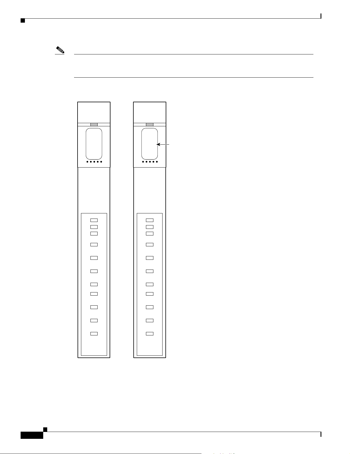
• AX-VISM-8T1—Support s u p to eig ht T 1 lines car rying d igitiz ed voice
• AX-VISM-8E1—Support s u p to eig ht E 1 lines car rying d igitiz ed voice
Release 3.0, Part Number OL-2521-01 Rev. D0, June 2004
Cisco VISM Installation and Configuration Guide
1-1
Page 24
VISM and VISM-PR Card Types
Note Using the Servi ce Resour ce Modul e ( SRM) a nd the 1 :N redun da ncy feat ures , ot h er phy sica l
configurations are supported. Refer to the “VISM and VISM-PR Ca rd Feat ures ” se ctio n on page 1-6
for more detail s.
Figure 1-1 VISM T1 and E1 Front Cards
Chapter 1 Overview of the VISM and VISM-PR Cards
CLEI code label
ACT
STBY
FAIL
PORT 1
PORT 2
PORT 3
PORT 4
PORT 5
PORT 6
PORT 7
PORT 8
VISM
8T1
T1 front card
ACT
STBY
FAIL
PORT 1
PORT 2
PORT 3
PORT 4
PORT 5
PORT 6
PORT 7
PORT 8
VISM
8E1
E1 front card
18738
1-2
Cisco VISM Installation and Configuration Guide
Release 3.0, Part Number OL-2521-01 Rev. D0, June 2004
Page 25
Chapter 1 Overview of the VISM and VISM-PR Cards
C
E
H
el
S
L
There are two types of VISM-PR front cards (see Figure 1-2):
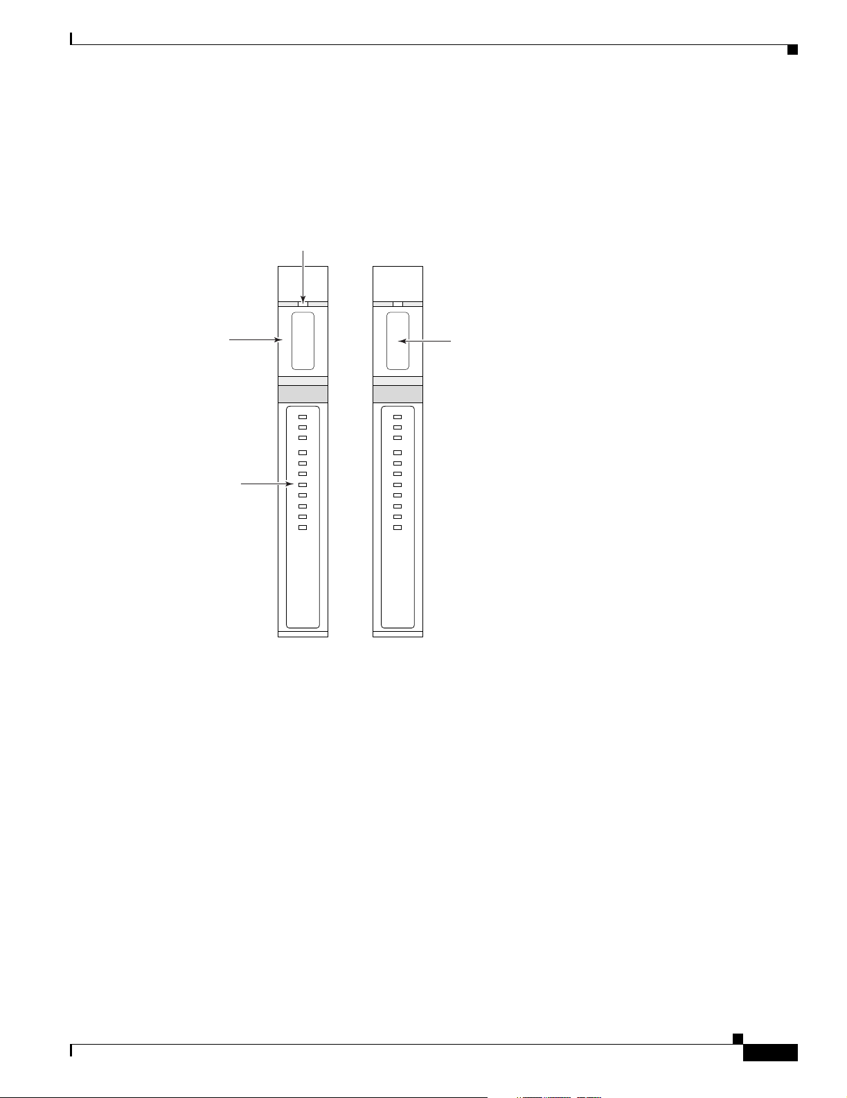
• MGX-VISM-PR-8T1— Supports up to eight T1 lines carrying di gitized voice
• MGX-VISM-PR-8E1— Supports up to eight E1 lines carrying di gitized voice
Figure 1-2 VISM-PR T1 and E1 Front Cards
Card Extractor
Release Slot
VISM and VISM-PR Card Types
ard
xtractor
CLEI
Code Lab
andle
tatus
EDs
ACT
STBY
FAIL
PORT 1
PORT 2
PORT 3
PORT 4
PORT 5
PORT 6
PORT 7
PORT 8
VISM
PR-8T1
ACT
STBY
FAIL
PORT 1
PORT 2
PORT 3
PORT 4
PORT 5
PORT 6
PORT 7
PORT 8
VISM
PR-8T1
72673
T1 E1
The VISM and VISM-PR front cards have the same associated back cards. There are two types of
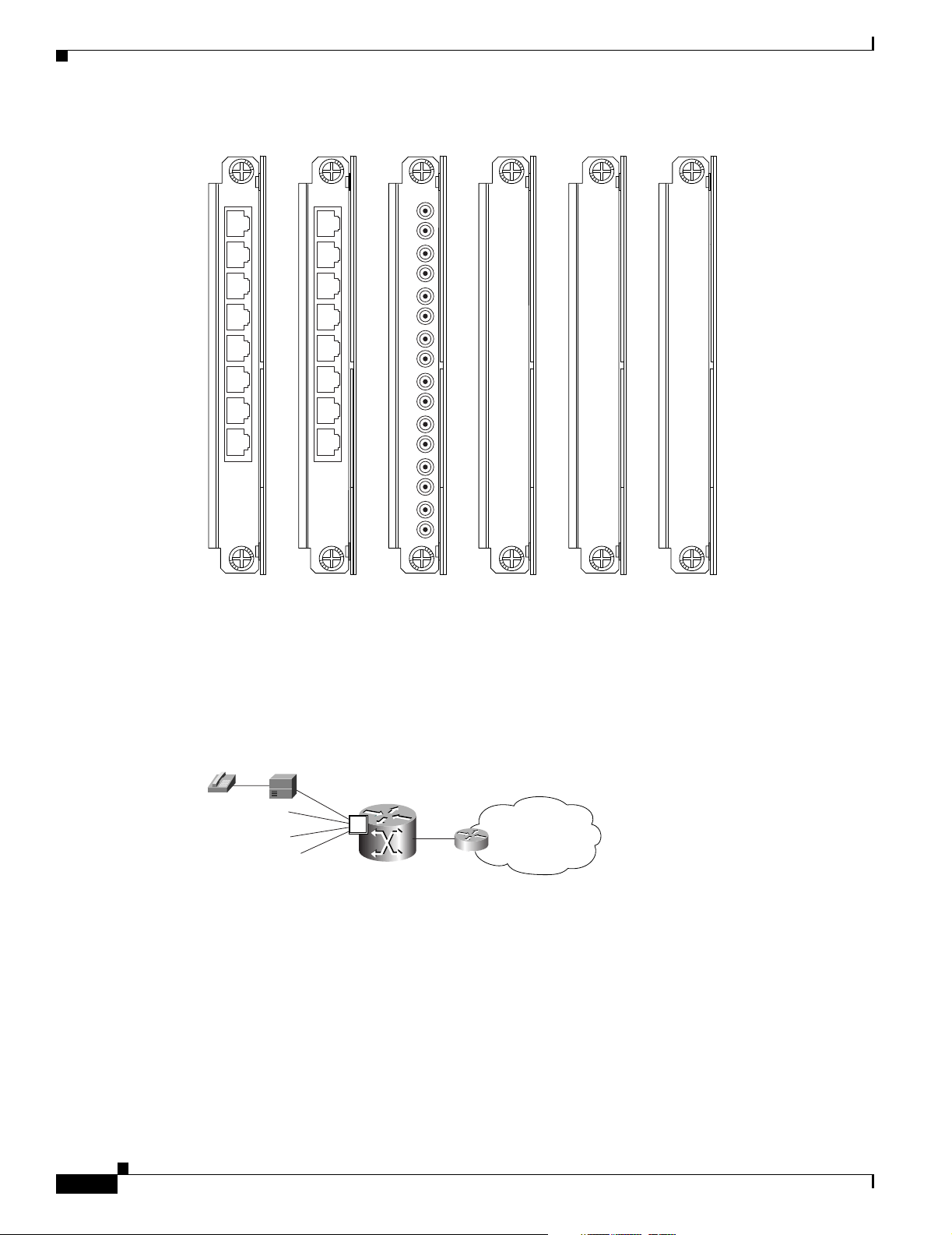
VISM/VISM-PR T1 back cards (see Figure 1-3):
• AX-RJ48-8T1—Support s e ight T1 li nes us in g R J-48 con ne ctors ; use wit h a T 1 f ron t car d.
• AX-R-RJ48-8T1—Suppor ts eig ht T 1 lin es; use wit h a re dundan t T1 f ro nt c ard.
There are four types of V ISM/VIS M-PR E1 back cards (see Figure 1-3):
• AX-RJ48-8E1—Suppor ts e ight E1 li nes us ing R J-48 c onn ector s; use with an E 1 front ca rd.
• AX-R-RJ48-8E1—Suppor ts eig ht E 1 lin es; use wit h a re dundan t E1 f ro nt c ard.
• AX-SMB-8E1—Suppor ts ei ght E1 line s us ing SM B conne ct ors; use wit h an E1 f ront car d.
• AX-R-SMB-8E1—Supp orts eig ht E 1 lines; use wit h a r e dundan t E1 f ro nt c ard.
Cisco VISM Installation and Configuration Guide
Release 3.0, Part Number OL-2521-01 Rev. D0, June 2004
1-3
Page 26
VISM and VISM-PR Card Types
3
Figure 1-3 VISM T1 and E1 Back Cards
Chapter 1 Overview of the VISM and VISM-PR Cards
RJ48-8T1
1
2
3
4
5
6
7
8
T1-RJ48 E1-RJ48 E1-SMB
RJ48-8E1
SMB-8E1
1
2
3
4
5
6
7
8
RX1
TX1
RX2
TX2
RX3
TX3
RX4
TX4
RX5
TX5
RX6
TX6
RX7
TX7
RX8
TX8
R-RJ48-8T1
R
E
D
U
N
D
A
N
T
Redundant
T1-RJ48
R-RJ48-8E1
R
E
D
U
N
D
A
N
T
Redundant
E1-RJ48
R-SMB-8E1
R
E
D
U
N
D
A
N
T
Redundant
E1-SMB
71218
The VISM or VISM-PR card and MGX 8000 Series switch combination provides an interface, or voice
gateway, between conventional TDM networks and packet -switc hed networks (se e Figure 1-4).
Figure 1-4 Cisco MGX 8850 and VISM as a Voice Gateway
PBX or
Central Office
T1/E1
Voice/TDM Networks
MGX 8850
with
VISM
V
Packet Network
(IP/ATM)
Packet Networks
1427
Connection to the packet network is pe rformed by Cisco MG X 8000 Series sw itch Processor Module
cards—PXM1, PXM1E, and PXM45—whi ch communica te with a VISM card through the switch’s
midplane cellbus. Refer to the documents listed in Table 5 of the “Related Documentation” section on
page xiv for more informat ion on the MGX 8000 Series sw itch midp lane cel lbus.
1-4
Cisco VISM Installation and Configuration Guide
Release 3.0, Part Number OL-2521-01 Rev. D0, June 2004
Page 27

Chapter 1 Overview of the VISM and VISM-PR Cards
VISM and VISM-PR Card Service Types
VISM cards are configured with the following service types:
• Constant bit rate (CBR)
Note CBR is not supported with a combination of a PXM1 with either an RPM or external
router.
• Variabl e bit ra te real tim e, VBR (RT)
• VBR non-real time (NRT)
VISM-PR card con nec tions w ith the R PM -PR ca rd re qu ire s th e V BR (NRT) 3 servic e t ype o n t h e
PXM1E and PXM45 platforms.
If you are using a VISM-PR card in com binatio n with a PXM1 E, PXM45, or RPM-PR card , you must
use the VBR (NRT) 3 selection when adding a connection.
The following connection ser vice t ypes can be c onfigured wit h VISM 3.0 and higher:
• VBR (RT) 2
VISM and VISM-PR Card Physical Characteristics
• VBR (RT) 3
• VBR (NRT) 2
VISM and VISM-PR Card Physical Characteristics
VISM cards are equipped with the following:
• Eight T1 or E1 po rt s
• Digital signal processors (DSPs)
• High-level data link control (HDLC) framer
• Broadband interface to the packet network
VISM Card Architecture
VISM card architecture provides the following:
• Flexibility that allows the incorporation of new or improved technology as it becomes available.
• Application flexibility that allows VISM to be used in a range of situations that provide
interoperability with a wide variety of equipment types.
• Modularity that allows equipment to be purchased and installed as it is needed for scalability.
Release 3.0, Part Number OL-2521-01 Rev. D0, June 2004
Cisco VISM Installation and Configuration Guide
1-5
Page 28
VISM and VISM-PR Card Features
C
rk
3
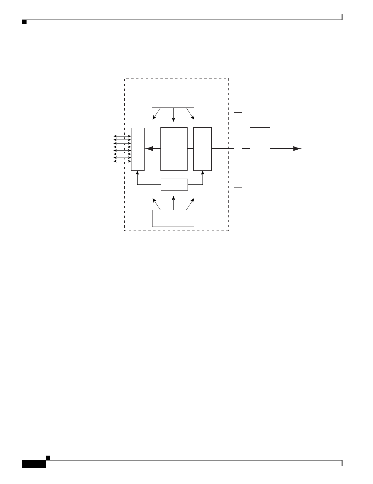
Figure 1-5 sh ows a simplified diagram of the VISM architecture and its major components.
Figure 1-5 VISM Card Block Diagram
Chapter 1 Overview of the VISM and VISM-PR Cards
VISM
Main CPU
(Control)
Cellbus
Framers
8 T1/E1 lines
from PBX or
entral Office
Digital
Signal
Processors
HDLC
Processor
Secondary CPU
(Datamover)
SAR
PXM
OC-3 to ATM
Packet Netwo
1429
The card is broadly divided into a TDM side and an ATM side. The T1/E1 framers, the array of DSPs,
and the HDLC processor support the TDM side. The ATM adaptation layer (AAL) and the segmentation
and reassembly (SAR) sec tions sup port the ATM side.
VISM is under the con trol of two i ndep en dent proc es sors. T he mai n pr oc ess or pe rfo rm s the c on trol
tasks—configuration, ca ll setup a nd tea rdown, and m anag emen t. The secon d pro cessor, the datamover,
handles the movin g and p roc essin g of t he voice and voic eb an d dat a t r affic through the syst em.
The VISM card i tsel f co ntain s no por ts fo r the con ne ction of ma nage ment sta tio ns. Workstations, PCs,
or terminals used t o ma nage VI SM mu st be att ached vi a t he PX M c ard whi ch pr ovides both se rial
EIA/TIA-232 and Ethe rnet por ts.
VISM and VISM-PR Card Features
VISM cards process high -densit y digit al voice c irc uits a nd provide d yna mic com pressi on, ec ho
cancellation, dejittering, silence suppression, and packetization. The VISM card uses the following
features which you c an c onfigu re:
• Eight standard T1 or E1 interfaces with the following line coding:
–
Bipolar 8-zero sub st itu tion ( B8Z S)—f or T1
–
Alternate mar k inversion (A MI)— f or T1
Cisco VISM Installation and Configuration Guide
1-6
–
High density bipolar 3 (HDB3)—for E1
Release 3.0, Part Number OL-2521-01 Rev. D0, June 2004
Page 29

Chapter 1 Overview of the VISM and VISM-PR Cards
• Voice over ATM (VoATM) using AAL2 cells—No Logical Link Control/Subnetwork Access
Protocol (LLC/SNAP) encapsulation.
Note Multiplexing is not suppo rte d f or A AL2 SVCs.
• VoIP using AA L5 c ells to R F C 1889 .
• Extended Superframe (ESF) fram ing with or without cyclic redunda ncy check (CRC).
• Pulse code modulation (PCM) A/Mu law codecs.
• Programmable 24, 3 2, 48, 6 4, 80 , 96, 1 12, 1 28 ms tai l d ela y n ear end EC AN.
• Voice compression with the follow ing standards:
–
G.711
–
G.726-16k
–
G.726-24k
–
G.726-32k
–
G.726-40k
VISM and VISM-PR Card Features
–
G.729a
–
G.729ab
–
G.723.1-H
–
G.723.1a-H
–
G.723.1-L
–
G.723.1a-L
Note The G.723.1 codecs are not supported in combination with the VISM card. The G.723.1
codecs are supported with the VISM-PR card.
• Nx64 clear channel (N = 1 only) suppor t.
• Voice activity detection (VAD) and comfort noise generation (CNG) using variable threshold energy
(Cisco proprietar y).
• Call agent Simple Gateway Control Protocol (SGC P) Version 1.0, 1.1, 1.5, SGCP 1.1+, 1.5, and
Media Gateway Control Protocol ( M GCP) 0 .1 and 1.0.
• Backhauling channel associated signaling (CAS) signaling to a call agent using xGCP (backhauling
can be accomplished with any supported SGCP and MGCP protoc ol).
• Backhauling Primar y Rat e Int erfac e (PRI ) sign al ing via R eli abl e Us er D at agra m Prot oco l (RUDP)
to a call agent.
• Common channel signaling (CCS) transport across an AAL5 trunk.
• Fax and modem VoIP bearer transmissi ons.
• Dual (redundant) virtual c ircuits a cross the pa cket network .
• Full continuity testing (CO T ). Supports origination and terminat ing loop back and tra nsponder CO T
between VISM and the central office on the TDM side.
• Loop timing, whi ch ca n be u sed a s th e ma ster cl ock fo r t he e nt ire MG X 80 00 Ser ies pla tfor m an d
local clock.
Release 3.0, Part Number OL-2521-01 Rev. D0, June 2004
Cisco VISM Installation and Configuration Guide
1-7
Page 30

VISM and VISM-PR Card Features
• Line loopback (DS1) toward t he T DM l ines .
• Channel loopback (D S0) t oward both t he T D M l ine s and t he ATM network.
• Transmission and reception of bit error ra te tester (BERT) signals over loopbacked lines.
• Redundant alarm indi cati on si gnal (R AI) and a larm i n dica tion signa l ( AIS ) alarm s.
• Extracting a DS0 CCS channel and directing it to the TDM signaling function.
• 1:N cold redundancy using subrate multiplexing (SRM)-3T3 (bulk mode support for T1 lines only)
and SRM-E (for OC3) capabilities. Calls do not persist during switchover.
• Graceful shutdown of ongoing voice calls when the V ISM is taken out of service for ma intenan ce
or other reasons. Forced shutdown is also suppo rted.
Caution A forced shutdown of the VISM or V ISM-PR car d m ay r esul t i n dro ppe d ca ll s.
Redundancy and Bulk Distribution
Redundancy for VISM c ards with or wi thout bulk d istr ibution ca n b e pr ovided t hrou gh the Servi ce
Redundancy Module (SRM) and SRM -E. Redund ancy for VISM i s also provided by Media Gat eway
Controller (MGC) redundancy groups. VISM redundancy is cold redundancy in which ongoing calls do
not persist during switchover.
Chapter 1 Overview of the VISM and VISM-PR Cards
Note SRM-E is supported with PXM1 and PXM1 E card s only.
Redundancy with bulk dist ribution re quires a spare VISM card to be installed . The system uses the three
T3 ports of the SRM back card instead of the normal T1 lines on the VISM back cards. VISM cards in
bulk distribution mode do not require back cards.
The TDM voice data tr ansmitted or rec eiv ed o ver th e T3 ports are di strib uted to the VISM ca rd as if they
had been received over VISM T1 back card ports in the normal manner. This feature reduces the number
of physical lines required to support VISM, but requires external equipment to multiplex and
demultiplex the T1 data onto the T3 lines.
With or with out bu lk distrib ution, r edundancy al lo ws for the spar e VISM card to automatical ly take o ver
the functions of a failed VISM card . When the failed card is repa ired, switching back to the repa ired card
is not automatic. You must manually change the repai red car d back to the acti v e state with t he com mand
line interface. See Ch apte r 4, “Configuring VISM Feature s. ”
Note 1:1 redundancy using Y-cables is not supported by VISM.
Redundancy can also b e configured a t t he ATM permanent virtual c irc uit s ( PVC s) l evel. Two separate
PVCs can be set up, each using a di fferent PXM physic al port and e ach rout ed to a separ ate route r.
Configure one PVC as active and the o ther as standby. Both PVCs are monitored by heartbeat OAM F5
loopback cells every 200 ms. If three consecutive OAM cells are lost, the PVC fails, and only the
remaining PVC is active. A PVC will recover automatically when five consecutive OAM cells are
received while the PVC remains in standby mode (no automatic fallback to active state is provided).
Control and bearer PVCs can be set up with a redundant PVC.
1-8
Cisco VISM Installation and Configuration Guide
Release 3.0, Part Number OL-2521-01 Rev. D0, June 2004
Page 31

Chapter 1 Overview of the VISM and VISM-PR Cards
Operating Modes
The VISM/VISM- PR ca rd perf orm s in th e f oll owing opera ti ng modes :
• Voice over IP (VoIP) switching/trunking
• Switched AAL1 switched virtual circuits (SVC s)
• Switched AAL2 SVC
• Switched AAL2 PVC—this mode is not supp orted in VISM Rele ase 3.0
• AAL2 trunking
• VoIP and switched ATM AAL1 SVC
The VISM/VISM-PR card, in order to support the operating modes, supports connections to three major
interfaces:
• Voice TDM network
• ATM networ k
• Call agent—signaling (either CAS or CCS but not both) and call control
In VoIP switching, swit ched AAL2 PVC, A AL1 SVC, and AAL 2 SVC modes, all th ree of these
interfaces are al ways present an d acti ve . In AA L2 trunking mode, the interfa ce to the call age nt interf ace
is not present and the only active interfaces are to the TDM network and the ATM network.
The operating modes, combined wi th features you configure, are used by VISM cards in a wide variety
of telephony applica tions. For exa mple :
VISM and VISM-PR Card Features
• Provide many of the functions of a tandem (Class 4) sw itch. VISM can be used to replac e, or
partially offload, a Tandem switch by directing calls over a packet network rather than the
conventional voice TDM network.
• Concentrate voice and data user services onto a single broadband circuit for transmission over the
packet network. In this applic ation , VISM perfor ms as a front en d to a voice gateway.
• The VISM/MGX combination is used to concentrate voice (and fax/modem voiceband data) user
services over a preprovisioned AAL2 trunk. VISM passes bearer and signaling data across a packet
network and does not pe rform c all se tup and t eardown fun ctions.
VoIP Switching and Switched AAL2 PVC Operating Modes
In VoIP switching mod e and switch ed AAL2 PVC mo de, VISM oper ates under the control of a call ag ent
to set up and tear down calls. When a call is set up, VISM transports voice payloads over an ATM
network to the called station destination. VISM performs either as a vo ice gateway or as a multiservice
access front end to a voice gateway.
Note This document refers to the device that provides the interface between VISM and the telephone
Signaling System 7 (SS7) as a call agent. Other ter ms that descr ibe the same device are Virtual
Switch Controller, Media Gateway Controller, and Gatekeeper.
Release 3.0, Part Number OL-2521-01 Rev. D0, June 2004
Cisco VISM Installation and Configuration Guide
1-9
Page 32

Chapter 1 Overview of the VISM and VISM-PR Cards
rk
5
T
VISM and VISM-PR Card Features
Figure 1-6 shows the major functional blocks and interfaces for the V oIP switching and switched AAL2
PVC operating modes.
Figure 1-6 VISM Block Diagram for VoIP Switching and Switched AAL2 PVC Operating Modes
VISM
CCS (Q.931)
Agent
CCS
CCS
CAS/CCS
Processing
CAS (xGCP)
xGCP
Connection
Handling
Call
1/E1 Lines
CAS
Voice
TDM Line
Handling
The CAS signaling path on the TDM side is embedded in the voice stream but is separated at the bearer
processing function. The CAS signaling then joins the CCS signaling path for CAS/CCS processing and
is backhauled to the call agen t. The path bet ween th e call ag en t and bearer processing, via a conn e ctio n
handling function, is for call setup and teardown.
Voice TDM Network Interface
The voice payload path is shown as a solid line along the bottom of Figure 1-6. All external TDM
streams arrive and depar t on the T1/E 1 lin es. De pendi ng on t he ap plic at ion, the se st rea ms consi st of
voice bearer channels (with or without CAS signaling) and separate CCS channels (if CCS signaling is
used). The TDM line handl ing functi on provides the physi cal laye r interfac e, which inc ludes fra ming,
line codes, clocking, loopback s, physical alarm s, etc. Be arer cha nnels, including CAS, are sent to the
bearer processing function . CCS chann els are sent to the CAS/CCS processi ng funct ion.
Further processing of the bearer chann els is per formed by the DSPs. Thi s processi ng provides ECAN ,
compression, A/Mu law conversion, silence suppression, an d fax/mo dem ha ndli ng. If CA S signa ling is
present, signaling bits are extracted at the DSP stage and sent to the CAS/CCS processing function.
CAS
Voice
CAS
Bearer
Processing
Connection Setup
Teardown
ATM Processing
Voice payload
3231
To AT M
Netwo
ATM Network Interface
The A TM processing function receives the processed DS0 voice streams and prepares them for transport
over a pa cke t ne tw ork . The v o ice st reams are divided into specifi c sam ple pe rio ds (for ex ampl e, 5 ms or
10 ms) and formatted into service specific convergence sublayer (SSCS) packets appropriate for the
method of transport over the ATM network. The available transport methods are V oIP (using AAL5) and
voice over AAL2. Processing of the ATM packets further segments the voice payload into ATM cells for
transport over the network using a SONET port on the PXM car d.
Cisco VISM Installation and Configuration Guide
1-10
Release 3.0, Part Number OL-2521-01 Rev. D0, June 2004
Page 33

Chapter 1 Overview of the VISM and VISM-PR Cards
5
T
Call Agent Interface
The call agent interface consists of CAS signaling or CCS signaling and call control. The path between
the call agent and bea re r proc ess ing, v i a a co nne cti on handl ing funct ion, is for ca ll se tup and teardown.
The CAS signaling path on the TDM side is embedded in the voice stream (bearer DS0s) and is separated
at the bearer processing func tion. Th e CAS signaling (robbed b its, digit s, and tones) is passed to the
CAS/CCS processing function where it is passed (backhauled) to the call agent under the control of the
call agent. The mechanism for communicating between VISM and the call agent is a gateway control
protocol:
• MGCP
• SGCP
• SRCP
The separate CCS si g naling path c han nels are p assed t o th e CAS/CCS p roce ssing fu nction a nd
backhauled to the call ag ent . T he C CS sign ali ng is t ran spor ted a s I SDN Q.93 1 m essag es both on the
TDM side and on the call agent side. On the TDM side, the messages are carried in the Q.921 layer
protocol (which termin ates at the VI SM card). On the call agen t side, com municatio n with the ca ll agent
consists of Q.931 messages encapsulated in RUDP/UDP/IP packets. The Q.931 connection is terminated
at the call agent and not at the VISM card.
VISM and VISM-PR Card Features
The call control path uses MGCP, SGCP, and SRCP for call setup and teardown. Bec ause signaling and
call control are so intertwined, both call control and CAS use the sa me path and protocol for the VISM
card to call agent communications.
AAL2 Trunking Operating Mode
In the AAL2 tru nkin g o pe ratin g m ode, t he V ISM ca rd serves as an ac cess t o on e or m ore t runk s t o
preprovisioned locations. VISM may be used at both ends of the trunk, or at one end with a compatible
device at the other. In AAL2 trunking mode, VISM plays no part in call setup and teardown. Other
network elements hand le call cont rol whil e VISM merely handl es voice transpor t over the trunks.
Figure 1-7 sh ows the ma jor fun ction al bloc ks f or t he A AL 2 tr unkin g o pera ting m od e.
Figure 1-7 VISM Block Diagram for the AAL2 Trunking Operating Mode
VISM
CCS
Processing
CCS
1/E1 Lines
CAS
Voice
TDM Line
Handling
Bearer
Processing
ATM
Processing
CCS
CAS
Voice
To AT M
Trunk
3232
The AAL2 trunking mode is less com plex than the VoIP switching and AAL2 PVC switche d modes
because there is no call control involved—and no need for a call agent.
Release 3.0, Part Number OL-2521-01 Rev. D0, June 2004
Cisco VISM Installation and Configuration Guide
1-11
Page 34

VISM and VISM-PR Card Features
The voice bearer path is treated in the same manner as in the VoIP switching and AAL2 PVC modes,
except that only preprovisioned A AL2 PVCs are available for tra nsport of voice over the trunks. The
CAS signaling data is tra nsport ed over the ATM network in the same AAL2 trunk as Type 3 messages.
The CCS signaling data is transpo rted over the ATM network in a separate AAL5 PVC.
VoIP Trunking Operating Mode
The Voice over IP (VoIP) trunking feature all ows the VISM to conn ect to th e PBX, or cent ral office
digital systems, using T1/ E1 digital interfac es and converts the TDM bi t stream into RTP packets, after
ECAN and comp ression , an d tran spor ts i t over t he I P ne twor k.
No call agent is required for setting up and tearing down calls. You must configure the DS0 circuits. The
connection between VISM an d t he first router will be ATM after which it wi ll b e IP onl y. VISM and the
router can have one or multiple PVCs to transport the data. You have the option to configure PVC for
bearer or con t rol . I f t h e PVC i s co nfigure d a s be a rer an d n o con t rol P VC exi sts , th en PR I si gn al tr affic
and bearer traffic will go through this PVC. If you configure separate PVCs for control and bearer, PRI
signaling will go through control traffic only. You can modify some of the connection parameters after
it is added.
CAS is transported t o t he far end usi ng a C isco propr ieta ry fo rmat ( not NSE s). PR I is tra nsport ed over
RUDP to the far end once the trunk is provisioned between the originating and terminating VISM.
Chapter 1 Overview of the VISM and VISM-PR Cards
PRI transport is handled in a way identical to PRI backhaul except that the PRI traffic is sent to remote
gateway instead of a cal l a gen t. You can configure one line for PRI tru nki ng a nd anot her li ne fo r PRI
backhauling.
You must provisi o n t h e LAPD trunk when using this feature. You must confi g u re a line number, remote
gateway IP address, loca l UD P p ort, a nd remo te gateway UD P po rt , an d th en op en a tr unk . You must
then configure the D- ch anne l a s a tr unk or b ackha ul:
• To configure the D channel as trunk, use the addlapdtrunk command prior to the addlapd
command. If the addlapd command has been previously executed for that line, the command is
rejected.
Note Two D channels on one l ine a re no t suppor t ed.
• To configure the D channel as backhaul, use the addses command prior to the addlapd command.
If you do not configure either trun k or session, t he addlapd command is rejected.
AAL1/AAL2 SVC Operating Mode
Release 3.0(0) supports t he AAL1 and AAL 2 switche d virtual circ uit (SVC ) operatin g modes for
VISM-PR cards. VoAAL1 SVC is supported with the G.711 codec and clear channel.
Note VAD is not support ed in c om bina tion w ith A AL1 SV Cs. CA S is no t supp orte d in c ombi nat ion wi th
SVCs.
1-12
Cisco VISM Installation and Configuration Guide
Release 3.0, Part Number OL-2521-01 Rev. D0, June 2004
Page 35

Chapter 1 Overview of the VISM and VISM-PR Cards
VoAAL2 SVC is su pport ed wit h the G.71 1, G.726 , G.7 29a, a nd G.729 ab cod ecs a nd p rofiles 1, 2, 3, 7 ,
8, 100, 101, 110, and 200.
Note The AAL1/AAL2 SVC operating modes require you to use a PXM1E or PXM45 in your MGX 8000
Series switc h ch ass is.
Installing VISM Hardware and Software
You can install VISM cards in the following configurations:
• Install a VISM front card and a back card as a pair. The front and back cards must occupy the same
slot.
• Install a VISM front card wi th no ba ck card. Th e MGX 800 0 Series b u lk dis tri b ution fe ature allows
this configurati on. Access to a nd from the T DM lines is perf ormed b y the Se rvice Reso urce Module
(SRM) and the MGX 8000 Series distribution bus.
Installing VISM Hardware and Software
Note VISM cards in bulk distribution mode do not require back cards.
• Install a VISM fro nt c ard a s a red und an t ca r d wi th a redun da nt b ack ca rd in th e sa me sl o t.
Note VISM T1 front cards require T1 back cards and E1 front cards require E1 back cards. Ensure that
your configuration meets this require ment.
In each of these configurati ons, co nnecti ons to the p acket network ar e made through th e MGX 800 0
Series cellbus and an OC-3 port located on the MGX 8000 Series PXM card. Refer to the “VISM and
VISM-PR Card Physical Characteristi cs” section on pa ge 1-5 for more information on front an d back
cards.
Installing VISM Cards in MGX 8000 Series Chassis
VISM front and back cards can be installed in the fo llowing MGX 800 0 Series platforms with th ese basic
guidelines:
• Cisco MGX 8850 Release 1—Up to 24 slots ca n be used for VISM card s.
• Cisco MGX 8250—Up to 24 slots can be used for VISM card s.
• Cisco MGX 8230—Up to eight slots ca n be used for VISM c ards.
The VISM card can be u sed wi th t he Proc essor M odu le-1 (P XM1) ca rd.
Installing VISM-PR Cards in MGX 8000 Series Chassis
VISM-PR front and back cards can be insta lled in th e following MGX 8000 Series platf orm s with the se
basic guidelines:
• MGX 8250 and MGX 88 50—U p t o 24 s lo ts c an be use d for V ISM-PR car ds.
• MGX 8230—Up to 8 slot s ca n be used for VI SM- PR ca rds.
Cisco VISM Installation and Configuration Guide
Release 3.0, Part Number OL-2521-01 Rev. D0, June 2004
1-13
Page 36

Installing VISM Hardware and Software
U
S
L
S
The VISM-PR card can be used with the following Processor Module cards:
• PXM1
• PXM1E
• PXM45
You must install an additional fan tray spacer at the bottom of your MGX 8000 Series switch chassis
directly above the intake plenum if you are using the VISM-PR card in combination with the PXM45
card. Refer to the Cisco MGX 8850 Hardware Installation Guide, Release 3 for step-by-step instructions
to install a fan tray.
MGX 8850 and MGX 8250 Chassis
VISM and VISM-PR card installation in a Cisco MGX 8850 or MGX 8250 platform consists of installing
one front card and one back car d (if not using th e bulk distribution fe a ture ) in eit her th e upper or lower
shelf of the cha ssis. You can use slots 1 to 6, 9 t o 14, 1 7 to 22 , an d 25 to 30 to inst all VISM c ards (se e
Figure 1-8).
Figure 1-8 Available Chassis Slots for VISM Cards in the MGX 8850 and MGX 8250—Front View
Chapter 1 Overview of the VISM and VISM-PR Cards
Upper Shelf Slots
12345678910111213141516
pper
helf
VISM VISMVISMVISMVISMVISM
VISM VISM VISM VISM
VISM VISM
ower
helf
VISM
VISMVISM
VISMVISM VISMVISM
VISM VISMVISM VISMVISM
17 18 19 20 21 22 23 24 25 26 27 28 29 30 31 32
Lower Shelf Slots
VISM VISM
31428
Note If you use all t he available s lots , you c an configu re t he M GX 88 50 an d MG X 8 250 wi th u p to 24
VISM cards. However, the two lower shelf cellbuses can each sustain a bandwidth of one
OC-3/STM-1 link. This bandwidth limits the number of E1 ports on the lower shelf, when using the
G.711 codec, to 78, w hic h lim i ts t he n umb er of VI SM card s t o 10 .
Cisco VISM Installation and Configuration Guide
1-14
Release 3.0, Part Number OL-2521-01 Rev. D0, June 2004
Page 37

Chapter 1 Overview of the VISM and VISM-PR Cards
1
2
3
4
5
6
7
MGX 8230 Chassis
VISM card installation in a Cisco MGX 8230 platform consists of installing one front card and one back
card (if not using the bulk distribution feature) in either a left or right shelf slot. You can use slots 3 to
6, and 10 to 13 to install VISM cards (see Figure 1-9). If you use all the available slots, you can configure
the MGX 8230 with up to eight VISM cards.
Figure 1-9 Available Chassis Slots for VISM Cards in the Cisco MGX 8230—Front View
Installing VISM Hardware and Software
Reserved for SRM cards
VISMVISMVISMVISM
Reserved for PXM cards
VISMVISMVISMVISM
Installing VISM and VISM-PR Front and Back Cards
This section describes the following hardware installation procedures:
1. Installing a VISM or VI SM- PR Fr ont Card
2. Installing a VISM Back Card
3. Connecting Cables to Cards
Installing a VISM or VISM-PR Front Card
Complete the following instructions to install a VISM or VISM-PR front card:
14
13
12
11
10
9
8
57104
Step 1 Position the rear ca rd gu i des over the appr opr iate slot in the cha ssis.
Step 2 Gently slide the card all the way into the slot and press the insertion/extractor lever until it snaps into
the vertical (MGX 8250 or MGX 8850 ) or horizo ntal (MGX 823 0) position .
Caution The card should slide in and out wit h only sl ight fr ict ion o n the E MI ga skets on the adja cen t boa rd.
Do not use fo rc e. Investigate any bi nd ing.
Release 3.0, Part Number OL-2521-01 Rev. D0, June 2004
Cisco VISM Installation and Configuration Guide
1-15
Page 38

Installing VISM Hardware and Software
Installing a VISM Back Card
Complete the following instructions to install a VISM back card:
Step 1 Ensure that the two extractor levers are at the “in” position.
When you insert the card into the slot, the levers should be vertical or horizontal along the line of the
back card.
Step 2 Position the rear card gui des over the appropr iate slot in the chassis.
Step 3 Gently slide the card all the way into the slot.
Step 4 Tighten the two captive screws on the back card’s faceplate.
Step 5 Tighten the upper and lower screws to prevent misalignment of the card.
Note Do not overtighten the screws. Tighten them only enough to secure the card.
Chapter 1 Overview of the VISM and VISM-PR Cards
Connecting Cables to Cards
After you install the VISM fron t and back cards, connec t the T1 or E1 ca bles to the RJ-48 or SMB
connectors on th e back cards. The T1 and E1 cab les connec t the eight por ts on the back c ards to the v oice
T1 or E1 lines. The T1 lines use RJ-48 connec tors. The E1 line s use eithe r RJ-48 or SMB connect ors.
Note In all text references to cables, “transmit” refers to a cable used for data moving away from the VISM
card, and “receive” refers to a cable used for data moving toward the VISM card.
Cabling for RJ-48 Connectors on T1 and E1 Ports
For T1 and E1 po rts that co nne ct thro ugh a n RJ-48 c on ne ctor, each c onnec to r ha s:
• Transmit TIP (TTIP) pin
• Transmit RING (TRNG) pin
• Receive TIP (RTIP) pin
• Receive RING (RRNG) pin
• Two pins for shielded g ro und
1-16
Cisco VISM Installation and Configuration Guide
Release 3.0, Part Number OL-2521-01 Rev. D0, June 2004
Page 39

Chapter 1 Overview of the VISM and VISM-PR Cards
ld
The connector wir ing is shown in Figure 1-10.
Figure 1-10 RJ-48 PIN Connector
Installing VISM Hardware and Software
IN
IN
IN
IN
TTIP
TRNG
TEST-RNGP
TEST-TIP
Cabling for SMB Connectors on E1 Ports
When you use the E1 VISM back card with SMB cables, the E1 trunk cables connect the customer
DSX-1 cross-conne ct point or E1 c hann el s er vice u nit ( CSU ) to the n ode u s ing 75 -ohm c oa xia l cab l e
fitted with SMB connectors.
RJ-48 Pins
2
1
5
4
3
6
7
8
RTIP
RRNG
OUT
OUT
11763
ground/shie
Removing VISM and VISM-PR Front and Back Cards
This section describes the following hardware installation procedures:
• Removing a VISM or VISM-PR Front Card
• Removing a VISM Back Card
Removing a VISM or VISM-PR Front Card
Step 1 Insert a small, flat-blade scre wdriv er into th e slot in the insertion/e xtractor le v er and press until the latc h
springs open, to approxima tely 10°.
Step 2 Continue to lift the insertion/extractor lever to disconnect the connector.
Step 3 Gently pull the card out of the chassis.
Removing a VISM Back Card
Step 1 Remove any cables connected to the back card.
Step 2 Use a small, flat-blade screwdriver to unscrew the two retaining screws in the back card’s faceplate.
Release 3.0, Part Number OL-2521-01 Rev. D0, June 2004
Cisco VISM Installation and Configuration Guide
1-17
Page 40

Installing VISM Hardware and Software
Step 3 Pull both of the extractor levers out to the horizontal position.
This action starts the removal of the card.
Step 4 Gently pull the card out of the chassis.
Applying Power to the VISM Card
You apply power to a VISM card b y installing it i n a n alread y runn ing MGX 80 00 Seri es platfo rm, or b y
applying power to a chassis that has a previously installed VISM card. When power is applied, the VISM
card performs extensive testing and initialization functions. If the ca rd ha s alr eady be en co nfigured, the
initialization downloads the configuration data from the disk on the PXM. This process takes
approximately two minu tes, du ring wh ic h th e LED ind ica tor bl inks. W hen th e Active LED b ec omes
solid green, the card is in the Acti ve state and is ready to be conf igured (if necessa ry) and able to pro cess
data.
Installing VISM Software Upgrades
Chapter 1 Overview of the VISM and VISM-PR Cards
VISM Release 3.0 provides a gracef ul upgrade procedu re from Rele ase 1.5 and highe r. The existing
VISM configuration is pr eserved thro ugh out t he upg ra de p roce dur e, pr ovided t hat the fol lowing
conditions are met :
• The Cisco MGX 8000 Series plat form must be configure d with at least two VISM cards in a
redundant configurat ion. Refer to t he add redundancy, addred, command in the Cisco MGX 885 0,
MGX 8250, and MGX 8230 command re ferenc e guides fo r detail s.
• The VISM cards must be running VI SM 2.0 and be co nfigured to the de sired co nfiguration.
• The VISM Release 3. 0 softw are mus t ha ve be en alread y do wnload ed to the Cisco MG X shelf. Re fer
to Release Notes for Cisc o Voice Interworking Services Module Release 3.0(0) for details.
• Cisco recommends an upgra de in the back up boot to version 3. 0.
Complete the following steps to upgrade the VISM software. In the following procedure, old-rev refers
to the firmware before the upgrade (2.0) and new-rev refers to the firmware after the upgrade (3.0).
Note If the VISM ca rd y ou ar e upg radi ng is par t of a n onr ed undan t configur ati on , co mpl et e Step 1 to
Step 4 only.
Step 1 Log in to the active PXM card (slot 7 or 8).
Step 2 Save the existing configuration as a cont ing en cy plan by ent eri ng :
savesmcnf <SM slot#>
1-18
where:
SM slot# is the slot number of the active VISM card.
This command saves the existing configuration to the C:\CNF directory. This file can be used during the
downgrade procedure, if necessary.
Cisco VISM Installation and Configuration Guide
Release 3.0, Part Number OL-2521-01 Rev. D0, June 2004
Page 41

Chapter 1 Overview of the VISM and VISM-PR Cards
Step 3 Execute the PXM install command for the backup boot image:
install bt sm <SM slot#> <new bb rev>
where:
SM slot# is the slot number of the act ive card, and new bb rev is the version number of t he new backup
boot image.
This command downloads the backup boot image to the flash in the VISM card slot you specified. The
new backup boot image takes effect upon the next car d reset.
Step 4 Execute the PXM install command:
install sm <SM slot#> <new-rev>
where:
SM slot# is the slot number of the VISM card that was active before the upgrade process started, and
new-rev is the file name of the new firmware (for example, vism_8t1e1_002 .001. 000.000 .fw).
This command causes the standby VISM card to reset and be placed in the hold state, running the
new-rev firmware. The active VISM card is unaffected by this comman d. At thi s point the primary
firmware is still the old- rev and the s econd ar y firmware is new-rev.
Step 5 Execute the PXM newrev command:
newrev sm <SM slot#> <new-rev>
Installing VISM Hardware and Software
where:
SM slot# is the slot number of the VISM card that was active before the upgrade process started, and
new-rev is the filename of the new firmware.
This command causes th e standby VISM ca rd to becom e the active VISM card runnin g the new-rev
firmware. The previously active VISM card is placed in the hold state, becoming the new standby VISM
card, and is still running the old-rev firmware. The primary and secondary fir mware switches with the
new-rev becoming the primary firmware.
Step 6 Execute the PXM commit command:
commit sm <SMslot#> <new-rev>
where:
SM slot# is the s lot nu mber of the n ew standby VI SM c ard a nd new-rev is th e filename o f t he new
firmware.
This command cau ses bot h VISM card s to run t he ne w- re v f irmwar e. After a short tim e, the c ards swi tch
automatically so that the originally acti ve VISM c ard becomes the act iv e card and the originally stan dby
VISM card becomes the standby card. The two VISM cards are now back to their original condition
except that both cards are now runnin g the new-rev firmware.
Step 7 Log in to the active VISM card and use the display commands (dspendpts, dspcasvar, etc.) to confirm
that the configuration h as bee n p reser ved thr oug h the upg rade proc ess.
Cisco recommends that you further verify the configuration by making some minor modifications to the
configuration, checking that the changes have been executed correctly, and then changing the
configuration back again.
See Appendix B, “VISM and VISM-PR—3.0 Specifications” for more information about the VISM and
VISM-PR card specifications.
Release 3.0, Part Number OL-2521-01 Rev. D0, June 2004
Cisco VISM Installation and Configuration Guide
1-19
Page 42

Software Upgrades
Software Upgrades
VISM/VISM- PR R el e as e 3.0 p r ovides a gr ac ef ul u pgr ad e pr oc ed ure f or t he fo ll owing rele a ses :.
• From VISM 1.5 to V ISM 3 .0
• From VISM 2.1 to V ISM 3 .0
• From VISM 2.2 to V ISM 3 .0
Caution Installing VISM software upgrades f rom V ISM Re lease 2. 2 wi th CALE A t o V ISM Re lease 3 .0
without CALEA is not graceful.
Prerequisites
To ensure that th e V ISM/VI SM- PR c on figuration is pr eser ved thr ough out the up grad e p roce dur e, y ou
must complete the prerequisites listed in this section.
Before starting the grac eful upgr ade proc edure, c omplete the following prere quisite s:
• Configure your MGX 8000 Series shelf with at least two VISM cards in a redundant configuration.
Chapter 1 Overview of the VISM and VISM-PR Cards
For more information on adding redundancy, refer to the add redundancy, addred, command in the
Cisco MGX 8250, C isco MGX 823 0, and Cisco M GX 88 50 PX M1 -base d C omm and Refe re nce
documentation and the Cisc o MG X 8 830 and M GX 885 0 PXM 1E/ PXM 45-ba sed Comm an d
Reference document ation.
• Ensure that the VISM/VISM-PR cards are running at least Release 2.1.
• Download software Rele ase 3 .0 fo r VI SM /VI SM- PR to the M GX 80 00 S eri es shel f.
• If you are using the CAL EA feature, ensure that you have the version of VISM/VISM-PR sof tware
that supports CALEA.
VISM/VISM-PR Upgrades with PXM1
This section describes the pr ocedu res for upgra ding VISM/ VISM-PR sof tware when the
VISM/VISM-PR is used with a PXM1 card.
Download VISM/VISM-PR Boot Code and Firmware to PXM1
To download the VISM/VISM-PR boot code and firmware to the PXM1 card, use TFTP.
Step 1 Log in to you r TFT P se rver.
Step 2 Download the bootcode a nd firmware images fr om the Cisc o website.
Step 3 Download the selected revision of serv ice module boot code into t he service module.
1-20
a. tftp <node_na me or IP a ddress>
b. bin
c. put <backup boot> POPEYE@SM_1_0.BT
d. quit
Cisco VISM Installation and Configuration Guide
Release 3.0, Part Number OL-2521-01 Rev. D0, June 2004
Page 43

Chapter 1 Overview of the VISM and VISM-PR Cards
Step 4 Download the selected firmware file.
T o upgr ade all VISM car ds, procee d to Step 4c. T o upg rade an indi vi dual VISM car d, procee d to Step 4d.
a. tftp <node_na me or IP address>
b. bin
c. put <FW file> POPEYE@SM_1_0.FW
quit
d. put <FW file> POPEYE@SM_1_<slot number of card to upgrad e>.FW
quit
Note Do not enter two put commands in the same TFTP session.
Step 5 Proceed to the “Upgrade VISM/VISM- PR Fir mware wit h PXM 1 Card” s ectio n on pa ge 1-21 to install
the download.
Software Upgrades
Upgrade VISM/VISM-PR Firmware with PXM1 Card
Software Release 3.0 is for VISM and VISM-PR cards. Ensure that the VISM and VISM-PR cards have
the minimum boot c od e versi on of vism _8t 1e1 _VI8_ BT_ 3. 1.00.f w.
The following versions of VISM software Release 3.0 are available:
• 003.000.000.000—w ithout CA LEA
• 003.050.000.000—w ith CAL EA
In this procedure the following condi tions ap ply:
• If two VISM or VISM-PR cards are part of a redu ndancy group, initially the pr imary ca rd is in the
active state, and the se conda ry car d is in th e stan dby state.
• Old-rev refers to the firmware, Relea se 2.2 an d prior.
• New-rev refers to the firmware after the upgrade, Release 3.0.
Perform the firmware upg rade on the VISM or V ISM-PR c ards. Do not re move the VISM car ds an d
replace them with VISM-PR cards at this time.
Step 1 Log in to the active PXM1 card (slot 7 or 8).
Step 2 Save the existing configurat ion as a cont ing en cy plan by e nt eri ng:
savesmcnf <SM slot#>
This command saves the e xistin g configuration in the C:CNF directory. This f ile can be used durin g the
downgrade procedure, if necessary.
Step 3 Execute the PXM install command:
install sm <SM slot#> <new-rev>
where:
SM slot# is the slot number of the prim ary V ISM o r V ISM- P R ca rd an d new-rev is the file name of the
new firmware (for example, vism_8t1e1_003 .000.000 .000. fw).
Release 3.0, Part Number OL-2521-01 Rev. D0, June 2004
Cisco VISM Installation and Configuration Guide
1-21
Page 44

Software Upgrades
Step 4 Execute the PXM newrev command:
Step 5 Execute the PXM commit command:
Chapter 1 Overview of the VISM and VISM-PR Cards
This command causes the secondary VISM or VISM-PR card to reset and come up in the standby state,
running the new-rev firmware. The primary VISM or VISM-PR card is unaffected by this command.
newrev sm <SM slot#> <new-rev>
where:
SM slot# is the slot number of the primary V ISM or VISM-P R card and new-rev is the filename of the
new firmware.
This command ca uses th e pr im ary VISM or VISM -P R ca rd to r eset a nd the s econd ar y VI SM or
VISM-PR card to beco me ac tive and runn in g th e new-rev firmware.
commit sm <SM slot#> <new-rev>
where:
SM slot# is the slot number of the primary V ISM or VISM-P R card and new-rev is the filename of the
new firmware.
The two VISM or VISM-PR cards ar e now back to their original c ondition except tha t both cards ar e
now running the new-rev firmware.
Step 6 Log in to t he active VISM o r VISM- PR ca rd and use the di spla y com ma nd s ( for exam pl e, dspendpts,
dspcasvar, and so forth) to confirm that the configuration has been preserved through the upgrade
process.
Note For more than one p rima ry V ISM or VISM -PR card in a redu nda ncy gro up, ensur e tha t the sec ond ar y
card is in the standby state and repeat Step 4 and Step 5 for each VISM card in the redun dancy group.
It is also recommended that you per form the following verifications:
• Make minor modifications to the configuration.
• Check that th e ch an ge s h ave been execut e d c or re ctl y.
• Change the configuration back again.
Note If the VISM or VISM-PR card is not part of a redundancy group, complete Step 1 to Step 3.
For more information about the VISM and VISM-PR card specifications, see “VISM and
VISM-PR—3.0 Specifications” section on page B-1.
1-22
Cisco VISM Installation and Configuration Guide
Release 3.0, Part Number OL-2521-01 Rev. D0, June 2004
Page 45

Chapter 1 Overview of the VISM and VISM-PR Cards
Boot Code Upgrade Procedure with PXM1 Cards
Complete the foll owing steps to upgrade the new backup boot code when you are using PXM1 cards in
your MGX 8230, MG X 8 250 , and M G X 8 850 cha ssis:
Note This procedure re-programs the VISM boot code for previous VISMs using the VISM runtime image
version 1.0 to 2.0.
Step 1 Telnet to MGX shelf and cc to the VISM card.
Note VISM must be in t h e ac tive state i n order to up da te the VISM b oot c od e.
Step 2 Access the server where the VISM boot code resides and TFTP the VISM boot code to the VISM card:
a. Type tftp <IP address of the MGX shelf>
b. Type bin at the tftp prompt.
Software Upgrades
Caution Ensure that you perform Step 2b. If you to not perform Step 2b. the boot code is corrupted and not
recoverable.
c. Type install [bt] [sm <slot>] <ve rsion> at the PXM prompt.
Caution Do not touch the VISM card until the status comes back ('Sent xxx bytes in yyy seconds'). Failure to
follow this recommendation co rrupts th e boot code , which ca nnot be recovered.
When the boot code is being written to PROM, you will see comments displayed at the VISM prompt.
This behavior is normal and expected.
Step 3 Use the resetcd command for VISM from the PXM card for the latest boot take effect.
Step 4 Type the versio n command to verif y the co rr ec t bo ot c od e.
Note Step 4 is optional.
You have completed upgrad ing the new VISM backup boot code .
VISM-PR Upgrades with PXM1E and PXM45
This section describes the procedures for upgrading VISM-PR software when the VISM-PR is used with
a PXM1E or PXM45 card.
Release 3.0, Part Number OL-2521-01 Rev. D0, June 2004
Cisco VISM Installation and Configuration Guide
1-23
Page 46

Chapter 1 Overview of the VISM and VISM-PR Cards
Software Upgrades
Download VISM-PR Boot Code and Firmware to PXM1E and PXM45
To download the VISM-PR boot code and firmware to the PX M1E or PX M45 card, us e FTP.
Step 1 Access the image on the Cisco Web site.
Step 2 To download the image, enter the ftp co mm and.
ftp node-ip
where node-ip is the IP addr e ss of the node t o whi ch you want to downlo ad the im ag e.
Step 3 Enter your use r na me a nd passwor d.
Step 4 Enter bin.
Step 5 Access the appropriate directory.
cd C:FW
Step 6 Download the image to your C:FW directory.
put image-version
where image-version is th e downloaded ima ge f ro m Step 1.
Step 7 To exit the download procedure, enter bye.
Upgrade VISM-PR Firmware with PXM1E and PXM45 Cards
Ensure that the VISM-PR cards have the minimum boot code version of vism_8t1e1_VI8_BT_3.1.00.fw.
The following versions of VISM-PR software Release 3.0 are available:
• 003.000.000.000—w ithout CA LEA
• 003.050.000.000—w ith CAL EA
Perform the firmware upgrade on the VI SM-PR ca rds.
Step 1 Log in to the active PXM1E or PXM45 card.
Step 2 Ensure that the card is in the redundant mode, where the active card is the primary card.
Step 3 To save the existing configuratio n as a continge ncy plan , enter the saveallcnf command.
Step 4 To load the new software, enter the loadrev command.
loadrev sm-primary-slot-num new-rev
where s m-primary-slot-num is the slot number of the VISM-PR card in which you want to insta ll the ne w
software; and new-rev is the new firmware version number for the VISM-PR software.
1-24
Caution Temporar y traffic loss occ urs .
Step 5 To execute the download, enter the runrev command.
runrev sm-primary-slot-num new-rev
Caution Temporar y traffic loss occ urs .
Cisco VISM Installation and Configuration Guide
Release 3.0, Part Number OL-2521-01 Rev. D0, June 2004
Page 47

Chapter 1 Overview of the VISM and VISM-PR Cards
Step 6 To commit the new download to the VISM-PR card, enter the commitrev command.
commitrev sm-primary-slot- num n ew-rev
You have compl et ed the steps. Proc eed to the Boot Cod e Upgr ade Proc edur e with PXM1 E an d PXM45
Cards, page 1-25.
Boot Code Upgrade Procedure with PXM1E and PXM45 Cards
Complete the following steps to upgra de the new backup boot code when you are usi ng PXM1E or
PXM45 cards in you r MG X 8 000 Seri es cha ssis:
Step 1 Complete the steps in the VISM-PR Upgrades with PXM1E and PXM4 5, pa ge 1 -23 section.
Step 2 Log in to the PXM1E or PXM45 card .
Step 3 Use the burnboot sm-primary-slot-num new-rev command, where sm-primary-slot-num is the sl ot
number of the VISM -PR car d you want to up grade and new-rev is the firmware version number of the
new VISM software, to upgrade the VISM-PR bo ot code.
Software Upgrades
The VISM-PR card auto ma tica lly r ese ts a nd beco mes a ctive with t he l atest bo ot c ode im ag e. You have
completed the boot co de upgrade proce dure.
VISM/VISM-PR Downgrade Procedure
Use this procedure to downgrade VISM software from software Release 3.0 to an earlier VISM release.
By following the downgrade procedure described here, the configurations are retained after the
downgrade.
Note The configurations that existed with old-rev firmware should have been saved earlier. You
cannot downgrade from VISM-PR t o VISM.
Complete the fo llowi ng st eps to downgr ade the V ISM soft ware from soft ware R el ease 3.0 fo r
VISM/VISM-PR to Rel ease 2.2, 2 .1, 2 .0, or 1.5:
Step 1 If the VISM ca rd is in a r ed und an cy group, r em ove the r edund an cy.
delred <SM slot#>
Step 2 Download the old- rev firmware on to the M GX shel f .
Step 3 Execute the PXM clrsmcnf command:
clrsmcnf <SM sl ot# >
where:
SM slot# is the slot number of the VISM card to be downgraded.
The VISM card resets on executing this command. Wait for the card to come active.
Release 3.0, Part Number OL-2521-01 Rev. D0, June 2004
Cisco VISM Installation and Configuration Guide
1-25
Page 48

Software Upgrades
Step 4 Execute the PXM restoresmcnf command:
restoresmcnf -f <filename> -s <SM slot#>
where:
The filename is the name of the old configuration file that was saved while the old-rev firmware was
running. The file can be found in the C:CN F directory o n the MGX she lf.
The SM slot# is the slot number of the VISM card to be downgraded.
The VISM card resets again. When the card becomes active, it has the old-rev firmware running with the
old configuration.
Step 5 Reconfigure redunda ncy group, if req uired.
VISM to VISM-PR Hardware Upgrade
Complete the following steps to upgrade your system from VISM cards to VISM -PR cards.
Chapter 1 Overview of the VISM and VISM-PR Cards
Caution Yo u must install the redundant (standby) VISM-PR card first. Failure to follow this recommendation
results in traffic loss. In addition, do not remove an active VISM card from your chassis. Ensure that you
configure an active VISM card to the standby state before you remove it and replace it with a VISM-PR
card.
Step 1 Remove the redunda nt ( stand by) VISM ca rd from yo ur ch ass is.
Step 2 Install a VISM-PR card i n the slot you re moved the VISM card from i n Ste p 1.
Step 3 Administratively configure the VISM-PR card you installed in Step 2 as pr imary (act ive).
Step 4 Remove the now redundan t V ISM c ard fr om your ch ass is.
Step 5 Install a VISM-PR card i n the slot you re moved the VISM card from i n Ste p 4.
Step 6 Log in to the redundant (seconda ry) VISM- PR card a nd execute the dspcd command. Verify that the
output from the dspcd command lists the card type under FunctionModuleType as a VISM-PR card. If
the card type still indicates the VISM card, execute the resetcd slot-num co mm and fro m the P XM an d
repeat the dspcd command to insure that the correct card type is shown.
Step 7 Log in to the active VISM-PR card and execute the dspcd command. Verify that th e outp ut from the
dspcd command lists the card type u nder Func tionModuleType as a VISM-PR card. I f the card t ype still
indicates the VISM card, execute the resetcd slot- num co mm and f rom th e PXM an d rep ea t t he dspcd
command to insure that the correct card type is shown.
Step 8 If you have no other VISM cards in you r chassis, you have completed the hardware upgrade procedure;
do not proceed to Step 9. If yo u h ave more V ISM card s i n you r ch assis, p roce ed to Step 9.
1-26
Step 9 Remove a standby VISM card from your chassis.
Step 10 Install a VISM-PR card in the slot you re moved the VISM card fr om in Step 9.
Step 11 Repeat Step 9 and Step 10 to remove any remaining VISM cards in your chassis and repl ace them with
VISM-PR cards.
Step 12 Repeat Step 6 and Step 7 on the remaining VISM-PR cards to insure the correct card type is shown.
Cisco VISM Installation and Configuration Guide
Release 3.0, Part Number OL-2521-01 Rev. D0, June 2004
Page 49

Telephony Applications Using VISM
This chapter describes the VISM card and the ways it is used in telephony applications to transport
traditional TDM voice traffic as digitized voice traffic over ATM networks. The following topics are
discussed:
• “Tandem Switch Offloading” section on page 2-1
• “Multiservice Access” section on page 2-3
• “AAL2 Trunking” section on pag e 2-3
Tandem Switch Offloading
Figure 2-1 shows VISM used to offload a Clas s 4 tandem switc h by transportin g a portion of the voice
traffic across an ATM network instead of the Public Switched Telephone Network (PSTN). VISM acts
as the voice gateway in this application. Use VISM in the VoIP switching or switched AAL2 PVC
operating mode to enable this application.
CHAPTER
2
Figure 2-1 VISM Used in a Tandem Switch Offloading Application
MGX 8850
with VISM
V
Central
Office
Call Agent
Class 4
Switch
IP Network
SS7 Network
PSTN Network
53233
Release 3.0, Part Number OL-2521-01 Rev. D0, June 2004
Cisco VISM Installation and Configuration Guide
2-1
Page 50

Tandem Switch Offloading
When a call is initiated, the central office can use either the Class 4 switch or VISM to handle the call.
When calls are passed to VISM , VISM bac khauls the si gnaling to an SGCP or MGCP compli ant call
agent (such as the Cisco VSC 3000). T he call age nt at the near en d manages the c all setup in conjun ction
with the call agent at the far end and the calling and called VISM cards.
Note Although not shown in the diagram, an alternative method for handling CCS signaling is to transport
it directly between the central office and the call agent with no VISM involvement. With this
arrangement, there i s no backhaul ing func tion pe rforme d in the V ISM.
Each VISM card suppo r ts up to ei gh t T 1 o r E1 lines f or voice traffic. Y ou can use an alternative method
to connect the voice lines to the VISM cards—the TDM lines can be carried over a T3 line to an SRM
card in the Cisc o MG X she lf w here the individual T1 l ine s a re b roken o ut and di stribute d to the VI SM
card internall y. Refer to the C isco M GX 8250, Re leas e 1 a nd t he Ci sco MG X 8 230 inst al lati on an d
configuration docu ment s for de tail s of t he SRM card .
The VISM connec ts to the ATM network using either VoAAL2 or VoIP (UDP/IP packet s e nca ps ulat ed
in AAL5 PVCs). VISM and the call agent communicate with each other and their activities are
coordinated through either SGCP or M GCP.
For VoIP, when the call setup procedure is complete, each VISM has the IP address of the other VISM
associated with the call. An end-to-end IP bearer circuit is established between the calling and called
parties. At this point, the voice conversation can proceed.
Chapter 2 Telephony Applications Using VISM
By way of example, Figure 2-1 shows only one location for the VISM and call agent; in reality there is
a similar arrangement for each tandem switch.
Figure 2-2 shows the connection from VISM to the call agent in greater detail.
Figure 2-2 VISM Used as a Voice Gateway Application
Customer's Premises
Voice
Data
Services
PBX
V
O
MGX 8850
with VISM
Call Agent
SS7 Network
Packet
Network
PSTN
Voice
Gateway
53234
The VISM/MGX 8000 shelf is connected to th e network b y an OC-3 line which is used for both the v oice
payload and the communication with the call agent. A network edge router moves the voice traffic across
the network to the called party’s VISM and routes call control information between the VISM and the
call agent.
For reliability , two PVCs using separat e physical links to two separate edge routers to the pack et network
can be established. If the primary circuit fails, transmission automatically switches to the secondary
circuit. For enhanced reliability, the physical OC-3 links to the network can be protected by the SONET
APS feature.
2-2
Using all the available slots, the Cisco MGX 8850 and the Cisco MGX 8250 can be configured with up
to 24 VISM cards a nd the C isco MG X 823 0 can be configu red w ith up to 8 V ISM ca rds.
Cisco VISM Installation and Configuration Guide
Release 3.0, Part Number OL-2521-01 Rev. D0, June 2004
Page 51

Chapter 2 Telephony Applications Using VISM
N
Each of the two lower shelf cellbuses can sustain a bandwidth of one OC-3/STM-1 link. This bandwidth
limits the numb er of E1 ports on the lower shelf, when using the G.711 codec, to 78 (approximately 10
VISM cards).
Multiservice Access
A Cisco MGX 8000 series shelf, combined with one or more VISM cards, provides multiservice access
between a customer’s TDM network and a voice gateway over a packet network. The voice gateway
provides the interface to the telephone network.
When voice traffic is conveyed over a packet network using VISM an d an MGX 885 0—multi servic e
access—the MGX 88 50 is located eith er at the custom er’ s premises (p robably the cas e for large customer
installations) or at the central of f ice. Use VISM i n the VoIP switching or switched AAL2 PVC operating
mode to enable this application.
This application is very similar to the tandem switch offloading application, except that instead of
performing as the voice gateway, VISM provides access to the voice gateway.
VISM operates in conjunction with an MGCP or SGCP compatible call agent via an edge router/switch
on the packet network. Signaling is backhauled from VISM to the call agent through this connection.
The call agent connects to the SS7 network and handles call setup and teardown across the packet
network. The VISM connec ts to the ATM network and handles the voice payload between the TDM
voice/data network and a voice gateway. For transmitting the voice payload to the network, VISM uses
either VoIP transported in AAL5 ATM cells or VoAAL2.
Multiservice Access
Other data services (suc h as fram e relay ) can also be ac commoda ted by configuring th e MGX 8000
series shelf wi th the appropri ate se rvice mo dules (f or e xample, FRSM) and usi ng sepa rate PVCs into t he
packet network.
AAL2 Trunking
A Cisco MGX 8000 se ries shelf , in comb in ation w ith VISM card s, p rovides A AL 2 tru nking be twee n a
voice TDM network and voice gateways over a packet network. Use VISM in th e AAL2 trun king
operating mode to enable this application.
Figure 2-3 sh ows a tr unk with a V I SM-eq uippe d MGX 885 0 sh el f a t on e en d of a t runk (a t the c ent ral
office ) and a Cisco 3810 Multiservice Acce ss Concentrator and a Cisco MGX 8220 edg e concentrator at
the other end of the tru nk (cust ome r p remi ses ).
Figure 2-3 AAL2 Trunking—One End
CPE
PBX
PBX
Cisco
3810
Cisco
3810
Cisco
MGX 8830
ATM Packet
Network
AAL2 (Bearer & CAS)
AAL5 (CCS)
Central Office
T1 lines
V
MGX 8850
with VISM
PST
31438
Release 3.0, Part Number OL-2521-01 Rev. D0, June 2004
Cisco VISM Installation and Configuration Guide
2-3
Page 52

AAL2 Trunking
N
Chapter 2 Telephony Applications Using VISM
Figure 2-4 sh ows a trunk w ith a V ISM- eq uipped M GX 885 0 shel f at e ach en d of the t ru nk.
Figure 2-4 AAL2 Trunking—Two Ends
PBX
PBX
CPE
V
MGX 8850
ATM Packet
Network
AAL2 (Bearer & CAS)
AAL5 (CCS)
with VISM
Central Office
T1 lines
V
MGX 8850
with VISM
PST
31439
Note Figure 2-4 sh ows one trunk; however, VISM can support up to 64 trunks in this arrangement.
In Figure 2-3 and Figure 2-4, the trunk is an AA L2 nonswit ched ATM PVC that carries the voice t raf f ic.
The voice traffic is delivered to, or received from, the central office over short-haul T1 lines.
If CAS signaling is used, the signaling is transported across the trunk as AAL2 type 3 cells.
If CCS signaling is used, the signaling is delivered across the ATM network as AAL5 cells over separate
PVCs. VISM supports u p to ei ght AA L5 PV Cs, o ne for ea ch T1/E 1 line.
Other data services (suc h as frame re lay) ca n be accommo date d by configuring Cisco 38 10, Cisco
MGX 8220, or Cisc o MGX 8000 ha rd ware w ith t he a pp ropri ate ser vice mod ul es a nd using sepa rat e
PVCs into the packet network. The packet network routes these other data services as required.
In AAL2 trunking mode, VISM is not involved with a call agent and the functions of call control.
Multiple calls can be transported over a single PVC using the AAL2 channel identifier (CID)
mechanism. DS1/DS0s are bound to virtual channel identif ier (V CI)/CIDs so that v oice tra f f ic from an y
particular DS0 is automatically passed to its bound VCI/CID (and vice versa).
2-4
Cisco VISM Installation and Configuration Guide
Release 3.0, Part Number OL-2521-01 Rev. D0, June 2004
Page 53

CHAPTER
3
VISM Functional Description
The functions perfor med by VISM a re describe d in the foll owing sections :
• “TDM Line-Han dlin g Funct ion” sec tio n o n pag e 3-2
• “Bearer Processing Functi on” sect ion on page 3-3
• “Signaling Function ” se cti on on pa ge 3-5
• “ATM Voice Data Processing Function” section on page 3-11
• “Call Control Fun cti on” sec tion on page 3-15
• “Embedded VISM Man agement Func tion” sec tion on page 3-19
Figure 3-1 shows the functional blocks of VISM. Items with single asterisks indicate V oIP switching and
switched AAL2 PVC f unct ions. Items w ith d oub le ast eri sks i ndicat e AA L2 t runki n g func tions. I tem s
without asterisks indi cate VoIP switching, s witche d AA L2 PV C, a nd AA L2 tru nking f unct ions.
Release 3.0, Part Number OL-2521-01 Rev. D0, June 2004
Cisco VISM Installation and Configuration Guide
3-1
Page 54

TDM Line-Handling Function
*
5
Figure 3-1 VISM Detailed Functional Blocks
User Inputs
(CLI, CWM, SNMP)
Embedded Management Functions
T1/E1
Lines
CCS
Signaling
Signal backhaul xGCP (CAS), Q.931 (PRI) *
Call setup/ teardown xGCP *
SRCP *
Connection
Handling *
Resource
Coordination *
Chapter 3 VISM Functional Description
To Call Agent
Key:
* VoIP Switching and
Switched AAL2 PVC
modes only
** Trunking mode only
TDM Line
Handling
DS0
Switch
CAS
Bearer
Processing
Packetization
TDM Line-Handling Function
The TDM line-handling functi on provides th e physica l layer interf ace to the T 1/E1 lines and handles the
following features:
• Framing
• Line codes
• Physical layer alarms and failures
• Clocking
• Loopbacks
• Distinguishes between bearer and CCS signaling channels
Bearer
(SSCS)
CAS (AAL2, Type 3) **
CCS (AAL5) **
ATM CPS
(SAR)
To AT M
Network
3235
3-2
Outgoing traffic—in from t h e TDM network and out to the packet net work—is processed by the T1/E1
framers where each DS0 is extracted from its DS1 stream and is routed by a DS0 switch to the
appropriate function. Bearer DS0s are routed to the bearer processing function. CCS signaling DS0s are
routed to the TDM signa ling funct ion.
Outgoing traffic—in from the packet network and out to the TDM network—is processed in the opposite
manner. The DS0s received from the ATM side are inserted into their respective DS1s and transmitted
over the appropriate l ine in th e TDM network.
Cisco VISM Installation and Configuration Guide
Release 3.0, Part Number OL-2521-01 Rev. D0, June 2004
Page 55

Chapter 3 VISM Functional Description
Bearer Processing Function
The bearer processi ng function proces ses raw beare r DS0 strea ms from the T 1/E1 lines in prepa ration
for packetization and segmen tation and reassem bly (SAR ) processi ng on the ATM side. Most of the
bearer processing is pe rf orme d by the VISM daug hter ca rd’s DSPs.
The main processing categories are:
• Echo cancellation, voice compression, and A/Mu law conversion
• Voice activity detection and silence suppression
• Fax and modem handling
• Jitter control
• CAS handling
Echo Cancellation, Voice Compression, A/Mu Law Conversion
Bearer DS0 streams are received from the T1/E1 line function, and each is assigned to a DSP configured
for echo cancellati on (ECAN ). You can configure the following ECAN parameters:
Bearer Processing Function
• Residual echo co ntrol
• Maximum tail in m illi seco nds (u p to 12 8 ms)
• Fax and modem tone detection
If voice comp ression is require d, the ECAN vo ice streams are ass igned to a second D SP conf igured with
the required codec. Available compression schemes are:
• G.711 64 kbps (A/Mu law, user configurable)
• G.726-16k
• G.726-24k
• G.726-32k
• G.726-40k
• G.729a
• G.729ab
• G.723.1-H
• G.723.1a-H
• G.723.1-L
• G.723.1a-L
VISM allows the use of codec templates in which the user selects a template instead of specifying each
allowable codec individually. VISM supports the following codec templates:
• Template 1—Supports clear chann el, G.7 11a , G .71 1u, G .729 a, G.7 29a b, G . 726-16 k, G .726- 24k,
G.726-32k, and G .726- 40k code cs .
• Template 2—Supports clear channel, G.711a , and G.711 u code cs.
Release 3.0, Part Number OL-2521-01 Rev. D0, June 2004
Cisco VISM Installation and Configuration Guide
3-3
Page 56

Bearer Processing Function
• Template 3—Supports G.711u, G.711a, G .726- 16k , G.726 -24 k, G .726- 32k , G.72 6-4 0k, G .729a ,
• Template 4—Supports G.711u, G.711a , G . 726 -16 k, G.7 26- 24k, G. 726-3 2k, G.7 26- 40k , G. 72 9a,
Within each template, you can specify a preference order for each codec. At call setup time, the codec
to be used from the configured template is either specified by the call agent or negotiated between the
calling and called VISM car ds. If the cod ec is negot iated, the mos t preferred codec that both VISM cards
can support is selected.
For each codec, VISM su pport s various packeti zat ion per iods as de scri bed i n Table 3-1.
Table 3-1 Supported Codecs and Packetization Periods
Codec Packetization Period (milliseconds)
G.711u 5 10 20 — — —
G.711a 5 10 20 — — —
G.729a — 10 20 30 4 0 —
G.729ab —102030 40—
G.726-16k, 24k, 32k, 40k 5 10 20 30 40 —
G.723.1-H — — — 30 — 60
G.723.1a-H — — — 30 — 60
G.723.1-L — — — 30 — 60
G.723.1a-L — — — 30 — 60
Clear channe l — 10 20 — — —
Chapter 3 VISM Functional Description
and G.729ab codecs, clear channel.
G.729ab, G.723. 1-H, G.7 23. 1a-H , G .7 23.1-L , G.7 23. 1a-L c odec s and c lea r ch an nel .
Voice Activity Detection and Silence Suppression
You can configure the VISM card DSPs to mon itor the TD M vo ice st ream for v oic e act i vity. If the voice
activity detection (VAD) feature is enabled and no voice activity (silence) is detected for more than a
specified period of time, typical ly 250 ms, the si lent voice samples ar e suppresse d. Durin g periods of
silence, parameter s d efining ba ckgr oun d noi ses transm i t pe riod ical ly. You can configu re t he r emot e
VISM to use the background noi se informat ion to gene rate c omfort noise at the called end wh ile silence
suppression is in operation.
Fax and Modem Tone Detection
You ca n co nfigure th e V ISM c a rd D SPs to de tect the m odem or fax ton es on t he d ata li nes. For VoIP
operating mode, the action is specified using command line interface (CLI) commands. Refer to
Chapter 5, “CLI Commands,” for more informati on on CLI comma nds. For AA L2 co nnection s, the
action is specified in the AAL2 profile. Generally, when a modem or fax tone is detected, VAD and
ECAN are turn ed off an d c od ec i s ch an ged to the sp eci fied t ype ( fo r exa mp le G.711 o r c le ar c ha nnel ).
Note If the codec is alrea dy set to clea r cha nnel , the DSP cann ot de tec t any tones—fax and m odem t on es
are not detected .
3-4
Cisco VISM Installation and Configuration Guide
Release 3.0, Part Number OL-2521-01 Rev. D0, June 2004
Page 57

Chapter 3 VISM Functional Description
Jitter Control
The VISM card uses voice buffers on the DSP to reduce jitter on outgoing vo ice streams. Jitter control
operates in the following modes:
• Fixed—Allows you to configure a fixed buffer size in the range 0 to 100 ms. This mode is used when
latency jitter i s nearly constan t. This is the d efault mode for G.711u/a and clear ch annel codecs, with
a 100-ms buffer size.
• Adaptiv e—Allo ws you to co nfi gure a startin g buf f er size, b ut adapt s the size of the bu ff er accord ing
to the jitter. Use this mode when latency jitter varies greatly. This is the default mode for all codecs
other than G.711u/a and cl ear cha nnel.
CAS Handling
In applications usin g C AS, y ou can co nfigure the VISM c ard DSPs t o moni tor inc omin g t raffic and
extract the following CAS signaling information:
• ABCD bits
Signaling Function
• Digits
• Tones
You can co nfigure VISM to handle various CAS variations such as imme diate st art, wink start, groun d
start. The extracted CAS signaling information is sent to the TDM signaling function.
Signaling Function
All TDM signaling enters and exits VISM on the T1/E1 lines and is directed to the signaling function.
CAS signaling information is received from the bearer processing function, described in the “Bearer
Processing Function” section on page 3-3. CCS signaling information arrives dire ctly from the TDM line
handling function, desc ribe d i n the “T D M Li ne- Hand lin g Func tio n” se cti on on p age 3-2.
VISM depends on a combinati on of the foll owing two features to dete rmine how it handle s signaling :
• Operating mode:
–
VoIP switching/trunking
–
Switched AAL2 PVC
–
AAL2 trunking
–
AAL1 SVC
–
AAL2 SVC
–
AAL1/VoIP (for TD M groom ing)
• Signaling type:
–
CAS
–
CCS
Signaling enters from the T 1/E 1 li nes and , depe nding u pon the mode and t he type of sign ali ng , i s
processed for the corre ct protoc ol and dir ected to either the call ag ent or the ATM trunks (see
Figure 3-2).
Release 3.0, Part Number OL-2521-01 Rev. D0, June 2004
Cisco VISM Installation and Configuration Guide
3-5
Page 58

Signaling Function
S
7
Note You can configure the VISM card to support CCS signaling without VISM card involvement. In this
Chapter 3 VISM Functional Description
configuration, a CCS channel is connected directly to the call agent that handles all necessary
processing of signa ling i nfor matio n.
Figure 3-2 VISM Signaling Paths
CCS (Q.931 using RUDP/UDP/IP)
To Call Agent
CAS (xGCP)
VoIP switching/trunking,
AAL1/AAL2 SVC
TDM Grooming
T1/E1
ignaling
Mode?
AAL2 Trunking
Type?
Switched
AAL2
Type?
CAS (AAL2 Type 3)
CAS (xGCP)
Type?
CAS (trunk)
CCS (AAL5 PVC)
CCS (AAL5 PVC)
To AT M
Trunks
2674
CAS signaling can be configured , i n the swit ched AAL 2 PVC op er ating mo de, to se nd th e sig nali ng to
the call agent or over an AAL2 PVC as in the AAL2 application.
CAS Processing in VoIP Switching and Switched AAL2 PVC Operating Mode
In the VoIP switching and switched AAL2 operating modes, CAS signaling is processed by the call agent
using SGCP.
The call agent performs the following functions:
• Issues the SGCP Notification Request command to instruct VISM which CAS signals are to be
reported to the call agent.
• Instructs VISM which CAS signals to send out the DS0.
The VISM card performs the following functions:
• Responds by sending acknowledge messages in ret urn to call age nt comma nds.
• Sends received CAS signals back to the call agent by using the SGCP Notify command.
• Interfaces with the DSP drivers, which perfor m the detec tion an d generation of CAS signal s.
Cisco VISM Installation and Configuration Guide
3-6
Release 3.0, Part Number OL-2521-01 Rev. D0, June 2004
Page 59

Chapter 3 VISM Functional Description
5
T
Figure 3-3 shows the messages involved in CAS processing with the VoIP switching and switched AAL2
PVC operating modes.
Figure 3-3 CAS Processing—Message Structure
Signaling Function
A-B bits
Digits
1/E1 Lines
A-B bits
Digits
Tones
DSPs
& Drivers
DTMF, MF, Fax, & Modem tones
Off/on hook
Hook flash
Start/End MF string
Actions
Tx A-B bits
Report A-B bits
Present dial string
Report tone generation
Begin/End tone generation
Notify
Messages
Call
Agent
Notification
Requests
3237
Figure 3-4 shows the local CAS processing call setup message sequences which occur between VISM,
the call agent, and the telephone equipment on the DS0.
Events
Cisco VISM Installation and Configuration Guide
Release 3.0, Part Number OL-2521-01 Rev. D0, June 2004
3-7
Page 60

Signaling Function
D
nt
5
Chapter 3 VISM Functional Description
Figure 3-4 CAS Signaling in Initiating and Terminating a Call
S0 VISM Call Age
Notification Request, (off hook)
Ack
Ring to Ground
VISM
Start Timer
Loop still closed
Clear Timer
Notify Message, (off hook)
Notification Request (dial tone,
Dial tone
digit collect, on-hook)
Digits
Notify Message (digit string)
Connect
CALL IN PROGRESS
Note Figure 3-4 shows only the local CAS aspects of call setup. The entire process of call setup involves
On-hook
Notify Message, (on-hook)
Delete Connection
3238
many more messages between the local and remote call agents and the local and remote VISMs.
Refer to the “Call Contro l Function” s ection on page 3-15 for more informati on.
The call processing for the VoIP switching and switched AAL2 operating modes is described in the
following list:
1. The call agent requests VISM to look for an off-hook signal when the line is idle.
2. Upon receipt of an on-hook signal, VISM starts a timer and checks later to ensure that the line is
still off-hook.
3-8
3. VISM notifies the call agent that the caller has gone off-hook (this timer mechanism is also used
when processing on- hoo k/off-hook si gn aling t o det erm ine fla sh- hoo k events).
4. When the call agent is informed that the user is off-hook, the call agent instructs VISM to generate
dial tone and to l ook for di ale d digit s.
Cisco VISM Installation and Configuration Guide
Release 3.0, Part Number OL-2521-01 Rev. D0, June 2004
Page 61

Chapter 3 VISM Functional Description
5. When the call agent receives the dialed number, it uses the dial plan to communicate with the remote
call agent to set up the call.
6. The call is term inat ed when eithe r the call ed or ca lling p arty goe s on-h ook.
CCS Processing in Switched AAL2 PVC Operating Mode
In the switched AAL2 PVC operating mode, CCS signaling can be configured to pass (backhaul) CCS
signals between the user PBXs and the call agents.
You can configure T1 and E1 lines for CCS signaling. Y ou must specify a particular DS0 as an Integrated
Services Digital Network (ISDN) D channel to carry the Primary Rate Interface (PRI) signaling.
Signaling from the private branch exchange (P BX) is received on the D channel as level 3 Q.931
messages encapsulated in the i nformat ion field of level 2 Q.921 LAPD informatio n frames.
The Q.921 link is termina ted at the VISM, and on the call agen t side, a Re dundant User Data gram
Protocol/User Datagram Protocol/Internet Protocol (RUDP/UDP/IP) connection is used to carry level 3
Q.931 signaling between VISM and the cal l agent. Th is link to the ca ll agent flows through an
intermediate router. From VISM to the router , the RUDP/UDP/IP packets are segmented and transported
as AAL5 ATM cells.
The function of the VISM PRI/backhaul feature is to pass the Q.931 messages between the PBX and the
call agent.
Signaling Function
VISM handles all Q.921 f rame typ es. For in for matio n ty pe fra mes , t he proc ess is d escri bed in th e
following list:
1. VISM extracts the Q.931 frame.
2. VISM then places it in an RUDP datagram.
3. The RUDP datagram is enca psulat ed in UDP and IP packets (u sing t he IP ad dress an d a spe cified
port number of the destination call agent).
4. The SAR section of VISM segments the IP message into AAL5 ATM cells for transport to the call
agent via an ed ge r oute r.
In CCS processing, communi cation between V ISM and the ca ll agent involves both call control
information using xGCP protocols and CCS signaling using Q.931 protocol. Both are transported using
the AAL5 ATM connection.
Signaling from the call agent to the PBX is handled in the same manner bu t in reverse:
1. Signaling from the call agent is stripped of its RUDP/UDP/IP headers and trailers.
2. Signaling is then encapsu lated into Q.921 info rmation t ype frames for transmi ssion to the user’s
PBX.
VISM is not involved with the signaling content but acts as an interface between the PBX and the call
agent.
Release 3.0, Part Number OL-2521-01 Rev. D0, June 2004
Cisco VISM Installation and Configuration Guide
3-9
Page 62

Signaling Function
t
rk
Chapter 3 VISM Functional Description
Figure 3-5 sh ows the VISM PRI/backhaul process.
Figure 3-5 PRI/Backhaul Path
Call Agent
Signaling
Network
PRI Backhaul
Path
PBX
D channel
B channel
V
MGX 8850
with VISM
Router
Voice Payload
Packe
Netwo
44387
For RUDP links between VISM and the call agents, use a session with a session manager.
A session represents a single RUDP link to a specified call agent. Sessions are organized into session
groups, and session groups are organized into session sets. VISM architecture supports up to 64 sessions
and up to 16 session gr ou ps; h owever, Release 2.2 supports one s ession .
Multiple RUDP links for a specified call agent are set up as sessions in a single group. A gro up is
required for eac h cal l ag en t f or whi c h CC S signa lin g i s to be ba ckh aul ed . Within a gro up, ea ch ses sio n
is assigned a priority level. When an acti ve session fails, th e session manager switches to the next highest
priority backup session within the gr oup. Figure 3-6 shows the hierarchy of RUDP sets, groups, and
sessions.
Figure 3-6 RUDP Session Hierarchy
Session
Set
3-10
Session
Group 1
Sessions to
Call Agent A
VISM maintains a set of counte rs for the co llectio n of statist ics at both the Q.921 and Q.93 1 proto col
levels. The co llected statistics incl ude the number of frames/pac kets/byt es sent and receiv ed, the number
of resets, the numbe r of discar ds a nd re tran smissi on s, et c. Re fer t o th e C CS ses sio n and L APD displ ay
commands in Chapter 5, “CLI Commands,” for more information on collected statistics for the CCS
session and LAPD display comman ds.
Cisco VISM Installation and Configuration Guide
Session
Group 2
Sessions to
Call Agent B
Session
Group 3
Sessions to
Call Agent C
Release 3.0, Part Number OL-2521-01 Rev. D0, June 2004
44388
Page 63

Chapter 3 VISM Functional Description
Use the CLI PRI/backhaul co mman ds to do the foll owing:
• Create and delete session sets
• Create, delete, configure , and d ispl ay sessi ons and sessio ns g roups
• Create, delete, configure, and display D channels for CCS
• Display PRI/backhaul statistics
Refer to Chapter 5, “CLI Commands,” for more information on CLI commands.
CAS Processing in AAL2 Trunking Operating Mode
CAS signaling is extracted from the voice data and is transported across the packet network in AAL2
trunking operating mode. The signaling is transported across the same trunk (VC) and the same channel
identifier (CID) as its associa ted voice stream, using AAL2 Type 3 messages in accordance with ITU-T
I.366.2. The messages ar e used for CAS (A, B,C, and D) robbed bi ts, fax/mode m tones, a nd digits and
are transported with triple redundancy.
ATM Voice Data Processing Function
CCS Processing in AAL2 Trunking Operating Mode
CCS signaling is maintained as Q. 931 messages an d tran sported acr oss the packet net work using an
AAL5 PVC in AAL2 trunking oper ating mo de. Th e local and remote ends of the PVC are the same as
those for the AAL2 PVC trunk carrying the associated voice data.
ATM Voice Data Processing Function
The VISM DSPs process incoming voice data (for compression, ECAN, etc.) and then the data is
prepared for tra nsport over the ATM network. Voice samples ar e pro ce ssed in to ATM packets and then
into ATM cells in preparation for transport. VISM then transpor ts the cells to Voice over ATM (VoATM )
networks with the following suppor ted operat ing mode s:
• VoI P
• Switched AAL2 PVC
• AAL2 trunking
• AAL1 SVC
Transporting Voice Cells with VoIP
The VoIP switchi n g opera ti ng mode pr ocesse s voice cel ls i n the following ord er to tran sport them over
ATM networ ks:
1. Formatted into Rea l-Time Transport Protoc ol ( RTP) packets.
Note RTP allows time-stamping of th e voice samples, which per mits dejittering of th e samples
transmitted to the destination TDM line.
2. Encapsulated in a UDP packet.
Release 3.0, Part Number OL-2521-01 Rev. D0, June 2004
Cisco VISM Installation and Configuration Guide
3-11
Page 64

ATM Voice Data Processing Function
et
3. Encapsulated in an IP packet.
4. Converted to AAL5 ATM cells for transmission to an edge router on the network.
Figure 3-7 shows the protocol stack for VoIP.
Figure 3-7 VoIP Protocol Stack
Chapter 3 VISM Functional Description
Voice Payload (RFC 1889)
RTP RTPxGCP xGCP
UDP
IP
AAL5 AAL5
AT M
VISM PXM Router Call Agent Remote Media
Signaling and Control (xGCP)
(RFC 1483)
AT M ATM
UDP UDP
IPIP IP
Figure 3-8 sh ows how a voice sample is packetized and transmitted as cells.
Figure 3-8 VoIP Cell Packetization and Transmission
80 bytes of packetized PCM
(10 ms sample)
80-byte packet + 12-byte RTP header
= 92 bytes
IP (20 bytes) + UDP (8 bytes) + 92 pack
= 120
16 bytes padding
8 bytes AAL5 trailer
= 144 bytes of AAL5 PDU
27911
Gateway
3-12
3 ATM cells per 10 ms
At the layer co nt aini ng RTP, a 12 -byte h ea der is adde d. At th e laye r c onta ini ng UDP, an 8-byte header
is added and at the layer cont aining I P, a 20-byte header is add ed for a total of 120.
At the layer containing AAL5, the 8-byte AAL5 trailer is added and the data is padded with 16 bytes to
make an integral number of ATM cell payload bytes. The resulting protocol data unit (PDU) is 144 bytes
in length and is transported in three ATM cells.
A single PVC is set up between the Cisco MGX 8000 series platform and the router. All packets are sent
across the PVC regardless of their destination. The router extracts the IP addresses and routes the cells
accordingly.
Cisco VISM Installation and Configuration Guide
35239
Release 3.0, Part Number OL-2521-01 Rev. D0, June 2004
Page 65

Chapter 3 VISM Functional Description
To improve reliability, VISM supports two independent OC-3 interfaces, each connected to a separate
edge router and each with its own PVC. One PVC is designated the primary PVC and the other the
secondary PVC. The primary circuit is used unless it fails, in which case VISM switches automatically
to the secondary circuit. Switchover may cause a temporary 250-ms delay on the lines.
VISM communicates with the packet network about transmitting the voice payload by using the SONET
OC-3 port on the MG X 80 00 ser ies plat form PX M c ard. Voice payload samples are format ted and sen t
across the MGX 8000 series platform cellbus and onto the SONET connection.
Transporting Voice Cells with Switched AAL2 PVC
The switched AAL2 PVC operating mode transports voice cells with up to 64 PVCs. Multiple calls can
share a single AAL2 connection simultaneously using a CID. Each PVC is assigned a virtual connection
circuit identifier (VCCI). The VCCI/CID to endpoint/DS1/DS0 binding is made dynamically by the call
agent as part of the cal l setup procedure. However, you can permanently set the b inding—which makes
VISM operate a s if it we re in A AL2 tru nki ng oper at ing m ode.
The AAL2 PVC supports AAL2 profiles and mid-call upspeeds. Codec changes can be supported if they
are within the agre ed upon pr ofile. The fo llowing AAL2 profiles are suppor ted:
ATM Voice Data Processing Function
• Custom profile 100
• Custom profile 101
• Custom profile 110
• ITU-T I.366.2 pr ofile 1
• ITU-T I.366.2 pr ofile 2
• ITU-T I.366.2 pr ofile 7
• ITU-T I.366.2 pr ofile 8
Release 3.0, Part Number OL-2521-01 Rev. D0, June 2004
Cisco VISM Installation and Configuration Guide
3-13
Page 66

ATM Voice Data Processing Function
Figure 3-9 sh ows the p acketi zati on proc ess for A AL 2 ce lls.
Figure 3-9 AAL2 Cell Packetization and Transmission
Chapter 3 VISM Functional Description
CPS
Packet Header
CID LI UUI HEC
8655
Start
Field
S
OSF
6 1 1 Bits
AT M
Header
5548 48
P Contains zero, one or more (complete or partial) CPS Packets
N
ATM Payload
(CPS-Packet may overlap
one or two ATM cell boundaries)
Bits
(variable length - from SSCS)
CPS - Packet
CPS-PDU Payload
CPS - PDU
. . . .
Transporting Voice Cells with AAL2 Trunking
CPS Packet Payload
CPS-INFO
1 - 45/64 bytes
AT M
Header
(CPS-Packet may overlap
one or two ATM cell boundaries)
Pad
0 - 47 bytes
ATM Payload
53240
The AAL2 trunking opera ting mod e tra nspo rts voice cel ls wit h up to 64 AAL2 trunks. The CID/v irtua l
channel identifier (VCI) for each DS1/DS0 pair is preprovisioned, which ensures that DS0 voice streams
are automatically transported over the appropriate trunk.
For CAS applica tions, v oice cells an d CAS signali ng are trans ported acr oss the AAL2 tr unk. If a ch annel
is configured for CCS signaling, the signaling is transmitted by extract ing HDLC frames and forwarding
them over preprov isioned AAL5 virtual circuits (the voice cells are still transmitted using AAL2).
VISM does not support any call control functions with the AAL2 trunking operating mode. VISM passes
signal traffic across the trunk.
Alarm and packetization han d ling are th e sam e as in th e switc he d AAL2 PVC op eratin g mode. Ref er to
the “Transporting Voice Cells with Switched AAL2 PVC” sec tion on page 3-13.
Transporting Voice Cells with Switched AAL1 SVC
VISM interacts with a call agent using an xGCP protocol over AAL5 control PVCs. In the switched
AAL1 SVC operating mode, the bearer path is VoAAL1 and the bearer connections are SVCs. VISM
dynamically set s u p an d te ars d own be ar er c onn ec tions.
3-14
Cisco VISM Installation and Configuration Guide
Release 3.0, Part Number OL-2521-01 Rev. D0, June 2004
Page 67

Chapter 3 VISM Functional Description
s
Call Control Function
Call control is used in the switched AAL2 PVC operating mode only and is managed by the call agents.
The call agent performs the following functions:
• Analyzes signalin g r ece ived from V ISM c ards a nd othe r ca ll age nts to m onito r t he st at us of al l
endpoints and c onn ect ions.
• Signals VISM cards and other call agents to set up and tear down calls.
• Reacts to fax, modem, ala rm and othe r line cond ition s and events.
• Maintains a dial plan to locate the remote call agent using the dialed number.
• Negotiates profiles and codecs between the called and calling locations.
These functions require c all agent commu nication w ith the VISM ca rds under c all agent contr ol and peer
call agents. Figure 3-10 shows the call agent communications links.
Figure 3-10 Call Agent Communications Links
Call Agent
C-ISUP
or SS7
Signaling
Network
Call Control Function
Other Call
Agents
IP (xGCP)
VV
MGX 8850
with VISM
Packet
Network
Other
MGX 8850
VISMs
53241
The interface between the call agent and VISM cards is a gateway call control protocol generically
known as xGCP. The following gateway call co ntrol pro toco l s are su pport ed:
• Media Gateway Control Protocol (MGCP) 0.1 and 1.0
• Simple Gateway Control Protocol ( SG CP) 1.5
• Simple Resource Control Prot oco l (SRC P)
SRCP enables the VISM card and the ca ll agen t to resyn chron ize. Synchro nizat ion oc curs wh en the call
agent first assumes control of VISM or after the call agent loses communication with VISM.
All protocols use a UDP/I P connec tion bet ween the ca ll agen t and the VI SM cards. Th e IP addre ss of
the call agent can be resolved in the following ways:
• Internal ta b le w h ic h y ou s e t u p w it h th e C L I
• External domain name server (DNS)
You can configure VISM to use the internal table and external DNS in the following ways:
• Internal table onl y
• External D NS on ly
• Internal first and external secon d
• External first and internal second
Release 3.0, Part Number OL-2521-01 Rev. D0, June 2004
Cisco VISM Installation and Configuration Guide
3-15
Page 68

Call Control Function
ts
VISM supports up to eleven domain names and each domain name can have up to eight internal and eight
external IP addresses.
Note The external DNS can have up to eig ht inte rnal IP ad dresse s onl y.
The interface between the call agent and other call agents is either Signaling System 7 (SS7) or a Cisco
extended ISDN User Part (C-ISUP).
Connection Model
SGCP and MGCP gateway call control protocols assume a connection model where the basic constructs
are connections an d endpoints. Figure 3-11 shows a basic connection mo del.
Figure 3-11 Connection Model
Chapter 3 VISM Functional Description
Call 1
1
3
Connection 1
Call 2
Connection 2
Connection 3
2
4
5
endpoin
31435
Connections are g rou pe d into c alls . O ne o r mor e co nne ct ions ca n be long t o th e sam e c all. Several
connections, that may or may not belong to the same call, can terminate in the same endpoint.
The SGCP consists of the following commands:
• Notification request—Used by the call agent. Requests the gateway to send notifications upon the
occurrence of spec ified events in an endpoi nt.
• Notify Messages—Used by the gateway. Sends a list of observed events to the call agent.
• Create connection—Used by the call agent. Sets up a new connection at the gateway.
• Modify connect ion— Use d by th e ca ll age nt . M odifies a gateway’s view of a connecti on .
• Delete connection—Used by the call agent. Terminates a connection.
The MGCP extends SGCP to include the following commands:
3-16
• Audit endpoint—Use d by the cal l a gent. A udits inf orma tio n re lated to a given endpoin t.
• Audit connection—Used by the call agent. Audits information related to a given connection.
• Restart in progress —Used by the gateway (VISM). Si gnals that an endpoint (or a group of
endpoints) is brought into or taken out of ser vice.
• Audit gateway—Used by the call agent. Identifies the status of the gateway.
• Audit line—Used by the call agent. Identifies the status of a given line.
Cisco VISM Installation and Configuration Guide
Release 3.0, Part Number OL-2521-01 Rev. D0, June 2004
Page 69

Chapter 3 VISM Functional Description
Call Control Function
xGCP Extensions for AAL2 Switched PVC and AAL2 SVC Operating Modes
VISM supports the fol lowing extensions t o the x GC P prot ocol s for AA L2 sw itch ed a nd AAL2 SVC
applications:
• A new AAL2 Typ e 3 message type (coded ‘01 0001’) for t elephone signal events (TSEs). The
following are TSEs:
–
ECAN off
–
Request audible ring tone
–
Ack continuity test
–
Request stop audible tone
–
Request continuity test
• An extended naming structure to includ e ATM endpoints. An ATM endpoin t enab les the following
to be included in the definition of an endpoint:
–
ATM addr es s
–
virtual path identifier (VPI)
–
VCI
–
VCCI
–
CID
• An extended list of connection events in MGCP, known as an ATM Package. These events are:
–
Setup complete (for AAL2 CID path)
–
Setup failed (for AAL2 CID path)
–
Enable CAS via type 3 packets
• Introduction of a Pr ofile Type in call setup comm an ds to d escri be en co ding tec hniq ues .
Endpoint Service States
Endpoints exist in one of two service states—in-service (IS) and out-of-service (OOS). The state of an
endpoint is determined by user configuration commands and line alarm conditions. When an endpoint is
added, it automatically assumes the state of the line.
When endpoints are taken OOS, th e transition can be gra ceful or for ced. If gracefu l, no ne w connections
are permitted whi le ongoi ng connec tions ar e allowed to termi nate normal ly. If forced, no new
connections are pe rm itte d and a ll ongoi ng conn ec ti ons ar e ter mina te d im me dia tely.
You can also br ing an endpoint to the IS and OOS sta tes with t he following com mand s, which op erate
either on a line-by-line basis or on the entire VISM card:
• cnflnis—Configure a line as IS
• cnflnoos—Configure a li ne as OOS
• cnfgwis—Configure a VISM card as IS
• cnfgwoos—Con figure a VI SM car d a s OOS
These commands allow you to specify either a graceful or forced transition.
Release 3.0, Part Number OL-2521-01 Rev. D0, June 2004
Cisco VISM Installation and Configuration Guide
3-17
Page 70

Call Control Function
If an alarm condition on a line is raised, all endpoints on the line are brought into a forced transition to
OOS. An automatic retur n to IS is performed when the al arm is cle ared, unle ss a specif ic OOS command
is executed in the m e ant im e.
Restart In Progress Command
The call agent is kept informed of the state of all endpoints with the xGCP Restart In Progress (RSIP)
command. The following minimum requirements must be met for this process to operate:
• At least one call agent must be configured using the add media gateway controller (addmgc)
command.
• A protocol must be added for each med ia gateway controller using the add media gateway group
entry comman d (addmgcgrpentry) command.
The VISM card issues an RSIP command in the following situations:
• One or more en dpoin ts a re adde d or de lete d with the f ollowing comma nd s:
–
addendpt
–
addendpts
–
delendpt
Chapter 3 VISM Functional Description
–
delendpts
• A line is configured as IS or OOS with one of the following commands:
–
cnflnis
–
cnflnoos
• The VISM card (gateway) is configured as IS or OOS with one of the following commands:
–
cnfgwis
–
cnfgwoos
• The VISM card is powered up or rese t.
Note In this case, the RSIP is delaye d by a random amount (up to a configurab le maxi mum
duration) to avoid an avalanche of RSIPs arriving at the call agent when an entire MGX
8000 series platform with multiple VISM cards is powered up or reset.
When the states of mu ltiple endpoi nts are changed s imultaneously, the VISM card minimizes th e number
of RSIP commands thro ugh the us e of t he w ildc ard ( * ) convention of na min g e ndpoi nts.
When an RSIP is sent to call agents, VISM expects an acknowledgment. If no acknowledgment is
receiv ed a fte r a timeout period, t he R SIP is s e nt again. This process is repeated a nu mb er of tim es , af ter
which, if no acknowledgme nt is rece ived, an acknowledgm ent is assum ed. You can configure both the
timeout period and the num ber of re tries wit h the cnfxgcpretry command.
3-18
Cisco VISM Installation and Configuration Guide
Release 3.0, Part Number OL-2521-01 Rev. D0, June 2004
Page 71

Chapter 3 VISM Functional Description
Connection Admission Control
The VISM connection ad mission contr ol (CAC) feature cal culate s the effect of a new call on th e
bandwidth utilization of the ATM PVC before a new call is either admitted or rejected.
Each call requir es a c onn ecti on bet ween t wo e ndp oints a nd r equi res a ce rta in a mo unt of bandw idth.
Bandwidth is expressed a s cel ls per se c ond ( cp s) and d ep ends u pon the f ollowing:
• Encapsulation method
• Coding/compression method
• Enabled/disabled VAD
CAC maintains a table of all currently active calls and their bandwidth requirements. When a new call
is requested, CAC calculates the total bandwidth requirements of all the current calls and adds the
bandwidth required by the newly requested call. The new total is then compared with the preprovisioned
bandwidth (cps) o f th e ATM PVC.
If the new bandwid th total excee ds the prepro visioned bandwidth of the PVC, the call requ est is rejected.
If the new bandwidth total is less than or equal to the preprovisioned bandwidth of the PVC, the call is
accepted.
Embedded VISM Management Function
You can specify the values of the following VAD parameters in the CAC algorithm:
• Over-subscription drop ra ti o
• Voice duty cycle
VAD parameter specification allows the CAC algorithm to take into account the bandwidth savings of
VAD and improves the CAC decision-making process. You can specify the values of these parameters at
the card level and at the logical channel level. The default condition is for CAC to be enabled.
Embedded VISM Management Function
VISM management tools allow you to do the following:
• Configure VISM features
• Provision connections
• Display VISM configurations
• Display VISM statistics
Use any of the following tools to manage and configure the VISM card:
• CLI—See Chapter 4, “Configuring VISM Features,” for a de scri ption of h ow to co nfigure VISM
using the CLI. See Chapter 5, “CLI Commands,” for a description of the syntax for each CLI
command.
• Third-party Simple Network Management Protocol (SNMP) manager—Permits you to display and
manipulate the ind ividual MIB ob ject s.
• Cisco WAN Manage r (CWM) prog ram—Pr ovides a graphic s-based i nterface on a UNIX
workstation.
Release 3.0, Part Number OL-2521-01 Rev. D0, June 2004
Cisco VISM Installation and Configuration Guide
3-19
Page 72

Embedded VISM Management Function
Figure 3-12 shows an example of a CWM VISM Card Config scre en with the ca rd elemen ts displaye d.
Figure 3-12 VISM Card Config Screen—Card Elements Display
Chapter 3 VISM Functional Description
3-20
Cisco VISM Installation and Configuration Guide
Release 3.0, Part Number OL-2521-01 Rev. D0, June 2004
Page 73

Chapter 3 VISM Functional Description
Figure 3-13 shows an example of a CWM VISM Card Config screen with the VISM features displayed.
Figure 3-13 VISM Card Config Screen—VISM Features Display
Embedded VISM Management Function
Refer to the WAN CiscoView for the MGX 8250 for more informa tion on using CWM.
All three VISM m anag em ent t oo ls a llow you t o acces s a nd mani pu late the VI SM Mana gem ent
Information Bases (MIBs) that contain all VISM configuration settings, operating modes, and statistics.
Release 3.0, Part Number OL-2521-01 Rev. D0, June 2004
Cisco VISM Installation and Configuration Guide
3-21
Page 74

Embedded VISM Management Function
Chapter 3 VISM Functional Description
3-22
Cisco VISM Installation and Configuration Guide
Release 3.0, Part Number OL-2521-01 Rev. D0, June 2004
Page 75

Configuring VISM Features
The command line interface (CLI) is a DOS-like interface used to configure VISM cards. This chapter
describes the following:
• “Using the Command Line Int erface” se ction on page 4-1
• “Connecting to Cisco MGX 800 0 Series Platfor ms” sectio n on page 4-2
• “Configuring VISM Features” se ction on page 4-6
Using the Command Line Interface
CLI commands m ay be followed by a st r ing of requi red or op tiona l a rgumen t ide nti fiers and argume nt
values. Th e entire string , from th e command to the last a rg ument v alue, is refe rred to as a comman d line.
Spaces are used to separ ate all eleme nts in a command line. Type the command, any ne cessary argu ment
identifiers and argument values, then press Enter.
CHAPTER
4
Note You must press the Enter key at the end of all CLI command lines to complete the command.
For example, the Add Endpoint command, addendpt, adds an endpoint to VISM and has three required
arguments. An endpoi nt defines one end of a connection. The addendpt command format is as follows:
addendpt endpt-num ds1-num ds0-num
When you type a command, use argument values t o represen t the argume nts. For example, to add an
endpoint wit h n umb er 1 0 o n DS1 nu mb er 4 an d DS0 nu mb er 3, t h e co mman d l in e i s as fo llows:
addendpt 10 4 3
Some commands require you to type an argument identifier before the argument value. For example, the
Clear Alarm command, cl ra lm , requires you to enter an identifier, -ds1, before the argument value. The
clralm command format is as follows:
clralm -ds1 line-num
To clear alarms on line 4, the command line is as follows:
clralm -ds1 4
Release 3.0, Part Number OL-2521-01 Rev. D0, June 2004
Cisco VISM Installation and Configuration Guide
4-1
Page 76

Connecting to Cisco MGX 8000 Series Platforms
VISM Command Attributes
Use the information in Table 4-1 to determine the log file attributes, VISM card state requirements for
command use, an d p er sonn el privileges fo r a ll V ISM co mma nd s.
Table 4-1 VISM Command Attributes—Log File, Card State, and Privilege Level
Chapter 4 Configuring VISM Features
Commands that
begin with...
1
?
...write to the
log file?
...are usable in
what state?
...can be used by personnel
with what privilege level?
No All All
add Yes Active 1
1
cc
chkflash
1
Yes All All
Yes Active 1
clr No Active 1 to 5
cnf Yes Active 1
del Yes Active 1
dsp No Active All
1
Help
pinglndsp
1
No All All
No Active All
tst No Active All
version
1. The text shown represents the complete CLI command name.
Note For a complete description of the CLI commands in this chapter, see Chapter 5, “CLI Commands.”
1
No Active All
Connecting to Cisco MGX 8000 Series Platforms
The VISM card operates in the following MGX 8000 Series pla tforms:
• Cisco MGX 8850 Rel ease 1, wi de a rea sw itch
• Cisco MGX 8250, e dg e co nc entr ato r
• Cisco MGX 8230, e dg e co nc entr ato r
Each platform contains a Processor Module (PXM) back card (see Figure 4-1). Connect your CLI
command admini stra tio n te rmi nal or wor ksta tio n to the PX M b ack ca rd ’s control port—l ocal ly or
remotely through a modem.
Note The MGX 8000 Series platform PXM back card contains all connections for managing VISM cards.
The VISM card itse lf has n o p hysica l m anag eme nt po rts.
Cisco VISM Installation and Configuration Guide
4-2
Release 3.0, Part Number OL-2521-01 Rev. D0, June 2004
Page 77

Chapter 4 Configuring VISM Features
rt
Figure 4-1 PXM Back Card
PXM-UI
T1
C
L
O
C
K
M
P
Connecting to Cisco MGX 8000 Series Platforms
T1 clock
Maintenance po
C
P
L
A
N
Control port
LAN port
E1 clock source
E1 CLOCK
A
L
A
R
M
Alarm outputs
12208
Use any of the following devices to connect t o a PXM back c ard:
• A simple alphanumeric terminal (such as a DEC VT100 or equivalent) connected to the control port
of the MGX 8000 Series platform PXM bac k card.
• A computer emulating an alphanumeric terminal (such as the Microsoft Windows Hyper Terminal
program) conne cte d to th e co ntrol por t of t he M G X 8 000 Se rie s p la tfor m PXM ba ck c ar d.
• A computer running a Telnet session over Ethernet and connected to the LAN port on the MGX 8000
Series platform PXM back card.
Logging In to PXM and VISM Cards
Complete the following steps to log in to PXM and VISM cards:
Step 1 Physically connect you r term in al or wo rksta tio n to the PXM b ack ca rd .
The login prompt is dis played :
Login:
Step 2 Type your user nam e and pre ss Enter.
Release 3.0, Part Number OL-2521-01 Rev. D0, June 2004
Cisco VISM Installation and Configuration Guide
4-3
Page 78

Connecting to Cisco MGX 8000 Series Platforms
Note The default user name is cisco. You may change this username after your initial login is
complete. Consult the system administrator for valid user names.
The password prompt i s displa ye d:
password:
Step 3 Type your password an d press Ente r.
For security, the password is displayed as asterisks:
password: *****
Note The default pass word i s cisco. You may change this password after your initial login is
complete. Consult the system administrator for valid passwords.
The following prompt is di splaye d:
card number [7]:
Chapter 4 Configuring VISM Features
Step 4 If you know the VISM card slot number of the card you want to configure, proceed to Step 5. If you do
not know the VISM card slot number of the c ard you want to co nfigure, proc eed to Step 6.
Step 5 Type the VISM car d slot nu mbe r a nd press Enter.
The VISM card pro mpt i s disp laye d . Se e the “ V ISM C ar d Pr ompt ” secti on on pa ge 4-5 for more
information. You have completed logging in to the PXM and V ISM c ards a nd can now perfo rm the
mandatory initial VISM card c onfiguration . Proceed to the “Initial VISM Configuration” section on
page 4-6.
Step 6 Type the slot n umb er of the act ive PXM card ( eit her 7 or 8) and press Enter.
The PXM card prompt is displ ayed:
NODENAME.1.7.PXM.a >
Step 7 Type the dspcds comman d to display available card types and press Enter.
A list of available card types and associated st ates is disp layed fo r th e MGX 8000 Ser i es platf or m with
which you are connected. The display is similar to the following:
NODENAME.1.7.PXM.a > dspcds
Slot CardState CardType CardAlarm Redundancy
---- ----------- -------- --------- -----------
1.1 Empty Clear
1.2 Active VISM-8T1 Clear
1.3 Empty Clear
1.4 Empty Clear
1.5 Empty Clear
1.6 Empty Clear
1.7 Active PXM1-OC3 Minor
1.8 Empty Clear
1.9 Active VISM-8E1 Clear
1.10 Empty Clear
1.11 Active VISM-8T1 Clear
1.12 Boot VISM-8T1 Clear
1.13 Active VISM-8T1 Clear
1.14 Active VISM-8E1 Clear
1.15 Empty Clear
1.16 Empty Clear
4-4
Cisco VISM Installation and Configuration Guide
Release 3.0, Part Number OL-2521-01 Rev. D0, June 2004
Page 79

Chapter 4 Configuring VISM Features
1.17 Empty Clear
1.18 Empty Clear
1.19 Empty Clear
1.20 Empty Clear
1.21 Boot VISM-8T1 Clear
1.22 Empty Clear
1.25 Reserved VISM-8E1 Clear
1.26 Empty Clear
1.27 Empty Clear
1.28 Active VISM-8E1 Clear
1.29 Empty Clear
1.30 Empty Clear
1.31 Empty Clear
1.32 Empty Clear
NODENAME.1.7.PXM.a >
Step 8 Identify, from the list displayed in Step 7, the sl ot numb er of the V ISM card you want to configure.
Step 9 T ype the cc command (to change card), th e VISM ca rd slo t num ber i dentif ied i n Step 8 , and pres s Enter.
The VISM card pro mpt i s disp laye d . Se e the “ V ISM C ar d Pr ompt ” secti on on pa ge 4-5 for more
information.
You have completed logging in to the PXM and VISM cards and can now perform the mandatory initial
VISM card configur atio n. Proc eed t o th e “Initial VISM Configuration” section on page 4-6.
Connecting to Cisco MGX 8000 Series Platforms
VISM Card Prompt
The VISM card prompt is displayed when you successfully log in to a VISM card and has the following
format:
NODENAME.1.9.VISM8.a
The VISM card prompt co ntains the following data:
• Name of the MG X 80 00 Seri es pla tfor m to wh ich you a re c onn ect ed
• Number of th e sh el f—a lways 1
• Slot number
• Card type
• Card state—active (a) or standby (s)
Logging Out of VISM and PXM Cards
Enter one of the following command s to log out of the VISM and PXM cards:
• bye
• logout
Release 3.0, Part Number OL-2521-01 Rev. D0, June 2004
Cisco VISM Installation and Configuration Guide
4-5
Page 80

Configuring VISM Features
Configuring VISM Features
The CLI allows you to c onfigure a ll feat ures an d f unct ions of VISM . Con figure m anda tory c om mands
when you requir e argume nt values t hat are d ifferent f rom t h e de fault . Con figure o pt iona l c omma nds
when necessary.
Perform the following tasks with CLI commands to enable your VISM card applications:
1. Perform the mandatory initial VISM configuration.
2. Perform the initial card-level configuration.
3. Configure the TDM side.
4. Configure bearer processing .
Note Configure one type of signaling—CAS or CCS—f or each appl ication.
5. Configure the ATM net work side.
6. Configure the call agent interface.
Chapter 4 Configuring VISM Features
Note If you are using a Vo IP or an AAL2 trunking applic ation , do not configure a ca ll age nt
interface.
Initial VISM Configuration
You must execute a seque nce of man datory co mman ds, speci fic to your operati ng mode, to make the
VISM card fully operational. The mandatory commands for each operating mode are listed in Table 4-2
in order of execution. The remain der of this chapter assi sts you wit h using these command s, and
commands specific to your operating system.
4-6
Cisco VISM Installation and Configuration Guide
Release 3.0, Part Number OL-2521-01 Rev. D0, June 2004
Page 81

Chapter 4 Configuring VISM Features
Table 4-2 Mandatory Initial VISM Configuration Command Sequence for All Operating Modes
Operating Mode Command Notes
VoIP Switching cnfvismmode
Switched AAL2 PVC cnfvismmode
Configuring VISM Features
1
—
cnfvismip —
addport —
addrscprtn —
adddn —
adddnip Use this command if you are not using an extern al
DNS.
addmgc —
addmgcgrpentry —
cnfcac —
addln —
cnflnsig —
addendpt —
addcon —
cnftftpdn —
addcasvar —
cnfcasendpt —
addmgcgrpprotocol —
cnfdnssrv r Use this command if you are using an external DNS.
1
—
cnfvismip —
addport —
addrscprtn —
addmgc —
cnfcac —
addln —
cnflnsig —
addendpt —
addcon —
adddn —
cnftftpdn —
addcasvar —
cnfcasendpt —
cnfconvcci —
Release 3.0, Part Number OL-2521-01 Rev. D0, June 2004
Cisco VISM Installation and Configuration Guide
4-7
Page 82

Configuring VISM Features
Table 4-2 Mandatory Initial VISM Configuration Command Sequence for All Operating Modes
Chapter 4 Configuring VISM Features
(continued)
Operating Mode Command Notes
AAL2 Trunking cnfvismmode
1
—
addport —
addrscprtn —
cnfcac —
addln —
cnflnsig —
addendpt —
addcon —
addcid —
addccs —
1. The cnfvismmode command may be mandatory or optional, depending upon the operating mode with which the VISM card
is seen as displayed on your terminal. A VISM card that is not configured is initially displayed in the VoIP operating mode.
Subsequent accesses to the VISM card result in the card being displayed in the VoIP operating mode or in the operating
mode you have last conf igured f or t he card. If the car d is dis pla yed as be ing in the wro ng operat ing mo de, the cnfvismmode
command is mandatory to change the operatin g mode. Use the dspvismparam command to verify the VISM card’s current
operating mode.
Initial Card Level Configuration
You must complete the following configuration tasks when you initially configure your VISM card.
1. Configure the operating mode.
2. Allocate resources.
3. Configure the connection admission control (CAC).
4. Bring VISM into service.
Configuring the Operating Mode
Complete the following steps to configure the correct operating mode for your VISM card immediately
after power is applied:
Step 1 Type the dspvismparam co mman d and pres s Enter to determine the current VISM operating mode.
Note A new VISM card (one that has not been configured) is displayed by default in VoIP
operating mode.
The operating mode of the VISM card is displayed in the first line of the VISM card parameter list.
Step 2 If the VISM card operating mode displayed in Step 1 is correct for your application, proceed to the
“ Allocating Resources” section on page 4-9. If the VISM card oper ating mode disp laye d in Ste p 1 is not
correct for your ap plicat ion, proc eed to Step 3.
4-8
Cisco VISM Installation and Configuration Guide
Release 3.0, Part Number OL-2521-01 Rev. D0, June 2004
Page 83

Chapter 4 Configuring VISM Features
Step 3 T ype the cnfvismmode command, an oper-mode argument value, and press Enter to configure the VISM
operating mode. Specify the oper-mode argumen t wi th o ne of the fo llowing values:
• 1 = VoIP switching/ VoIP t runking
• 2 = AAL2 trunking
• 3 = Switched AAL1 SVC
• 7 = Switched AAL2 SVC
• 8 = Switched AAL2 PVC—th is mode is not supp orted in VISM Releas e 3.0
• 9 = VoIP and Switched ATM AAL1 SVC
You have completed con figuring the ope rating mod e for your VISM card . Proceed to the “Allocating
Resources” section o n p age 4-9.
Allocating Resources
Complete the following steps to allocate resources—virtual ports, controller resources, and codec
templates—to your VISM card.
Configuring VISM Features
Step 1 Type the addport command and press Enter to add a virtual por t t o your V I SM c ard.
This command a dd s an ATM port on a VISM. There are no arguments for this command. W h en y ou ad d
the ATM port, the bandwidth, VPI range, and VCI range are determined. The VPI range is a single VPI
value, the slot ID. T he add ed po rt i s not de tect ed by the c ontr oll er u nt il you c rea te a resour ce pa rti tio n
(refer to Step 2 ) . The VISM ATM port is pseudo physic al.
Step 2 Type the addrscprtn command, the control-id argument value 1, and pr ess Ente r to specify the
controller resourc es.
Note Always specify the control-id argument value as 1.
A port can be controlled by more than one controll er (for example PNNI and PAR), but supports only
one controller at a time. VISM can create one resource partitio n for each contr oller in a non-o verl apping
way. The controller number you specify associates a resource partition to a controller. All resources of
a port are asso cia ted w ith t he res our ce par titi on yo u specify. When you add a re source part itio n, the
associated controller detects the port as limited by the resource partition.
Step 3 T ype the cnfcodectmpl comman d, a template-num argument value, and press Enter to specify the codec
template used wi th your VI SM card . Spe cif y the template-num argument w ith o ne of t he f ol lowing
values:
• 1 = G.711u, G.711a, G.726-16K, G.726-24K, G.726-32K, G.726-40K, G.729a, and G.729ab codecs,
and clear channel
Note Template 1 is not supported for t he VoIP operating mode.
• 2 = G.711u and G.711a uncom pressed c odecs, and clear c hannel
Release 3.0, Part Number OL-2521-01 Rev. D0, June 2004
Cisco VISM Installation and Configuration Guide
4-9
Page 84

Configuring VISM Features
You have completed allocating resources to your VISM card. Proceed to the “Configuring Connect ion
Admission Control” section on pa ge 4-10.
Chapter 4 Configuring VISM Features
• 3 = G.711u, G.711a, G.726- 16k, G.72 6-24k, G.7 26-32k , G.726-4 0k, G.729a, and G.729a b codecs
and clear channel
Note Codec template number 3 = templa te number 1 wi th T.38 support added. Maximum
channels = 1 20.
• 4 = G.711u, G.711a, G. 726-16k, G.726-24k, G.726-32k, G.726-40k, G.729a, G.729ab, G.723.1-H,
G.723.1a-H, G.72 3.1-L , G.723.1 a-L code cs and cl ear channe l
Note Template 4 supports a maximum o f 64 ch an ne ls fo r VISM, a nd a m ax imum o f 144
channels for VISM-PR. The G.723. 1 codecs ar e not sup ported fo r the VISM car d.
Configuring Connection Admission Control
Complete the following steps, which allow you to:
• Enable or disable CAC.
• Define CAC parameters.
• Configure voiceband data p olici es f or fax/m ode m c arri er l o ss and fax/m ode m CAC failure events.
Step 1 Type the cnfca c command, a cac-enable argument value, and press Enter to enable or disable CAC on
your VISM card. Specify the a rgument w ith one of the following values:
• 1 = On
• 2 = Off
Note If your application does not require CAC, specify the cac-enable ar gu ment as v alu e 2 in Step
1 and proceed to the “Placing the VISM Card In Service” section on page 4-11.
Step 2 Type the cnfcacparams command, vad-duty-cycle and vad-tol argument values, and press Enter to
configure card level CAC parameter values for VAD toleranc e and dut y cycle, which a re used in CAC
algorithms. Specify the arguments with the following values:
• vad-duty-cyc le : In the range from 1 to 99 (default = 61)
• vad-tol: In the range from 0 to 1000 0 (default = 100 )
4-10
Step 3 Type the cnfconcacparams command, lcn, vad-tol, and vad-duty-cycle a rgument values, an d p ress
Enter to configure values for VAD tolerance and duty cycle, which are used in the CAC algorithms, for
a specified logical connection number (PVC). Specify the arguments with the following values:
• lcn: In the range f rom 1 31 to 5 10
• vad-tol: In t he r an ge fr om 1 to 1 000 0 (default = 100 )
• vad-duty-cyc le : In the range from 1 to 99 (default = 61)
Cisco VISM Installation and Configuration Guide
Release 3.0, Part Number OL-2521-01 Rev. D0, June 2004
Page 85

Chapter 4 Configuring VISM Features
Step 4 Type the cnfvbdpol command, carrier-loss-pol and cac-reject-pol argument valu es, and press Enter to
specify card level default policies for a fax/mode m carri er loss and a fax/mode m CAC failure. Specify
the arguments with the following values:
• carrier-loss-pol:
–
1 = Revert to the previous codec.
–
2 = Maintain the upspeed codec.
• cac-reject-pol:
–
1 = Delete the connect ion.
–
2 = Maintain the connection and revert to the previous codec.
You have complete d con figuring C AC on your VISM car d. Pro cee d to the “Placing the VISM Card In
Service” section o n page 4-11.
Placing the VISM Card In Service
Type the cnfgwis command and press Enter to place the VISM card in service . The VISM card prompt
terminates with an a to indicate the in-service state:
NODENAME.1.9.VISM8.a
Configuring VISM Features
Placing the VISM Card Out of Service
Type the cnfgwoos command, a oos-method argument value, and press Enter to place the VISM card
out of service. Specify the oos-method argument wi th o ne of the f oll owing values :
• 2—Forceful
• 3—Graceful
The VISM card prompt terminates with an s to indicate the out-of-service (standby) state:
NODENAME.1.9.VISM8.s
Configuring the TDM Side
You must perfo rm the foll owing tasks to configure the TDM side of your ne tworking ap plicat ion:
1. Configure T1 and E1 l ines .
2. Configure VISM card cloc king .
3. Configure DS0 channels.
Configuring T1 and E1 Lines
This section deals with the configuration of the eight physical T1/E1 ports on the VISM back card or, if
bulk distribution is used, the equivalent ports being fed from th e Service Resource Module (SRM) card.
Release 3.0, Part Number OL-2521-01 Rev. D0, June 2004
Cisco VISM Installation and Configuration Guide
4-11
Page 86

Configuring VISM Features
Complete th e foll owing ste ps to :
Note You ca n configure the DS 0s on a line aft er a line is a dded and con figured.
Step 1 T ype the addln command, a line-num argument val ue , and p re ss Enter to add a line to your VISM ca rd.
Specify the line-num argument value in t he ra nge 1 t o 8.
The VISM card prompt an d line numbe r are displ ayed.
Step 2 Type the cnfln command, line-num, line-code, line-length, clock-source, line-type, and
loopback-detection argument values, an d press Enter to specify the operating parameters for the line
added in Step 1. Specify the arguments with the following values:
Chapter 4 Configuring VISM Features
• Add and configure y our ei ght T1 or E 1 lin e port s on the VI SM ba ck c a rd.
• Add and configure your eight T1 and E1 line ports on the SRM card if your application requires bulk
distribution.
• line-num: In the range fr om 1 to 8
• line-code:
–
2 = B8ZS for T1 lines
–
3 = HDB3 for E1 lines
–
4 = AMI for T1 or E1 lines
• line-length:
–
8 = AX-SMB-8E1 and AX-R -SMB-8 E1 back card t ypes
–
9 = AX-RJ48-8E1 and AX-R -RJ48-8 E1 back card t ypes
–
10 to 15 = T1 back cards, wher e 10 = 0 to 131 ft, 11 = 131 to 162 ft, 12 = 262 to 393 ft, 13 =
393 to 524 ft, 1 4 = 524 to 655 f t, an d 15 = over 65 5 f t
• clock-source:
–
1 = Loop clock
–
2 = Local clock
• line-type:
–
1 = DSx1ESF
–
2 = DSx1D4
–
3 = E1
–
4 = E1CRC
–
5 = E1MF
–
6 = E1MFCRC
4-12
–
7 = E1 Clear
–
8 =
–
9 =
• loopback-detection:
–
1 = Disabled
–
2 = Enabled
Cisco VISM Installation and Configuration Guide
Release 3.0, Part Number OL-2521-01 Rev. D0, June 2004
Page 87

Chapter 4 Configuring VISM Features
Step 3 T ype the cnfalm comman d, argument iden tifiers and argument v alues—-ds1 line-num -red red-sev -rai
rai-sev -neu ne-alarm-up -ned ne-alarm-down -net ne-alarm-thresh -feu fe-alarm-up -fed
fe-alarm-down -fet fe-alarm-thresh—and press Enter to configure a line for alarm condition handling.
Specify the arguments with the following values:
• -ds1 line-num: In the range from 1 to 8
• -red red -s e v:
–
–
• -rai rai-sev :
–
–
• -neu ne-alarm-up: In the range from 1 to 65 535
• -ned ne-alarm-down: In the range f rom 1 t o 655 35
• -net ne-alarm-thresh: In the range fro m 1 to 65 535
• -feu fe-alarm-up: In the range fro m 1 to 65 535
Configuring VISM Features
1 = Minor
2 = Major
1 = Minor
2 = Major
• -fed fe-alarm-down: In the range from 1 to 65535
• -fet fe-alarm-thresh: In the range f rom 1 t o 65 535
Step 4 Type the cnf l n s ig command, line-num and line-signal-type argument values, and press Enter to
configure the signalin g mode for the specif ied line. Specify the line-num and line-signal-type arguments
with the following values:
• line-num: In the range fr om 1 to 8
• line-signal-type:
–
1 = CAS
–
2 = CCS
–
3 = No signaling
Note If you choose C AS signa ling for a V I SM/VISM -PR E1 l ine, the su pport ed o pe ratin g
modes are AAL2 tru nkin g a nd VoIP trunking.
Step 5 Type the cnftrunkcond command, line-num and trunk-cond-enable argumen t values, and press Enter
to enable or disable trunk line conditioning on a line. Specify the arguments with the following values:
• line-num: In the range fr om 1 to 8
• trunk-cond-enable :
–
1 = On
–
2 = Off
If you enable trunk line conditioning, VISM conditions the affected DS0 when an alarm indication signal
(AIS) is detected on the ATM side. Trunk line conditioning consists of transmitting an idle code pattern
for 2.5 seconds followed by the seized code specified in the cnfcascode command.
Note This command is not allowed if endpoints or CCS channels are enabled on the line.
Release 3.0, Part Number OL-2521-01 Rev. D0, June 2004
Cisco VISM Installation and Configuration Guide
4-13
Page 88

Configuring VISM Features
Step 6 T ype the addlnloop command, a line-num argument value, and press Enter to set a specified line to the
local loopback state. Specify the line-num argument in the r an ge fr om 1 to 8.
Use the dellnloop command to remove the local loopback state on a VISM line.
Note The VISM CLI has no command for setting a line to the remote loopback state. Use the
cnfbert command on the PXM card to set a line to the remote loopback state.
You have completed con figuring T1 an d E1 lines fo r your VISM ca rd. Proce ed to the “Placing T1 and
E1 Lines In Serv ice ” se cti on on pa ge 4-14.
Placing T1 and E1 Lines In Service
Type the cnf l nis command, a line-num argument value, and p re ss Enter to place a T1 or E1 line in
service. Specify the line-num argument in the range from 1 to 8.
Note If the VISM ca rd i s reboo ted, t his info rm at ion configur atio n u sin g this comm a nd is l ost.
Chapter 4 Configuring VISM Features
Placing T1 and E1 Lines Out of Service
Type the cnflnoos command, line-num and oos-method argument values, and press Enter to place a T1
or E1 line out of service. Specify the arguments with the following values:
• line-num: In the range fr om 1 to 8
• oos-method:
–
2 = Forceful
–
3 = Graceful
Configuring the PXM and VISM Cards Clocking Source
Complete the following steps to configure the cloc king source on your PXM and VI SM cards.
Note Refer to Appendix A, “VISM and VISM-PR Card Clocking Options,” and the “Expanded Clock
Source Selection” sect ion on page 4-69 for additional instructions on using the commands and
specifying argument values to configure th e clock ing source on your PXM and VISM card s.
Step 1 Examine the entire configuration of the MGX 8000 Series platform to determine the single clock source.
The type of equipment connected to the VISM T1 or E1 lines may dictate this choice. If the selected
clock source is from one of the VISM T1 or E1 lines, that line must be connected to port 1 of the VISM
back card. S ee Fi gure 1-3 on page 1-4 for more information o n VISM bac k c ards and por t l ocati on s.
4-14
Cisco VISM Installation and Configuration Guide
Release 3.0, Part Number OL-2521-01 Rev. D0, June 2004
Page 89

Chapter 4 Configuring VISM Features
Step 2 Type the cnf cl ks rc com mand , slot-num.port-num, and clk-type argument values, and press Ente r to
configure the PXM card clock sour ce. Spec ify the a rguments with the following values:
• slot-num.port-nu m:
–
Note Ensure that you type the period with no spaces on either side, between the slot-num
• clk-type argument values:
–
–
–
Specify the cnfclksrc command argument values according to the following rules:
• If the clock sourc e i s the exter na l BI TS cloc k (a T 1 or E 1 por t on the PXM ba ck car d), sp ec ify th e
configuration as:
cnfclksrc 7.35 P
Configuring VISM Features
slot-num = 7 or 8, port-num = 1 to n.
argument value and the po rt-num argume nt value.
P = Primary
S = Secondary
N = Null (no external clocking source; use the PXM card’s internal crystal)
Note Type 7 for the slot number regardless of the PXM card’s location in the chassis. Type 35
for the port number—the BITS port is always port 35.
• If the clock source is an external signal on one of the PXM OC3 ports, specify th e configuration as:
cnfclksrc 7.n P
Note Type 7 for the slot numbe r regardless of the PXM car d’s location in the chassis. The n
port parameter value is the OC3 port number in the range 1 to 4.
• If the clock source is the PXM’s internal crystal and no other clock source has been specified, do
not configure the clock source. The crystal is the automatic default.
• If you want to change the clocking source from external to the PXM card’s internal crystal, specify
the configuration as:
cnfclksrc 7.X N
Note Type 7 for the slot numbe r regardless of the PXM car d’s location in the chassis. The X
argument value is the either 35 or the OC3 port number, depending up on whi ch is the
currently specified sour ce. The nul l port nu mber argument value cancels the previous
configuration and returns the clocking source to the default int ernal cryst al.
• If the clock sour ce is fr om a l ine on a V I SM card , speci fy t h e co nfigur ati on a s:
cnfclksrc y.1 P
Release 3.0, Part Number OL-2521-01 Rev. D0, June 2004
Cisco VISM Installation and Configuration Guide
4-15
Page 90

Configuring VISM Features
Step 3 Type the cnf l n command, the line-num, line-code, line-length, clock-source, line-typ e , and
loop-detection argument values, and press Enter to configu re t he c loc king op tio n defined in Step 2 on
your VISM card. Specify the argument s with the fol lowing values:
Chapter 4 Configuring VISM Features
Note The y argument value is the actual slot number of the VISM card. Always type 1 for port
argument value, which represents the line number in this configurati on . VI SM- PR car d s
do not have this requirement.
• line-num: In the range fr om 1 to 8
• line-code:
–
2 = B8ZS for T1
–
3 = HDB3 for E1
–
4 = AMI for T1 or E1
• line-length:
–
8 = E1 lines wi th A X-SM B-8E 1 and A X-R- SMB-8E 1 back c ard type s
–
9 = E1 lines w ith A X-R J 48-8E 1 a nd A X -R-RJ48 -8E 1 back c ard type s
–
In the range from 10 to 15 = T1 lines
• clock-source:
–
1 = Loop clock—clocking from the T1 or E1 line
Note If the clocking sourc e is f rom a l ine on you r VISM c ard, yo u m ust c onfigure th at
line—which must be line 1—as loop clock. Configure all remaining lines on all
remaining VISM cards as local.
–
2 = Local—clockin g from th e PXM card
Note You must configure all lines on all VISM cards as local if the clocking source to the
VISM cards is from the PXM card.
• line-type:
–
1 = DSx1ESF
–
2 = DSx1D4
–
3 = E1
–
4 = E1CRC
–
5 = E1MF
–
6 = E1MFCRC
4-16
–
7 = E1 clear
• loop-detection:
–
1 = Disabled
–
2 = Enabled
Cisco VISM Installation and Configuration Guide
Release 3.0, Part Number OL-2521-01 Rev. D0, June 2004
Page 91

Chapter 4 Configuring VISM Features
Note You must include all argument values when using the cnfln command; however, the line-num
and clock-source are the only relevant arguments for configuring the clocking source on your
VISM cards.
You have completed configuring the clocki ng source for your PXM and VISM card s. Proceed to the
“Configuring DS0 Channels” se ction on page 4-17.
Configuring the PXM1E or PXM45 Card as Clocking Source
Use the cnfncdpclksrc com man d to co nfigure the PXM1E or PXM45 card as the pr im ary clock source.
Use the following com ma nd s to di splay a nd verif y y our configu rat ion:
• dspncdpclkinfo
• dspncdpclksrc
Refer to the “Related Documentation” section on page xiv for the appropriate document to use the
commands in this section.
Configuring VISM Features
Configuring DS0 Channels
You are now ready to configure the 24 (T1) or 31 (E1) DS0 channels on the VISM card’s T1 or E1 lines.
Table 4-3 describes the VISM/VISM-PR DS0 density when the cards are used in combination with the
supported codecs.
Table 4-3 VISM/VISM-PR DS0 Density with Codec Support
Codec
G.711 192 248 192 248
G.723 — — 144 144
G.726 145 145 192 248
G.729 145 145 192 248
You must complete the following tasks to configure a DS0 channel:
1. Add and configure DS1 l ine and DS 0 end poi nts .
2. Configure CCS or CAS signaling.
VISM VISM-PR
T1 E1 T1 E1
Release 3.0, Part Number OL-2521-01 Rev. D0, June 2004
Cisco VISM Installation and Configuration Guide
4-17
Page 92

Configuring VISM Features
Add and Configure DS1 Lines and DS0 Endpoints
Complete the following steps to add a nd configure a DS 1 line and DS0 en dpoin ts:
Step 1 Type the addendpt comma nd, en dpt-num , ds1-num, and ds0 -num a rgument values, an d press Enter to
add a DS1 line and a DS0 endpoint. This step ensures that a call with a specified endpoint is tied to a
specific line and channel. Specify the arguments with the following values.
Note If you choose CAS signaling for a VISM/VISM-PR E1 line, the supported operating modes
are AAL2 trunki ng a nd VoIP trunking.
• endpt-num:
–
For template number 1:
For VISM, in the ra nge f rom 1 to 145
For VISM-PR T1, in th e r ange f rom 1 to 192
For VISM-PR E1, in th e r ange f rom 1 to 248
–
For template number 2:
Chapter 4 Configuring VISM Features
For VISM T1, in the range fro m 1 to 192
For VISM E1, in the range fro m 1 to 248
–
For template number 3:
For VISM, in the ra nge f rom 1 to 120
For VISM-PR T1, in th e r ange f rom 1 to 192
For VISM-PR E1, in th e r ange f rom 1 to 248
–
For template number 4:
For VISM-PR, in the range fr om 1 to 144
• ds1-num: The physical line num ber in the range 1 to 8
• ds0-num:
–
For T1 lines, from 1 to 24
–
For non-CAS E1 lines, from 1 to 31
–
For CAS E1 lines, from 1 to 15 and 17 to 31
Note You must specif y DS0 16 for E1 line s if your ap plicati on requires CAS sign aling.
Step 2 T ype the addendpts command, start-endpt, start-line-num, start-ds0-num, and endpt-quantity argument
values, and press Enter to add a number of endpoints in one command. Specify the arguments with the
fol lowi ng valu es:
4-18
• start-endpt:
–
For template number 1:
For VISM, in the ra nge f rom 1 to 145
For VISM-PR T1, in th e r ange f rom 1 to 192
For VISM-PR E1, in th e r ange f rom 1 to 248
Cisco VISM Installation and Configuration Guide
Release 3.0, Part Number OL-2521-01 Rev. D0, June 2004
Page 93

Chapter 4 Configuring VISM Features
–
–
–
• start-line-num (DS1 line): In the range from 1 to 8
• start-ds0-num (DS0 channel):
–
–
–
Configuring VISM Features
For template number 2:
For VISM T1, in the range fro m 1 to 192
For VISM E1, in the range fro m 1 to 248
For template number 3:
For VISM, in the ra nge f rom 1 to 120
For VISM-PR T1, in th e r ange f rom 1 to 192
For VISM-PR E1, in th e r ange f rom 1 to 248
For template number 4:
For VISM-PR, in the range fr om 1 to 144
For T1 lines, from 1 to 24
For non-CAS E1 lines, from 1 to 31
For CAS E1 lines, from 1 to 15 and 17 to 31
• endpt-quantity:
–
For template number 1:
For VISM, in the ra nge f rom 1 to 145
For VISM-PR T1, in th e r ange f rom 1 to 192
For VISM-PR E1, in th e r ange f rom 1 to 248
–
For template number 2:
For VISM T1, in the range fro m 1 to 192
For VISM E1, in the range fro m 1 to 248
–
For template number 3:
For VISM, in the ra nge f rom 1 to 120
For VISM-PR T1, in th e r ange f rom 1 to 192
For VISM-PR E1, in th e r ange f rom 1 to 248
–
For template number 4:
For VISM-PR, in the range fr om 1 to 144
Step 3 Type the addendptloop command, an endpt-num argument value, and press Enter to place a specific
endpoint—and so a specific DS1/DS0—into the loopback state in the TDM direction. Specify the
endpt-num argument value from th e following range s:
• For template number 1:
–
For VISM, in the ra nge f rom 1 to 145
–
For VISM-PR T1, in th e r ange f rom 1 to 192
–
For VISM-PR E1, in th e r ange f rom 1 to 248
• For template number 2:
–
For VISM T1, in the range fro m 1 to 192
–
For VISM E1, in the range fro m 1 to 248
Release 3.0, Part Number OL-2521-01 Rev. D0, June 2004
Cisco VISM Installation and Configuration Guide
4-19
Page 94

Configuring VISM Features
Step 4 T ype the cnfds0loop command, line-num, ds0-num, and loopback-type argument values, and press Enter
to place a specific DS1 /DS0 into on e of thre e loopb ack states . Specif y the ar gu ments with the following
values:
• For template number 3:
–
For VISM, in the ra nge f rom 1 to 120
–
For VISM-PR T1, in th e r ange f rom 1 to 192
–
For VISM-PR E1, in th e r ange f rom 1 to 248
• For template number 4:
–
For VISM-PR, in the range fr om 1 to 144
• line-num: In the range fr om 1 to 8
• ds0-num:
–
In the range fr om 1 t o 31 for E 1 lin es
–
In the range fr om 1 t o 24 for T 1 lin es
• loopback-type:
–
1 = No loopback
–
2 = Remote loopback
Chapter 4 Configuring VISM Features
–
3 = Local loopback
You have compl eted add ing an d con figuring a DS1 li ne a nd DS 0 end point s. Pr oc eed to o ne of t he
following sections:
• “Configuring TDM Side Signa ling f or Appl icat ion s U sing CCS” sec tion on page 4-20.
• “Configuring TDM Side Signa ling f or Appl icat ion s U sing CAS” sect ion o n pag e 4-23.
Configuring TDM Side Signaling for Applications Using CCS
Note If your application requ ires CAS signa ling, proc eed to the “Co nfigurin g TD M Si de Si gnal ing f or
Applications Using CAS” sect ion on page 4-23.
CCS signaling uses a dedicated c hannel on a DS1 line to carr y the signa ling for th e other ch annels on
the line. You must identify the signaling channel to the VISM card. CCS signaling is used for the
following operating modes:
• VoIP trunking .
• AAL2 trunking—Signali ng is tran sported acr oss the trunk as Q .931 messag es in ATM cells using
AAL5.
• Switched AAL2 PVC—Signaling is backhauled to the call agent using Q.921 frames on the TDM
side and RUDP/UDP/IP/Q.2931 on the call agen t side.
4-20
Cisco VISM Installation and Configuration Guide
Release 3.0, Part Number OL-2521-01 Rev. D0, June 2004
Page 95

Chapter 4 Configuring VISM Features
Complete the f oll owing ste ps to add a nd co nfigu re CC S sig na lin g:
Step 1 T ype the addccs command, line-num, ds0-num, and lcn argument values, and press Enter to add a CCS
channel to your VISM card. Specify the arguments with the following values:
• line-num: In the range fr om 1 to 8
• ds0-num:
–
–
• lcn: In the range f rom 1 31 to 5 10
Step 2 If you are configuring CCS for the AAL2 trunking operat in g mode, the CCS conf igu rat io n is complete.
Proceed to the “Configuring Bearer Processing” sec tio n on p ag e 4-27. If you are configuring CCS for
the VoIP swit chi ng ope rat ing mo de, y ou mu st cre ate a Q .921 li nk a cce ss prot ocol for t he D channel
(LAPD) link for the chan nel and specify its argu ment values. Proc eed to Step 3.
Step 3 Type the addlapd comma nd, l ine-num , ds0-num, | lapd-side | and |lap d-a pp-t ype| argument values, and
press Enter to add an ISDN PR I chann el on a DS1/ DS0.
Specify the arguments with the following values:
Configuring VISM Features
In the range fr om 1 t o 24 for T 1
In the range fr om 1 t o 31 for E 1
• line-num: Type the value used in Step 1.
• ds0-num: Type the value used in Step 1.
• |lapd-side|:
–
1 = Network (default)
–
2 = User
• |lapd-app-type|:
–
1 = PRI (default)
–
2 = GR-303 (currently unsupp orted)
Step 4 T ype the cnflapdtype command, line-num, ds0-num, and lapd-type argument values, and press Enter to
specify the LAPD stack type. Specify the arguments with the following values:
• line-num: Type the value used in Step 1.
• ds0-num: Type the value used in Step 1.
• lapd-type:
–
1 = ITU
–
3 = ATT5ESSPRA
–
4 = ATT4ES S
–
6 = NTDMS100PRA
–
7 = VN2 or 3
–
8 = INSNet
–
9 = TR6MPC
–
10 = TR6PBX
–
12 = AUSP
–
13 = NIL
–
14 = SSETSI
Release 3.0, Part Number OL-2521-01 Rev. D0, June 2004
Cisco VISM Installation and Configuration Guide
4-21
Page 96

Configuring VISM Features
Step 5 Type the cnf l apdwi ns iz e command, line-num, ds0-num, and iframe-n u m argument values, an d pre ss
Enter to specify the LAPD window size. The iframe-num value is the maximum number of outstanding
I-frames that can be ac cu mula ted be fore se nd ing an ack nowledgm ent. Sp ec ify the a rgumen ts w it h th e
fol lowi ng valu es:
Step 6 Type the cnflapdretrans command, line-num, ds0-num, and n200 argument values, and press Enter to
specify the maximum allowable frame retransmissions. Specify the ar guments with the follo wing val ues:
–
15 = BC303TMC
–
16 = BC303CSC
–
17 = NTDMS250
–
18 = Bellcore
–
19 = NI2
• line-num: Type the value used in Step 1.
• ds0-num: Type the value used in Step 1.
• iframe-num: In the range from 1 to 127
• line-num: Type the value used in Step 1.
Chapter 4 Configuring VISM Features
• ds0-num: Type the value used in Step 1.
• n200: In the range from 1 to 10
Step 7 Type the cnflapdtimer command, line-num, ds0-num, frame-trans-time, and frame-exchange-time
argument values, and press Enter to specify the two LAPD timers. Specify the arguments with the
fol lowi ng valu es:
• line-num: Type the value used in Step 1.
• ds0-num: Type the value used in Step 1.
• frame-trans-time (time, at the end of which, a frame transmission can be initiated):
–
1000 to 1023000 for PRI (specif y in increm ents of 50 ms)
–
100 to 350 for GR -3 03 (sp ec ify in in cr emen t s of 5 0 m s)
Note The specified value for frame-trans-time must be less than the specified value for
frame-exchange-time.
• frame-exchange-time (maximum time allowed without fram es being excha nged ) argument values:
–
1000 to 1023000 for PRI (spec ify in incre ments of 10000 ms)
–
10000 to 300000 for G R- 303 (s peci fy i n inc reme nts of 100 00 ms)
You have complete d adding an d configuring CCS. Proceed to the “ Configuring Bear er Process ing”
section on page 4 -27.
4-22
Cisco VISM Installation and Configuration Guide
Release 3.0, Part Number OL-2521-01 Rev. D0, June 2004
Page 97

Chapter 4 Configuring VISM Features
Configuring TDM Side Signaling for Applications Using CAS
Note If your application requires CCS, see the “Configuring TDM Side Signaling f or Applications Using
CCS” section on page 4-20.
CAS signaling is used for the following operating modes:
• VoIP trunking .
• VoIP switching—TDM side signaling is translated in xGCP messages to the call agent.
• AAL2 trunking—Signaling is transpo rt ed ac ross the tr unk as Q .931 me ssag es in AAL 2 cell s using
AAL5.
• Switched AAL2 PVC—Signaling is backhauled to the call agent using xGCP on the TDM side and
Reliable User Datagram Protocol (RUDP)/User Datagram Protocol (UDP)/IP/Q.2931 on the call
agent side.
Complete the following steps to add and configur e CAS signaling .
Configuring VISM Features
Note If you choose C AS signa li ng for a VI SM/V ISM-PR E 1 line , the su ppo rte d o pera tin g mode s are
AAL2 trunking and VoIP trunking. In additio n Step 1 through Step 8 and Step 11 through Step 13
are used only in the VoI P switchin g and switch ed AAL2 PVC operating mo des .
Step 1 Type the cnf ca sp ar ams ource command, endpt-num and cas-source argument values, and press Enter
to configure the source of CAS-related timer parameters for a specified endpoint. Specify the arguments
with the following values:
• endpt-num:
–
For template number 1:
For VISM, in the ra nge f rom 1 to 145
For VISM-PR T1, in th e r ange f rom 1 to 192
For VISM-PR E1, in th e r ange f rom 1 to 248
–
For template number 2:
For VISM T1, in the range fro m 1 to 192
For VISM E1, in the range fro m 1 to 248
–
For template number 3:
For VISM, in the ra nge f rom 1 to 120
For VISM-PR T1, in th e r ange f rom 1 to 192
For VISM-PR E1, in th e r ange f rom 1 to 248
–
For template number 4:
For VISM-PR, in the range fr om 1 to 144
• cas-source:
–
1 = CAS application file
–
2 = Current VISM MIB file
Release 3.0, Part Number OL-2521-01 Rev. D0, June 2004
Cisco VISM Installation and Configuration Guide
4-23
Page 98

Configuring VISM Features
Note The cnfcasparamsource command permits different CAS-related timer values for different
Step 2 T ype the cnfcasonhooktime command, endpt-num and onhooktime argument v alues, an d pres s Enter to
specify the minimum time an on hook-p attern mu st be presen t to be recogn ized as an on-h ook sign al.
Specify the arguments with the following values:
Step 3 Type the cnfcasoffhooktime command, endpt-num and offhooktime argument values, and press Enter
to specify the minimum time an off-hook pattern must be present to be recognized as an off-hook signal.
Specify the arguments with the following values:
Step 4 Type the cnf ca s w ink t im e command, endpt-num, min-make-time, max-make-tim e, an d min- break-time
argument values, and press Enter t o specify the minimum and maximum make times and the minimum
break time. A win k b egins w ith an on - hook patte rn, go es t o off-hook, an d r etur ns to o n-h ook . Specify
the arguments with the following values:
Chapter 4 Configuring VISM Features
endpoints, but all are associated with the same CAS variant.
• endpt-num: Type the value used in Step 1.
• onhooktime: In the rang e from 10 to 1 000
• endpt-num: Type the value used in Step 1.
• offhooktime: In the range from 10 t o 1000
• endpt-num: Type the value used in Step 1.
• min-make-time: In the range from 10 to 1000
• max-make-time: In the range from 10 to 3000
• min-break-time: In the range from 10 to 10 00
Note All three make and break dura tio n time a rgumen t values must be obse rved for the signa li ng
sequence to be recogniz ed as a win k.
Step 5 Type the cnfca sglaretime com mand , endpt -n um and glaretime argument values , and pres s Enter to
specify the glare time. Specify the arguments with the following values:
• endpt-num: Type the value used in Step 1.
• glaretime: In the range from 10 to 1000
Step 6 Type the cnfca sguardtime com ma nd , endpt-num and guardtime argument values, and press Enter to
specify the guard time. Specify the arguments with the following values:
• endpt-num: Type the value used in Step 1.
• guardtime argument values:
–
In the range fr om 10 to 10 00
Step 7 Type the cnfcasdialdelay command, endpt-num and dial-delay argument values and press Enter to
configure the CAS dial delay (wait time ).
4-24
Dial delay is the time that VISM waits befor e sending dialing digit s after sending an off-hook event.
Note The cnfcasdialdelay command applies to immedi at e st art pr otocol s only.
Specify the arguments with the following values:
Cisco VISM Installation and Configuration Guide
Release 3.0, Part Number OL-2521-01 Rev. D0, June 2004
Page 99

Chapter 4 Configuring VISM Features
• endpt-num: Type the value used in Step 1.
• dial-delay: In the ra nge from 10 t o 1000
Step 8 To configure CAS for the switched AAL2 PVC op erat ing mode, pr oc eed t o Step 11. To configure CAS
for the AAL2 trunking ope rating mo de, pro ceed to Step 9.
Step 9 Type the cnf ca s co d e command, endpt-num, |endpt-num|, idle-cod e , and seized -code argument values
and press Enter to specify the id le an d se ized c odes f or on e or mo re end point s. Spe c ify the argumen ts
with the following values:
• endpt-num: Type the value used in Step 1.
Note If the |endp t-num| optional argument value is used in combination with this argument,
• |endpt-num|:
–
Configuring VISM Features
the endpt-num argument value is the first endpo int in a conse cutive range of endpo ints .
For template number 1:
For VISM, in the ra nge f rom 1 to 145
For VISM-PR T1, in th e r ange f rom 1 to 192
For VISM-PR E1, in th e r ange f rom 1 to 248
–
For template number 2:
For VISM T1, in the range fro m 1 to 192
For VISM E1, in the range fro m 1 to 248
–
For template number 3:
For VISM, in the ra nge f rom 1 to 120
For VISM-PR T1, in th e r ange f rom 1 to 192
For VISM-PR E1, in th e r ange f rom 1 to 248
–
For template number 4:
For VISM-PR, in the range fr om 1 to 144
Note The |endpt-num| optional argume nt value indi cat es t he l ast end point in a con sec utive
range of endpoints.
• idle-code (4-bit idle code): In the range from 0 to 15 represents the four A, B, C, and D signaling as
bits 3, 2, 1, and 0 respectively with bit 3 the most significant.
• seized-code (4-bit seized code): In the range from 0 to 15 represents the four A, B, C, and D
signaling as bits 3 , 2, 1, and 0 respe ctively with bit 3 the m ost sig nificant.
Release 3.0, Part Number OL-2521-01 Rev. D0, June 2004
Cisco VISM Installation and Configuration Guide
4-25
Page 100

Configuring VISM Features
Step 10 Type the cnfds0localcas command, line-num, ds0-num , local-cas -enable, and local-cas-pattern
argument values, a nd pr es s Enter to configure a local CAS bit pattern for a T1 line and DS0.
Note The cnfds0localcas command is not allowed if the line is E1 or not enabled, or the DS0 is in
Specify the arguments with the following values:
Chapter 4 Configuring VISM Features
a remote loop state, or if the line signal ing type is CAS.
• line-num: 1 to 8 (T1 lines only)
• ds0-num: 1 to 24
• local-cas-enable:
–
1 = Enable
–
2 = Disable
• local-cas-pattern: In the range from 1 (default) to 15
Note If the local-cas-enable argument value = 1, you must specify a local-cas -pattern
argument value.
Step 11 Type the addcasvar command, var-name, file-name and |source| argument values, and press Enter to
add a CAS variant to your VISM card.
Note A file containing the CAS variant information must be downloaded to your MGX 8000 Series
PXM card using a separate application (TFTP) before you can execute this command.
Specify the arguments with the following values:
• var-name (name of the CAS variant): A text string of 1 to 64 alphan umer ic char acters .
• file-name:
–
wink_did_dod.o = wink start
–
ground_start.o = ground start
–
wink_did_dod_mf.o = wink start multifrequency
–
q50.o = Q.50
–
fgd_ea_incoming.o = f or en dpoin ts conn ec ted t o a n e nd office
–
fgd_ea_outgoing.o = for endpoints connected to an access carrier
–
fgd_os_e911.o = for endp oi nts con ne cted to FD G OSS (Fe ature group D ope rato r ser vic es
system.
–
loop_start.o = loop start
–
delay_did_dod.o = dial delay, DTMF
4-26
–
delay_did_dod_mf.o = dial delay, MF
–
immed_did_dod.o = immediate start
–
immed_did_dod_mf.o = immediate start, MF
–
In the range from 1 to 32 alph anumer ic char acter s—use r configured files onl y.
Cisco VISM Installation and Configuration Guide
Release 3.0, Part Number OL-2521-01 Rev. D0, June 2004
 Loading...