

Cisco VIC-2FXS - 3600 Voice Interface Card-Fxs 2600/3600, Voice Interface Card Connection Manual
Page 1

Connecting Voice Interface Cards to the Network
Revised: 11/07/2009, OL-12847-01
This document describes how to connect Cisco voice interface cards to your network. It contains the
following sections:
• Grounding Requirements for Voice Interface Cards, page 1
• Foreign Exchange Station (FXS) Interface Cards, page 3
• Foreign Exchange Office (FXO) Interface Cards, page 5
• Receive and Transmit (E&M) Interface Cards, page 8
• FXS, FXO, and E&M Interface Card LEDs, page 9
• ISDN BRI Interface Cards, page 9
• Analog Direct Inward Dial (DID) Interface Cards, page 13
• Multiflex Trunk Interface Cards, page 15
• Centralized Automated Message Accounting Trunk Protocol Interface Cards, page 18
• Related Documentation, page 19
• Obtaining Documentation, Obtaining Support, and Security Guidelines, page 21
Grounding Requirements for Voice Interface Cards
This section tells where to find instructions on how to properly ground voice interface cards on the
following platforms:
• Cisco 1700 Series Routers
• Cisco 2600 Series, Cisco 3600 Series, and Cisco 3700 Series Routers
• Cisco ICS 7750
Warning
Warning
Do not work on the system or connect or disconnect cables during periods of lightning activity.
To avoid electric shock, do not connect safety extra-low voltage (SELV) circuits to telephone-network
voltage (TNV) circuits. LAN ports contain SELV circuits, and WAN ports contain TNV circuits. Some
LAN and WAN ports both use RJ-45 connectors. Use caution when connecting cables.
OL-12847-01
1
Page 2

Pinout and Cabling Specifications
Connecting Voice Interface Cards to the Network
Warning
Warning
To reduce the risk of fire, use only No. 26 AWG or larger telecommunication line cord.
Hazardous network voltages are present in WAN ports regardless of whether power to the unit is OFF
or ON. To avoid electric shock, use caution when working near WAN ports. When detaching cables,
detach the end away from the unit first.
Cisco 1700 Series Routers
Grounding on a Cisco 1700 series router is done on the router chassis itself, not on the voice interface
cards. For information on chassis grounding on Cisco 1700 series routers, see the hardware installation
guide for your router.
Cisco 2600 Series, Cisco 3600 Series, and Cisco 3700 Series Routers
The requirements in this section apply to only the Cisco 2600 series, Cisco 3600 series, and Cisco 3700
series routers.
The cards in this chapter are suitable for exposed plant lead connection. However, the host router chassis
must have a permanent protective earth connection before you connect a voice interface card to an
exposed plant lead. Make sure that a permanent earth connection is in place before installing the card.
If you find that a router chassis does not have an earth connection and you do not have a grounding kit,
take one of the following actions:
• Order and install a NEBS Level 3/ETSI Compliance Kit.
• Install an equivalent permanent protective earth connection, using the method described in the
installation guide Installing the Grounding Lug on Cisco 2600 and Cisco 3600 Series Routers.
Cisco ICS 7750
The Cisco ICS 7750 chassis has a grounding lug that needs to be properly connected using a green and
yellow 14 American Wire Gauge (AWG) grounding wire. See the “Installing the Cisco ICS 7750”
chapter in the Cisco ICS 7750 Installation and Configuration Guide for your software release at:
http://www.cisco.com/en/US/products/hw/voiceapp/ps967/prod_installation_guides_list.html
Pinout and Cabling Specifications
Note See Cisco Modular Access Router Specifications for network-end connectors and pinouts of the cables
connecting voice cards. Look under the type of interface card.
OL-12847-01
2
Page 3
Connecting Voice Interface Cards to the Network
Foreign Exchange Station (FXS) Interface Cards
Foreign Exchange Station (FXS) Interface Cards
A Foreign Exchange Station (FXS) interface connects directly to a standard telephone, fax machine, or
similar device. This interface supplies ringing voltage, dial tone, and so on to the station. The ports are
shown in Figure 1, Figure 2, and Figure 3.
Caution To comply with the Telcordia GR-1089 NEBS standard for electromagnetic compatibility and safety,
connect the 2-port FXS cards (VIC-2FXS and VIC2-2FXS) and 4-port FXS/DID cards (VIC-4FXS/DID)
only to intrabuilding or non-exposed wiring or cabling. The intrabuilding cable must be shielded and the
shield must be grounded at both ends.
Note Each port on the 4-port FXS/DID VIC can be configured as either Foreign Exchange Station (FXS) or
Direct Inward Dial (DID) when it is used with phones with a Ringer Equivalence Number (REN) load
of 1 or less.
If the REN load on any port is greater than 1, all four ports must be configured as either FXS or DID.
For information about using analog DID with the 4-port FXS/DID VIC, see the “Analog Direct Inward
Dial (DID) Interface Cards” section on page 13.
Note Cisco 2600XM series, Cisco 2691, Cisco 2800 series, Cisco 3600 series, Cisco 3700 series, and
Cisco 3800 series routers support DID on the 4-port FXS/DID cards in Cisco IOS Release 12.3(14)T and
later.
Note The Cisco 1751 router can support three 4-port FXS/DID VICs, up to a maximum of four DID ports. The
Cisco 1760 router can support four 4-port FXS/DID VICs, up to a maximum of eight DID ports.
Note The Cisco ICS 7750 also supports 8 FXS ports on the analog station interface 81 (ASI 81), and 16 FXS
ports on the ASI 160. See the “Processor Cards Feature Summary” chapter in the Cisco ICS 7750 System
Description document.
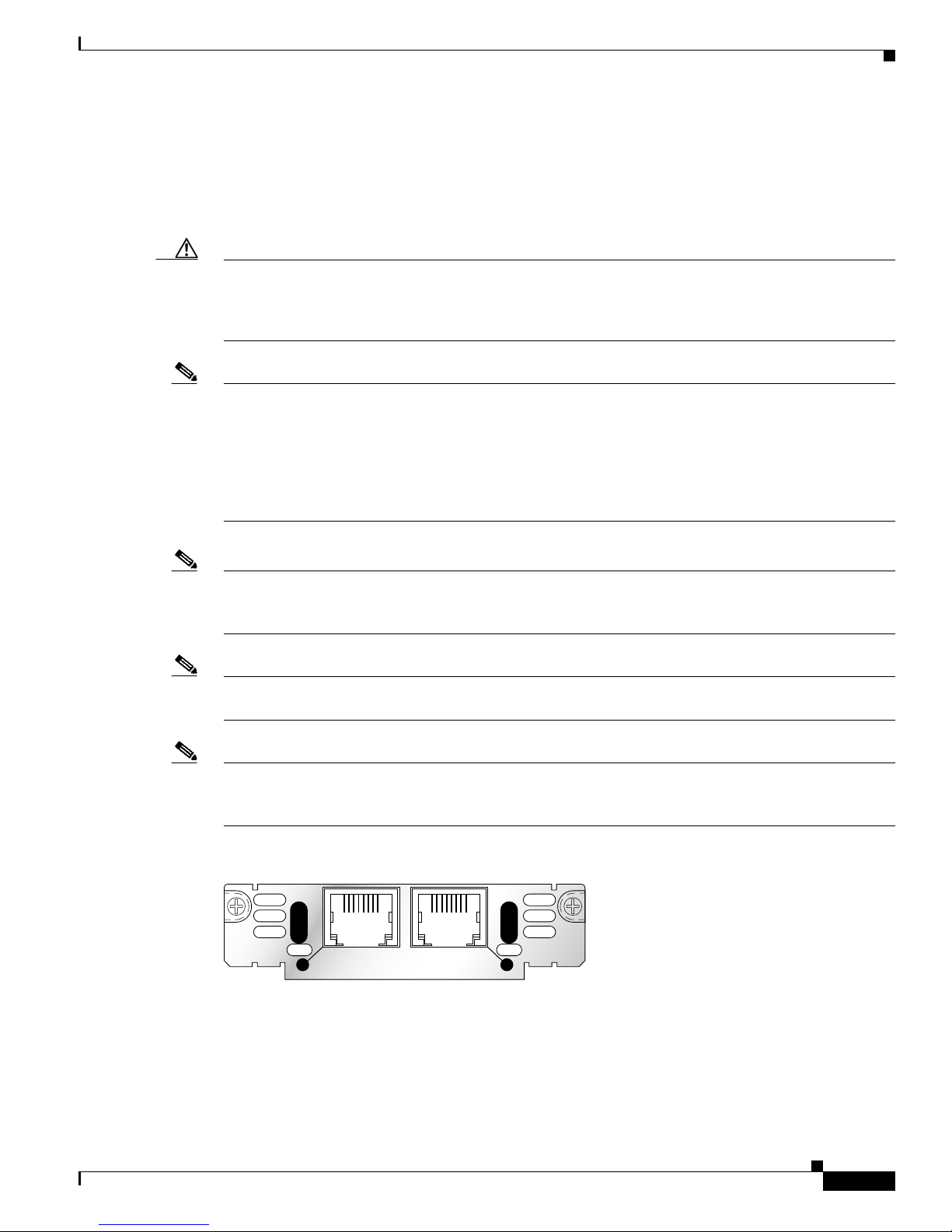
Figure 1 2-Port FXS Card Front Panel (VIC-2FXS)
VIC
FXS
IN USE
1 0
SEE MANUAL BEFORE INSTALLATION
IN USE
41218
OL-12847-01
3
Page 4

Foreign Exchange Station (FXS) Interface Cards
Figure 2 2-Port FXS Card Front Panel (VIC2-2FXS)
Connecting Voice Interface Cards to the Network
VIC22FXS
Figure 3 4-Port FXS/DID Card Front Panel (VIC-4FXS/DID)
VIC
4FXS/DID
3 2 1 0
Connecting FXS Cards
Use a standard straight-through RJ-11 modular telephone cable to connect a VIC-2FXS,
VIC-4FXS/DID, or VIC2-2FXS to a telephone or fax machine.
Warning
This equipment contains a ring signal generator (ringer), which is a source of hazardous voltage. Do
not touch the RJ-11 (phone) port wires (conductors), the conductors of a cable connected to the RJ-11
port, or the associated circuit-board when the ringer is active. The ringer is activated by an incoming
call.
IN USE
SEE MANUAL BEFORE INSTALLATION
IN USE
01
IN USE
!
89041
65683
Warning
For connections outside the building where the equipment is installed, the following ports must be
connected through an approved network termination unit with integral circuit protection: FXS.
Note Ports on this interface card are colored gray.
Step 1 Confirm that the router is still turned off.
Step 2 Connect one end of the straight-through RJ-11 cable to an RJ-11 port on the card. (See Figure 4.)
OL-12847-01
4
Page 5
Connecting Voice Interface Cards to the Network
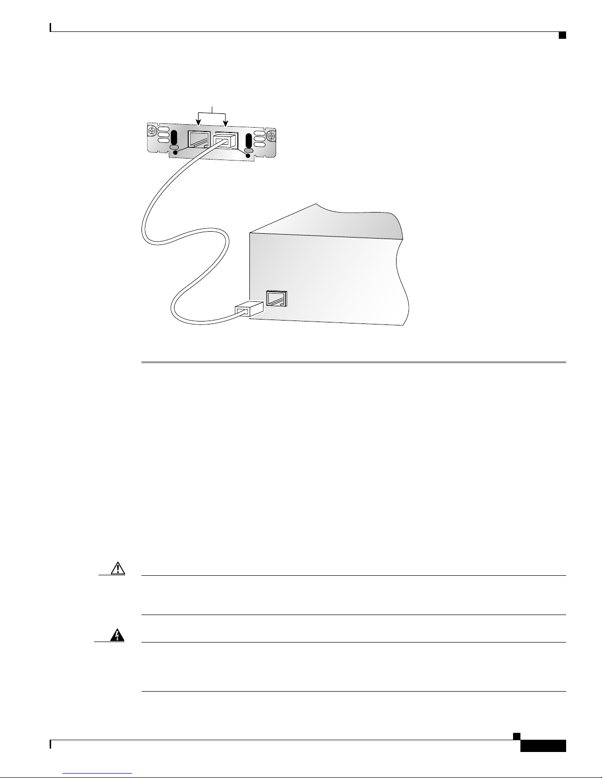
Figure 4 Connecting an FXS Card
RJ-11 ports
VIC
IN USE
FXS
1
SEE MANUAL BEFORE INSTALLATION
Straight-through
RJ-11-to-RJ-11 cable
Foreign Exchange Office (FXO) Interface Cards
IN USE
0
41197
Step 3
Fax machine
Connect the other end of the cable to the RJ-11 port on the telephone or fax machine.
Foreign Exchange Office (FXO) Interface Cards
A Foreign Exchange Office (FXO) interface connects local calls to a central office or PBX. This is the
interface a standard telephone provides. This type of card is illustrated in Figure 5, Figure 6, and
Figure 7.
The VIC-2FXO and VIC-2FXO-M1 interface cards are intended for use in North America (United
States, Canada, and Mexico).
The VIC-2FXO-EU and VIC-2FXO-M2 interface cards are intended for use in Europe.
The VIC-2FXO-M3 interface card is intended for use in Australia.
The VIC2-2FXO and VIC2-4FXO interface cards are software-configurable for all regions (see Figure 6
and Figure 7).
Caution To comply with the Telcordia GR-1089 NEBS standard for electromagnetic compatibility and safety,
connect the 2-port FXO card (VIC2-2FXO) only to intra-building or non-exposed wiring or cabling. The
intrabuilding cable must be shielded and the shield must be grounded at both ends.
Warning
This equipment contains a ring signal generator (ringer), which is a source of hazardous voltage. Do
not touch the RJ-11 (phone) port wires (conductors), the conductors of a cable connected to the RJ-11
port, or the associated circuit-board when the ringer is active. The ringer is activated by an incoming
call.
OL-12847-01
5
Page 6
Foreign Exchange Office (FXO) Interface Cards
Connecting Voice Interface Cards to the Network
Warning
For connections outside the building where the equipment is installed, the following ports must be
connected through an approved network termination unit with integral circuit protection.
FXO
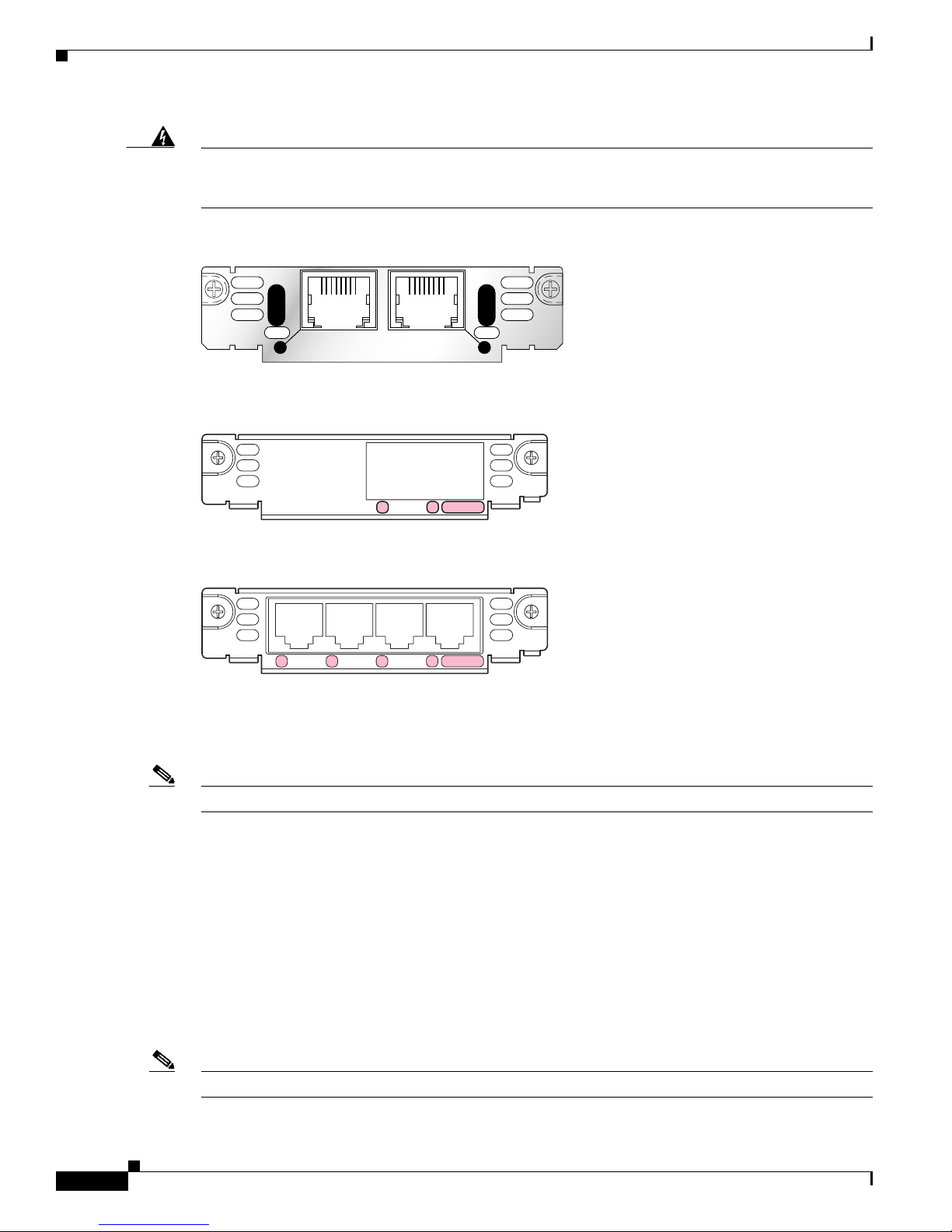
Figure 5 2-Port FXO Card Front Panel (VIC-2FXO)
VIC
FXO
IN USE
1 0
SEE MANUAL BEFORE INSTALLATION
IN USE
41217
Figure 6 2-Port FXO Card Front Panel (VIC2-2FXO)
SEE MANUAL
VIC22FXO
BEFORE INSTALLATION
1
0
IN USE
89038
Figure 7 4-Port FXO Card Front Panel (VIC2-4FXO)
VIC24FXO
23
1
0
IN USE
Setting Jumpers on the 2-Port FXO Card
Note This information does not apply to the VIC2-2FXO card.
The FXO voice interface card includes two jumper headers, W3 and W4, to set loop-start or ground-start
mode. One jumper configures each FXO port. The default setting is loop-start, which should be
satisfactory in most installations. In this setting, jumpers are placed over positions 2 and 3 of headers
W3 and W4.
Most modern central office equipment, such as DMS-100 and 5ESS switches, provides calling party
control (CPC) and Ring on Seize on loop-start lines. CPC allows quicker disconnection, and Ring on
Seize minimizes glare (collision of inbound and outbound calls on the same interface).
If your central office does not provide these features on loop-start, you may want to configure the FXO
card for ground-start operation instead by moving the jumpers to positions 1 and 2.
For proper operation, both jumpers on the VIC-2FXO card must be configured identically.
Note This setting does not apply to VIC-2FXO-EU and VIC-2FXO-M2 interface cards.
89040
OL-12847-01
6
Page 7
Connecting Voice Interface Cards to the Network
Connecting FXO Cards
Use a straight-through RJ-11 cable to connect the FXO voice interface card to the PSTN or PBX through
a telephone wall outlet.
Note Ports on this interface card are colored pink.
Step 1 Confirm that the router is still turned off.
Step 2 Connect one end of the straight-through RJ-11 cable to an RJ-11 port on the card. (See Figure 8.)
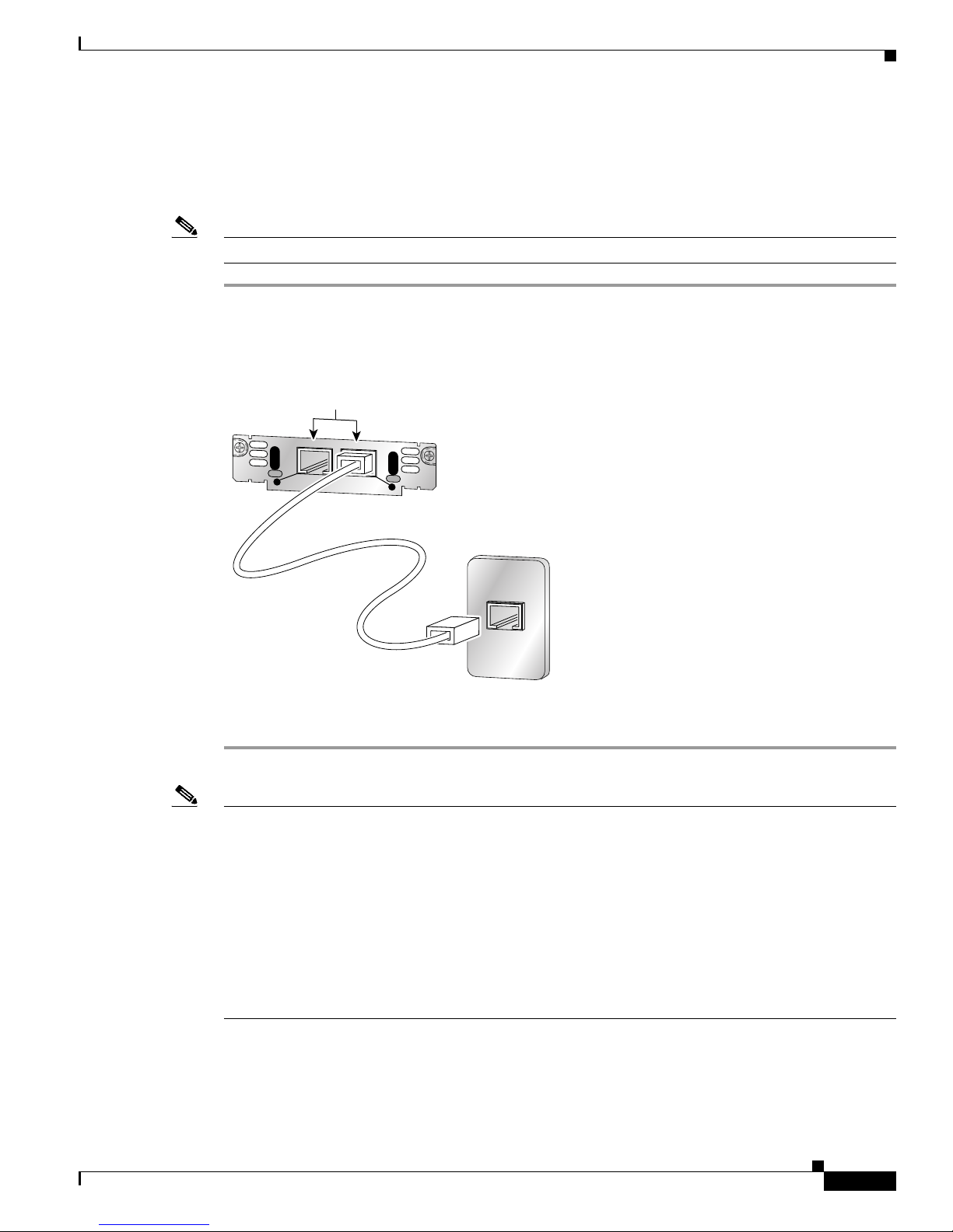
Figure 8 Connecting an FXO Card
RJ-11 ports
VIC
IN USE
FXS
1
SEE MANUAL BEFORE INSTALLATION
Foreign Exchange Office (FXO) Interface Cards
IN USE
0
Straight-through
RJ-11-to-RJ-11 cable
41195
RJ-11 wall jack
Step 3 Connect the other end to an RJ-11 telephone wall outlet.
Note If you have specified the use of a private line automatic ringdown (PLAR) off-premises extension (OPX)
connection mode for an FXO voice port (with loop resistance less than 8000 Ohm), you must ensure
that the soft-offhook option is enabled on the port.
This option allows a stepped offhook resistance during seizure which avoids overloading the circuit
during offhook in the event that ringing voltage is present on the circuit at the same time as the trunk
seizure. The stepped offhook resistance is initially set to 800 Ohms, then adjusts to 50 Ohms when
ringing voltage is not present.
To ena b l e soft-offhook command on the port, and to access the connection command with plar opx
syntax, see the Cisco Command Lookup Tool.
OL-12847-01
7
Page 8

Connecting Voice Interface Cards to the Network
Receive and Transmit (E&M) Interface Cards
Receive and Transmit (E&M) Interface Cards
RecEive and transMit (E&M) is a signaling technique for two-wire and four-wire telephone and trunk
interfaces. The E&M interface typically connects remote calls from an IP network to a PBX. The cards
are illustrated in Figure 9 and Figure 10.
Caution To comply with the Telcordia GR-1089 NEBS standard for electromagnetic compatibility and safety,
connect the 2-port E&M card (VIC2-2E/M) only to intra-building or non-exposed wiring or cabling. The
intrabuilding cable must be shielded and the shield must be grounded at both ends.
Figure 9 2-Port E&M Card Front Panel (VIC-2E/M)
VIC
E&M
IN USE
1 0
SEE MANUAL BEFORE INSTALLATION
Figure 10 2-Port E&M Card Front Panel (VIC2-2E/M)
VIC22E/M
IN USE
1
SEE MANUAL BEFORE INSTALLATION
Connecting E&M Interface Cards
Use a straight-through RJ-48C cable to connect the E&M card to the PSTN or PBX through a telephone
wall outlet.
Caution Do not connect an E&M interface directly to the PSTN.
Note Ports on the E&M voice interface card are colored brown.
IN USE
0
IN USE
41219
89039
Step 1 Confirm that the router is still turned off.
Step 2 Connect one end of the straight-through RJ-48C-to-RJ-48C cable to an RJ-48C port on the card. (See
Figure 11.)
OL-12847-01
8
Page 9

Connecting Voice Interface Cards to the Network
Figure 11 Connecting the 2-Port E&M Card
RJ-48C ports
VIC
IN USE
E&M
1
SEE MANUAL BEFORE INSTALLATION
Straight-through
RJ-48C-to-RJ-48C cable
FXS, FXO, and E&M Interface Card LEDs
IN USE
0
41194
RJ-48C wall jack
Step 3
Connect the other end of the cable to an RJ-48C wall outlet.
FXS, FXO, and E&M Interface Card LEDs
Each voice interface card has IN USE LEDs, one for each port. These LEDs have three states: green
when active, off when ready for use, and amber when not ready for use. Figure 12 shows a voice interface
card with an E&M interface as an example.
Figure 12 Voice Interface Card LEDs
VIC
E&M
IN USE
1 0
SEE MANUAL BEFORE INSTALLATION
LED LED
IN USE
ISDN BRI Interface Cards
41227
The ISDN BRI S/T voice interface card provides a client-side (TE) ISDN S/T physical interface for
connection to an NT1 device terminating an ISDN telephone network. Each port on the interface card
can carry two voice calls (one over each ISDN B channel), for a total of four calls per ISDN BRI card.
ISDN BRI NT/TE voice interface cards (VIC-2BRI-NT/TE and VIC2-2BRI-NT/TE) have the same
capabilities as the S/T card, but can also be configured to provide a network termination (NT) interface
with phantom power.
OL-12847-01
9
Page 10

ISDN BRI Interface Cards
Caution To comply with the Telcordia GR-1089 NEBS standard for electromagnetic compatibility and safety,
Connecting Voice Interface Cards to the Network
The Cisco 1751 and Cisco 1760 routers, and the Cisco ICS 7750 platform support both ISDN BRI
NT/TE voice interface cards. You can install these cards in any interface card slot in these platforms.
These platforms do not support the ISDN BRI S/T voice interface card.
The ISDN BRI NT/TE cards are illustrated in Figure 13 and Figure 14.
connect the 2-port ISDN BRI card (VIC2-2BRI-NT/TE) only to intra-building or non-exposed wiring or
cabling. The intrabuilding cable must be shielded and the shield must be grounded at both ends.
Figure 13 2-Port ISDN BRI Card Front Panel (VIC-2BRI-NT/TE)
RJ-48C ports
VIC
2B-NT/TE
ISDN BRI S/T 1
Figure 14 2-Port ISDN BRI Card Front Panel (VIC2-2BRI-NT/TE)
VIC22BRI-NT/TE
ISDN BRI S/T 1 ISDN BRI S/T 0
ISDN BRI Card Considerations
Note Cisco ISDN BRI interface cards support voice ISDN traffic only.
Note The ISDN BRI restrictions in this section do not apply to the VIC2-2BRI-NT/TE voice interface cards.
B1
B2
OK
B1
B2
OK
ISDN BRI S/T 0
SEE
MANUAL
BEFORE
INSTALLATION
SEE
MANUAL
BEFORE
INSTALLATION
35573
89037
Note The ISDN BRI restrictions in this section do not apply to the Cisco 1751, Cisco 1760, or Cisco ICS 7750
platforms.
To use all four voice channels, you must install the ISDN BRI card in slot 0 of a two-slot voice network
module (NM-2V). Slot 1 should remain empty.
Note If slot 0 is unoccupied, the system treats it as a pair of analog voice ports.
OL-12847-01
10
Page 11

Connecting Voice Interface Cards to the Network
If you install any of the following configurations, the Cisco IOS software disables certain ports, as shown
in Table 1 :
• An ISDN BRI voice interface card in a 1-slot voice network module (NM-1V)
• Two ISDN BRI voice interface cards in a 2-slot voice network module (NM-2V)
• One ISDN BRI voice interface card and one analog voice interface card (VIC-2FXS, VIC-2FXO,
VIC-2FXO-EU, VIC-2FXO-M3, or VIC-2E/M) in a 2-slot voice network module (NM-2V)
Table 1 How Cisco IOS Software Handles Voice Interface Card Ports
Network Module Slot Voice Interface Card Port Status
NM-1V 0 VIC-2BRI-S/T-TE,
NM-2V 0 VIC-2BRI-S/T-TE,
NM-2V 0 VIC-2BRI-S/T-TE,
NM-2V 0 VIC-2BRI-S/T-TE,
NM-2V 0 Analog voice interface card 0 Up
ISDN BRI Interface Cards
0Up
VIC-2BRI-NT/TE
VIC-2BRI-NT/TE
VIC-2BRI-NT/TE
1 VIC-2BRI-S/T-TE,
VIC-2BRI-NT/TE
VIC-2BRI-NT/TE
1 Analog voice interface card 0 Down
1 VIC-2BRI-S/T-TE,
VIC-2BRI-NT/TE
1 Down
0Up
1Up
0Up
1Up
0 Down
1 Down
0Up
1Up
1 Down
1Up
0Up
1 Down
Connecting ISDN BRI Interface Cards
Use a straight-through RJ-45 cable to connect ISDN BRI cards to the ISDN network through a telephone
wall outlet or other device.
Caution To prevent damage to the router, be sure to connect the BRI cable to the BRI connector only, and not to
any other RJ-45 connector.
To connect the 2-port ISDN BRI card to the router, follow these steps:
Step 1 Confirm that the router is still turned off.
Step 2 Connect one end of a straight-through RJ-45-to-RJ-45 cable to the RJ-45 port on the card. (See
Figure 15.)
OL-12847-01
11
Page 12

ISDN BRI Interface Cards
Connecting Voice Interface Cards to the Network
Figure 15 Connecting the 2-Port ISDN BRI Card
RJ-45 ports
VIC
2B-S/T TE
ISDN BRI S/T 1
B1
B2
OK
ISDN BRI S/T 0
SEE
MANUAL
BEFORE
INTALLATION
Straight-through
RJ-45-to-RJ-45 cable
41198
NT1 device
S/T port
Note When the interface is configured as NT and is connecting to a TE device, the cable must have
the transmit and receive pins swapped (crossover cable). See Table 2.
Table 2 Interface Pin Numbers and Functions
ISDN BRI NT/TE Card NT Interface
1
TE Interface
Pin 3/T+ Pin 3/R+ Pin 3/T+
Pin 4/R+ Pin 4/T+ Pin 4/R+
Pin 5/R- Pin 5/T- Pin 5/R-
Pin 6/T- Pin 6/R- Pin 6/T-
1. Use a straight-through cable for NT interfaces.
2. Use a crossover cable for TE interfaces.
Step 3 Connect the other end of the cable to the RJ-45 wall outlet or other device.
2
OL-12847-01
12
Page 13

Connecting Voice Interface Cards to the Network
Analog Direct Inward Dial (DID) Interface Cards
ISDN BRI Interface Card LEDs
ISDN BRI voice interface cards have three LEDs, as listed in Table 3 .
Table 3 ISDN BRI Voice Interface Card LEDs
LED Meaning
B1 Call active on B1 channel
B2 Call active on B2 channel
OK Interface is connected to an ISDN network
Analog Direct Inward Dial (DID) Interface Cards
A Direct Inward Dial (DID) voice interface provides DID service to extensions on a PBX. Figure 16
shows the VIC-2DID card, and Figure 17 shows the VIC-4FXS/DID card.
Caution To comply with the Telcordia GR-1089 NEBS standard for electromagnetic compatibility and safety,
connect the 4-port FXS/DID card (VIC-4FXS/DID) only to intra-building or non-exposed wiring or
cabling. The intrabuilding cable must be shielded and the shield must be grounded at both ends.
Note Each port on the 4-port FXS/DID VIC can be configured as either Foreign Exchange Station (FXS) or
Direct Inward Dial (DID) when it is used with phones with a Ringer Equivalence Number (REN) load
of 1 or less.
If the REN load on any port is greater than 1, all four ports must be configured as either FXS or DID.
For information about using FXS with the 4-port FXS/DID VIC, see the “Foreign Exchange Station
(FXS) Interface Cards” section on page 3.
Note Cisco 2600XM series, Cisco 2691, Cisco 2800 series, Cisco 3600 series, Cisco 3700 series, and
Cisco 3800 series routers support DID on the 4-port FXS/DID cards in Cisco IOS Release 12.3(14)T and
later.
Figure 16 2-Port Analog DID Voice Interface Card
VIC
2DID
IN USE
1 0
SEE MANUAL BEFORE INSTALLATION
IN USE
36014
OL-12847-01
13
Page 14

Analog Direct Inward Dial (DID) Interface Cards
Figure 17 4-Port Analog FXS/DID Voice Interface Card
VIC
4FXS/DID
3 2 1 0
IN USE
Connecting an Analog DID Interface Card
Use a standard straight-through RJ-11 modular telephone cable to connect the VIC-2DID or
VIC-4FXS/DID interface card to a PSTN or PBX.
Step 1 Install the grounding lug on the router. See the hardware installation guide for your router for detailed
instructions. (Grounding on the Cisco 1700 series routers is done on the router chassis, and does not need
a grounding lug.)
Step 2 Confirm that the router is still turned off.
Connecting Voice Interface Cards to the Network
65683
Step 3 Connect one end of the straight-through RJ-11 cable to an RJ-11 port on the card. (See Figure 18.)
Figure 18 Connecting an Analog DID Interface Card
RJ-11 ports
VIC
IN USE
DID
1
SEE MANUAL BEFORE INSTALLATION
IN USE
0
Straight-through
RJ-11-to-RJ-11 cable
36015
RJ-11 wall jack
Caution The VIC-2DID or the VIC-4FXS/DID interface cards may be damaged if connected to a standard PSTN
line. Ensure that lines to the PSTN are provisioned for DID.
Step 4 Connect the other end of the cable to a telephone wall outlet or to a PBX.
OL-12847-01
14
Page 15

Connecting Voice Interface Cards to the Network
Multiflex Trunk Interface Cards
Multiflex trunk interface cards support generic 1- or 2-port T1 or E1 trunk interfaces for voice, data, and
integrated voice and data applications. These cards provide basic structured and unstructured service for
T1 or E1 networks.
They can be used as trunk interfaces for voice and data services, as fractional n x 64-kbps service for
WANs (Frame Relay or leased line), or for time-division multiplexing (TDM) drop-and-insert (voice and
data integration) services.
Multiflex trunk interface cards provide voice and data access to the PSTN domain through TDM ports,
and include an integrated channel service unit/data service unit (CSU/DSU).
Some 2-port multiflex trunk interface cards also support the drop-and-insert process, which adds data to
a T1 or E1 data stream, or terminates data from a T1 or E1 data stream to other devices connected to the
drop-and-insert equipment.
Caution When both ports on a VWIC-2MFT-T1, VWIC-2MFT-E1, VWIC-2MFT-G703, or VWIC-2MFT-E1-DI
interface card are configured as clock source line, then they must be set to the same clock source. If they
are not set to the same clock source, timing slips can occur. Each port on the VWIC2-2MFT-T1/E1 and
VWIC2-2MFT-G703 interface cards can be set to independent clock sources for data applications.
Multiflex Trunk Interface Cards
Caution To comply with the Telcordia GR-1089 NEBS standard for electromagnetic compatibility and safety,
connect the VWIC-2MFT-G703 only to intra-building or non-exposed wiring or cabling. The
intrabuilding cable must be shielded and the shield must be grounded at both ends.
Caution To comply with the Telcordia GR-1089 NEBS standard for electromagnetic compatibility and safety,
connect the VWIC2-2MFT-T1/E1, VWIC2-1MFT-T1/E1, VWIC2-1MFT-G703, VWIC2-2MFT-G703
ports only to intra-building or nonexposed wiring or cabling. The intrabuilding cable must be shielded
and the shield must be grounded at both ends. The intra-building port(s) of the equipment or
subassembly must not be metallically connected to interfaces that connect to the OSP or its wiring. These
interfaces are designed for use as intra-building interfaces only (Type 2 or Type 4 ports as described in
GR-1089-CORE, Issue 4) and require isolation from the exposed OSP cabling. The addition of Primary
Protectors is not sufficient protection in order to connect these interfaces metallically to OSP wiring.
This section describes the following multiflex trunk interface cards:
• 1-port T1 multiflex trunk interface card (VWIC-1MFT-T1)
• 2-port T1 multiflex trunk interface card (VWIC-2MFT-T1)
• 1-port E1 multiflex trunk interface card (VWIC-1MFT-E1)
• 2-port E1 multiflex trunk interface card (VWIC-2MFT-E1)
• 1-port E1 multiflex trunk interface card with G.703 support (VWIC-1MFT-G703)
• 2-port E1 multiflex trunk interface card with G.703 support (VWIC-2MFT-G703)
• 2-port T1 multiflex trunk interface card with drop-and-insert capability (VWIC-2MFT-T1-DI)
• 2-port E1 multiflex trunk interface card with drop-and-insert capability (VWIC-2MFT-E1-DI)
• 1-port T1/E1 multiflex trunk interface card (VWIC2-1MFT-T1/E1)
• 2-port T1/E1 multiflex trunk interface card (VWIC2-2MFT-T1/E1)
OL-12847-01
15
Page 16

Multiflex Trunk Interface Cards
• 1-port E1 multiflex trunk interface card with G.703 support (VWIC2-1MFT-G703)
• 2-port multiflex trunk interface card with G.703 support (VWIC2-2MFT-G703)
The following multiflex trunk interface cards provide hardware echo cancellation features through an
echo canceler expansion module, installed on the main board of the interface card:
• VWIC2-1MFT-T1/E1
• VWIC2-2MFT-T1/E1
• VWIC2-1MFT-G703
Connecting Voice Interface Cards to the Network
Note The VWIC2-1MFT-T1/E1 and VWIC2-2MFT-T1/E1 interface cards are configurable for T1
or E1 service and drop- and insert-capability.
Note The VWIC-1MFT-G703, VWIC2-1MFT-G703, VWIC-2MFT-G703 and
VWIC2-2MFT-G703 interface cards allow unstructured E1 traffic that conforms to the
ITU-T G.703 standard.
• VWIC2-2MFT-G703
The following expansion modules are available:
• 32-channel echo canceler module for multiflex trunk (EC-MFT-32)
• 64-channel echo canceler module for multiflex trunk (EC-MFT-64)
For information on echo canceler expansion module installation, see the Installing Echo Canceler
Expansion Modules on Cisco Interface Cards document.
See Figure 19 for a sample 1-port multiflex trunk interface card, and Figure 20 for a sample 2-port
multiflex trunk interface card.
Figure 19 1-Port T1/E1 Multiflex Trunk Interface Card Faceplate (VWIC-1MFT-T1)
RJ-48C port
AL
VWIC
1MFT-T1
LP
CD
CTRLR T1 0
Figure 20 2-Port T1/E1 Multiflex Trunk Interface Card Faceplate (VWIC-2MFT-T1)
RJ-48C ports
SEE
MANUAL
BEFORE
INSTALLATION
41232
VWIC
2MFT-T1
OL-12847-01
CTRLR T1 1
16
AL
LP
CD
CTRLR T1 0
SEE
MANUAL
BEFORE
INSTALLATION
41230
Page 17

Connecting Voice Interface Cards to the Network
Multiflex Trunk Interface Card LEDs
Multiflex trunk interface cards have three LEDs, which are shown in Figure 19 and Figure 20 and are
described in Table 4.
Table 4 Multiflex Trunk Interface Card LEDs
LED Description Color
LP LED A loopback or line state is detected or is manually set by the
user. This LED is off during normal operation.
AL LED A local or remote alarm state exists. This LED is off during
normal operation.
CD LED A carrier has been detected, and the internal DSU/CSU in the
interface card is communicating with another DSU/CSU. This
LED is on during normal operation.
Connecting a Multiflex Trunk Interface Card
Multiflex Trunk Interface Cards
Yellow
Yellow
Green
For this connection, use the straight-through RJ-48C-to-RJ-48C cable that came with your card.
Note See Cisco Modular Access Router Specifications for network-end connectors and pinouts of the cables
connecting voice cards. Look under the type of interface card.
Confirm that the router is turned off.
Step 5 Connect one end of the straight-through RJ-48C-to-RJ-48C cable to the T1 or E1 port on the card. (See
Figure 21.)
Figure 21 Connecting a Multiflex Trunk Interface Card
RJ-48C ports
AL
VWIC
2MFT-E1-D1
CTRLR E1 1
LP
CD
Straight-through
RJ-48C-to-RJ-48C cable
CTRLR E1 0
SEE
MANUAL
BEFORE
INSTALLATION
Step 6
Connect the other end to the T1 or E1 wall jack (RJ-48C) at your site.
Step 7 Turn on power to the router.
41202
RJ-48C wall jack
OL-12847-01
17
Page 18

Connecting Voice Interface Cards to the Network
Centralized Automated Message Accounting Trunk Protocol Interface Cards
Step 8 Check that the CD LED comes on, which means that the card’s internal DSU/CSU is communicating
with the DSU/CSU at the T1 or E1 service provider central office.
Centralized Automated Message Accounting Trunk Protocol
Interface Cards
The Centralized Automated Message Accounting (CAMA) trunk protocol interface connects local calls
to emergency services. The CAMA card provides the software features required to connect directly to
the enhanced 911 (E911) network from the customer premises. It also provides direct connections to a
Public Service Answering Point (PSAP) using analog CAMA trunks. The CAMA protocol provides
in-band signaling.
Note For the NM-HD-1V, NM-HD-2V, and NM-HD-2VE voice network modules, and for the Cisco 1751 and
1760 routers, CAMA is supported by the VIC2-2FXO interface card. The VIC-2CAMA card cannot be
used with the NM-HD-1V, NM-HD-2V, or NM-HD-2VE voice network modules, or with the Cisco 1751
or Cisco 1760 routers.
CAMA Interface Cards
The 2-port CAMA card is illustrated in Figure 22.
Figure 22 V2-Port CAMA Card Front Panel (VIC-2CAMA)
VIC-
2CAMA
Connecting the CAMA Interface Card
Use a straight-through RJ-11 cable to connect the VIC-2CAMA voice interface card to the PSTN or PBX
through a telephone wall outlet.
Note Ports on this interface card are colored pink.
Step 1 Confirm that the router is still turned off.
Step 2 Connect one end of the straight-through RJ-11 cable to an RJ-11 port on the card. (See Figure 23.)
IN USE
1 0
SEE MANUAL BEFORE INSTALLATION
IN USE
62331
OL-12847-01
18
Page 19

Connecting Voice Interface Cards to the Network
Figure 23 Connecting the 2-Port CAMA Card
RJ-11 ports
VIC-
IN USE
2CAMA
1
SEE MANUAL BEFORE INSTALLATION
Straight-through
RJ-11-to-RJ-11 cable
Related Documentation
IN USE
0
62330
RJ-11 wall jack
Step 3
Connect the other end of the cable to the telephone wall outlet (RJ-11 port).
Related Documentation
For additional information, see the following documents and resources.
• Low Density Voice/Fax Network Modules for the Cisco 2600, 3600 and 3700 Series Routers,
data sheet
• Understanding Direct Inward Dial (DID) Voice Interface Cards, tech note
• Voice Hardware Compatibility Matrix (Cisco 17xx, 26/36/37xx, VG200, Catalyst 4500/4000,
Catalyst 6xxx), tech note
• Cisco 4-Port High-Density FXS/DID Analog Voice Interface Card for the Cisco 1700 Series
Modular Access Routers, data sheet
• Digital J1 Packet Voice Network Module, data sheet
• FXO, FXS, and E&M Voice Interface Card Support on Cisco 1700 Series Routers
• Understanding 1-Port and 2-Port E1 Multiflex Trunk Voice/WAN Interface Cards (VWICs), tech note
• Cisco Digital 1-port and 2-port T1 Multi-Flex Voice WICs, tech note
• Cisco T1/E1 Multiflex Voice/WAN Interface Cards for the Cisco 1700 Series Modular Access
Routers, data sheet
• Understanding E&M Voice Interface Cards, tech note
• Analog E&M Voice Signaling Overview, tech note
• Understanding and Troubleshooting Analog E & M Interface Types and Wiring Arrangements, tech
note
• Understanding and Troubleshooting Analog E&M Start Dial Supervision Signaling, tech note
• E&M Cable Pinouts to Connect Cisco 1750/2600/3600 E&M VIC to Nortel PBX Option 11 E&M
Trunk, tech note
OL-12847-01
19
Page 20

Related Documentation
Connecting Voice Interface Cards to the Network
• E&M Cable Pinouts Connecting Cisco 1750/2600/3600 E&M VIC to Lucent PBX G3R E&M Trunk,
tech note
• Cisco Network Modules and Interface Cards Regulatory Compliance and Safety Information
• Analog DID for Cisco 2600 and Cisco 3600 Series Routers, Cisco IOS Release 12.2(2)T feature
module
• Voice Software Enhancements for the Cisco 1750 and Cisco 1751 Routers, configuration note
• Configuring and Troubleshooting the VIC-2DID, how-to
• Analog DID for Cisco 2600 and Cisco 3600 Series Routers, Cisco IOS Release 12.1(5)XM feature
module
• 4-Port FXS/DID Voice Interface Card Support on the Cisco 1751 and Cisco 1760 Routers,
configuration note
• Installing and Configuring the 1-Port Digital J1 Voice Interface Cards
• T1/E1 Multiflex VWIC Enhancements, Cisco IOS Release 12.1(3)T feature module
• G.703 Configuration for Multiflex Voice/WAN Interface Cards on Cisco 2600 and 3600 Series
Routers, Cisco IOS Release 12.1(1)T feature module
• Configuring 1- and 2-Port T1/E1 Multiflex Voice/WAN Interface Cards on Cisco 2600 and 3600
Series Routers, Cisco IOS Release 12.0(7)T feature module
• Analog Centralized Automatic Message Accounting E911 Trunk
• Configuring 2-Port ISDN BRI Voice Interface Cards for the Cisco 1751 and Cisco 1760 Routers,
configuration note
• Cisco IOS ISDN Voice Configuration Guide, Release 12.3
• “VoIP Configuration” chapter in the Cisco 1751 Router Software Configuration Guide
• Understanding One Stage and Two Stage Voice Dialing, tech note
• Structured CES Using Synchronous Clocking and PVCs in a Cisco 3600 Platform, sample
configuration
• Unstructured CES with Synchronous Clocking and PVCs on a 3600 Platform, tech note
• Using Analog E&M Ports to Interface to Overhead Paging Systems, sample configuration
• Configuring Connection Trunk for VoIP Gateways, sample configuration
• “Troubleshooting Analog Voice Interfaces to the IP Network” chapter of the Cisco IOS Voice
Troubleshooting and Monitoring Guide
• Configuring and Troubleshooting the VIC-2DID, how-to
• Ringing and Idle Voltages on Cisco FXS Interfaces, tech note
• Analog E&M Troubleshooting Guidelines (Cisco IOS Platforms), tech note
• Understanding and Troubleshooting Analog E&M Start Dial Supervision Signaling, tech note
• Understanding and Troubleshooting Analog E & M Interface Types and Wiring Arrangements,
tech note
OL-12847-01
20
Page 21

Connecting Voice Interface Cards to the Network
Obtaining Documentation, Obtaining Support, and Security Guidelines
Obtaining Documentation, Obtaining Support, and Security
Guidelines
For information on obtaining documentation, obtaining support, providing documentation feedback,
security guidelines, and also recommended aliases and general Cisco documents, see the monthly
What’s New in Cisco Product Documentation, which also lists all new and revised Cisco technical
documentation, at:
http://www.cisco.com/en/US/docs/general/whatsnew/whatsnew.html
CCDE, CCENT, CCSI, Cisco Eos, Cisco HealthPresence, Cisco IronPort, the Cisco logo, Cisco Nurse Connect, Cisco Pulse, Cisco SensorBase,
Cisco StackPower, Cisco StadiumVision, Cisco TelePresence, Cisco Unified Computing System, Cisco WebEx, DCE, Flip Channels, Flip for Good,
Flip Mino, Flipshare (Design), Flip Ultra, Flip Video, Flip Video (Design), Instant Broadband, and Welcome to the Human Network are trademarks;
Changing the Way We Work, Live, Play, and Learn, Cisco Capital, Cisco Capital (Design), Cisco:Financed (Stylized), Cisco Store, Flip Gift Card,
and One Million Acts of Green are service marks; and Access Registrar, Aironet, AllTouch, AsyncOS, Bringing the Meeting To You, Catalyst, CCDA,
CCDP, CCIE, CCIP, CCNA, CCNP, CCSP, CCVP, Cisco, the Cisco Certified Internetwork Expert logo, Cisco IOS, Cisco Lumin, Cisco Nexus,
Cisco Press, Cisco Systems, Cisco Systems Capital, the Cisco Systems logo, Cisco Unity, Collaboration Without Limitation, Continuum, EtherFast,
EtherSwitch, Event Center, Explorer, Follow Me Browsing, GainMaker, iLYNX, IOS, iPhone, IronPort, the IronPort logo, Laser Link, LightStream,
Linksys, MeetingPlace, MeetingPlace Chime Sound, MGX, Networkers, Networking Academy, PCNow, PIX, PowerKEY, PowerPanels, PowerTV,
PowerTV (Design), PowerVu, Prisma, ProConnect, ROSA, SenderBase, SMARTnet, Spectrum Expert, StackWise, WebEx, and the WebEx logo are
registered trademarks of Cisco Systems, Inc. and/or its affiliates in the United States and certain other countries.
All other trademarks mentioned in this document or website are the property of their respective owners. The use of the word partner does not imply
a partnership relationship between Cisco and any other company. (0910R)
Any Internet Protocol (IP) addresses used in this document are not intended to be actual addresses. Any examples, command display output, and
figures included in the document are shown for illustrative purposes only. Any use of actual IP addresses in illustrative content is unintentional and
coincidental.
© 2008 Cisco Systems, Inc. All rights reserved.
OL-12847-01
21
Page 22

Obtaining Documentation, Obtaining Support, and Security Guidelines
Connecting Voice Interface Cards to the Network
OL-12847-01
22
 Loading...