

Page 1

Cisco VG202, Cisco VG202XM,
Cisco VG204, and Cisco VG204XM
Voice Gateways Software Configuration
Guide
Americas Headquarters
Cisco Systems, Inc.
170 West Tasman Drive
San Jose, CA 95134-1706
USA
http://www.cisco.com
Tel: 408 526-4000
800 553-NETS (6387)
Fax: 408 527-0883
Text Part Number: OL-16191-01
Page 2

THE SPECIFICATIONS AND INFORMATION REGARDING THE PRODUCTS IN THIS MANUAL ARE SUBJECT TO CHANGE WITHOUT NOTICE. ALL
STATEMENTS, INFORMATION, AND RECOMMENDATIONS IN THIS MANUAL ARE BELIEVED TO BE ACCURATE BUT ARE PRESENTED WITHOUT
WARRANTY OF ANY KIND, EXPRESS OR IMPLIED. USERS MUST TAKE FULL RESPONSIBILITY FOR THEIR APPLICATION OF ANY PRODUCTS.
THE SOFTWARE LICENSE AND LIMITED WARRANTY FOR THE ACCOMPANYING PRODUCT ARE SET FORTH IN THE INFORMATION PACKET THAT
SHIPPED WITH THE PRODUCT AND ARE INCORPORATED HEREIN BY THIS REFERENCE. IF YOU ARE UNABLE TO LOCATE THE SOFTWARE LICENSE
OR LIMITED WARRANTY, CONTACT YOUR CISCO REPRESENTATIVE FOR A COPY.
The Cisco implementation of TCP header compression is an adaptation of a program developed by the University of California, Berkeley (UCB) as part of UCB’s public
domain version of the UNIX operating system. All rights reserved. Copyright © 1981, Regents of the University of California.
NOTWITHSTANDING ANY OTHER WARRANTY HEREIN, ALL DOCUMENT FILES AND SOFTWARE OF THESE SUPPLIERS ARE PROVIDED “AS IS” WITH
ALL FAULTS. CISCO AND THE ABOVE-NAMED SUPPLIERS DISCLAIM ALL WARRANTIES, EXPRESSED OR IMPLIED, INCLUDING, WITHOUT
LIMITATION, THOSE OF MERCHANTABILITY, FITNESS FOR A PARTICULAR PURPOSE AND NONINFRINGEMENT OR ARISING FROM A COURSE OF
DEALING, USAGE, OR TRADE PRACTICE.
IN NO EVENT SHALL CISCO OR ITS SUPPLIERS BE LIABLE FOR ANY INDIRECT, SPECIAL, CONSEQUENTIAL, OR INCIDENTAL DAMAGES, INCLUDING,
WITHOUT LIMITATION, LOST PROFITS OR LOSS OR DAMAGE TO DATA ARISING OUT OF THE USE OR INABILITY TO USE THIS MANUAL, EVEN IF CISCO
OR ITS SUPPLIERS HAVE BEEN ADVISED OF THE POSSIBILITY OF SUCH DAMAGES.
Cisco and the Cisco logo are trademarks or registered trademarks of Cisco and/or its affiliates in the U.S. and other countries. To view a list of Cisco trademarks, go to this
URL: www.cisco.com/go/trademarks. Third-party trademarks mentioned are the property of their respective owners. The use of the word partner does not imply a partnership
relationship between Cisco and any other company. (1110R)
Cisco VG202, Cisco VG202XM, Cisco VG204, and Cisco VG204XM Voice Gateways Software Configuration Guide
Copyright © 2008-2013 Cisco Systems, Inc. All rights reserved.
Page 3

Preface v
CONTENTS
CHAPTER
CHAPTER
1 Understanding Interface Numbering and Cisco IOS Software Basics 1-1
About the Voice Gateways 1-1
Port Numbering Conventions 1-1
Understanding Cisco IOS Software Basics 1-3
About Cisco IOS Software 1-3
Getting Help 1-4
Command Modes 1-4
Undoing a Command or Feature 1-5
Saving Configuration Changes 1-5
Upgrading to a New Cisco IOS Release 1-6
Typical Voice Gateway Deployment Scenario 1-6
Where to Go Next 1-6
2 Configuring Your Voice Gateway Using the setup Command 2-1
About Configuring Your Voice Gateway 2-1
Preparing to Configure Your Cisco Voice Gateway 2-1
Using the setup Command 2-2
CHAPTER
CHAPTER
OL-16191-01
Completing the Configuration 2-5
3 Configuring Your Voice Gateway Using the CLI 3-1
Configuring the Hostname and Password 3-1
Verifying the Hostname and Password 3-2
Configuring Fast Ethernet Interfaces 3-3
Saving Configuration Changes 3-5
4 Configuring Voice 4-1
Prerequisites 4-1
Configuring the Voice Interface 4-1
Auto-Configuration on the Cisco VG202, Cisco VG202XM, Cisco VG204, and Cisco VG204XM Voice
Gateways
4-3
Restriction for Configuring Auto-Configuration 4-3
Cisco VG202, Cisco VG202XM, Cisco VG204, and Cisco VG204XM Voice Gateways Software Configuration Guide
iii
Page 4

Contents
Auto-Configuration With a DHCP Server 4-3
Auto-Configuration Without a DHCP Server 4-5
Configuring the Voice Interface for Cisco Unified Communications Manager 4-7
Configuring the MAC Address Convention 4-10
Configuring Calls 4-11
Call Transfer 4-11
Call Waiting 4-12
Three-Party Conferencing 4-12
Caller ID 4-12
APPENDIX
I
NDEX
A Using the ROM Monitor A-1
Entering the ROM Monitor Mode A-1
About the ROM Monitor Commands A-2
Listing the ROM Monitor Commands A-3
Command Descriptions A-3
Recovering Boot and System Images A-4
Using the Configuration Register A-5
About Changing the Configuration Register A-5
Changing the Configuration Register Manually A-5
Changing the Configuration Register Using Prompts A-5
Using the Console Download Function A-6
About the Console Download Function A-6
Command Description A-6
Error Reporting A-7
Using Debug Commands A-7
Exiting the ROM Monitor Mode A-8
iv
Cisco VG202, Cisco VG202XM, Cisco VG204, and Cisco VG204XM Voice Gateways Software Configuration Guide
OL-16191-01
Page 5

Preface
This preface describes the objectives, audience, and conventions of this document, and where to get the
latest version of documentation.
• Document Objectives, page v
• Audience, page v
• Documentation Conventions, page vi
• Accessibility, page vi
• Related Documentation, page vii
• Obtaining Documentation and Submitting a Service Request, page vii
Document Objectives
After installing a Cisco VG202, Cisco VG202XM, Cisco VG204, or Cisco VG204XM voice gateway,
use this guide to complete a basic configuration. This guide also contains information on using the
Cisco IOS software to perform other configuration tasks, such as configuring a VoIP interface and other
features.
This guide does not provide complete configuration instructions. See the Cisco IOS configuration guides
and command references for detailed configuration instructions.
Audience
This document is designed for the person who will be responsible for configuring your voice gateway.
This guide is intended primarily for the following audiences:
• Customers with technical networking background and experience.
OL-16191-01
• System administrators who are familiar with the fundamentals of voice gateway-based
internetworking, but who might not be familiar with Cisco IOS software.
• System administrators who are responsible for installing and configuring internetworking
equipment, and who are familiar with Cisco IOS software.
Cisco VG202, Cisco VG202XM, Cisco VG204, and Cisco VG204XM Voice Gateways Software Configuration Guide
v
Page 6

Documentation Conventions
Table 1 Documentation Conventions
Convention Description
boldface font Commands and keywords.
italic font Variables for which you supply values.
[ ] Keywords or arguments that appear within square brackets are optional.
{x | y | z} A choice of required keywords appears in braces separated by vertical bars. You must select one.
screen font Examples of information displayed on the screen.
boldface screen
font
< > Nonprinting characters, for example passwords, appear in angle brackets in contexts where italic font is
[ ] Default responses to system prompts appear in square brackets.
Examples of information you must enter.
not available.
Note Means reader take note. Notes contain helpful suggestions or references to materials not contained in
this publication.
Timesaver Means the described action saves time. You can save time by performing the action described in the
paragraph.
Caution Means reader be careful. In this situation, you might do something that could result in equipment
damage or loss of data.
Tip Means the following information will help you solve a problem. The tips information might not be
troubleshooting or even an action, but could be useful information, similar to a Timesaver.
Accessibility
You can configure the Cisco VG202, Cisco VG202XM, Cisco VG204, and Cisco VG204XM voice
gateways by using the Cisco command-line interface (CLI). The CLI conforms to code 508 because it is
text based and relies on a keyboard for navigation. You can configure and monitor all functions of the
voice gateway through the CLI.
For a complete list of guidelines and Cisco products’ adherence to accessibility, see Cisco Accessibility
Products at the following URL:
http://www.cisco.com/web/about/responsibility/accessibility/products
vi
Cisco VG202, Cisco VG202XM, Cisco VG204, and Cisco VG204XM Voice Gateways Software Configuration Guide
OL-16191-01
Page 7

Related Documentation
The documents described here are available online. To be sure that you are obtaining the latest
information, you should access the online documentation.
To access online user documentation (in both PDF and HTML formats), go to Cisco.com. Under
Documentation, select Voice and Unified Communications, select Voice Gateway, and then select
Cisco VG200 Series Gateways.
• Cisco VG202, Cisco VG202XM, Cisco VG204, and Cisco VG204XM Voice Gateways Hardware
Installation Guide
• Cisco VG202, Cisco VG202XM, Cisco VG204, and Cisco VG204XM Voice Gateways Quick Start
Guide
• Cisco VG202, Cisco VG202XM, Cisco VG204, and Cisco VG204XM Voice Gateways Software
Configuration Guide (this document)
• Regulatory Compliance and Safety Information for the Cisco VG202, Cisco VG202XM,
Cisco VG204, and Cisco VG204XM Voice Gateways
Obtaining Documentation and Submitting a Service Request
For information on obtaining documentation, submitting a service request, and gathering additional
information, see the monthly What’s New in Cisco Product Documentation, which also lists all new and
revised Cisco technical documentation, at:
http://www.cisco.com/en/US/docs/general/whatsnew/whatsnew.html
Subscribe to the What’s New in Cisco Product Documentation as a Really Simple Syndication (RSS) feed
and set content to be delivered directly to your desktop using a reader application. The RSS feeds are a free
service and Cisco currently supports RSS version 2.0.
vii
Page 8

viii
Cisco VG202, Cisco VG202XM, Cisco VG204, and Cisco VG204XM Voice Gateways Software Configuration Guide
OL-16191-01
Page 9

Understanding Interface Numbering and Cisco IOS Software Basics
• About the Voice Gateways, page 1-1
• Port Numbering Conventions, page 1-1
• Understanding Cisco IOS Software Basics, page 1-3
• Typical Voice Gateway Deployment Scenario, page 1-6
• Where to Go Next, page 1-6
About the Voice Gateways
Cisco VG202, Cisco VG202XM, Cisco VG204, and Cisco VG204XM voice gateways deliver analog
voice gateways for the service provider as well as commercial and enterprise unified communication
markets. These voice gateways provide voice connectivity to devices such as analog phones, fax
machines, and modems.
Cisco VG202, Cisco VG202XM, Cisco VG204, and Cisco VG204XM voice gateways provide support
for 2-FXS (Cisco VG202 and Cisco VG202XM) and 4-FXS (Cisco VG204 and Cisco VG204XM) ports,
each supporting independent telephone numbers giving you two or four separate lines, and parity with
Cisco IOS fax/modem, security, and Session Initiation Protocol (SIP) features. Both voice gateways are
configurable with Cisco Unified Communications Manager (CUCM) & Cisco Unified Communications
Manager Express (CUCME).
CHAP T ER
1
Note Cisco VG202, Cisco VG202XM, Cisco VG204, and Cisco VG204XM voice gateways are fixed voice
gateways and do not support interface cards.
Port Numbering Conventions
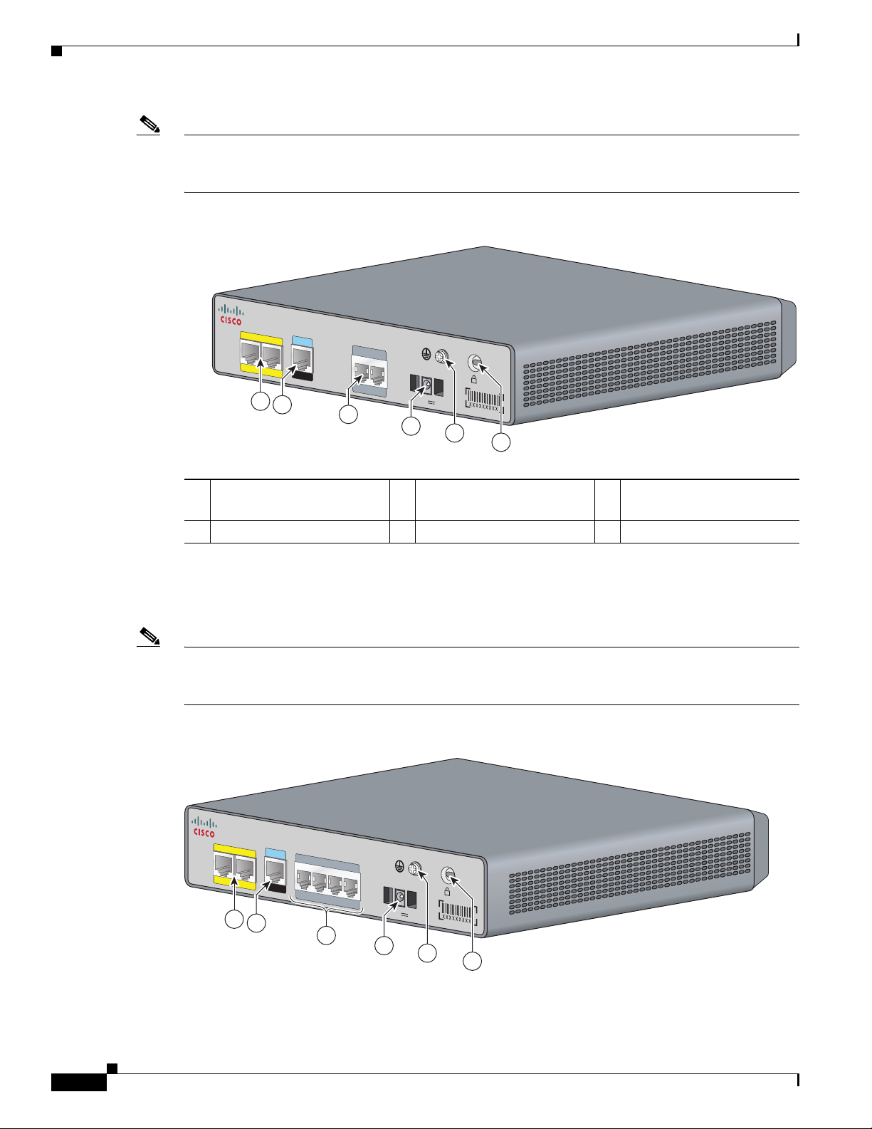
The Cisco VG202 voice gateway supports two RJ-11 ports and supports two FXS voice ports with two
10/100 Fast Ethernet ports. Figure 1-1 shows the interfaces and ports on the Cisco VG202 voice gateway.
All interface ports are on the back of the chassis.
Cisco VG202, Cisco VG202XM, Cisco VG204, and Cisco VG204XM Voice Gateways Software Configuration Guide
OL-16191-01
1-1
Page 10
Port Numbering Conventions
231880
12V DC SA
CON
SOL
E
AUX
FastEthernet
0/1
0/0
VG20 2
FXS
0/1
0/0
1
2
3
4
6
5
Note The Cisco VG202 and the Cisco VG202XM chassis are identical. The only difference is the model
number on the top center. On the Cisco VG202 chassis, the faceplate label says VG202. On the
Cisco VG202XM chassis, the faceplate label says VG202XM.
Figure 1-1 Back Panel Feature Locations on the Cisco VG202 Chassis
Chapter 1 Understanding Interface Numbering and Cisco IOS Software Basics
Fast Ethernet port 1,
1
Fast Ethernet port 0 2
Serial port—console or
auxiliary 3
FXS ports
4 Power connector 5 Chassis ground connection 6 Kensington security slot
The Cisco VG204 voice gateway supports four RJ-11ports and supports four FXS voice ports with two
10/100 Fast Ethernet ports. Figure 1-2 shows the interfaces and ports on the Cisco VG204 voice gateway.
All interface ports are on the back of the chassis.
Note The Cisco VG204 and the Cisco VG204XM chassis are identical. The only difference is the model
number on the top center. On the Cisco VG204 chassis, the faceplate label says VG204. On the
Cisco VG204XM chassis, the faceplate label says VG204XM.
Figure 1-2 Back Panel Feature Locations on the Cisco VG204 Chassis
FastEthernet
0/1
CONSOLE
0/0
AUX
1
2
VG204
FXS
0/20/3
3
0/1
0/0
12V
DC SA
4
5
6
231940
1-2
Cisco VG202, Cisco VG202XM, Cisco VG204, and Cisco VG204XM Voice Gateways Software Configuration Guide
OL-16191-01
Page 11

Chapter 1 Understanding Interface Numbering and Cisco IOS Software Basics
Understanding Cisco IOS Software Basics
Fast Ethernet port 1,
1
Fast Ethernet port 0 2
4 Power connector 5 Chassis ground connection 6 Kensington security slot
Port numbering conventions for the Cisco VG202, Cisco VG202XM, Cisco VG204, and
Cisco VG204XM voice gateways are as follows:
• Foreign Exchange Station (FXS) voice port numbering begins at 0/0 and extends to 0/1 for the
Cisco VG202 and Cisco VG202XM, and extends to 0/3for the Cisco VG204 and Cisco VG204XM.
• 10/100BASE-T Fast Ethernet ports are numbered Fast Ethernet 0/0 and Fast Ethernet 0/1, from right
to left.
Serial port—console or
auxiliary 3
Understanding Cisco IOS Software Basics
• About Cisco IOS Software, page 1-3
• Getting Help, page 1-4
• Command Modes, page 1-4
• Undoing a Command or Feature, page 1-5
• Saving Configuration Changes, page 1-5
• Upgrading to a New Cisco IOS Release, page 1-6
FXS ports
About Cisco IOS Software
Understanding these concepts about the Cisco IOS software will save time as you begin to use the CLI.
If you have never used Cisco IOS software or if you need a refresher, take a few minutes to read this
chapter before you proceed to the next chapter.
If you are already familiar with Cisco IOS software, proceed to Chapter 2, “Configuring Your Voice
Gateway Using the setup Command.”
For a comprehensive view of Cisco IOS configuration fundamentals, see the Cisco IOS Configuration
Fundamentals Configuration Guide, Release 12.4.
Note • Your Cisco IOS software release may not support all of the features documented in this document.
For the latest feature information and caveats, see the release notes for your platform and software
release.
• Use the Cisco Feature Navigator to find information about platform support and Cisco IOS and
Catalyst OS software image support. To access the Cisco Feature Navigator, go to
http://www.cisco.com/go/cfn. You do not need an account on Cisco.com to access the Cisco Feature
Navigator.
OL-16191-01
Cisco VG202, Cisco VG202XM, Cisco VG204, and Cisco VG204XM Voice Gateways Software Configuration Guide
1-3
Page 12

Understanding Cisco IOS Software Basics
• The VG202 and VG204 devices support IOS software releases 15.0(1)M or earlier* due to memory
limitations. The VG202XM and VG204XM devices will support the latest IOS software release
15.3(2)T and beyond. Earlier releases are not supported on the VG202XM and VG204XM.
*Deployments requiring support for secure SCCP based call control are supported using 15.1(4)M
IOS release.
Getting Help
Use the question mark (?) and arrow keys to help you enter commands:
• For a list of available commands, enter a question mark:
VG> ?
• To complete a command, enter a few known characters followed by a question mark (with no space):
VG> s?
• For a list of command variables, enter the command followed by a space and a question mark:
VG> show ?
Chapter 1 Understanding Interface Numbering and Cisco IOS Software Basics
• To redisplay a command you previously entered, press the up arrow key. You can continue to press
Command Modes
The Cisco IOS user interface involves different modes. Each command mode permits you to configure
different components on your voice gateway. The commands available at any given time depend on
which mode you are currently in. Entering a question mark (?) at the prompt displays a list of commands
available for each command mode. Tab le 1-1 lists the most common command modes.
Table 1-1 Common Command Modes
Command Mode Access Method VG Prompt Displayed Exit Method
User EXEC Log in.
Privileged EXEC From user EXEC mode,
the up arrow key for more commands.
enter the enable
command.
VG> Use the logout
command.
VG# To exit to user EXEC
mode, use the disable,
exit, or logout
command.
1-4
Cisco VG202, Cisco VG202XM, Cisco VG204, and Cisco VG204XM Voice Gateways Software Configuration Guide
OL-16191-01
Page 13

Chapter 1 Understanding Interface Numbering and Cisco IOS Software Basics
Understanding Cisco IOS Software Basics
Table 1-1 Common Command Modes (continued)
Command Mode Access Method VG Prompt Displayed Exit Method
Global configuration From the privileged
EXEC mode, enter the
configure terminal
command.
Interface configuration From the global
configuration mode,
enter the interface type
number command, such
as
interface fast ethernet
0/0.
Timesaver Each command mode restricts you to a subset of commands. If you are having trouble entering a
command, check the prompt, and enter the question mark (?) for a list of available commands. You might
be in the wrong command mode or using the wrong syntax.
VG(config)# To exit to privileged
EXEC mode, use the
exit or end command,
or press Ctrl-Z.
VG(config-if)# To exit to global
configuration mode, use
the exit command.
To exit directly to
privileged EXEC mode,
press Ctrl-Z.
In the following example, notice how the prompt changes after each command to indicate a new
command mode:
VG> enable
Password: <enable password>
VG# configure terminal
VG(config)# interface fastEthernet 0/0
VG(config-if)# line 0
VG(config)# exit
VG#
%SYS-5-CONFIG_I: Configured from console by console
The last message is normal and does not indicate an error. Press Return to get the VG# prompt.
Note You can press Ctrl-Z in any mode to immediately return to enable mode (VG#), instead of entering exit,
which returns you to the previous mode.
Undoing a Command or Feature
If you want to undo a command you entered or disable a feature, enter the keyword no before most
commands; for example, no ip routing.
Saving Configuration Changes
OL-16191-01
You need to enter the copy running-config startup-config command to save your configuration changes
to NVRAM, so the changes are not lost if there is a system reload or power outage. For example:
VG# copy running-config startup-config
Building configuration...
Cisco VG202, Cisco VG202XM, Cisco VG204, and Cisco VG204XM Voice Gateways Software Configuration Guide
1-5
Page 14
Chapter 1 Understanding Interface Numbering and Cisco IOS Software Basics
272489
2
1
3
4
Typical Voice Gateway Deployment Scenario
It might take a minute or two to save the configuration to NVRAM. After the configuration has been
saved, the following appears:
[OK]
VG#
Upgrading to a New Cisco IOS Release
To install or upgrade to a new Cisco IOS release, see Maintaining System Memory in the Cisco IOS
Configuration Fundamentals Configuration Guide, Release 12.2.
Note To simplify network operations and management of Cisco IOS software migration, see the Basics of a
Successful Cisco IOS Software Migration.
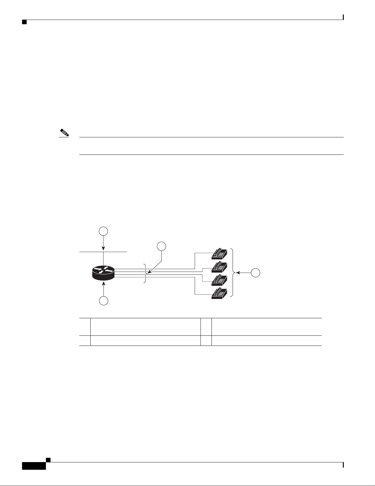
Typical Voice Gateway Deployment Scenario
Figure 1-3 shows a typical deployment scenario for a Cisco VG202, Cisco VG202XM, Cisco VG204, or
Cisco VG204XM voice gateway.
Figure 1-3 Analog FXS User Interfaces
Ethernet
1
3 RJ-11 cables 4 Analog telephones
Where to Go Next
Now that you have learned some Cisco IOS software basics and seen a typical deployment scenario, you
can begin to configure your voice gateway by using the CLI.
Cisco VG204/Cisco VG204XM voice
2
gateway
Remember that:
Cisco VG202, Cisco VG202XM, Cisco VG204, and Cisco VG204XM Voice Gateways Software Configuration Guide
1-6
• You can use the question mark (?) and arrow keys to help you enter commands.
• Each command mode restricts you to a set of commands. If you have difficulty entering a command,
check the prompt and then enter the question mark (?) for a list of available commands. You might
be in the wrong command mode or be using the wrong syntax.
OL-16191-01
Page 15

Chapter 1 Understanding Interface Numbering and Cisco IOS Software Basics
• To disable a feature, generally enter the keyword no before the command; for example, no ip
routing.
• You need to save your configuration changes to NVRAM so that the changes are not lost if there is
a system reload or power outage.
Go to Chapter 2, “Configuring Your Voice Gateway Using the setup Command,” to begin configuring
your voice gateway.
Where to Go Next
OL-16191-01
Cisco VG202, Cisco VG202XM, Cisco VG204, and Cisco VG204XM Voice Gateways Software Configuration Guide
1-7
Page 16

Where to Go Next
Chapter 1 Understanding Interface Numbering and Cisco IOS Software Basics
1-8
Cisco VG202, Cisco VG202XM, Cisco VG204, and Cisco VG204XM Voice Gateways Software Configuration Guide
OL-16191-01
Page 17

CHAP T ER
Configuring Your Voice Gateway Using the setup Command
This chapter describes how to use the setup command to configure your voice gateway. The setup
command prompts you to enter information needed to start a voice gateway functioning quickly. The
facility steps you through a basic configuration, including LAN interfaces.
• About Configuring Your Voice Gateway, page 2-1
• Preparing to Configure Your Cisco Voice Gateway, page 2-1
• Using the setup Command, page 2-2
• Completing the Configuration, page 2-5
About Configuring Your Voice Gateway
2
The Cisco VG202, Cisco VG202XM, Cisco VG204, and Cisco VG204XM voice gateways ship with a
default configuration. During the first boot up, the voice gateways do not enter setup mode and are
configured through auto-configuration.
If you prefer to configure the voice gateway manually or if you wish to configure a module or interface
that is not included in the setup command, proceed to “Chapter 3, “Configuring Your Voice Gateway
Using the CLI,” for step-by-step instructions.
If you prefer to configure the voice gateway using AutoInstall, see Using AutoInstall to Remotely
Configure Cisco Networking Devices.
Preparing to Configure Your Cisco Voice Gateway
Procedure
Step 1 Set up the hardware as described in the Cisco VG202, Cisco VG202XM, Cisco VG204, and
Cisco VG204XM Voice Gateways Hardware Installation Guide.
Step 2 Configure your PC terminal emulation program for 9600 baud, 8 data bits, no parity, and 1 stop bit.
Step 3 Determine which network protocols you support.
OL-16191-01
Cisco VG202, Cisco VG202XM, Cisco VG204, and Cisco VG204XM Voice Gateways Software Configuration Guide
2-1
Page 18

Using the setup Command
Step 4 Determine the addressing plan for each network protocol.
Using the setup Command
The setup command is displayed in your PC terminal emulation program window.
Note If you make a mistake while using the setup command, you can exit and run the command again. Press
Ctrl-C, and enter setup at the enable mode prompt (VG#).
Procedure
Step 1 Plug in the external power supply.
The system begins to display messages in your terminal emulation program window.
Chapter 2 Configuring Your Voice Gateway Using the setup Command
Caution The voice gateway does not enter setup mode during the initial configuration. During initial
configuration, the voice gateway boots up in auto-configuration. You can only use the setup command
to configure the voice gateway manually after the initial configuration. Using the setup command during
the initial configuration erases the default configuration and must be avoided.
Caution Do not press any keys on the keyboard until the messages stop. The system interprets any keys pressed
during this time as the first command typed when the messages stop, which might cause the voice
gateway to power off and start over. It takes a few minutes for the messages to stop.
The messages look similar to the following example.
System configuration has been modified. Save? [yes/no]: n
Proceed with reload? [confirm]
*Apr 21 14:23:38.051: %SYS-5-RELOAD: Reload requested by console. Reload Reason: Reload
Command.
System Bootstrap, Version 12.4(20080415:092610)
[anyname-VG.V124_19_9_2_PIA9.14582.ios.sync 102], DEVELOPMENT SOFTWARE
Copyright (c) 1994-2008 by cisco Systems, Inc.
VG202 platform with 131072 Kbytes of main memory
Upgrade ROMMON initialized
program load complete, entry point: 0x80020000, size: 0x1437d40
Self decompressing the image:
##########################################################################################
##########################################################################################
################################# [OK]
2-2
Restricted Rights Legend
Use, duplication, or disclosure by the Government is
subject to restrictions as set forth in subparagraph
(c) of the Commercial Computer Software - Restricted
Rights clause at FAR sec. 52.227-19 and subparagraph
Cisco VG202, Cisco VG202XM, Cisco VG204, and Cisco VG204XM Voice Gateways Software Configuration Guide
OL-16191-01
Page 19

Chapter 2 Configuring Your Voice Gateway Using the setup Command
(c) (1) (ii) of the Rights in Technical Data and Computer
Software clause at DFARS sec. 252.227-7013.
cisco Systems, Inc.
170 West Tasman Drive
San Jose, California 95134-1706
Cisco IOS Software, VG20X Software (VG20X-ADVIPSERVICESK9-M), Version
12.4(ORBITTY_APRIL18_POST_SYNC_BUILD.2008-04-17) UBUILDIT Image, CISCO DEVELOPMENT TEST
VERSION
Copyright (c) 1986-2008 by Cisco Systems, Inc.
Compiled Fri 18-Apr-08 02:30 by geopasaaniha
This product contains cryptographic features and is subject to United
States and local country laws governing import, export, transfer and
use. Delivery of Cisco cryptographic products does not imply
third-party authority to import, export, distribute or use encryption.
Importers, exporters, distributors and users are responsible for
compliance with U.S. and local country laws. By using this product you
agree to comply with applicable laws and regulations. If you are unable
to comply with U.S. and local laws, return this product immediately.
Using the setup Command
A summary of U.S. laws governing Cisco cryptographic products may be found at:
http://www.cisco.com/wwl/export/crypto/tool/stqrg.html
If you require further assistance please contact us by sending email to
export@cisco.com.
Cisco VG202 (MPC8300) processor (revision 0x100) with 98304K/32768K bytes of memory.
Processor board ID FOC11334C2B
MPC8300 CPU Rev: Part Number 0x8062, Revision ID 0x11
2 FastEthernet interfaces
2 Voice FXS interfaces
256K bytes of non-volatile configuration memory.
126000K bytes of ATA CompactFlash (Read/Write)
--- System Configuration Dialog ---
Would you like to enter the initial configuration dialog? [yes/no]: y
At any point you may enter a question mark '?' for help.
Use ctrl-c to abort configuration dialog at any prompt.
Default settings are in square brackets '[]'.
Step 2 When the following message appears, enter yes to begin the initial configuration dialog:
Would you like to enter the initial configuration dialog? [yes/no]:
Step 3 When the following message appears, press Return to see the current interface summary:
First, would you like to see the current interface summary? [yes]:
OL-16191-01
Any interface listed with OK? value “NO” does not have a valid configuration
Interface IP-Address OK? Method Status Protocol
FastEthernet0/0 unassigned NO unset up up
FastEthernet0/1 unassigned NO unset up down
Step 4 Enter a hostname for the voice gateway:
Configuring global parameters:
Cisco VG202, Cisco VG202XM, Cisco VG204, and Cisco VG204XM Voice Gateways Software Configuration Guide
2-3
Page 20

Using the setup Command
Enter hostname [VG]: VG204
The enable secret is a password used to protect access to privileged EXEC and
configuration modes. This password, after entered, becomes encrypted in the configuration.
Step 5 Enter an enable secret password. This password is encrypted (more secure) and cannot be seen when
viewing the configuration:
The enable secret is a password used to protect access to
privileged EXEC and configuration modes. This password, after
entered, becomes encrypted in the configuration.
Enter enable secret: cisco
Step 6 Enter an enable password that is different from the enable secret password. This password is not
encrypted (less secure) and can be seen when viewing the configuration:
The enable password is used when you do not specify an
enable secret password, with some older software versions, and
some boot images.
Enter enable password: cisco
% Please choose a password that is different from the enable secret
Enter enable password: cisco
Chapter 2 Configuring Your Voice Gateway Using the setup Command
Step 7 Enter the virtual terminal password, which prevents unauthenticated access to the voice gateway through
ports other than the console port:
The virtual terminal password is used to protect
access to the VG over a network interface.
Enter virtual terminal password: cisco
Configure SNMP Network Management? [yes]: n
Configure IP? [yes]:
Configure RIP routing? [yes]: n
Configure bridging? [no]:
Step 8 Respond to the following prompts as appropriate for your network:
Do you want to configure FastEthernet0/0 interface? [yes]:
Use the 100 Base-TX (RJ-45) connector? [yes]:
Operate in full-duplex mode? [no]:
Configure IP on this interface? [yes]:
IP address for this interface: 9.13.38.150
Subnet mask for this interface [255.0.0.0] : 255.255.255.0
Class A network is 9.0.0.0, 24 subnet bits; mask is /24
Do you want to configure FastEthernet0/1 interface? [yes]: n
Would you like to go through AutoSecure configuration? [yes]: n
AutoSecure dialog can be started later using "auto secure" CLI
The following configuration command script was created:
hostname VG-202
enable secret 5 $1$Y0VQ$D8qM6vS3qId.BP3w.GjlE.
enable password cisco
line vty 0 4
password cisco
no snmp-server
!
ip routing
no bridge 1
!
2-4
Cisco VG202, Cisco VG202XM, Cisco VG204, and Cisco VG204XM Voice Gateways Software Configuration Guide
OL-16191-01
Page 21

Chapter 2 Configuring Your Voice Gateway Using the setup Command
interface FastEthernet0/0
media-type 100BaseX
half-duplex
ip address 9.13.38.150 255.255.255.0
!
interface FastEthernet0/1
shutdown
no ip address
dialer-list 1 protocol ip permit
!
end
Completing the Configuration
After you have entered all the prompted information for the setup command, the system displays the
configuration.
Procedure
Completing the Configuration
Step 1 The system asks if you want to save this configuration, with the following options:
[0] Go to the IOS command prompt without saving this config.
[1] Return back to the setup without saving this config.
[2] Save this configuration to nvram and exit.
If you enter 0, the system does not save the configuration information that you entered, and you return
to the voice gateway enable prompt (
VG#). Enter setup to return to the system configuration dialog.
If you enter 1, the system returns you to the setup command without saving the configuration.
If you enter 2, the system saves the configuration and returns you to the user EXEC prompt
Step 2 When the messages stop appearing on your screen, press Return to get the VG> prompt.
Step 3 The VG> prompt indicates that you are now at the CLI and you have just completed a basic voice gateway
(VG>).
configuration. However, this is not a complete configuration. At this point you have two choices:
• Run the setup command again and create another configuration. Enter the following:
VG> enable
Password: password
VG# setup
• Modify the existing configuration or configure additional features with the CLI as described in
Chapter 3, “Configuring Your Voice Gateway Using the CLI.”
OL-16191-01
Cisco VG202, Cisco VG202XM, Cisco VG204, and Cisco VG204XM Voice Gateways Software Configuration Guide
2-5
Page 22

Completing the Configuration
Chapter 2 Configuring Your Voice Gateway Using the setup Command
2-6
Cisco VG202, Cisco VG202XM, Cisco VG204, and Cisco VG204XM Voice Gateways Software Configuration Guide
OL-16191-01
Page 23

CHAP T ER
3
Configuring Your Voice Gateway Using the CLI
Follow the procedures in this chapter to manually configure the voice gateway or to change the
configuration after you have run the setup command described in the “Configuring Your Voice Gateway
Using the setup Command” section on page 2-1.
• Configuring the Hostname and Password, page 3-1
• Configuring Fast Ethernet Interfaces, page 3-3
• Saving Configuration Changes, page 3-5
Note • This chapter does not describe every configuration possible—only a small portion of the most
commonly used configuration procedures. For advanced configuration topics, see the Cisco IOS
configuration guide and command reference publications.
• If you skipped Chapter 2, “Configuring Your Voice Gateway Using the setup Command,” and you
have never configured a voice gateway before, read it now. That chapter contains important
information that you need for configuring your voice gateway.
Configuring the Hostname and Password
One of the first configuration tasks is to configure the hostname and set an encrypted password.
Configuring a hostname allows you to distinguish multiple voice gateways and routers from each other.
Setting an encrypted password allows you to prevent unauthorized configuration changes.
Restriction
You can only specify a hostname if the voice gateway has a DNS server available for hostname
resolution.
SUMMARY STEPS
1. enable
2. configure terminal
3. hostname name
4. enable secret password
5. line configuration line
Cisco VG202, Cisco VG202XM, Cisco VG204, and Cisco VG204XM Voice Gateways Software Configuration Guide
OL-16191-01
3-1
Page 24

Configuring the Hostname and Password
6. exec-timeout minutes seconds
7. exit
DETAILED STEPS
Command or Action Purpose
Step 1
enable
Example:
VG# enable
Step 2
configure terminal
Example:
VG# configure terminal
Step 3
hostname name
Chapter 3 Configuring Your Voice Gateway Using the CLI
Enters privileged EXEC mode.
Enters global configuration mode. You have entered
global configuration mode when the prompt changes to
VG(config)#.
Changes the name of the voice gateway to a meaningful
name.
Step 4
Step 5
Step 6
Step 7
Example:
VG(config)# hostname VG204
enable secret password
Example:
VG(config)# enable secret guessme
line configuration line
Example:
VG(config)# line configuration 0
exec-timeout minutes seconds
Example:
VG(config-line)# exec-timeout 0 0
exit
Example:
VG(config-line)# exit
Enters an enable secret password. This password
provides access to privileged EXEC mode. When you
press enter at the user EXEC prompt (
VG>), you must
enter the enable secret password to gain access to
configuration mode. Substitute your enable secret
password for
guessme.
Enters line configuration mode to configure the console
port. When you enter line configuration mode, the
prompt changes to
VG(config-line)#.
Prevents the voice gateway’s EXEC facility from timing
out if you do not type any information on the console
screen for an extended period.
Exits to global configuration mode.
Verifying the Hostname and Password
To verify that you configured the correct hostname and password, follow these steps.
Procedure
Step 1 Enter the show config command:
VG# show config
Cisco VG202, Cisco VG202XM, Cisco VG204, and Cisco VG204XM Voice Gateways Software Configuration Guide
3-2
OL-16191-01
Page 25

Chapter 3 Configuring Your Voice Gateway Using the CLI
Using 1888 out of 126968 bytes
!
version XX.X
.
.
.
!
hostname VG204
!
enable secret 5 $1$60L4$X2JYOwoDc0.kqa1loO/w8/
.
.
.
Step 2 Check the hostname and encrypted password displayed near the top of the command output.
Step 3 Exit global configuration mode and attempt to reenter it, using the new enable password:
VG# exit
.
.
.
VG con0 is now available
Press RETURN to get started.
VG> enable
Password: guessme
VG#
Configuring Fast Ethernet Interfaces
Tip If you are having trouble, ensure the following:
• Caps lock is off.
• You entered the correct passwords. Passwords are case sensitive.
Configuring Fast Ethernet Interfaces
To configure a Fast Ethernet interface, use the configuration software provided with your voice gateway.
Otherwise, for greatest power and flexibility, use configuration mode (manual configuration).
This section describes basic Fast Ethernet interface configuration, including enabling the interface and
specifying IP routing. Depending on your own requirements and the protocols you plan to route, you
might also need to enter other configuration commands.
Before You Begin
• Connect a console to the voice gateway.
• Power on the voice gateway by plugging in the external power supply.
SUMMARY STEPS
1. enable
2. configure terminal
OL-16191-01
3. ip routing
Cisco VG202, Cisco VG202XM, Cisco VG204, and Cisco VG204XM Voice Gateways Software Configuration Guide
3-3
Page 26

Configuring Fast Ethernet Interfaces
DETAILED STEPS
Command or Action Purpose
Step 1
enable
Example:
VG# enable
Step 2
configure terminal
Example:
VG# configure terminal
Step 3
ip routing
Chapter 3 Configuring Your Voice Gateway Using the CLI
4. interface type number
5. ip address ip address subnet mask
6. exit
7. Ctrl-z
Enters privileged EXEC mode.
Enters global configuration mode.
Enables routing protocols as required for your global
configuration. This example uses IP routing.
Step 4
Step 5
Step 6
Step 7
Example
Example:
VG(config)# ip routing
interface type [number]
Example:
VG(config)# interface fastethernet 0/0
ip address ip address subnet mask
Example:
VG(config-if)# ip address 172.16.74.3
255.255.255.0
exit
Example:
VG(config-if)# exit
Ctrl-z
Example:
VG# Ctrl-z
Enters interface configuration mode. You have entered
interface configuration mode when the prompt changes
to
VG(config-if)#.
Assigns an IP address and subnet mask to the interface.
Exits to global configuration mode.
Repeat Step 4 through Step 6 if your voice gateway has
more than one interface to configure.
Returns to enable mode when you finish configuring
interfaces.
3-4
The following example shows how to configure the Fast Ethernet interface on the voice gateway:
VG-204(config)#int fa0/0
VG-204(config-if)#ip add
VG-204(config-if)#ip address 9.13.38.149 255.255.255.0
VG-204(config-if)#do sh runn int fa0/0
Building configuration...
Cisco VG202, Cisco VG202XM, Cisco VG204, and Cisco VG204XM Voice Gateways Software Configuration Guide
OL-16191-01
Page 27

Chapter 3 Configuring Your Voice Gateway Using the CLI
Current configuration : 96 bytes
!
interface FastEthernet0/0
ip address 9.13.38.149 255.255.255.0
speed auto
half-duplex
end
Saving Configuration Changes
Perform the following steps to save the voice gateway configuration.
SUMMARY STEPS
1. enable
2. copy running-config startup-config
3. Ctrl-z
Saving Configuration Changes
DETAILED STEPS
Command or Action Purpose
Step 1
enable
Example:
VG# enable
Step 2
copy running-config startup-config
Example:
VG# copy running-config startup-config
Step 3
Ctrl-z
Example:
VG# Ctrl-z
Enters privileged EXEC mode.
Saves the configuration changes to NVRAM so that they
are not lost during resets, power cycles, or power
outages.
Returns to enable mode when you finish configuring the
interfaces.
OL-16191-01
Cisco VG202, Cisco VG202XM, Cisco VG204, and Cisco VG204XM Voice Gateways Software Configuration Guide
3-5
Page 28

Saving Configuration Changes
Chapter 3 Configuring Your Voice Gateway Using the CLI
3-6
Cisco VG202, Cisco VG202XM, Cisco VG204, and Cisco VG204XM Voice Gateways Software Configuration Guide
OL-16191-01
Page 29

CHAP T ER
4
Configuring Voice
This chapter explains how to configure voice interfaces and ports, which convert telephone voice signals
for transmission over an IP network.
This chapter presents the following major topics:
• Prerequisites, page 4-1
• Configuring the Voice Interface, page 4-1
VoIP enables your Cisco VG202, Cisco VG202XM, Cisco VG204, and Cisco VG204XM voice gateways
to carry live voice traffic (for example, telephone calls and faxes) over an IP network. VoIP offers the
following benefits:
• Toll bypass
• Unified voice and data trunking
• Plain old telephone service (POTS)–Internet telephony gateways
For more information on understanding and configuring VoIP, see Configuring Voice over IP.
Prerequisites
Before you can configure your Cisco voice gateway to use VoIP, you must first do the following:
• Establish a working IP network.
• Implement a dial plan, including the following tasks:
–
Complete your company’s dial plan. That is, decide what patterns of dialed numbers will access
what telephony endpoints.
–
Establish a working telephony network based on your company’s dial plan.
–
Integrate your dial plan and telephony network into your existing IP network topology.
Configuring the Voice Interface
Whenever you install a new interface or want to change the configuration of an existing interface, you
must configure the interface.
Cisco VG202, Cisco VG202XM, Cisco VG204, and Cisco VG204XM Voice Gateways Software Configuration Guide
OL-16191-01
4-1
Page 30

Chapter 4 Configuring Voice
Configuring the Voice Interface
Note The Cisco VG202, Cisco VG202XM, Cisco VG204, and Cisco VG204XM voice gateways are fixed
voice gateways and do not support interface cards.
Before you configure an interface, have the following information available:
• Protocols you plan to route on the new interface
• IP addresses, subnet masks, network numbers, zones, or other information related to the routing
protocol
Timesaver Obtain this information from your system administrator or network plan before you begin configuring
your voice gateway.
To configure a voice interface, you must use configuration mode (manual configuration). In this mode,
you can enter Cisco IOS commands through the CLI.
Procedure
Step 1 Connect a console to the voice gateway as described in the Cisco VG202, Cisco VG202XM,
Cisco VG204, and Cisco VG204XM Voice Gateways Hardware Installation Guide.
Step 2 Power on the voice gateway. If the current configuration is no longer valid, after about one minute you
see the following prompt:
Would you like to enter the initial dialog? [yes/no]:
Answer no. You now enter the normal operating mode of the voice gateway.
Note If the current configuration is valid, you enter the normal operating mode automatically.
Step 3 After a few seconds, you see the user EXEC prompt (VG>). Type enable and the password to enter enable
mode:
VG> enable
Password: <password>
The prompt changes to the privileged EXEC (enable) prompt (VG#):
VG#
Step 4 Enter the configure terminal command to enter configuration mode:
VG# configure terminal
VG(config)#
The voice gateway enters global configuration mode, indicated by the VG(config)# prompt.
4-2
Step 5 If you have not configured the voice gateway before, or you want to change the configuration, use Cisco
IOS commands to configure global parameters, passwords, network management, and routing protocols.
In this example, IP routing is enabled:
VG(config)# ip routing
For complete information about global configuration commands, see the Cisco IOS configuration guides
and command references.
Cisco VG202, Cisco VG202XM, Cisco VG204, and Cisco VG204XM Voice Gateways Software Configuration Guide
OL-16191-01
Page 31

Chapter 4 Configuring Voice
Step 6 To configure another interface, enter the exit command to return to the VG(config)# prompt.
Step 7 To configure the voice gateway for voice traffic, see the VoIP references in the “Prerequisites” section
on page 4-1.
Step 8 To exit configuration mode and return to the enable prompt, when you finish configuring interfaces,
press Ctrl-Z. To see the current operating configuration, including any changes you just made, enter the
show running-config command:
VG# show running-config
To see the configuration currently stored in NVRAM, enter the show startup-config command at the
enable prompt:
VG# show startup-config
Step 9 The results of the show running-config and show startup-config commands differ if you have made
changes to the configuration but have not yet written them to NVRAM. To write your changes to
NVRAM and make them permanent, enter the copy running-config startup-config command at the
enable prompt:
VG# copy running-config startup-config
Building configuration. . .
[OK]
VG#
Auto-Configuration on the Cisco VG202, Cisco VG202XM, Cisco VG204, and Cisco VG204XM Voice Gateways
The Cisco voice gateway is now configured to boot in the new configuration.
Auto-Configuration on the Cisco VG202, Cisco VG202XM,
Cisco VG204, and Cisco VG204XM Voice Gateways
To configure auto-configuration on the Cisco VG202, Cisco VG202XM, Cisco VG204, and
Cisco VG204XM voice gateways, follow these guidelines and procedures.
• Restriction for Configuring Auto-Configuration
• Auto-Configuration on the Cisco VG202, Cisco VG202XM, Cisco VG204, and Cisco VG204XM
Voice Gateways
• Configuring the Voice Interface for Cisco Unified Communications Manager
• Configuring the MAC Address Convention
Restriction for Configuring Auto-Configuration
Before you can connect the voice gateway to the network, you must provision the Cisco Unified
Communications Manager (CUCM) with the voice gateway information.
Auto-Configuration With a DHCP Server
When the Dynamic Host Configuration Protocol (DHCP) server is available, the voice gateway sends a
DHCP server request to provide the IP address for the Fast Ethernet 0/0 interface, and the TFTP server’s
IP address using the DHCP option 150. When the DHCP server provides the information, the voice
Cisco VG202, Cisco VG202XM, Cisco VG204, and Cisco VG204XM Voice Gateways Software Configuration Guide
OL-16191-01
4-3
Page 32

Auto-Configuration on the Cisco VG202, Cisco VG202XM, Cisco VG204, and Cisco VG204XM Voice Gateways
gateway provisions itself with the CUCM configuration using Skinny Call Control Protocol (SCCP).
Analog ports which have been pre-configured on CUCM automatically register on CUCM as
SCCP-controlled ports.
To provision the voice gateway with auto-configuration when a DHCP server is available, use the
following commands.
SUMMARY STEPS
1. enable
2. configure terminal
3. interface type slot/port
4. ip address dhcp
5. sccp local interface-type interface-number port port-number
6. ccm-manager sccp local interface-type interface-number
7. ccm-manager sccp
8. voice service voip
Chapter 4 Configuring Voice
DETAILED STEPS
Command or Action Purpose
Step 1
enable
Example:
VG# enable
Step 2
configure terminal
Example:
VG# configure terminal
Step 3
interface type slot/port
Example:
VG(config)# interface fastethernet 0/0
Step 4
ip address dhcp
9. fax protocol t38 [nse[force]]
10. exit
Enters privileged EXEC mode.
Enters global configuration mode. You have entered
global configuration mode when the prompt changes to
VG(config)#.
Enters interface configuration mode and specifies the
type of interface you plan to configure. You have entered
interface configuration mode when the prompt changes
to
VG(config-if)#.
Acquires an IP address on an interface from the DHCP.
Step 5
4-4
Example:
VG(config-if)# ip address dhcp
sccp local interface-type interface-number port
port-type
Enables SCCP and its related applications (transcoding
and conferencing).
Example:
VG(config)# sccp local fastethernet 0/0
Cisco VG202, Cisco VG202XM, Cisco VG204, and Cisco VG204XM Voice Gateways Software Configuration Guide
OL-16191-01
Page 33

Chapter 4 Configuring Voice
Command or Action Purpose
Step 6
ccm-manager sccp local interface-type
interface-number
Example:
VG(config)# ccm-manager sccp local fastethernet
0/0
Step 7
ccm-manager sccp
Auto-Configuration on the Cisco VG202, Cisco VG202XM, Cisco VG204, and Cisco VG204XM Voice Gateways
Selects the local interface that the SCCP application uses
to register with CUCM.
Enables CUCM autoconfiguration of the Cisco IOS
gateway.
Example:
VG(config)# ccm-manager sccp
Step 8
voice service voip
Example:
VG(config)# voice service voip
Step 9
fax protocol t38 [nse[force]]
Example:
VG(config)# fax protocol t38 nse force
Step 10
exit
Example:
VG(config-line)# exit
Auto-Configuration Without a DHCP Server
When the DHCP server is not available, use the following commands to provision the voice gateway with
the CUCM configuration.
Note The ccm sccp command will remove itself if
there is no IP address configured. The command
checks every 20 seconds, up to a maximum of 8
times, then the Cisco IOS gateway will be
automatically unconfigured.
Enters voice-service configuration mode and specifies a
voice-encapsulation type.
Note This step is not necessary through
auto-configuration.
Specifies the global default ITU-T T.38 standard fax
protocol to be used for all VoIP dial peers.
Note This step is not necessary through
auto-configuration.
Exits to global configuration mode.
SUMMARY STEPS
OL-16191-01
1. enable
2. configure terminal
3. interface type slot/port
4. ip address static ip subnet mask
5. sccp local interface-type interface-number port port-number
6. voice service voip
7. fax protocol t38 [nse[force]]
8. ccm-manager sccp local interface-type interface-number
9. ccm-manager config server tftp_ip_address
10. ccm-manager sccp
Cisco VG202, Cisco VG202XM, Cisco VG204, and Cisco VG204XM Voice Gateways Software Configuration Guide
4-5
Page 34

Auto-Configuration on the Cisco VG202, Cisco VG202XM, Cisco VG204, and Cisco VG204XM Voice Gateways
11. exit
DETAILED STEPS
Command or Action Purpose
Step 1
Step 2
Step 3
Step 4
enable
Example:
VG# enable
configure terminal
Example:
VG# configure terminal
interface type slot/port
Example:
VG(config)# interface fastethernet 0/0
ip address dhcp
Enters privileged EXEC mode.
Enters global configuration mode. You have entered
global configuration mode when the prompt changes to
VG(config)#.
Enters interface configuration mode and specifies the
type of interface you plan to configure. You have entered
interface configuration mode when the prompt changes
to
VG(config-if)#.
Acquires an IP address on an interface from the DHCP.
Chapter 4 Configuring Voice
Step 5
Step 6
Step 7
Step 8
Step 9
Example:
VG(config-if)# ip address dhcp
sccp local interface-type interface-number port
port-type
Example:
VG(config)# sccp local fastethernet 0/0
voice service voip
Example:
VG(config)# voice service voip
fax protocol t38 [nse[force]]
Example:
VG(config)# fax protocol t38 nse force
ccm-manager sccp local interface-type
interface-number
Example:
VG(config)# ccm-manager sccp local fastethernet
0/0
ccm-manager config server tftp_ip_address
Example:
VG(config)# ccm-manager config server tftp
9.13.38.245
Enables the SCCP and its related applications
(transcoding and conferencing).
Enters voice-service configuration mode and specifies a
voice-encapsulation type.
Specifies the global default ITU-T T.38 standard fax
protocol to be used for all VoIP dial peers.
Selects the local interface that the SCCP application uses
to register with CUCM.
Specifies the TFTP server from which the voice gateway
downloads CUCM XML configuration files and enables
the system to download the port number of the
configuration port.
4-6
Cisco VG202, Cisco VG202XM, Cisco VG204, and Cisco VG204XM Voice Gateways Software Configuration Guide
OL-16191-01
Page 35

Chapter 4 Configuring Voice
Configuring the Voice Interface for Cisco Unified Communications Manager
Command or Action Purpose
Step 10
ccm-manager sccp
Enables CUCM auto-configuration of the Cisco IOS
gateway.
Example:
VG(config)# ccm-manager sccp
Step 11
exit
Example:
VG(config-line)# exit
Exits to global configuration mode.
Configuring the Voice Interface for Cisco Unified
Communications Manager
To configure voice ports to a CUCM server and set various parameters, including IP address, port
number, and version number, use the following commands.
Note The following steps are required only when the voice interface is configured manually and not through
SUMMARY STEPS
auto-configuration.
1. enable
2. configure terminal
3. stcapp ccm-group group-id
4. stcapp
5. stcapp feature access-code
6. stcapp feature speed-dial
7. voice-port slot-number/port
8. timeouts initial seconds
9. timeouts interdigit seconds
10. timeouts ringing seconds infinity
11. voice-port slot-number/port
12. ccm-manager fax protocol [protocol cisco]
13. ccm-manager config [server] ip-address name seconds
14. ccm-manager sccp local interface-type interface-number
15. ccm-manager sccp
16. sccp local interface-type interface-number port port-type
OL-16191-01
17. sccp
18. sccp ccm group group-number
19. associate ccm identifier-number priority priority-number
Cisco VG202, Cisco VG202XM, Cisco VG204, and Cisco VG204XM Voice Gateways Software Configuration Guide
4-7
Page 36

Configuring the Voice Interface for Cisco Unified Communications Manager
20. dial-peer voice tags pots
21. service stcapp
22. port port-number
23. exit
DETAILED STEPS
Command or Action Purpose
Step 1
enable
Example:
VG# enable
Step 2
configure terminal
Example:
VG# configure terminal
Step 3
stcapp ccm-group group-id
Chapter 4 Configuring Voice
Enters privileged EXEC mode.
Enters global configuration mode. You have entered
global configuration mode when the prompt changes to
VG(config)#.
Configures the CUCM group number for use by the
SCCP Telephony Control Application (STCAPP).
Step 4
Step 5
Step 6
Step 7
Step 8
Step 9
Example:
VG(config)# stcapp ccm-group 1
stcapp
Example:
VG(config)# stcapp
stcapp feature access-code
Example:
VG(config)# stcapp feature access-code
stcapp feature speed-dial
Example:
VG(config)# stcapp feature speed-dial
voice-port slot-number/port
Example:
VG(config)# voice-port 0/0
timeouts initial seconds
Example:
VG(config-voiceport)# timeouts initial 60
timeouts interdigit seconds
Enables STCAPP.
Enables STC application feature access codes and enters
their configuration mode.
Enables STC application feature speed-dial codes and
enters their configuration mode.
Enters voice-port configuration mode.
Configures the initial digit timeout value for a specified
voice port.
Configures the interdigit timeout value for a specified
voice port.
Example:
VG(config)# timeouts interdigit 60
Cisco VG202, Cisco VG202XM, Cisco VG204, and Cisco VG204XM Voice Gateways Software Configuration Guide
4-8
OL-16191-01
Page 37

Chapter 4 Configuring Voice
Command or Action Purpose
Step 10
timeouts ringing seconds infinity
Example:
VG(config)# timeouts ringing infinity
Step 11
voice-port slot-number/port
Example:
VG(config)# voice-port 0/1
VG(config)# voice-port 0/2
VG(config)# voice-port 0/3
Step 12
ccm-manager fax protocol [protocol cisco]
Example:
VG(config)# ccm-manager fax protocol cisco
Step 13
ccm-manager config [server] ip-address name
Example:
VG(config)# ccm-manager config server 9.13.38.245
Step 14
ccm-manager sccp local interface-type
interface-number
Configuring the Voice Interface for Cisco Unified Communications Manager
Configures the timeout value for ringing.
Enters voice-port configuration mode.
Enables fax-relay protocol for endpoints on a gateway.
Specifies the TFTP server from which the voice gateway
downloads CUCM XML configuration files and enables
the download of the configuration.
Selects the local interface that the SCCP application uses
to register with CUCM.
Step 15
Step 16
Step 17
Step 18
Step 19
Example:
VG(config)# ccm-manager sccp local fastethernet
0/0
ccm-manager sccp
Example:
VG(config)# ccm-manager sccp
sccp local interface-type interface-number port
port-type
Example:
VG(config)# sccp local fastethernet 0/0
sccp
Example:
VG(config)# sccp
sccp ccm group group-number
Example:
VG(config)# sccp ccm group 1
associate ccm identifier-number priority
priority-number
Enables CUCM auto-configuration of the Cisco IOS
gateway.
Selects the local interface that SCCP applications
(transcoding and conferencing) use to register with
CUCM.
Enables SCCP protocol and its related applications
(transcoding and conferencing).
Creates a CUCM group and enters SCCP CUCM
configuration mode.
Associates a CUCM with a CUCM group and establishes
its priority within the group.
Example:
VG(config)# associate ccm 1 priority 1
OL-16191-01
Cisco VG202, Cisco VG202XM, Cisco VG204, and Cisco VG204XM Voice Gateways Software Configuration Guide
4-9
Page 38

Configuring the MAC Address Convention
Command or Action Purpose
Step 20
Step 21
Step 22
Step 23
dial-peer voice tag pots
Example:
VG(config)# dial-peer voice 999000 pots
service stcapp
Example:
VG(config)# service stcapp
port port-number
Example:
VG(config)# port 0/0
VG(config)# port 0/1
VG(config)# port 0/2
exit
Chapter 4 Configuring Voice
Defines a particular dial peer, to specify the method of
voice encapsulation, and to enter dial-peer configuration
mode. Tag defines a particular dial peer. The tag range is
from 1 to 2147483647. The POTS peer uses VoIP
encapsulation on the IP backbone.
Enables STC application feature service.
Configures the port number.
Exits to global configuration mode.
Example:
VG(config)# exit
Configuring the MAC Address Convention
The voice gateways use the MAC address of the SCC local interface to define unique MAC addresses
for each voice port by using the last 9 digits of the SCCP local interface of the voice gateway.
For example, if the source interface MAC address is 000C.8639.5833, the MAC address of the voice port
MAC address will be C863.9583.3XXX. In the preceding example, the last 9 digits of the SCCP of the
local voice gateway become the first 9 digits of the voice port MAC address after dropping the leading
000.
The last 3 digits of the voice port MAC address is the slot number (3-bit) + subunit number (2-bit) + port
number (7-bit) in hexadecimal format. You combine the digits to get the last three MAC address digits.
For example, the voice-port 0/0 is slot number 0 (000): subunit 0 (00) and port number 0 (0000000). By
stringing the digits together, you get the following: 0000 0000 0000 = 0 0 0. This means that if the source
interface MAC address is 001f.cac3.b3f8, the MAC address of voice port 0/0 will be 1FCAC3b3f8000.
Table 4-1 shows the voice port to MAC address conversion table.
Table 4-1 Voice Port to MAC Address Conversion Chart
Last Three Digits of the MAC
Port Number
0/0 000
0/1 001
0/2 002
0/3 003
Address
4-10
Cisco VG202, Cisco VG202XM, Cisco VG204, and Cisco VG204XM Voice Gateways Software Configuration Guide
OL-16191-01
Page 39

Chapter 4 Configuring Voice
Configuring Calls
• Call Transfer, page 4-11
• Call Waiting, page 4-12
• Three-Party Conferencing, page 4-12
• Caller ID, page 4-12
Call Transfer
The voice gateways blind-call transfer functionality allows the transfer of a call from the party you call
to a destination caller without and call commit from the original person called. For example, party A
(transferee) calls party B (transferor). The transferor wants to transfer the call to party C (transfer-target)
and uses hookflash (softkey transfer) to get a dial tone, and then dials party C’s number. When
CUCM/CUCME gets party C’s number, it transfers the party A call to party C without the need of
committment from party B.
The voice gateways consultation call transfer functionality allows happens after a call is established
between a transferor and transferee. The transferor wants to transfer the call to a transfer target by using
a softkey transfer by getting a dialtone then dialing the transfer-target’s phone number. When the call
between the transferor and transfer-target is established, the transferor hangs up the phone to commit the
transfer. The CUCM/CUCME connects the call between the transferee and the transfer-target.
Configuring Calls
SUMMARY STEPS
DETAILED STEPS
Command or Action Purpose
Step 1
Step 2
enable
Example:
VG# enable
configure terminal
Example:
VG# configure terminal
1. enable
2. configure terminal
3. dial-peer voice tags pots
4. service stcapp
5. port port-number
6. exit
Enters privileged EXEC mode.
Enters global configuration mode. You have entered
global configuration mode when the prompt changes to
VG(config)#.
OL-16191-01
Cisco VG202, Cisco VG202XM, Cisco VG204, and Cisco VG204XM Voice Gateways Software Configuration Guide
4-11
Page 40

Configuring Calls
Step 3
Step 4
Step 5
Step 6
Command or Action Purpose
dial-peer voice tag pots
Example:
VG(config)# dial-peer voice 1000 pots
VG(config)# dial-peer voice 1001 pots
VG(config)# dial-peer voice 1002 pots
service stcapp
Example:
VG(config)# service stcapp
port port-number
Example:
VG(config)# port 0/0
VG(config)# port 0/1
VG(config)# port 0/2
exit
Defines a particular dial peer, to specify the method of
voice encapsulation, and to enter dial-peer configuration
mode. Tag defines a particular dial peer. The tag range is
from 1 to 2147483647. The POTS peer uses VoIP
encapsulation on the IP backbone.
Enables STC application feature service.
Configures the port number.
Exits to global configuration mode.
Chapter 4 Configuring Voice
Example:
VG(config)# exit
Call Waiting
If a calling party places a call to another party and the other party is engaged in a call, and the called
party has call waiting, the party receiving the call can suspend the current telephone call and switch to
the incoming call. For example, when caller A is engaged in a call with Caller B, a second call coming
in to caller A from caller C will cause caller A to hear the call-waiting tone (one tone with 300ms
duration), which indicates a second call. Caller A should be able to use the softkey transfer button to
answer the waiting call and then use softkey transfer to switch between the two calls.
To configure call waiting on the voice gateways, use the same commands and configuration shown in
“Call Transfer” section on page 4-11.
Three-Party Conferencing
Three-party conferencing provides a three-way conversation between three call parties. The voice
gateways along with CUCM support three-party conferencing using Cisco IOS software to perform
G.711 (ITU-T standard for audio companding) software mixing for up to three Real-time Transport
Protocol (RTP) streams
To configure three-party conferencing on the voice gateways, use the same commands and configuration
shown in the “Call Transfer” section on page 4-11.
Caller ID
4-12
Caller ID transmits a caller's number to the called party's telephone during the ringing signal.
Cisco VG202, Cisco VG202XM, Cisco VG204, and Cisco VG204XM Voice Gateways Software Configuration Guide
OL-16191-01
Page 41

Chapter 4 Configuring Voice
SUMMARY STEPS
DETAILED STEPS
Command or Action Purpose
Step 1
enable
Configuring Calls
1. enable
2. configure terminal
3. voice-port slot-number/port
4. caller-id enable [type [1|2]]
5. voice-port slot-number/port
6. caller-id enable [type [1|2]]
7. exit
Enters privileged EXEC mode.
Step 2
Step 3
Step 4
Step 5
Step 6
Step 7
Example:
VG# enable
configure terminal
Example:
VG# configure terminal
voice-port slot-number/port
Example:
VG(config)# voice-port 0/0
caller-id enable [type [1|2]]
Example:
VG(config-voice-port)# caller-id enable type 1
voice-port slot-number/port
Example:
VG(config)# voice-port 0/1
caller-id enable [type [1|2]]
Example:
VG(config-voice-port)# caller-id enable type 2
exit
Enters global configuration mode. You have entered
global configuration mode when the prompt changes to
VG(config)#.
Enters voice-port configuration mode.
Allows the sending or receiving of caller ID information.
Enters voice-port configuration mode.
Allows the sending or receiving of caller ID information.
Exits to global configuration mode.
Example:
VG(config)# exit
OL-16191-01
Cisco VG202, Cisco VG202XM, Cisco VG204, and Cisco VG204XM Voice Gateways Software Configuration Guide
4-13
Page 42

Configuring Calls
Chapter 4 Configuring Voice
4-14
Cisco VG202, Cisco VG202XM, Cisco VG204, and Cisco VG204XM Voice Gateways Software Configuration Guide
OL-16191-01
Page 43

APPENDIX
A
Using the ROM Monitor
This appendix describes the ROM monitor (also called the bootstrap program), which is the firmware
that runs when you power on or restart the Cisco VG202, Cisco VG202XM, Cisco VG204, or
Cisco VG204XM voice gateway. During normal operation, the ROM monitor helps to initialize the
processor hardware and boot the operating system software. You can also use the ROM monitor to help
you isolate or rule out hardware problems that you encounter while installing your voice gateway.
• Entering the ROM Monitor Mode, page A-1
• About the ROM Monitor Commands, page A-2
• Using the Configuration Register, page A-5
• Using the Console Download Function, page A-6
• Using Debug Commands, page A-7
• Exiting the ROM Monitor Mode, page A-8
Entering the ROM Monitor Mode
To use the ROM monitor, you must be using a terminal or PC that is connected to the voice gateway over
the console port.
Perform these steps to configure the voice gateway to boot up in ROM monitor mode the next time it is
rebooted.
SUMMARY STEPS
1. enable
2. configure terminal
3. config-register value
4. exit
5. reload
OL-16191-01
Cisco VG202, Cisco VG202XM, Cisco VG204, and Cisco VG204XM Voice Gateways Software Configuration Guide
A-1
Page 44

About the ROM Monitor Commands
DETAILED STEPS
Command or Action Purpose
Step 1
enable
Example:
VG# enable
Step 2
configure terminal
Example:
VG# configure terminal
Step 3
config-register value
Example:
VG(config)# config-register 0x2102
Step 4
exit
Appendix A Using the ROM Monitor
Enters privileged EXEC mode.
Enters global configuration mode.
Resets the configuration register settings.
Exits to global configuration mode.
Example:
VG(config)# exit
Step 5
reload
Example:
VG# reload
Timesaver Break (system interrupt) is always enabled for 60 seconds after the voice gateway reboots, regardless of
whether it is set to on or off in the configuration register. During this 60-second window, you can break
to the ROM monitor prompt by pressing the Break key.
About the ROM Monitor Commands
• Listing the ROM Monitor Commands, page A-3
• Command Descriptions, page A-3
Reboots the voice gateway with the new configuration
register value. The voice gateway remains in ROM
monitor and does not boot the Cisco IOS software.
As long as the configuration value is 0x0, you must
manually boot the operating system from the console.
See the boot command in the “Command Descriptions”
section in this appendix.
After the voice gateway reboots, it is in ROM monitor
mode. The number in the prompt increments with each
new line.
A-2
Cisco VG202, Cisco VG202XM, Cisco VG204, and Cisco VG204XM Voice Gateways Software Configuration Guide
OL-16191-01
Page 45

Appendix A Using the ROM Monitor
Listing the ROM Monitor Commands
Enter ? or help at the ROM monitor prompt to display a list of available commands and options, as
follows:
rommon 1 > ?
alias set and display aliases command
boot boot up an external process
confreg configuration register utility
cont continue executing a downloaded image
context display the context of a loaded image
cookie display contents of cookie PROM in hex
dev List the device table
dir List files in directories-dir <directory>
dis display instruction stream
frame print out a selected stack frame
help monitor builtin command help
history monitor command history
iomemset Set IO memory percent
meminfo main memory information
repeat repeat a monitor command
reset system reset
rommon-pref Select ROMMON
set display the monitor variables
showmon Display currently selected ROM monitor
stack produce a stack trace
sync write monitor environment to NVRAM
sysret print out info from last system return
tftpdnld tftp image download
unalias unset an alias
unset unset a monitor variable
xmodem x/ymodem image download
rommon 1 >
About the ROM Monitor Commands
Commands are case sensitive. You can halt any command by pressing the Break key on a terminal. If
you are using a PC, most terminal emulation programs halt a command when you press the Ctrl and the
Break keys at the same time. If you are using another type of terminal emulator or terminal emulation
software, see the documentation for that product for information on how to send a Break command.
Command Descriptions
Table A-1 describes the most commonly used ROM monitor commands.
Table A-1 Commonly Used ROM Monitor Commands
Command Description
help or ? Displays a summary of all available ROM monitor commands.
OL-16191-01
Cisco VG202, Cisco VG202XM, Cisco VG204, and Cisco VG204XM Voice Gateways Software Configuration Guide
A-3
Page 46

Recovering Boot and System Images
Table A-1 Commonly Used ROM Monitor Commands (continued)
Command Description
-? Displays information about command syntax; for example:
reset or i Resets and initializes the voice gateway, similar to a power up.
dir device: Lists the files on the named device; for example:
Appendix A Using the ROM Monitor
rommon 16 > dis -?
usage : dis [addr] [length]
The output for this command is slightly different for the xmodem download
command:
rommon 11 > xmodem -?
xmodem: illegal option -- ?
usage: xmodem [-cyrxu] <destination filename>
-c CRC-16
-y ymodem-batch protocol
rommon 5 > dir flash:
Directory of flash:
2 1343152 -rw- cVG204-advipservices-k9.mz
rommon 6 >
meminfo Lists the main memory information; for example:
rommon 6 > meminfo:
Main memory size: 128 MB.
Available main memory starts at 0x80018000
IO (packet) memory size: 5 percent of main memory
NVRAM size: 128 KB
boot commands
For more information about the ROM monitor boot commands, see the Cisco IOS
Configuration Fundamentals and Network Management Guide.
b Boots the first image in flash memory.
b flash: [filename] Attempts to boot the image directly from the first partition of flash memory. If you
do not enter a filename, this command will boot this first image in flash memory.
Recovering Boot and System Images
If your voice gateway experiences difficulties and no longer contains a valid Cisco IOS software image
in flash memory, you can recover the Cisco IOS image by using the xmodem ROM monitor command.
Use this command if the computer attached to your console has a terminal emulator that has xmodem
capability. The xmodem command establishes a connection between a console and the voice gateway
console port for disaster recovery if both the boot and system images are erased from flash memory.
A-4
The syntax for the command is xmodem [filename]. The optional parameter argument filename specifies
the source file containing the Cisco IOS image. Other options include the following:
• -c—Use cyclic redundancy check (CRC-16).
• -y—Use Ymodem transfer protocol.
Note The Cisco VG202, Cisco VG202XM, Cisco VG204, and Cisco VG204XM voice gateways only
support the -c and -y options.
Cisco VG202, Cisco VG202XM, Cisco VG204, and Cisco VG204XM Voice Gateways Software Configuration Guide
OL-16191-01
Page 47

Appendix A Using the ROM Monitor
Using the Configuration Register
• About Changing the Configuration Register, page A-5
• Changing the Configuration Register Manually, page A-5
• Changing the Configuration Register Using Prompts, page A-5
About Changing the Configuration Register
The virtual configuration register is in nonvolatile RAM (NVRAM) and has the same functionality as
other Cisco voice gateways. You can view or modify the virtual configuration register from either the
ROM monitor or the operating system software. Within the ROM monitor, you can change the
configuration register by entering the register value in hexadecimal format, or by allowing the ROM
monitor to prompt you for the setting of each bit.
Changing the Configuration Register Manually
Using the Configuration Register
To change the virtual configuration register from the ROM monitor manually, enter the confreg
command followed by the new value of the register in hexadecimal format, as shown in the following
example:
rommon 1 > confreg 0x2101
You must reset or power cycle for new config to take effect
rommon 2 >
The value is always interpreted as hexadecimal. The new virtual configuration register value is written
into NVRAM but does not take effect until you reset or reboot the voice gateway.
Changing the Configuration Register Using Prompts
Entering the confreg command without an argument displays the contents of the virtual configuration
register and a prompt to alter the contents by describing the meaning of each bit.
In either case, the new virtual configuration register value is written into NVRAM but does not take
effect until you reset or reboot the voice gateway.
The following display shows an example of entering the confreg command:
rommon 7> confreg
Configuration Summary
enabled are:
console baud: 9600
boot: the ROM Monitor
do you wish to change the configuration? y/n [n]: y
enable “diagnostic mode”? y/n [n]: y
enable “use net in IP bcast address”? y/n [n]:
enable “load rom after netboot fails”? y/n [n]:
enable “use all zero broadcast”? y/n [n]:
enable “break/abort has effect”? y/n [n]:
enable “ignore system config info”? y/n [n]:
change console baud rate? y/n [n]: y
enter rate: 0 = 9600, 1 = 4800, 2 = 1200, 3 = 2400 [0]: 0
OL-16191-01
Cisco VG202, Cisco VG202XM, Cisco VG204, and Cisco VG204XM Voice Gateways Software Configuration Guide
A-5
Page 48

Using the Console Download Function
change the boot characteristics? y/n [n]: y
enter to boot:
0 = ROM Monitor
1 = the boot helper image
2-15 = boot system
[0]: 0
Configuration Summary
enabled are:
diagnostic mode
console baud: 9600
boot: the ROM Monitor
do you wish to change the configuration? y/n [n]:
You must reset or power cycle for new config to take effect
Using the Console Download Function
• About the Console Download Function, page A-6
• Command Description, page A-6
Appendix A Using the ROM Monitor
• Error Reporting, page A-7
About the Console Download Function
You can use console download, which is a ROM monitor function, to download either a software image
or a configuration file over the voice gateway console port. After download, the file is either saved to the
mini-flash memory module or to main memory for execution (image files only).
Use the console download function when you do not have access to a TFTP server.
Note If you want to download a software image or a configuration file to the voice gateway over the console
port, you must use the ROM monitor dnld command.
Note If you are using a PC to download a Cisco IOS image over the voice gateway console port at
115,200 bps, ensure that the PC serial port is using a 16550 universal asynchronous transmitter/receiver
(UART). If the PC serial port is not using a 16550 UART, we recommend using a speed of 38,400 bps
or less when downloading a Cisco IOS image over the console port.
Command Description
A-6
The syntax for the xmodem console download command is xmodem [-c-y] destination_file_name.
• -c—Optional. Performs the download using 16-bit cyclic redundancy check (CRC-16) error
checking to validate packets. Default is 8-bit CRC.
• -y—Optional. Sets the voice gateway to perform the download using Ymodem protocol. The default
is Xmodem protocol. The protocols differ as follows:
–
Xmodem supports a 128-block transfer size. Ymodem supports a 1024-block transfer size.
Cisco VG202, Cisco VG202XM, Cisco VG204, and Cisco VG204XM Voice Gateways Software Configuration Guide
OL-16191-01
Page 49

Appendix A Using the ROM Monitor
• destination_file_name—Name of the system image file or the system configuration file. In order for
Follow these steps to run the xmodem console download command.
Procedure
Step 1 Move the image file to the local drive where Xmodem will execute.
Step 2 Enter the xmodem command.
Error Reporting
Because the ROM monitor console download uses the console to perform the data transfer, when an error
occurs during a data transfer, the system only displays the error messages on the console after the data
transfer terminates.
If you changed the baud rate from the default rate, the error message is followed by a message telling
you to restore the terminal to the baud rate specified in the configuration register.
Using Debug Commands
–
Ymodem uses CRC-16 error checking to validate each packet. Depending on the device that the
software is being downloaded from, this function might not be supported by Xmodem
the voice gateway to recognize it, the name of the configuration file must be voice gateway_confg.
Using Debug Commands
Most ROM monitor debugging commands are functional only when the Cisco IOS software has crashed
or stops. If you enter a debugging command and the Cisco IOS crash information is not available, the
system displays the following error message:
"xxx: kernel context state is invalid, can not proceed."
The following are the ROM monitor debugging commands:
• stack or k—Produces a stack trace; for example:
rommon 6> stack
Stack trace:
PC = 0x801111b0
Frame 00: FP = 0x80005ea8 PC = 0x801111b0
Frame 01: FP = 0x80005eb4 PC = 0x80113694
Frame 02: FP = 0x80005f74 PC = 0x8010eb44
Frame 03: FP = 0x80005f9c PC = 0x80008118
Frame 04: FP = 0x80005fac PC = 0x80008064
Frame 05: FP = 0x80005fc4 PC = 0xfff03d70
• context—Displays processor context; for example:
rommon 7> context
CPU context of the most recent exception:
PC = 0x801111b0 MSR = 0x00009032 CR = 0x53000035 LR = 0x80113694
CTR = 0x801065e4 XER = 0xa0006d36 DAR = 0xffffffff DSISR = 0xffffffff
DEC = 0xffffffff TBU = 0xffffffff TBL = 0xffffffff IMMR = 0xffffffff
R0 = 0x00000000 R1 = 0x80005ea8 R2 = 0xffffffff R3 = 0x00000000
R4 = 0x8fab0d76 R5 = 0x80657d00 R6 = 0x80570000 R7 = 0x80570000
R8 = 0x00000000 R9 = 0x80570000 R10 = 0x0000954c R11 = 0x00000000
R12 = 0x00000080 R13 = 0xffffffff R14 = 0xffffffff R15 = 0xffffffff
OL-16191-01
Cisco VG202, Cisco VG202XM, Cisco VG204, and Cisco VG204XM Voice Gateways Software Configuration Guide
A-7
Page 50

Exiting the ROM Monitor Mode
R16 = 0xffffffff R17 = 0xffffffff R18 = 0xffffffff R19 = 0xffffffff
R20 = 0xffffffff R21 = 0xffffffff R22 = 0xffffffff R23 = 0xffffffff
R24 = 0xffffffff R25 = 0xffffffff R26 = 0xffffffff R27 = 0xffffffff
R28 = 0xffffffff R29 = 0xffffffff R30 = 0xffffffff R31 = 0xffffffff
• frame—Displays an individual stack frame.
• sysret—Displays return information from the last booted system image. This information includes
the reason for terminating the image, a stack dump of up to eight frames, and, if an exception is
involved, the address where the exception occurred; for example:
rommon 8> sysret
System Return Info:
count: 19, reason: user break
pc:0x801111b0, error address: 0x801111b0
Stack Trace:
FP: 0x80005ea8, PC: 0x801111b0
FP: 0x80005eb4, PC: 0x80113694
FP: 0x80005f74, PC: 0x8010eb44
FP: 0x80005f9c, PC: 0x80008118
FP: 0x80005fac, PC: 0x80008064
FP: 0x80005fc4, PC: 0xfff03d70
FP: 0x80005ffc, PC: 0x00000000
FP: 0x00000000, PC: 0x00000000
Appendix A Using the ROM Monitor
• meminfo—Displays size in bytes, starting address, available range of main memory, the starting
point and size of packet memory, and size of NVRAM; for example:
rommon 9> meminfo
Main memory size: 128 MB.
Available main memory starts at 0x10000, size 40896KB
IO (packet) memory size: 5 percent of main memory.
Exiting the ROM Monitor Mode
You must set the configuration register to a value from 0x2 to 0xF for the voice gateway to boot a
Cisco IOS image from flash memory upon startup or reloading.
The following example shows how to reset the configuration register and cause the voice gateway to boot
a Cisco IOS image stored in flash memory:
rommon 1 > confreg 0x2101
You must reset or power cycle for a new configuration to take effect:
rommon 2 > boot
The voice gateway boots the Cisco IOS image in flash memory. The configuration register changes to
0x2101 the next time that you reset or power cycle the voice gateway.
A-8
Cisco VG202, Cisco VG202XM, Cisco VG204, and Cisco VG204XM Voice Gateways Software Configuration Guide
OL-16191-01
Page 51

INDEX
Symbols
-? command A-4
? command A-3
A
Analog FXS user interfaces with Metro Ethernet
interface
1-2
B
b command A-4
b flash command A-4
boot commands A-4
C
Cisco IOS 1-4, 1-5
commands
-?
A-4
b A-4
b flash A-4
boot A-4
confreg A-5
context A-7
dir device A-4
frame A-8
help A-3
i A-4
k A-7
meminfo A-8
reset A-4
ROM monitor A-3
ROM monitor debugging A-7, A-8
ROM monitor diagnostics A-1
setup 2-2
show config 3-2
stack A-7
sysret A-8
xmodem A-4, A-6
common command modes 1-4
configuration
completing
Voice over IP 4-1
configuration register
changing from ROM monitor
confreg command A-5
console download A-6 to A-7
context command A-7
controls, descriptions of 1-1, 1-2
2-5
A-5
D
debug commands, ROM monitor A-7, A-8
dir device command A-4
documentation iii-vii
E
error reporting, ROM monitor A-7
F
figures
OL-16191-01
Cisco VG202, Cisco VG202XM, Cisco VG204, and Cisco VG204XM Voice Gateways Software Configuration Guide
IN-1
Page 52

Index
Analog FXS User Interfaces with Metro Ethernet
Interface
frame command A-8
1-2
G
global configuration command mode 1-5
H
help command A-3
host name 3-1, 3-2
I
i command A-4
interface configuration command mode 1-5
entering A-1
exiting A-8
S
setup command 2-2
show config command 3-2
stack command A-7
sysret command A-8
T
tables
Common Command Modes
TFTP download
See also console download
1-4
K
k command A-7
M
meminfo command A-8
P
privileged EXEC command mode 1-4
R
recovering boot and system images A-4
related documentation iii-vii
reset command A-4
ROM monitor
commands
debug commands A-7, A-8
A-3
U
user EXEC command mode 1-4
V
virtual configuration register A-5
voice over IP
configuring
4-1
X
xmodem command A-4, A-6
IN-2
Cisco VG202, Cisco VG202XM, Cisco VG204, and Cisco VG204XM Voice Gateways Software Configuration Guide
OL-16191-01
 Loading...